

Page 1

Installation Guide
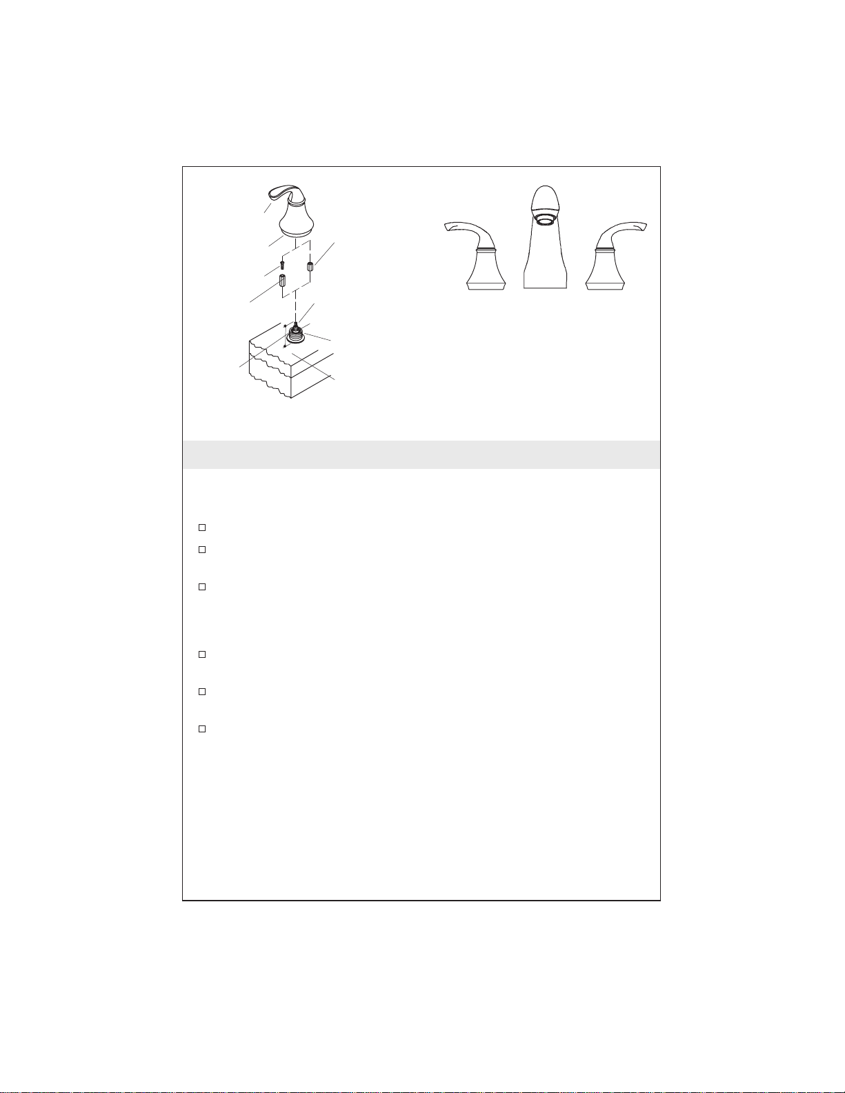
Forté
Bath/Deck Mount Faucet
K–T10278
M product numbers are for Mexico (i.e. K-12345M)
Los números de productos seguidos de
M corresponden a México (Ej.
K-12345M)
Français, page “Français-1”
Español, página “Español-1”
1017937-2-A
Page 2

Tools and Materials
Thank You For Choosing Kohler Company
We appreciate your commitment to Kohler quality. Please take a few
minutes to review this manual before you start installation. If you
encounter any installation or performance problems, please don’t
hesitate to contact us. Our phone numbers and web site are listed on
the back cover. Thanks again for choosing Kohler Company.
Before You Begin
Deep rough-in kit #73444 allows an additional 1/2” (1.3cm) of tile
thickness.
Please read all instructions before you begin.
Observe all local plumbing and building codes.
Before installation, unpack the new faucet and inspect it for damage.
Return the faucet to the carton until you are ready to install.
Leave the protective sleeve on the spout supply tube until the spout
is installed. The spout has an O-ring sealing surface which may be
damaged if unprotected.
Provide an access panel to the valves from under the deck.
Installer-supplied copper tubing is to be 5/8” O.D. (1/2” nominal).
Install water hammer arrestors in the supply lines near the valves.
These instructions cover two methods of installation; installation on
finished deck or rim, and installation on rough (unfinished) deck.
Follow the sections that pertain to your particular installation.
1017937-2-A 2 Kohler Co.
Page 3

Before You Begin (cont.)
Instructions are given for installations with 8” (20.3cm) centers. For
wider installations, adjust all roughing-in dimensions and copper
tubing lengths accordingly.
Shut off the main water supply.
Kohler Co. reserves the right to make revisions in the design of
faucets without notice, as specified in the Price Book.
Kohler Co. 3 1017937-2-A
Page 4

RIM OR DECK MOUNT
INSTALLATION
6-3/4"
(17.1cm)
7" (17.8cm)
1-1/8" D. (2.9cm)
1-13/16"
(4.6cm)
1/4"
(6mm)
TO 2-1/8"
(5.4cm)
MAX.
RIM OR
DECK
MOUNT
5/8" I.D.
(1.6cm)
ROUGH + FINISHED
DECK MOUNT INSTALLATION
8" Min. (20.3CM)
5/8" O.D. (1.6cm)
SUPPLIED BY
INSTALLER
2-13/16" D.
(7.1cm)
3/4" (1.9cm)
I.D.
1-1/4"
(3.2cm)
7/8" D.
(2.2cm)
3" (7.6cm) 2-7/8" (7.3cm)
2-3/8" D. (6cm)
TRADITIONAL
5" (12.7cm)
1/4" (6mm) TO
1-1/4" (3.2cm)
MAX. FINISHED
DECK
2-1/8" (5.4cm) MAX.
ROUGH DECK
4-11/16"
(11.9cm)
2-3/8" D. (6cm)
SCULPTED
4-5/8"
(11.7cm)
1. Prepare the Site
Install or relocate the water supplies as needed.
Protect the surfaces of the bath/deck during installation.
Ensure that holes drilled into the deck are not oversized. The spout
and valves require adequate base material strength and maximum
contact area with the deck.
Plaster guard diameters are approximately 1–5/8” (4.1cm) for the
valves and 7/8” (2.2cm) for the spout.
NOTE: Reinforcing material may be required if the deck or rim is
thin. Install before proceeding.
NOTE: For installations to be covered with tile, the tile thickness
must not exceed 1–1/4” (3.2cm).
1017937-2-A 4 Kohler Co.
Page 5

Spout Supply Tube
Supply Tube Shoulder
Threaded Sleeve
1" (2.5cm)
2-3/8" (6cm) Copper
Tube (Finished
Deck Or Bath Rim
Installation Only)
Rubber Washer
Fiber Washer
Mounting Nut
Hot Supply
Washer
Nut
Collar
Solder
Solder
1-13/16"
(4.6cm) From
Finished
Surface to Top
Plate
Wood Screws
1/2" (1.3cm)
Tee
2-7/8" (7.3cm)
Copper Tubes
of Valve Stem
Brass Washer
Valve Body
Solder
Cold
Supply
2. Installation on Finished Deck or Rim
NOTE: For installation on a rough (unfinished) deck, proceed to
Installation on Rough (Unfinished) Deck.
Use 1/2” nominal, 5/8” O.D. copper tubing. Cut two pieces of
tubing to a length of 2–7/8” (7.3cm). Cut one piece of tubing to a
length of 2–3/8” (6cm) for the spout supply.
IMPORTANT! Leave the protective sleeve on the spout supply tube
until the spout is installed to protect the O-ring sealing surface.
Install Spout Supply Tube
Slide a brass washer from the bottom of the spout supply tube over
the threads until the washer reaches the supply tube shoulder.
Insert the spout supply tube through the mounting hole from the
top of the deck/rim. Ensure that the flat portion of the washer faces
forward. The supply tube will be suspended by the washer.
From the bottom of the deck, slide the plate, with the tabs toward
the deck, and washer onto the spout supply tube. Secure with the
mounting nut.
Secure the plate to the deck with two wood screws.
Kohler Co. 5 1017937-2-A
Page 6

Installation on Finished Deck or Rim (cont.)
Install Valve Bodies
Thread one mounting nut, flange side up, followed by one fiber
washer and one rubber washer onto each valve body.
Insert the 2–7/8” (7.3cm) long copper tubes between the valve
bodies and the 1/2” tee. Insert the 2–3/8” (6cm) long copper tube
into the top of the tee.
Do not solder the connections at this time.
NOTE: The valve body marked “Cold” must be on the right side
when you are facing the front of the faucet.
Insert the valve bodies through the mounting holes from the bottom
of the deck/rim. Match the copper tube from the tee with the spout
supply tube. Hold in place.
Place a collar with the flange side up, onto each valve body. Thread
the collar down to at least 1” (2.5cm) from the top thread on the
valve body.
Install a threaded sleeve fully onto each valve body.
Thread each collar until it contacts the sleeve.
Tighten the mounting nuts on each valve body from underneath the
deck/rim.
Solder the copper tubes to the valve bodies, tee and spout supply
tube.
Ensure that the cold supply is on the right side.
Solder the hot and cold water tubes to the valve body inlets.
Proceed to Check Operation of Valves.
1017937-2-A 6 Kohler Co.
Page 7

Spout Supply Tube
Supply Tube Shoulder
Threaded Sleeve
1" (2.5cm)
Collar
Brass Washer
Plate
Wood Screws
Valve Body
Rubber Washer
Fiber Washer
Mounting Nut
Washer
Hot Supply
Nut
1/2" (1.3cm)
Tee
2-7/8" (7.3cm)
Copper Tubes
Cold
Supply
3. Installation on Rough (Unfinished) Deck
Use 1/2” nominal, 5/8” O.D. copper tubing. Cut two pieces of
tubing to a length of 2–7/8” (7.3cm).
IMPORTANT! Leave the protective sleeve on the spout supply tube
until the spout is installed to protect the O-ring sealing surface.
Install Spout Supply Tube
Slide a brass washer from the bottom of the spout supply tube over
the threads until the washer reaches the supply tube shoulder.
Insert the spout supply tube through the mounting hole from the
top of the deck. Ensure that the flat portion of the washer faces
forward. The supply tube will be suspended by the washer.
Slide the plate, with the tabs toward the deck, and washer onto the
spout supply tube from the bottom. Secure with the mounting nut.
Secure the plate to the deck with the two wood screws.
Install Valve Bodies
Thread one mounting nut, flange side up, followed by one fiber
washer and one rubber washer onto each valve body.
Insert the 2–7/8” (7.3cm) long copper tubes between the valve
bodies and the 1/2” tee.
Kohler Co. 7 1017937-2-A
Page 8

Installation on Rough (Unfinished) Deck (cont.)
Do not solder the connections at this time.
NOTE: The valve body marked “Cold” must be on the right side
when you are facing the front of the faucet.
Insert the valve bodies through the mounting holes from the bottom
of the deck.
Place a collar with the flange side up, onto each valve body. Thread
the collar down to at least 1” (2.5cm) from the top thread on the
valve body.
Install a threaded sleeve fully onto each valve body.
Thread each collar until it contacts the sleeve.
1017937-2-A 8 Kohler Co.
Page 9

Top Of Sleeve
1-1/4" (3.2cm)
Nominal
2" (5cm)
Clearance
3/4"
(2cm)
2-1/8"
(5.4cm)
Max.
Mounting
Nut
Hot
Supply
Tile
Thickness
Threaded
Collar
Copper
Tube
Solder
Solder
Spout Supply Tube
Valve
Body
Tee
Solder
Sleeve
Measure
Distance
Cold
Supply
4. Complete Installation on Rough Deck
Set Valve Body Height
NOTE: Use one of the following two formulas to calculate the valve
body clearance required for the finish material at your site.
For tile that is less than 1” (2.5cm) thick, add 1–1/4” (3.2cm) to the
tile thickness. Example: Tile thickness is 3/4” + 1–1/4” = 2” (5cm) of
clearance required.
For tile that is between 1” (2.5cm) and 1–1/4” (3.2cm) thick, add
only 1” (2.5cm) to the tile thickness. Example: Tile thickness is
1–1/4” + 1” = 2–1/4” (5.7cm).
Adjust the threaded collar until the dimension from the top of the
sleeve to the top of the rough deck equals the clearance requirement
needed. Make a note of this dimension. You will use it again after
connecting the supply tube.
Rough
Deck
Connect Supply Tube
Measure the distance from the bottom of the spout supply tube to
the top of the tee.
Add 1” (2.5cm) to this measurement and cut a piece of copper
tubing to fit into the supply tube and tee port.
Fully loosen the threaded collars but do not remove them.
Kohler Co. 9 1017937-2-A
Page 10

Complete Installation on Rough Deck (cont.)
Pivot the valve bodies enough to remove the tee and two pieces of
tubing. If the valve body holes are smaller than recommended, it
may be necessary to remove the entire valve body assembly.
Install the tubing into the tee. Match the copper tube from the tee
with the spout supply tube.
Pivot the valve bodies onto the two pieces of copper tubing.
Do not solder at this time.
Reset Valve Body Height
Adjust the threaded collars until the dimension from the top of the
sleeve to the top of the rough deck equals the clearance requirement
calculated earlier.
Solder Connections
Tighten the mounting nuts on each valve body under the deck.
Solder the copper tubes to the valve bodies, tee and spout supply
tube.
Ensure that the cold supply is on the right side.
Solder the hot and cold water supply tubes to the valve body inlets.
1017937-2-A 10 Kohler Co.
Page 11

3/8" Pipe Plug
CLOSE
HOT
CLOSE
COLD
5. Check Operation of Valves
Thread a 3/8” pipe plug into the top of the spout supply tube.
Ensure that the valves are closed (cold — fully counterclockwise; hot
— fully clockwise).
Turn on the main water supply and check the complete installation
for leaks with the valves closed and open. Repair leaks as needed.
Close both valves and turn off the main water supply.
WARNING: Risk of personal injury.
Wrap a towel around the pipe plug to prevent water spray. Water
will purge from the supply tube when you remove the plug.
Carefully loosen the pipe plug to remove pressure.
Thread the pipe plug back into the spout supply tube. Leave the
pipe plug installed until the spout and handles are installed.
Install the cardboard plaster guards over both valves and the spout
supply tube. Leave in place until the spout and handles are
installed.
Kohler Co. 11 1017937-2-A
Page 12

Sleeve
Tile
Rough
Deck
Spout Supply Tube
Threaded
Collar
1" (2.5cm) MIN.
1-1/2" (3.8cm) MAX.
1-13/16" (4.6cm) MIN.
2-5/16" (5.9cm) MAX.
6. Install Tile (If Applicable)
Verify that there will be a 1” (2.5cm) to 1–1/2” (3.8cm) distance from
the top of the sleeve to the top of the tile. If there is not, correct the
valve clearance as described earlier.
Install tile up to the plaster guards on the valves and the spout
supply tube.
NOTE: The final stem heights for both K-300 and K-301 valves are
1–13/16” (4.6cm) minimum to 2–5/16” (5.9cm) maximum from the
top of the valve to the top of the tile.
1017937-2-A 12 Kohler Co.
Page 13

7. Install Spout
Wrap a towel around the pipe plug and carefully remove it.
Remove the plaster guard from the spout supply tube.
Cut off the spout supply tube 1–1/4” (3.2cm) above the rim, finished
deck or tile.
Ensure that all burrs are removed from the supply tube.
NOTE: If your installation is on a tile-covered rough deck, slide a
brass washer, flat side facing forward, onto the supply tube. The
brass washer is supplied with the spout. This washer is not needed
for rim/finished deck installations.
Loosen the setscrews in the sleeve. Use a twisting motion to install
the sleeve on the spout supply tube until it contacts the washer.
Align the sleeve so the setscrews are not facing directly forward or
backward and tighten the setscrews.
CAUTION: Risk of product damage. Use care when installing
the spout to prevent damage to the O-ring seal on the sleeve.
Install the spout onto the sleeve and carefully press down until the
spout base contacts the finished deck surface.
Align the spout and tighten the setscrew. If included, press the plug
button into the setscrew hole.
Kohler Co. 13 1017937-2-A
Page 14
Handle
Plumbers
Putty
Screw
Brass
Spline
Adapter
Valve
Stem
Height
Measurement
Plastic
Spline
Adapter
Valve Stem
Valve Body
Threaded
Sleeve
Finished
Surface
Hot
Orientation Of Handles
In Off Position
8. Install Handles
NOTE: There are different handle styles available for this product.
Only the sculpted handle is shown. Installation of all handle styles
is identical.
Remove the plaster guards from the hot and cold valves.
Measure the distance from the top of the valve stem to the finished
surface.
For a valve stem height between 1–13/16” (4.6cm) and 2–1/8”
(5.4cm) use a brass spline adapter and screw. For a valve stem
height between 2–1/8” (5.4cm) and 2–5/16” (5.9cm) use a plastic
spline adapter.
If the brass spline adapter is required, attach using the screw
supplied. The plastic spline adapter slides on with no attachment.
Thread the handle onto the valve body. Ensure that the splines in
the handle and spline adapter are engaged.
Position the handle assemblies facing in opposite directions away
from the spout.
Cold
NOTE: The spline adapter allows fine adjustment of the handle
alignment. To adjust, unthread the handle and reposition the spline
adapter. Rethread the handle and check alignment. Repeat until
handle alignment is satisfactory.
1017937-2-A 14 Kohler Co.
Page 15

Aerator
9. Complete the Installation
Ensure that both faucet handles are turned off.
Remove the aerator assembly by turning it counterclockwise.
Turn on the main water supply and check for leaks.
Turn on the hot and cold valves and run water through the spout to
remove debris. Check for leaks.
Turn off the hot and cold valves.
Remove any debris from the aerator and reinstall.
Kohler Co. 15 1017937-2-A
Page 16

Guide d’Installation
Forté
Robinet sur baignoire ou sur plan de baignoire
Outils et matériaux
Merci d’avoir opté pour les produits de la Société Kohler
Nous apprécions votre engagement envers la qualité de Kohler.
Veuillez lire attentivement ce guide avant de commencer l’installation.
En cas de problèmes d’installation ou de fonctionnement, n’hesitez pas
à nous contacter. Nos numéros de téléphone et site web sont contenues
au plat verso. Merci encore d’avoir choisi des produits Kohler.
Avant de commencer
Le jeu d’installation profonde #73444 permet un épaisseur
additionnel de 1/2 po (1,3 cm) des carreaux.
Veuillez lire cette notice avant de commencer l’installation.
Respecter tous les codes de plomberie et de bâtiment locaux.
Avant l’installation, déballer le nouveau robinet et l’examiner
soigneusement pour déceler tout dommage. Remettre le robinet
dans l’emballage de protection en attendant de commencer
l’installation.
Laisser le manchon de protection sur le tuyau d’arrivée d’eau du
bec jusqu’à ce que le bec soit installé. Ce bec est doté d’une surface
qui assure l’étanchéité par joint torique et doit être protégée pour
éviter d’être endommagée.
Kohler Co. Français-1 1017937-2-A
Page 17

Avant de commencer (cont.)
Prévoir un panneau d’accès aux robinets, par le dessous du plan.
Le tube cuivre fourni par l’entrepreneur aura 5/8 po dia. ext. (1/2
po nominal).
Installer un antibélier dans l’arrivée d’eau, près des robinets.
Cette notice comprends deux méthodes d’installation : installation
sur plan fini ou rebord de baignoire et installation sur plan non fini.
Suivez les étapes qui s’appliquent particulièrement à votre
installation.
Ces directives de montage correspondent à un entr’axe de 8 po (20,3
cm). Si l’entr’axe dépasse 8 po (20,3 cm), modifier les dimensions
d’installation de la plomberie et les longueurs du tube cuivre en
conséquence.
Couper l’arrivée d’eau principale.
Kohler se réserve le droit d’apporter des modifications à la
conception des robinets sans avis, comme il est spécifié dans le
Catalogue des prix courants.
Kohler Co. Français-2 1017937-2-A
Page 18

1. Préparer le site
Installer ou déplacer les robinets d’arrêt au besoin.
Protéger les surfaces de la baignoire et du plan pendant
l’installation.
S’assurer de ne pas surdimentionner les trous sur le plan. Le bec et
les vannes nécessitent d’un support adéquat et d’un contact
maximale avec le plan.
Le diamètre des renforts de plâtre est d’environ 1–5/8 po (4 cm)
pour le robinet et de 7/8 po (2,2 cm) pour le bec.
REMARQUE : Prévoir un matériau de renfort si le rebord de
baignoire ou le plan de meuble est trop mince. Installer avant de
poursuivre.
REMARQUE : Pour des installations carrelées, l’épaisseur des tuiles
ne doit pas dépasser de 1–1/4 po (3,2 cm).
1017937-2-A Français-3 Kohler Co.
Page 19

2. Installation sur plan ou rebord fini
REMARQUE : Pour des installations sur un plan brut, se reporter à
la Section correspondante.
Utiliser du tube cuivre de 1/2 nominal, 5/8 po dia. ext. Couper
deux morceaux de tube de 2–7/8 (7,3 cm). Couper un morceau de
tube de 2–3/8 (6 cm), pour l’arrivée d’eau du bec.
IMPORTANT ! Laisser le manchon de protection sur le tuyau
d’arrivée d’eau du bec jusqu’à ce que le bec soit installé, pour
protéger la surface.
Installer le tube d’arrivée d’eau du bec
Glisser une rondelle en laiton sur le filetage du tube d’arrivée d’eau
du bec et contre l’épaulement du tube d’arrivée d’eau.
Insérer le tuyau d’arrivée d’eau au bec à travers l’orifice de fixation
à partir du dessus du plan ou du rebord de baignoire. S’assurer que
le plat de la rondelle soit orienté vers l’avant. Le tube d’arrivée
d’eau sera suspendu à l’aide d’une rondelle.
Poser la plaque par le dessous du plan, avec les languettes orientées
vers le plan, et la rondelle sur le tube de bec. Assujettir avec l’écrou
de fixation.
Assujettir la plaque au robinet au moyen de deux vis.
Kohler Co. Français-4 1017937-2-A
Page 20

Installation sur plan ou rebord fini (cont.)
Poser les corps de robinet
Visser un écrou d’assemblage, côté profilé vers le haut, suivi d’une
rondelle en fibre et d’une rondelle en caoutchouc, sur chaque corps
de robinet.
Loger les tubes cuivre de 2–7/8 po (7,3 cm) entre les corps de
robinet et le raccord en T de 1/2 po. Placer le tube en cuivre de
2–3/8 po (6 cm) dans l’orifice supérieur du raccord en T.
Ne pas souder à ce moment.
REMARQUE : Orienter le corps de robinet marqué “COLD” (froid)
de façon à ce qu’il soit sur la droite lorsque l’on se trouve devant le
robinet.
Introduire les corps des robinets par les trous de fixation à partir du
dessous du plan/rebord. Relier le tube en cuivre du raccord en Té
au tube d’arrivée d’eau de bec. Maintenir en place.
Poser un collier (épaulement vers le haut) sur chaque corps de
robinet. Visser sur au moins 1 po (2,5 cm) à partir du haut de
filetage du corps de robinet.
Installer un manchon fileté sur chaque corps de vanne.
Visser chaque collier jusqu’au contact du manchon.
Sous le plan/rebord de baignoire, serrer les écrous d’assemblage de
chaque corps de robinet.
Souder les tubes en cuivre aux corps de robinet, au raccord en Té et
au tube d’arrivée d’eau de bec.
S’assurer que l’arrivée d’eau froide soit sur la droite.
Souder les tuyaux d’arrivée d’eau chaude et d’eau froide aux corps
de robinet.
Vérifier le fonctionnement du robinet.
1017937-2-A Français-5 Kohler Co.
Page 21

3. Pose sur plan brut (non fini)
Utiliser du tube cuivre de 1/2 po nominal, 5/8 po dia. ext. Couper
deux morceaux de tube de 2–7/8 po (7,3 cm).
IMPORTANT ! Laisser le manchon de protection sur le tuyau
d’arrivée d’eau du bec jusqu’à ce que le bec soit installé, pour
protéger la surface.
Installer le tube d’arrivée d’eau du bec
Glisser une rondelle en laiton sur le filetage du tube d’arrivée d’eau
du bec et contre l’épaulement du tube d’arrivée d’eau.
Insérer le tuyau d’arrivée d’eau au bec à travers l’orifice de fixation
à partir du dessus du plan de meuble. S’assurer que le plat de la
rondelle soit orienté vers l’avant. Le tube d’arrivée d’eau sera
suspendu à l’aide d’une rondelle.
Poser la plaque par le dessous du plan, avec les languettes orientées
vers le plan, et la rondelle sur le tube de bec. Assujettir avec l’écrou
de fixation.
Assujettir la plaque au robinet au moyen de deux vis.
Kohler Co. Français-6 1017937-2-A
Page 22

Pose sur plan brut (non fini) (cont.)
Poser les corps de robinet
Visser un écrou d’assemblage, côté profilé vers le haut, suivi d’une
rondelle en fibre et d’une rondelle en caoutchouc, sur chaque corps
de robinet.
Loger les tubes cuivre de 2–7/8 po (7,3 cm) entre les corps de
robinet et le raccord en T de 1/2 po.
Ne pas souder à ce moment.
REMARQUE : Orienter le corps de robinet marqué “COLD” (froid)
de façon à ce qu’il soit sur la droite lorsque l’on se trouve devant le
robinet.
Introduire les corps des robinets par les trous de fixation à partir du
dessous du plan.
Poser un collier (épaulement vers le haut) sur chaque corps de
robinet. Visser sur au moins 1 po (2,5 cm) à partir du haut de
filetage du corps de robinet.
Installer un manchon fileté sur chaque corps de vanne.
Visser chaque collier jusqu’au contact du manchon.
1017937-2-A Français-7 Kohler Co.
Page 23

4. Compléter l’installation sur le plan brut
Régler la hauteur du corps de robinet
REMARQUE : Utiliser une des deux formules suivantes pour
calculer le dégagement requis au corps de robinet pour le matériau
de finition de cette installation.
Pour les tuiles de moins de 1 po (2,5 cm) d’épaisseur, ajouter 1–1/4
po (3,2 cm) à cette mesure. Example : Épaisseur de tuile :
dégagement de 3/4 po +1–1/4 po=2po(5cm)requis.
Pour les tuiles entre 1 po (2,5 cm) et 1–1/4 (3,2 cm) d’épaisseur,
ajouter seulement 1 po (3,2 cm) à cette mesure. Example : Épaisseur
de tuile : dégagement de 1–1/4 po +1 po = 2–1/4 po (5,7 cm) requis.
Régler les manchons filetés de façon à obtenir la dimension calculée
dans le cadre entre le dessus du manchon et le dessus du plan brut.
Marquer cette dimension. Ce chiffre sera de nouveau utilisé suivant
le raccordement du tube d’arrivée d’eau.
Raccorder le tuyau d’arrivée d’eau
Mesurer la distance entre la partie inférieure du tube d’arrivée d’eau
du bec et le dessus du raccord en T.
Ajouter 1 po (2,5 cm) à ce chiffre et couper un morceau de tube
cuivre pour qu’il s’ajuste au tuyau d’arrivée d’eau et à l’entrée du
Té.
Kohler Co. Français-8 1017937-2-A
Page 24

Compléter l’installation sur le plan brut (cont.)
Dévisser les manchons filetés, sans les returer complétement.
Faire basculer suffisamment les corps de robinet pour retirer le té et
les deux bouts de tuyau. Si les trous du corps de robinet sont plus
petits que prévus, il pourrait être nécessaire d’extraire complètement
le corps de robinet.
Installer le tube dans le raccord en Té. Relier le tube en cuivre du
raccord en Té au tube d’arrivée d’eau de bec.
Faire pivoter les corps de robinet sur les deux pièces de tube en
cuivre.
Ne pas souder à ce moment.
Régler la hauteur du corps de robinet
Régler les manchons filetés de façon à obtenir la dimension calculée
dans le cadre entre le dessus du manchon et le dessus du plan brut.
Souder les raccords
Sous le plan, serrer les écrous d’assemblage de chaque corps de
robinet.
Souder les tubes en cuivre aux corps de robinet, au raccord en Té et
au tube d’arrivée d’eau de bec.
S’assurer que l’arrivée d’eau froide soit sur la droite.
Souder les tuyaux d’arrivée d’eau chaude et d’eau froide aux corps
de robinet.
1017937-2-A Français-9 Kohler Co.
Page 25

5. Vérifier le fonctionnement des robinets
Visser le bouchon de tuyau de 3/8 po sur le dessus du tube
d’arrivée d’eau du bec.
S’assurer que les robinets soient fermés (côté froid — complètement
vers la gauche, côté chaud — complètement vers la droite).
Rétablir l’alimentation en eau principale et vérifier s’il y ades fuites.
Réparer au besoin.
Fermer les robinets et les robinets d’arrêt.
AVERTISSEMENT : Risque de blessures.
Enrouler une serviette autour du bouchon de tuyau pour empêcher
l’eau de gicler. L’eau s’écoulera du tube d’arrivée d’eau lorsque le
bouchon sera retiré.
Reculer soigneusement le bouchon du tuyau de manière à libérer la
pression d’eau.
Visser le bouchon de tuyau sur le tube d’arrivée d’eau de bec.
Laisser les bouchons de tuyau en place jusqu’à ce que le bec et les
poignées soient installés.
Installer les renforts de plâtre sur les deux robinets et tubes d’arrivée
d’eau de bec. Laisser en place jusqu’à ce que le bec et les poignées
soient installés.
Kohler Co. Français-10 1017937-2-A
Page 26

6. Installer les carreaux (le cas échéant)
S’assurer de prévoir une distance de 1 po (2,5 cm) à 1–1/2 po (3,8
cm) entre le dessus du manchon et le dessus du carrelage. Si le
dégagement est satisfaisant, le-corriger tel que décrit avant.
Poser les carreaux jusqu’aux renforts de plâtre sur les robinets et sur
le tube d’arrivée d’eau du bec.
REMARQUE : La hauteur finale de queue de robinet pour les
modèles K-300 et K-301 est comprise entre 1–13/16 po (4,6 cm) min.
et 2–5/16 po (5,9 cm) max. à partir du dessus du robinet, jusqu’au
dessus du carrelage.
1017937-2-A Français-11 Kohler Co.
Page 27

7. Installer le bec
Enrouler une serviette autour du bouchon de tuyau et le-retirer.
Enlever le renfort de plâtre du tube d’arrivée d’eau du bec.
Couper le tube d’arrivée d’eau de bec à environ 1–1/4 po (3,2 cm)
au-dessus du rebord, du plan de meuble fini ou du carrelage.
S’assurer d’éliminer toutes les bavures sur le tube d’arrivée d’eau.
REMARQUE : Dans les cas des installations carrellées sur plan brut,
glisser une rondelle en laiton, le côté plat dirigé vers l’avant, sur le
tube d’alimentation. La rondelle en laiton est comprise avec le bec.
La rondelle est inutile dans le cas d’une pose sur rebord/plan de
meuble fini.
Dévisser les vis de retenue sur le manchon. Par un mouvement de
torsion, enfoncer le manchon sur le tuyau d’arrivée d’eau du bec
jusqu’au contact de la rondelle.
Aligner le manchon de façon que les vis de retenue ne soient pas
orientées directement vers l’avant ou l’arrière, puis serrer les vis de
retenue.
ATTENTION : Risque d’endommagement du produit. Travailler
avec soin lors d’assembler le bec afin d’éviter d’endommager le
joint torique sur le manchon.
Installer le bec sur le manchon et appuyer graduellement jusqu’à ce
que la base du bec s’appuie contre la surface du plan de meuble fini.
Kohler Co. Français-12 1017937-2-A
Page 28

Installer le bec (cont.)
Aligner le bec et serrer doucement la vis de retenue. Le cas échéant,
poser le bouchon capsule sur le trou de vis.
1017937-2-A Français-13 Kohler Co.
Page 29

8. Installer les poignées
REMARQUE : Plusieurs styles de poignées sont proposées pour ce
produit. Seulement la poignée sculptée est illustrée. L’installation
des différents types de poignées est identique.
Enlever les renforts de plâtre des robinets d’eau chaude et froide.
Mesurer la distance entre le dessus de queue de robinet jusqu’à la
surface finie.
Utiliser l’adaptateur à cannelures et la vis lorsque la hauteur de
queue de tobinet est comprise entre 1–13/16 po (4,6 cm) et 2–1/8 po
(5,4 cm). Utiliser un adaptateur à cannelures en plastique lorsque la
hauteur de queue de robinet est comprise entre 2–1/8 po (5,4 cm) et
2–5/16 po (5,9 cm).
Lorsqu’il est nécessaire d’utiliser un adaptateur à cannelures,
raccorder avec la vis fournie. L’adaptateur à cannelures plastique ne
nécessite pas de raccord.
Visser la poignée sur le corps de robinet. S’assurer que les
cannelures de la poignée et l’adaptateur à cannelures soient bien
engagées.
Positionner les poignées de façon à ce qu’elles pointent en directions
opposées, loin de l’ensemble de bec.
REMARQUE : L’adaptateur à cannelures permet un alignement fin
de la poignée. Pour affiner l’alignement, dévisser la poignée et
repositionner l’adaptateur à cannelures. Visser à nouveau la poignée
et vérifier l’alignement. Renouveler l’opération jusqu’à ce que
l’alignement de la poignée soit satisfaisant.
Kohler Co. Français-14 1017937-2-A
Page 30

9. Compléter l’installation
S’assurer de fermer les deux poignées.
Tourner le brise-jet vers la gauche pour l’enlever.
Ouvrir les robinets d’arrivée d’eau principale et vérifier s’ilyades
fuites.
Ouvrir les poignées d’eau chaude et froide et faire couler l’eau à
travers le bec pour chasser tous les débris. Vérifier s’il y a des fuites.
Fermer les robinets d’eau.
Nettoyer le brise-jet, puis réinstaller.
1017937-2-A Français-15 Kohler Co.
Page 31

Guía de Instalación
Forté
Grifería sobre bañera o cubierta de bañera
Herramientas y materiales
Gracias por elegir los productos de Kohler
Apreciamos su elección por la calidad de Kohler. Por favor, tome unos
minutos para leer este manual, antes de comenzar la instalación. En
caso de problemas de instalación o de funcionamiento, no dude en
contactarnos. Nuestros números de teléfono y nuestra página web se
encuentran en la solapa posterior. Gracias nuevamente por escoger a
Kohler.
Antes de Comenzar
El juego para instalaciones profundas #73444 permite un grosor
adicional de 1/2″ (1,3cm) en el azulejo.
Lea estas instrucciones atentamente antes de comenzar.
Cumpla con todos los códigos locales de plomería y de construcción.
Antes de la instalación, revise con cuidado todas las piezas para ver
si están dañadas. Luego, devuelva la grifería al empaque hasta el
momento de la instalación.
Deje la manga protectora en el tubo de suministro hasta instalar el
surtidor. La superficie de sellado del empaque de anillo puede sufrir
daños si no está protegida.
Suministre acceso a las válvulas desde debajo de la cubierta.
Kohler Co. Español-1 1017937-2-A
Page 32

Antes de Comenzar (cont.)
La tubería de cobre suministrada por el instalador debe de tener un
diámetro exterior de 5/8” (1/2” nominal).
Instale el amortiguador de choques de agua en las líneas de
suministro cerca de las válvulas.
Estas instrucciones incluyen dos metódos de instalación: sobre borde
o cubierta acabada y sobre cubierta sin acabar. Siga las secciones
correspondientes a su instalación particular.
Las instrucciones para la instalación con centros de 8” (20,3cm) están
incluidas. Para instalaciones mayores, ajuste todas las dimensiones
brutas y la longitud de la tubería de cobre como corresponde.
Cierre el suministro principal de agua.
Kohler Co. se reserva el derecho de modificar el diseño de la grifería
sin previo aviso, tal como se especifica en la lista de precios.
1017937-2-A Español-2 Kohler Co.
Page 33

1/4" (6mm) A
1-1/4" (3,2cm)
MÁX. CUBIERTA
ACABADA
1. Preparación del sitio
Cuando sea necesario instale o traslade los suministros.
Proteja las superficies de la bañera y de la cubierta durante la
instalación.
Verifique que los orificios perforados en la cubierta no sean
demasiado grandes. El surtidor y las válvulas requieren de apoyo
sólido y de yun área de contacto máximo con la cubierta.
El diámetro del protector de yeso es de aproximadamente 1–5/8”
(4cm) para la válvula y 7/8” (2,2cm) para el surtidor.
NOTA: Es posible que se necesite un material de refuerzo si la
cubierta o el borde es de bajo grosor. Instale antes de proseguir.
NOTA: Para instalaciones a ser cubiertas con azulejos, el grosor del
azulejo no debe exceder 1–1/4” (3,2cm).
Kohler Co. Español-3 1017937-2-A
Page 34

2. Instalación sobre borde o cubierta acabada
NOTA: Para instalaciones sobre cubierta sin acabar, prosiga a la
sección con el mismo título.
Utilice tubería nominal de cobre de 1/2”, 5/8” diám. ext. Corte
piezas de tubería de 2–7/8” (7,3cm) de longitud. Corte piezas de
tubería de 2–3/8” (6cm) de longitud para el suministro del surtidor.
¡IMPORTANTE! Deje la manga protectora en el tubo de suministro
del surtidor hasta haber instalado el surtidor, a fin de proteger la
superficie de sellado del empaque de anillo.
Instale el tubo de suministro del surtidor
Deslice una arandela de bronce desde la parte inferior del tubo de
suministro del surtidor sobre las roscas hasta que la arandela esté en
contacto con el reborde del tubo de suministro.
Inserte el tubo de suministro del surtidor por el orificio de montaje,
desde la parte superior de la cubierta/borde. Verifique que la parte
plana de la arandela esté orientada hacia el frente. El tubo de
suministro estará suspendido por la arandela.
A partir de la parte inferior de la cubierta, deslice la placa con las
lengüetas orientadas hacia la cubierta, y la arandela sobre el tubo de
suministro del surtidor. Asegure con la tuerca de montaje.
Fije la placa a la cubierta con dos tornillos para madera.
1017937-2-A Español-4 Kohler Co.
Page 35

Instalación sobre borde o cubierta acabada (cont.)
Instale los cuerpos de la válvula
Enrosque una tuerca de fijación, con la brida hacia arriba, una
arandela de fibra y una de goma a cada cuerpo de válvula.
Inserte tubos de cobre de 2–7/8” (7,3cm) entre los cuerpos de la
válvula y la T de 1/2”. Luego, inserte el tubo de cobre de 2–3/8”
(6cm) en la parte superior de la T.
No solde las conexiones en este momento.
NOTA: Verifique que la válvula marcada “COLD” esté a la derecha
cuando se vea desde el frente de la grifería.
Inserte los cuerpos de la válvula a través de los orificios de fijación
desde la parte inferior de la cubierta o del borde. Conecte el tubo de
cobre de la T al tubo de suministro del surtidor. Sostenga en su
lugar.
Coloque un collarín en cada cuerpo de la válvula, con la brida
orientada hacia arriba. Enrosque el collarín al menos 1” (2,5cm) de
la rosca superior al cuerpo de la válvula.
Instale una manga roscada en cada cuerpo de la válvula.
Enrosque un collarín hasta que toque la manga.
Enrosque las tuercas de montaje a cada cuerpo de la válvula desde
la parte inferior de la cubierta o el borde.
Solde los tubos de cobre a los cuerpos de la válvula, a laTyaltubo
de suministro del surtidor.
Verifique que el suministro del agua fría esté a la derecha.
Solde los suministros de agua fría y caliente a las entradas del
cuerpo de la válvula.
Proceda a verificar el funcionamiento de las válvulas.
Kohler Co. Español-5 1017937-2-A
Page 36

3. Para instalaciones sobre cubiertas sin acabar
Utilice tubería nominal de cobre de 1/2”, 5/8” diám. ext. Corte
piezas de tubería de 2–7/8” (7,3cm) de longitud.
¡IMPORTANTE! Deje la manga protectora en el tubo de suministro
del surtidor hasta haber instalado el surtidor, a fin de proteger la
superficie de sellado del empaque de anillo.
Instale el tubo de suministro del surtidor
Deslice una arandela de bronce desde la parte inferior del tubo de
suministro del surtidor sobre las roscas hasta que la arandela esté en
contacto con el reborde del tubo de suministro.
Inserte el tubo de suministro del surtidor a través del orificio de
montaje desde la parte superior de la cubierta. Verifique que la parte
plana de la arandela esté orientada hacia el frente. El tubo de
suministro estará suspendido por la arandela.
A partir de la parte inferior de la cubierta, deslice la placa con las
lengüetas orientadas hacia la cubierta, y la arandela sobre el tubo de
suministro del surtidor. Asegure con la tuerca de montaje.
Fije la placa a la cubierta con dos tornillos para madera.
1017937-2-A Español-6 Kohler Co.
Page 37

Para instalaciones sobre cubiertas sin acabar (cont.)
Instale los cuerpos de la válvula
Enrosque una tuerca de fijación, con la brida hacia arriba, una
arandela de fibra y una de goma a cada cuerpo de válvula.
Inserte tubos de cobre de 2–7/8” (7,3cm) entre los cuerpos de la
válvula y la T de 1/2”.
No solde las conexiones en este momento.
NOTA: Verifique que la válvula marcada “COLD” esté a la derecha
cuando se vea desde el frente de la grifería.
Inserte los cuerpos de la válvula a través de los orificios de fijación,
desde la parte inferior de la cubierta.
Coloque un collarín en cada cuerpo de la válvula, con la brida
orientada hacia arriba. Enrosque el collarín al menos 1” (2,5cm) de
la rosca superior al cuerpo de la válvula.
Instale una manga roscada en cada cuerpo de la válvula.
Enrosque un collarín hasta que toque la manga.
Kohler Co. Español-7 1017937-2-A
Page 38

4. Complete la instalación sobre la cubierta
Determine la altura del cuerpo de la válvula
NOTA: Utilice una de las siguientes fórmulas para calcular el
espacio libre del cuerpo de la válvula requerido para el material
acabado.
Para azulejos de menos de 1” (2,5cm) de grosor, sume 1–1/4”
(3,2cm) a el grosor del azulejo. Ejemplo: Grosor del azulejo: 3/4” +
1–1/4” = 2” (5cm) de espacio libre requerido.
Para azulejos entre 1” (2,5cm) y 1–1/4” (3,2cm) de grosor, sume 1”
(2,5cm) a el grosor del azulejo. Ejemplo: Grosor del azulejo: 1–1/4”
+1” =2–1/4” (5,7cm).
Ajuste el collarín roscado hasta que la dimensión desde la parte
superior de la manga hasta la parte superior de la cubierta bruta
iguale el espacio libre requierido. Tome nota de esta dimensión. La
misma será necesaria después de conectar el tubo de suministro.
Conecte el tubo de suministro
Mida la distancia entre el fondo del tubo de suministro y la parte
superior de la T.
Añada 1” (2,5cm) a esta medida y corte una pieza de tubería de
cobre que se ajuste al tubo de suministroyalasalida de la T.
Afloje los collarines roscados sin removerlos.
1017937-2-A Español-8 Kohler Co.
Page 39

Complete la instalación sobre la cubierta (cont.)
Rote los cuerpos de la válvula lo suficiente para remover laTylas
dos piezas de tubería. Si los orificios del cuerpo de la válvula son
más pequeños de lo recomendado, es posible que se deba remover
todo el montaje del cuerpo de la válvula.
Instale la tubería en la T. Conecte el tubo de cobre de la T al tubo de
suministro del surtidor.
Rote el cuerpo de las válvulas sobre las dos piezas de tubería de
cobre.
No solde en este momento.
Establezca nuevamente la altura del cuerpos de la
válvula
Ajuste el collarín roscado hasta que la dimensión desde la parte
superior de la manga hasta la parte superior de la cubierta bruta
iguale el espacio libre calculado anteriormente.
Solde las conexiones
Enrosque las tuercas de montaje en cada cuerpo de la válvula desde
la parte inferior de la cubierta.
Solde los tubos de cobre a los cuerpos de la válvula, a laTyaltubo
de suministro del surtidor.
Verifique que el suministro del agua fría esté a la derecha.
Solde los tubos de suministro de agua fría y caliente a las entradas
del cuerpo de la válvula.
Kohler Co. Español-9 1017937-2-A
Page 40

5. Verifique el funcionamiento de las válvulas
Enrosque un obturador de 3/8″ en la parte superior del tubo de
suministro del surtidor.
Verifique que las válvulas estén cerradas (caliente — sentido horario;
fría — sentido antihorario).
Abra el suministro del agua y verifique que no haya fugas en la
instalación cuando las válvulas estén abiertas y cerradas. Repare de
ser necesario.
Cierre ambas válvulas y el suministro principal de agua.
ADVERTENCIA: Riesgo de lesiones personales.
Envuelva el obturador con una toalla para impedir que el agua salga
a presión. El agua se purgará del tubo de suministro al remover el
obturador.
Con cuidado, levante levemente el obturador de la tubería para
aliviar la presión.
Enrosque el obturador nuevamente al tubo de suministro. Deje el
obturador en el tubo de suministro hasta instalar el surtidor y la
manija.
Instale los protectores de yeso sobre ambas válvulas y el tubo de
suministro del surtidor. Deje los protectores de yeso en su lugar
hasta instalar el surtidor y las manijas.
1017937-2-A Español-10 Kohler Co.
Page 41

6. Instale el azulejo (de ser el caso)
Verifique que haya una distancia de 1″ (2,5cm) a 1–1/2″ (3,8cm)
entre la parte superior de la manga y el azulejo. De no ser así,
corrija la distancia tal como se describe anteriormente.
Instale el azulejo hasta los protectores de yeso de las válvulas y el
tubo de suministro del surtidor.
NOTA: La altura final del vástago para las válvulas K-300 y K-301
oscila entre 1–13/16″ (4,6cm) mínimo y 2–5/16″ (5,9cm) máximo,
desde la parte superior de la válvula hasta la parte superior del
azulejo.
Kohler Co. Español-11 1017937-2-A
Page 42

7. Instale el surtidor
ENvuelva una toalla alrededor del obturador y remuévalo con
cuidado.
Remueva el protector de yeso de la tubería de suministro del
surtidor.
Corte la tubería de suministro del surtidor 1–1/4” (3,2cm) por
encima del borde, cubierta acabada o azulejo.
Asegúrese de remover las rebabas del tubo de suministro.
NOTA: Para instalaciones sobre cubiertas sin acabar con azulejos,
deslice una arandela de bronce sobre el tubo de suministro, con el
lado plano orientado hacia adelante. La arandela de bronce viene
incluida con el surtidor. La arandela no es necesaria en instalaciones
sobre bordes o cubiertas acabadas.
Afloje los tornillos de fijación de la manga. Instale la manga en el
tubo de suministro del surtidor hasta su contacto con la arandela.
Alinee la manga para que los tornillos de fijación no estén
orientados directamente hacia el frente ni hacia atrás, y asegure los
tornillos.
PRECAUCIÓN: Riesgo de daños al producto. Tenga cuidado al
instalar el montaje del surtidor, a fin de no causar daños al sello
del empaque de anillo en la manga.
1017937-2-A Español-12 Kohler Co.
Page 43

Instale el surtidor (cont.)
Instale el surtidor en la manga y presione hacia abajo hasta que la
base del surtidor esté en contacto con la superficie de la cubierta
acabada.
Alinee el surtidor y asegure el tornillo de fijación. Si está incluido,
presione el botón del obturador en el orificio del tornillo de fijación.
Kohler Co. Español-13 1017937-2-A
Page 44

8. Instale las manijas
NOTA: Hay diversos estilos de manijas disponibles para este
producto. Se ha ilustrado la manija esculpida solamente. La
instalación de los diversos estilos de manias es idéntica.
Remueva los protectores de yeso de las válvulas de agua fría y
caliente.
Mida la distancia entre la parte superior del vástago de la válvula
hasta la superficie acabada.
Utilice un adaptador de ranura y un tornillo, en caso de que la
altura del vástago de la válvula sea entre 1–13/16” (4,6cm) y 2–1/8”
(5,4cm). Utilice el adaptador de ranura de plástico en caso de que la
altura del vástago de la válvula esté entre 2–1/8″ (5,4cm) y 2–5/16″
(5,9cm).
Si se requiere de un adaptador de ranura de bronce, conecte con el
tornillo incluido. El adaptador de ranura de plástico se ajusta sin
necesidad de tornillos.
Enrosque la manija al cuerpo de la válvula. Verifique que las
ranuras en la manija y el adaptador de ranura estén engranados.
Coloque los montajes de la manija orientados en dirección contraria
respecto al montaje del surtidor.
NOTA: El adaptador de ranura permitirá el buen ajuste de la
manija. Para ajustar, desenrosque la manija y coloque nuevamente el
adaptador de ranura. Enrosque la manija nuevamente y verifique la
alineación. Repita hasta obtener una alineación satisfactoria.
1017937-2-A Español-14 Kohler Co.
Page 45

9. Complete la instalación
Verifique que las manijas de la grifería estén cerradas.
Gire el aireador hacia la izquierda para removerlo.
Abra el suministro de agua y verifique que no haya fugas.
Abra las válvulas del agua y permita que el agua corra para limpiar
el sistema. Verifique que no haya fugas.
Cierre las válvulas.
Limpie el aireador y reinstale.
Kohler Co. Español-15 1017937-2-A
Page 46

1017937-2-A
Page 47

1017937-2-A
Page 48

USA: 1-800-4-KOHLER
Canada: 1-800-964-5590
México: 001-877-680-1310
kohler.com
©2003 Kohler Co.
1017937-2-A
 Loading...