

Page 1
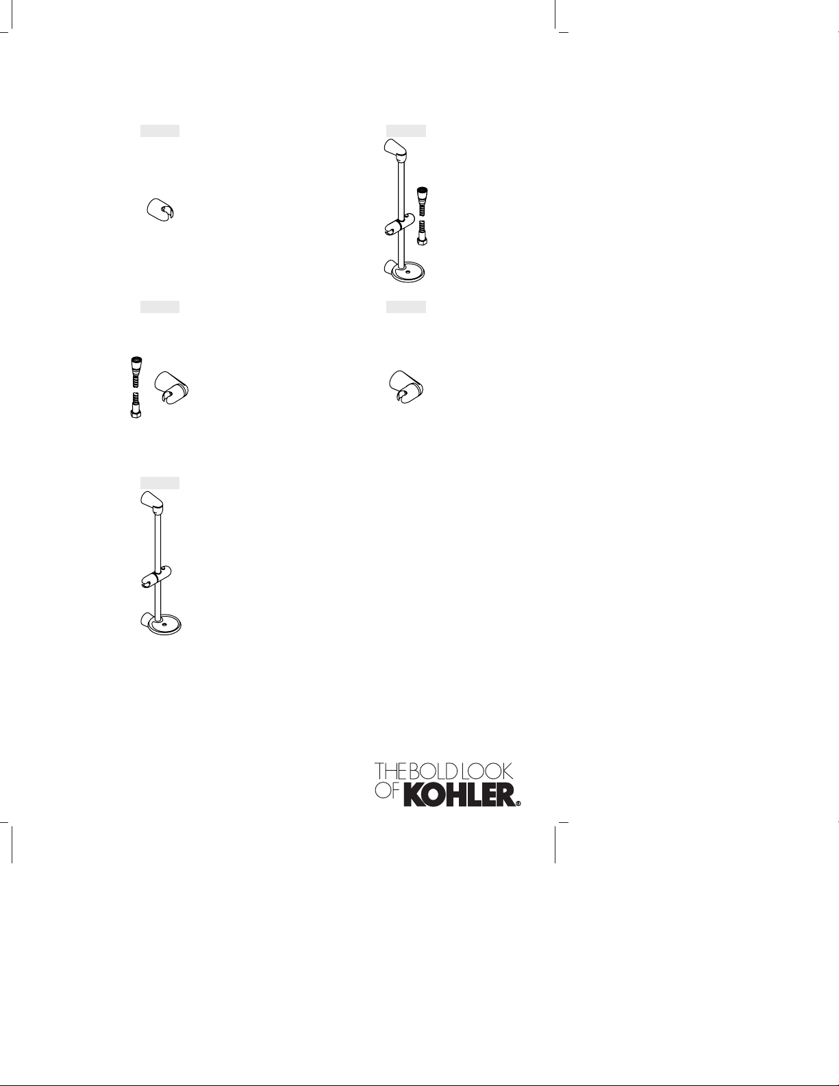
Installation Guide
Shower Accessories
K-8515 K-8516
K-8517 K-9515
K-9516
M product numbers are for Mexico (i.e. K-12345M)
Los números de productos seguidos de
M corresponden a México (Ej.
K-12345M)
Français, page“ Français-1”
Español, página“ Español-1”
089408-2-AC
Page 2
Thank You For Choosing Kohler Company
We appreciate your commitment to Kohler quality. Please take a few
minutes to review this manual before you start installation. If you
encounter any installation or performance problems please don’t
hesitate to contact us. Our phone numbers and website are listed on
the back cover. Thanks again for choosing Kohler Company.
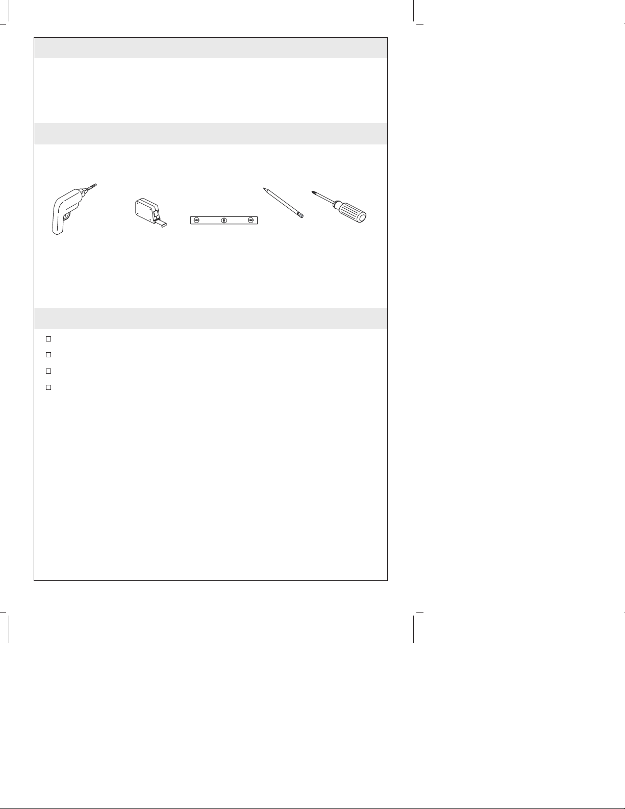
Tools and Materials
Drill and
Assorted Bits
Tape
Measure
Level Pencil Phillips
Screwdriver
Before You Begin
Observe all local plumbing and building codes.
Shut off the main water supply.
Replace waste or supply tubing if necessary.
Kohler Co. reserves the right to make revisions in the design of
products without notice, as specified in the Price Book.
089408-2-AC 2 Kohler Co.
Page 3
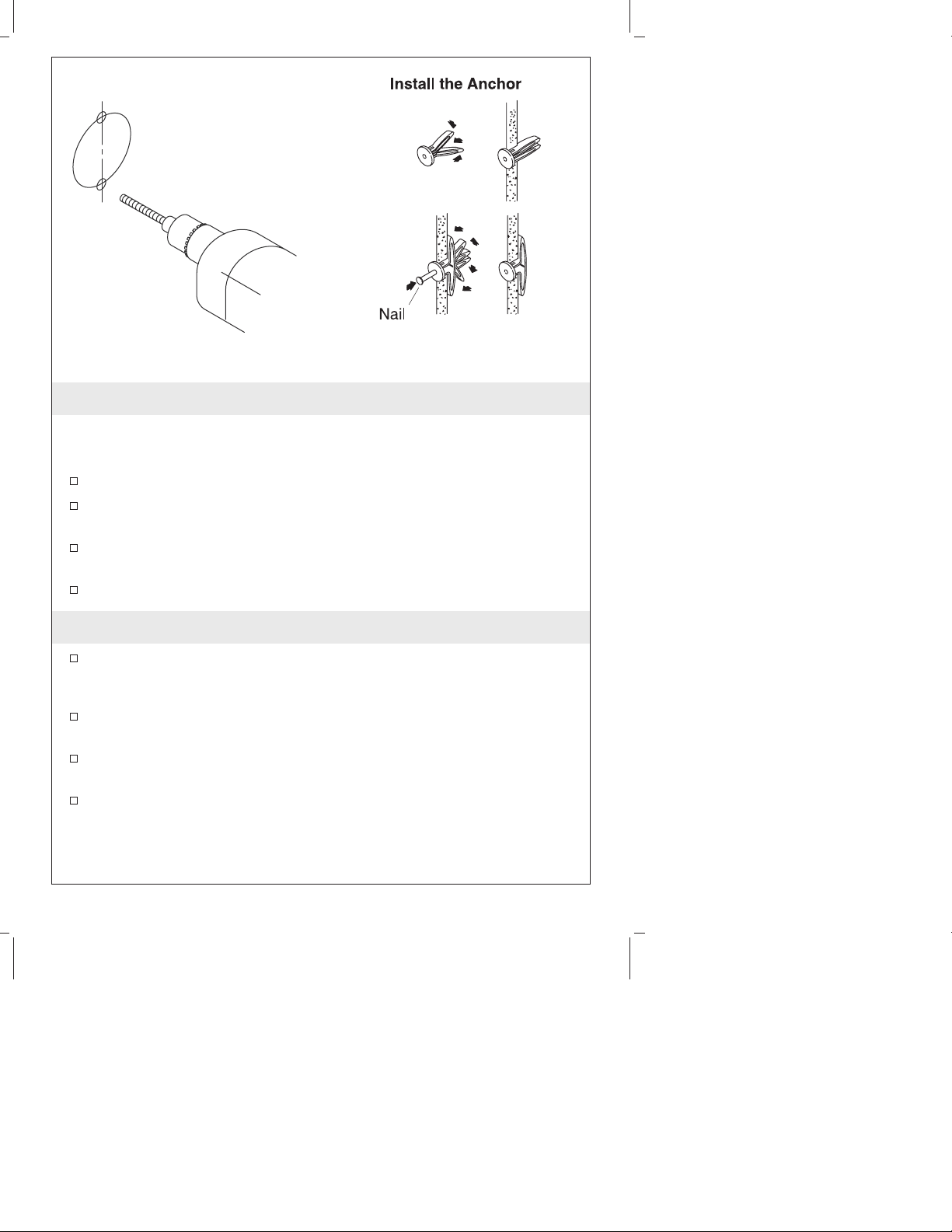
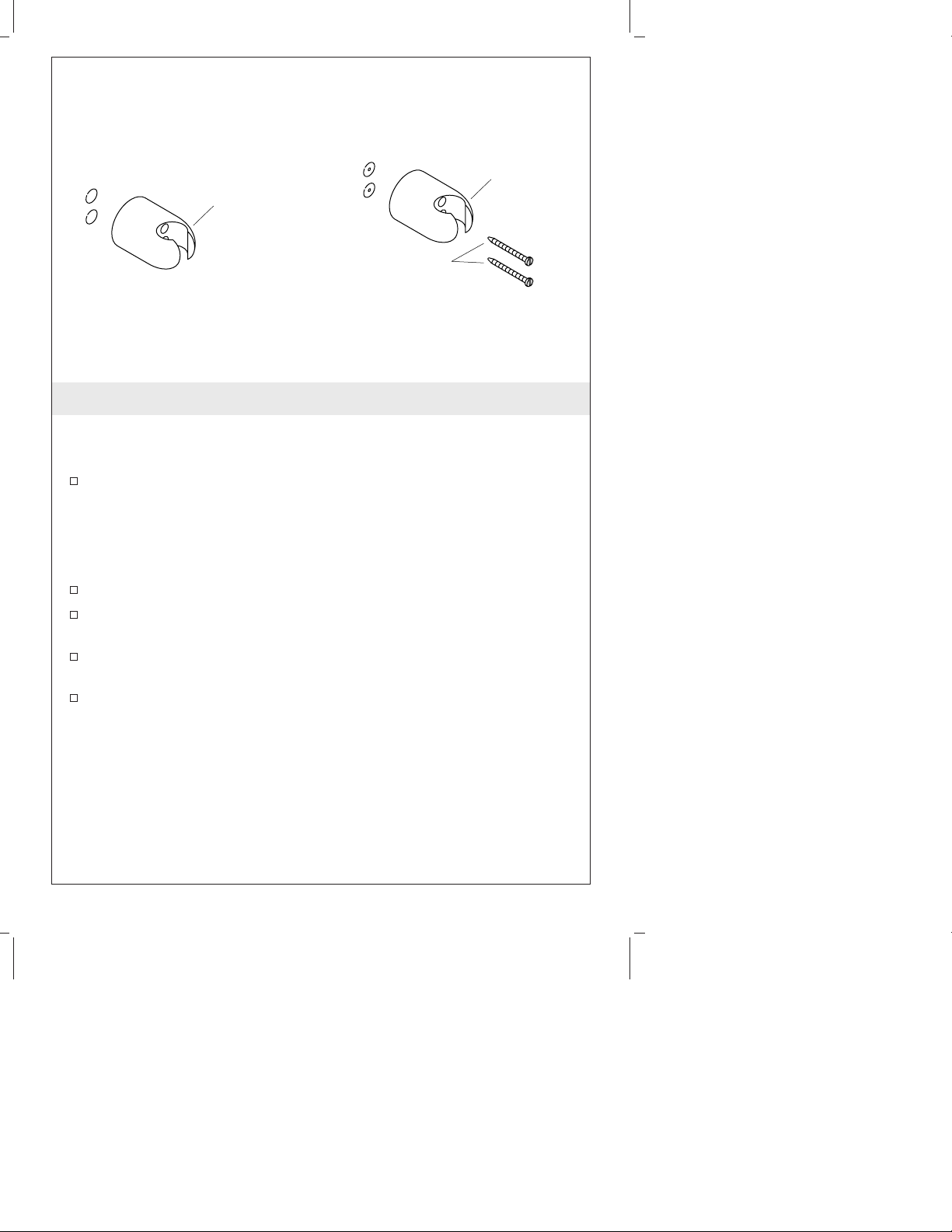
1. Prepare the Handshower Bracket
NOTE: This accessory should not be installed in the area 24″ (61 cm)
to 48″ (121.9 cm) from the floor (the critical support area as defined
in ASTM F446).
Press the tab, and separate the housing from the bracket.
Position the bracket on the finished wall, and mark the top and
bottom hole locations.
Drill a 3/16″ hole through the tile only to mount directly to a
stud.
If a stud cannot be located, drill a 3/8″ hole.
2. Install the Anchors
Press and hold the legs of a wall anchor (provided) together and
insert the wall anchor legs into the hole. Insert a wall anchor into
each pre-drilled mounting hole.
With a hammer, carefully tap each wall anchor until they are
flush with the finished surface.
If the wall anchor was inserted into a space between the studs, it
will be necessary to spread the wall anchor legs.
To spread the anchor legs, insert a thin long object, such as a
finishing nail, into the wall anchor hole.
Kohler Co. 3 089408-2-AC
Page 4
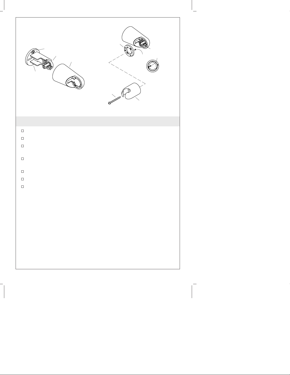
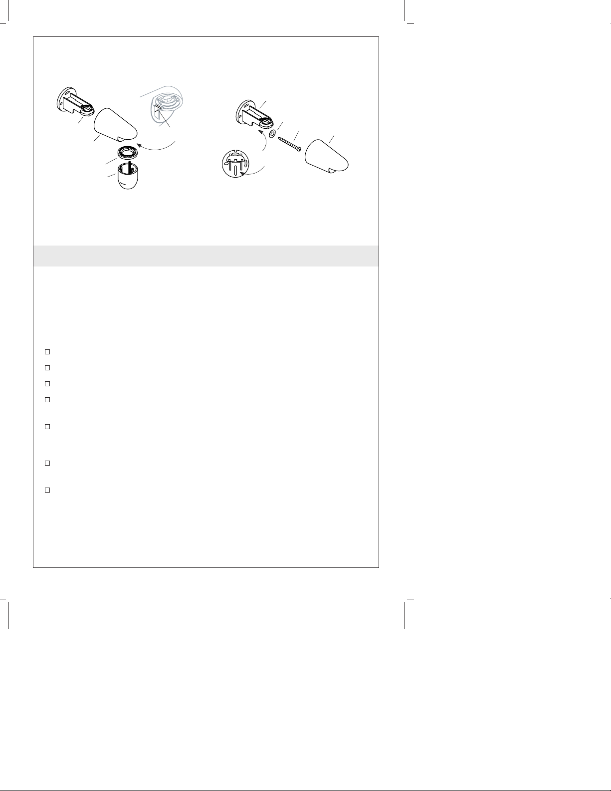
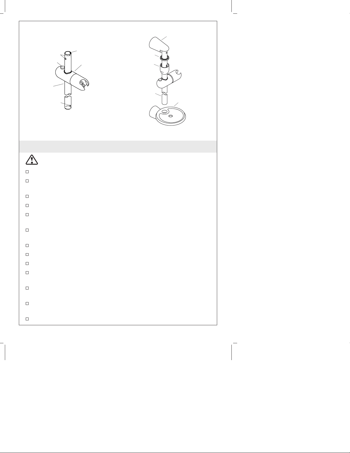
Screw
Bracket
Housing
Ring
Housing
Tab
Larger Indent
Screw
Screw
Back View
Spray Holder
3. Install the Spray Holder
Secure the bracket to the finished wall with the provided screws.
Fit the housing over the bracket, and snap it into place.
Position the ring onto the housing with the larger of the two
indents situated over the housing tab.
Position the spray holder on the ring with the tapered end of the
groove facing down.
Secure the spray holder in place with the provided screw.
Tighten until snug. The spray holder should be able to rotate.
Adjust the screw as needed.
089408-2-AC 4 Kohler Co.
Page 5
Wall
Wall
Bracket
Screws
Bracket
4. Install the Wall Bracket
NOTE: This accessory should not be installed in the area 24″ (61 cm)
to 48″ (121.9 cm) from the floor (the critical support area as defined
in ASTM F446).
Position the wall bracket in the desired install location against the
finished wall, and mark the top and bottom hole locations.
NOTE: Drill the holes with a 3/16″ bit, penetrating through the tile
only when mounting directly to a stud. If the bracket is not being
mounted directly to a stud, drill the holes using a 3/8″ drill bit.
Drill a hole at each mark.
If required, insert wall anchors into the holes following the
directions in the ″Install the Anchors″ section.
Position the wall bracket against the finished wall with the
tapered end of the groove down.
Secure the bracket with the provided screws.
Kohler Co. 5 089408-2-AC
Page 6
Bracket
Bracket
Top Housing
Ring
Top Cover
Tab
Washer
Screw
Slotted Hole
Front View
T op
Housing
5. Install the Top Bracket
IMPORTANT! The slide bar must be mounted to stud framing
supports at both the top and bottom. Wall anchors will not support
the slide bar.
NOTE: This accessory should not be installed in the area 24″ (61 cm)
to 48″ (121.9 cm) from the floor (the critical support area as defined
in ASTM F446).
Separate the top cover and housing by pulling firmly.
Remove the ring.
Press the tab, and separate the housing from the bracket.
Position the bracket on the finished wall, and mark the top
location of the centermost slotted hole.
Drill a hole at the marked location.
NOTE: Do not use wall anchors.
Position the bracket against the finished wall, and loosely attach it
to the finished wall with the provided screw and washer.
Fit the housing over the bracket, and snap it into place.
089408-2-AC 6 Kohler Co.
Page 7
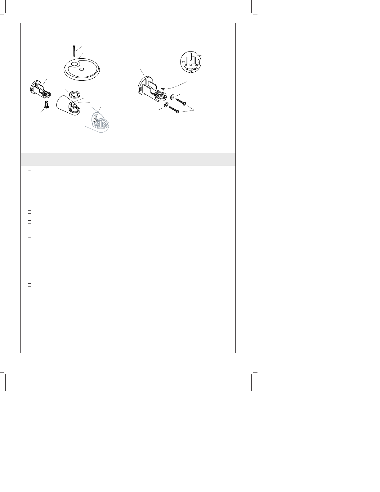
Screw
Soap Dish
Bracket
Stop
Bracket
Ring
Bottom
Housing
Tab
Washer
Front View
Washer
6. Install the Bottom Bracket
Press the bottom cover housing tab, and separate the housing
from the bracket.
Using a tape measure and level, make a pencil mark on the
finished wall exactly 22-3/4″ (57.8 cm) down from the center of
the top bracket assembly.
Push the stop out of the bracket.
Center the bracket over the mark, and mark the top and bottom
hole locations.
For tile or solid surface materials, drill a hole at the marked
locations.
Top Hole
Bottom
Hole
Screws
NOTE: Wall anchors are not required for this installation.
Attach the bracket to the finished wall with the screws and
washers provided.
Tighten securely.
Kohler Co. 7 089408-2-AC
Page 8
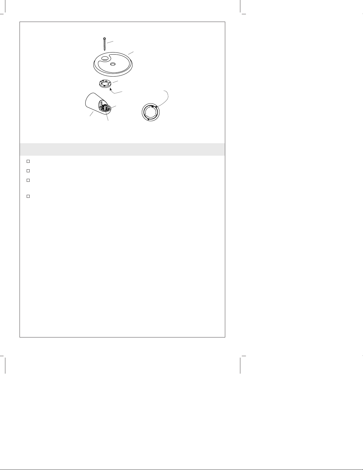
Screw
Soap Dish
Ring
Larger Indent
Housing
Tab
Bottom
Housing
Stop
Back View
7. Install the Soap Dish
Press the stop in place in the bracket.
Fit the housing over the bracket, and snap it into place.
Assemble the ring to the housing with the indent over the
housing tab.
Install the soap dish to the housing. Secure with the provided
screw.
089408-2-AC 8 Kohler Co.
Page 9
Top Housing
Notch
Button
Slide
Bar
Notch
Notch
Slide
Ring
Top Cover
Slide Bar
Soap Dish
8. Complete the Slide Bar Installation
CAUTION: Risk of product damage. Take care to avoid
scratching the soap dish with the slide bar.
Grasp the slide bar with the button and holes in bar facing up.
With the holes facing to the front and back, press the slide button
and position the slide to the right or left as desired.
Fit the top cover over the top of the slide bar.
Slip the ring over the slide bar with the tab side down.
Insert the end of the slide bar with the hole into the top housing
assembly.
Turn the slide bar until the notch engages the tab in the housing
assembly.
Move the slide bar and top housing up as far as possible.
Carefully position the slide bar into the soap dish.
Turn the slide bar slightly so it engages the soap dish tab.
Pull down on the top housing and the slide bar, and hold them
securely in place.
Securely tighten the top housing screw to ensure maximum
strength.
Assemble the ring to the top housing with the indent over the
housing tab.
Slide the top cover up and snap it firmly into place.
Kohler Co. 9 089408-2-AC
Page 10

Guide d’installation
Accessoires de douche
Outils et matériels
Perceuse et
mèches
assorties
Mètre
ruban
Niveau à
bulles
Crayon
à papier
Tournevis
cruciforme
Merci d’avoir choisi la compagnie Kohler
Nous apprécions votre engagement envers la qualité Kohler. Veuillez
prendre s’il vous plaît quelques minutes pour lire ce manuel avant de
commencer l’installation. Ne pas hésiter à nous contacter en cas de
problème d’installation ou de fonctionnement. Nos numéros de
téléphone et notre adresse du site internet sont au verso. Merci encore
d’avoir choisi la compagnie Kohler.
Avant de commencer
Respecter tous les codes de plomberie et de bâtiment locaux.
Couper l’alimentation d’eau principale.
Replacer les tubes d’alimentation ou d’évacuation si nécessaire.
Kohler Co. se réserve le droit d’apporter toutes modifications sur
le design des produits et ceci sans préavis, comme spécifié dans
le catalogue des prix.
Kohler Co. Français-1 089408-2-AC
Page 11

1. Préparer le montant de la douchette
REMARQUE : Cet accessoire ne devrait pas être installé aux
environs de 24″ (61 cm) à 48″ (121,9 cm) du sol (l’endroit critique de
support tel que défini dans ASTM F446).
Presser la languette et séparer le logement du montant.
Positionner le montant sur le mur fini, et marquer les
emplacements supérieurs et inférieurs des trous.
Percer un trou de 3/16″ à travers le carrelage uniquement pour
un montage direct sur axe.
Si un axe ne peut pas être localisé, percer un trou de 3/8″.
2. Installer les dispositifs d’ancrage
Presser et maintenir l’ensemble des pieds d’un ancrage mural
(fourni) et insérer les pieds d’ancrage mural dans l’orifice. Insérer
un ancrage mural dans chaque orifice de fixation préalablement
percé.
À l’aide d’un marteau, taper doucement sur chaque montant
mural jusqu’à ce qu’ils soient à égalité avec la surface finie du
mur.
Si le montant mural a été inséré entre deux montants, les pieds de
ce montant devront être écartés.
Pour écarter les pieds d’ancrage, insérer un objet mince et long,
tel qu’un clou de finition dans l’orifice d’ancrage mural.
Kohler Co. Français-2 089408-2-AC
Page 12

Vis
Support
Logement
Anneau
Languette
de logement
Entaille la plus large
Vis
Vis
Vue arrière
Porte-vaporisateur
3. Installer le porte-vaporisateur
Sécuriser la fixation au mur fini avec les vis fournies.
Encastrer le logement sur la fixation et presser en place.
Positionner l’anneau sur le logement avec la plus large des deux
entailles située sur la languette du logement.
Positionner le porte-vaporisateur sur l’anneau avec l’extrémité
conique de la rainure faisant face vers le bas.
Sécuriser le porte-vaporisateur à l’aide de la vis incluse.
Bien serrer. Le porte-vaporisateur devrait pouvoir pivoter.
Ajuster la vis selon le besoin.
089408-2-AC Français-3 Kohler Co.
Page 13

Support
mural
Vis
Support mural
4. Installer le support mural
REMARQUE : Cet accessoire ne devrait pas être installé aux
environs de 24″ (61 cm) à 48″ (121,9 cm) du sol (l’endroit critique de
support tel que défini dans ASTM F446).
Positionner le support mural à l’endroit désiré d’installation
contre le mur fini et marquer l’emplacement des trous des
extrémités.
REMARQUE : Percer les trous avec une mèche de 3/16″ à travers le
carrelage uniquement pour un montage direct sur axe. Si le support
n’est pas monté directement sur axe, percer les trous en utilisant une
mèche de 3/8″.
Percer un trou à chaque marque.
Si nécessaire, insérer les ancrages du mur dans les trous en
suivant les directives dans la section ″Installer les ancrages″.
Positionner le support mural contre le mur fini avec le côté
conique de la rainure vers le bas.
Sécuriser le support à l’aide des vis fournies.
Kohler Co. Français-4 089408-2-AC
Page 14

Support
Support
Logement
supérieur
Anneau
Couvercle
supérieur
Languette
Rondelle
Vis
Trou rainuré
Vue avant
Logement
supérieur
5. Installer le support supérieur
IMPORTANT ! La barre coulissante doit être montée aux support du
cadrage de l’axe aux deux extrémités. Les montants du mur ne
supporteront pas la barre coulissante.
REMARQUE : Cet accessoire ne devrait pas être installé aux
environs de 24″ (61 cm) à 48″ (121,9 cm) du sol (l’endroit critique de
support tel que défini dans ASTM F446).
Séparer le couvercle supérieur et le logement en tirant fermement.
Retirer l’anneau.
Presser la languette et séparer le logement du montant.
Positionner le support sur le mur fini et marquer l’emplacement
supérieur de l’orifice rainuré central.
Percer un trou à chaque endroit marqué.
REMARQUE : Ne pas utiliser les montants du mur.
Positionner le support contre le mur fini et l’y attacher légèrement
avec la vis et la rondelle fournies.
Encastrer le logement sur la fixation et presser en place.
089408-2-AC Français-5 Kohler Co.
Page 15

Vis
Savonnière
Support
Arrêt
Support
Anneau
Logement
inférieur
Languette
Rondelle
Vue avant
Rondelle
6. Installer le support inférieur.
Presser la languette de couverture inférieure et séparer le
logement du support.
En utilisant un mètre ruban et un niveau à bulle, faire une
marque au crayon sur le mur fini exactement à 22-3/4″ (57,8 cm)
du centre de l’ensemble de support supérieur.
Pousser l’arrêt à l’extérieur du support.
Centrer le support sur la marque, et marquer les emplacements
des trous supérieurs et inférieurs.
Pour les matériaux à surface carrelée ou solide, percer un trou
aux emplacements marqués.
Orifice
supérieur
Orifice
inférieur
Vis
REMARQUE : Les ancrages muraux ne sont pas nécessaires pour
cette installation.
Fixer le support au mur fini à l’aide des vis et rondelles fournies.
Bien serrer.
Kohler Co. Français-6 089408-2-AC
Page 16

Vis
Savonnière
Anneau
Entaille la plus large
Languette de
logement
Logement
inférieur
Stop
Vue arrière
7. Installer la savonnière
Presser l’arrêt dans le support.
Encastrer le logement sur la fixation et presser en place.
Assembler l’anneau au logement avec l’entaille sur la languette de
logement.
Installer la savonnière dans le logement. Sécuriser avec la vis
fournie.
089408-2-AC Français-7 Kohler Co.
Page 17

Encoche
Bouton
Encoche
Glissière
Logement
supérieur
Anneau
Couvercle
supérieur
Barre
coulissante
Encoche
Barre
coulissante
Savonnière
8. Vérification de l’installation
ATTENTION : Risque d’endommagement du produit. Veiller à
ne pas rayer la savonnière avec la barre coulissante.
Maintenir la barre coulissante avec le bouton et les trous faisant
face vers le haut.
Avec les trous face à l’avant et derrière, presser le bouton de
glissière et positionner la glissière à droite ou à gauche selon le
désir.
Placer le couvercle supérieur sur la partie supérieur de la barre
coulissante.
Enfiler l’anneau sur la barre coulissante avec la languette faisant
face vers le bas.
Insérer l’extrémité de la barre coulissante dans le trou au-dessus
de l’ensemble du logement.
Tourner la barre coulissante jusqu’à ce que la cannelure engage la
languette dans l’ensemble du logement.
Déplacer la barre coulissante et le logement supérieur aussi haut
que possible.
Positionner délicatement la barre coulissante dans la savonnière.
Tourner doucement la barre coulissante de manière à ce qu’elle
s’engage à la languette de la savonnière.
Kohler Co. Français-8 089408-2-AC
Page 18

Vérification de l’installation (cont.)
Tirer le logement supérieur et la barre coulissante et les maintenir
en place.
Bien serrer la vis du logement supérieur pour assurer une force
maximale.
Assembler l’anneau dans le logement supérieur avec l’entaille sur
la languette du logement.
Glisser le couvercle supérieur et l’engager en place fermement.
089408-2-AC Français-9 Kohler Co.
Page 19

Guía de Instalación
Accesorios de ducha
Herramientas y materiales
Taladro y
brocas
surtidas
Cinta
métrica
Nivel Lápiz Destornillador
de punta de
cruz (Phillips)
Gracias por elegir los productos de Kohler
Apreciamos su elección por la calidad de Kohler. Dedique unos
minutos para leer este manual antes de comenzar la instalación. En
caso de problemas de instalación o de funcionamiento, no dude en
contactarnos. Nuestros números de teléfono y nuestra página web se
encuentran en la última página. Gracias nuevamente por escoger a
Kohler.
Antes de comenzar
Cumpla con todos los códigos locales de plomería y de
construcción.
Cierre el suministro principal de agua.
Reemplace las tuberías de desagüe o suministro de ser necesario.
Kohler Co. se reserva el derecho de modificar el diseño de los
productos sin aviso, tal como se especifica en la lista de precios.
Kohler Co. Español-1 089408-2-AC
Page 20

Instale el anclaje
1. Prepare el soporte de la ducha de mano
NOTA: Este accesorio no se debe instalar en el área entre 24″ (61
cm)y48″(121,9 cm) del piso (el área de soporte crítico según se
describe en la norma ASTM F446).
Presione la lengüeta y separe el alojamiento del soporte.
Coloque el soporte sobre la pared acabada y marque la ubicación
del orificio superior e inferior.
Perfore un orificio de 3/16″ a través del azulejo, sólo para realizar
el montaje a un poste.
Si no puede encontrar un poste, taladre un orificio de 3/8″.
2. Instale los elementos de anclaje
Presione y sostenga las patas del anclaje mural (incluido), e
insértelas en el orificio. Inserte un anclaje mural en cada orificio
de fijación previamente perforado.
Golpee suavemente cada anclaje mural con un martillo hasta que
queden a ras de la superficie acabada.
Si se ha introducido el anclaje mural en un espacio entre los
postes, será necesario desplegar las patas de los anclajes.
Para desplegar las patas del anclaje, inserte un objeto largo y fino,
tal como un clavo, en el orificio del anclaje.
089408-2-AC Español-2 Kohler Co.
Page 21

Tornillo
Soporte
Alojamiento
Anillo
Lengüeta del
alojamiento
Muesca grande
Tornillo
Tornillo
Vista
posterior
Soporte del rociador
3. Instale el soporte del rociador
Fije el soporte a la pared acabada con los tornillos incluidos.
Coloque el alojamiento sobre el soporte y encájelo en su lugar.
Coloque el anillo sobre el alojamiento, de manera que la muesca
más grande esté sobre la lengüeta del alojamiento.
Coloque el soporte de rociador sobre el anillo con el extremo
estrecho de la ranura orientado hacia abajo.
Fije el soporte del rociador con el tornillo suministrado.
Apriete hasta que quede ajustado. El soporte del rociador debe
poder girar.
Ajuste el tornillo según sea necesario.
Kohler Co. Español-3 089408-2-AC
Page 22

Soporte
mural
Tornillos
Soporte mural
4. Instale el soporte mural
NOTA: Este accesorio no se debe instalar en el área entre 24″ (61
cm)y48″(121,9 cm) del piso (el área de soporte crítico según se
describe en la norma ASTM F446).
Coloque el soporte mural en el lugar deseado de instalación sobre
la pared acabada y marque la ubicación del orificio superior e
inferior.
NOTA: Perfore los orificios con una broca de 3/16″, penetrando el
azulejo sólo cuando monte directamente a un poste. Si el soporte no
se va a montar directamente a un poste, perfore los orificios con una
broca de 3/8″.
Perfore un orificio en cada lugar marcado.
De ser necesario, inserte los elementos de anclaje mural en los
orificios siguiendo las indicaciones de la sección ″Instale los
elementos de anclaje″.
Coloque el soporte mural sobre la pared acabada con el lado
estrecho de la ranura hacia abajo.
Fije el soporte con los tornillos suministrados.
089408-2-AC Español-4 Kohler Co.
Page 23

Soporte
Soporte
Alojamiento
superior
Anillo
Cubierta
superior
Lengüeta
Arandela
Tornillo
Orificio
ranurado
Vista frontal
Alojamiento
superior
5. Instale el soporte superior
¡IMPORTANTE! La barra deslizante debe estar montada a los
soportes de la estructura de postes, tanto arriba como abajo. Los
anclajes murales no podrán sostener la barra deslizante.
NOTA: Este accesorio no se debe instalar en el área entre 24″ (61
cm)y48″(121,9 cm) del piso (el área de soporte crítico según se
describe en la norma ASTM F446).
Separe la cubierta superior del alojamiento tirando de ambos.
Retire el anillo.
Presione la lengüeta y separe el alojamiento del soporte.
Coloque el soporte sobre la pared acabada y marque la ubicación
superior del orificio ranurado más cerca del centro.
Perfore un orificio en la ubicación marcada.
NOTA: No utilice elementos de anclaje mural.
Coloque el soporte sobre la pared acabada y fíjelo sin apretar a la
pared acabada con el tornillo y la arandela suministrados.
Coloque el alojamiento sobre el soporte y encájelo en su lugar.
Kohler Co. Español-5 089408-2-AC
Page 24

Tornillo
Jabonera
Soporte
Soporte
Fiador
Anillo
Alojamiento
inferior
Lengüeta
Arandela
Vista frontal
Arandela
Tornillos
6. Instale el soporte inferior
Presione la lengüeta de la cubierta inferior y separe el alojamiento
del soporte.
Utilice una cinta métrica y un nivel para marcar una señal con
lápiz en la pared acabada a exactamente 22-3/4″ (57,8 cm) desde
el centro de montaje del soporte superior hacia abajo.
Saque el fiador del soporte.
Centre el soporte sobre la señal marcada y marque la ubicación
del orificio superior e inferior.
Para los azulejos o materiales de superficie sólida, perfore un
orificio en los puntos marcados.
Orificio
superior
Orificio
inferior
NOTA: Los elementos de anclaje mural no son necesarios en esta
instalación.
Monte el soporte a la pared acabada con los tornillos y arandelas
suministrados.
Apriete bien.
089408-2-AC Español-6 Kohler Co.
Page 25

Tornillo
Jabonera
Anillo
Muesca grande
Lengüeta del
alojamiento
Alojamiento
inferior
Fiador
Vista posterior
7. Instale la jabonera
Coloque el fiador empujándolo en el soporte.
Coloque el alojamiento sobre el soporte y encájelo en su lugar.
Monte el anillo en el alojamiento, con la muesca sobre la lengüeta
del alojamiento.
Instale la jabonera en el alojamiento. Fíjela con el tornillo
suministrado.
Kohler Co. Español-7 089408-2-AC
Page 26

Muesca
Botón
Muesca
Soporte
deslizante
Alojamiento
superior
Anillo
Cubierta
superior
Barra
deslizante
Muesca
Barra
deslizante
Jabonera
8. Termine de instalar la barra deslizante
PRECAUCIÓN: Riesgo de daños al producto. Tenga cuidado de
no rayar la jabonera con la barra deslizante.
Sostenga la barra deslizante con el botón y los orificios en la barra
orientados hacia arriba.
Con los orificios orientados hacia el frente y la parte posterior,
presione el botón deslizante y coloque el soporte deslizante hacia
la derecha o izquierda, como se prefiera.
Encaje la cubierta superior sobre la parte superior de la barra
deslizante.
Encaje el anillo por la barra deslizante con el lado de lengüeta
hacia abajo.
Inserte el extremo de la barra deslizante con el orificio dentro del
montaje de alojamiento superior.
Gire la barra deslizante hasta que la ranura engrane con la
lengüeta del montaje de alojamiento.
Suba la barra deslizante y el alojamiento superior lo más alto
posible.
Coloque con cuidado la barra deslizante en la jabonera.
Gire la barra deslizante levemente, de manera que engrane con la
lengüeta de la jabonera.
089408-2-AC Español-8 Kohler Co.
Page 27

Termine de instalar la barra deslizante (cont.)
Tire del alojamiento superior y la barra deslizante hacia abajo y
sosténgalos bien en su lugar.
Apriete bien el tornillo del alojamiento superior para asegurar la
máxima resistencia.
Monte el anillo en el alojamiento superior con la muesca sobre la
lengüeta del alojamiento.
Deslice la cubierta superior hacia arriba y encájela bien en su
lugar.
Kohler Co. Español-9 089408-2-AC
Page 28

USA: 1-800-4-KOHLER
Canada: 1-800-964-5590
México: 001-877-680-1310
kohler.com
©2004 Kohler Co.
089408-2-AC
 Loading...