

Page 1

1276024-T01-D
KOHLER CHINA INVESTMENT CO., LTD NO.158, JIANG CHANG SAN ROAD,
JING'AN DISTRICT, SHANGHAI, PRC POST CODE: 200436
( ) 158 200436
Installation Guide
Kitchen WaterFiltration SystemCarafe Series
K-80021T-KP040-01R/K-80021T-KP050-01R
©©Copyright Kohler China Investment Co., Ltd. 2016
2016
Page 2
-1-
1276024-T01-D
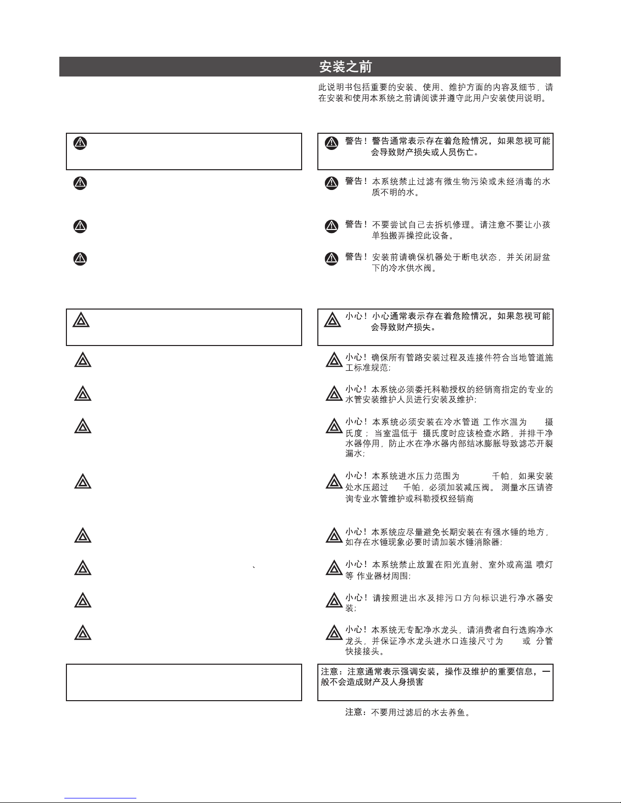
Note: Note is used to emphasize installation, operation or
maintenance information which is important, but does not
present any hazard.
!
!
!
!
!
!
!
!
CAUTION!
CAUTION!
CAUTION!
CAUTION!
CAUTION!
CAUTION!
CAUTION!
CAUTION!
Make certain that installation and
connectors must comply with all state and local
plumbing codes.
Installation and maintenance must be done
by qualified plumbing professionals designated by
dealers authorized by Kohler.
For cold water use only (Temperature
Range: 5-38 C); This filter must be protected from
freezing, which can cause cracking of the filter and
water leakage. Drain filter when room temperature
drops below 5 C.
Inlet Pressure Range: 150-400 kPa, If
water pressure exceeds 400kPa, please install
pressure limiting valve. (Please consult plumbing
professionals or dealers authorized by Kohler for water
pressure measurement).
Do not install where water hammer
conditions may occur. If water hammer conditions
exist you must install a water hammer arrester.
Do not install in direct sunlight outdoors
or where blowtorch or other high temperature sources
are nearby.
The filter must be installed with the inlet,
outlet and drain ports as labeled. Make sure not to
reverse connections.
Water filtration faucet is not supplied with
the product. you will need to purchase a water filtration
faucet with a G1/2" connector or with a 1/4" adapter.
°
°
! Note: Do not use filtered water for the water exchange
of an aquarium or a fishbowl.
CAUTION! Caution is used when failuretofollow
directions could result in damageto
equipment orproperty.
!
!
!
!
!
!
!
!
( 5-38
)5
150-400
400 (
)
(
)
G1/2 2
!
WARNING!Warning is used to indicate a hazard
which could cause injury or death if
ignored.
This document contains important information and details
concerning product installation, operation and maintenance.
Please read it carefully prior to installation and obey all the
instructions during operation.
BEFORE YOU BEGIN
WARNING! Do not use with water that is
microbiologically unsafe or of unknown
quality without adequate disinfection
before or after the system.
WARNING! Unplug the unit before your installation,
make sure cold water valve is turned off
under the sink.
WARNING! Do not repair, disassemble, or modify.
Children should be supervised to ensure
that they do not play with the appliance.
Page 3
-2-
1276024-T01-D
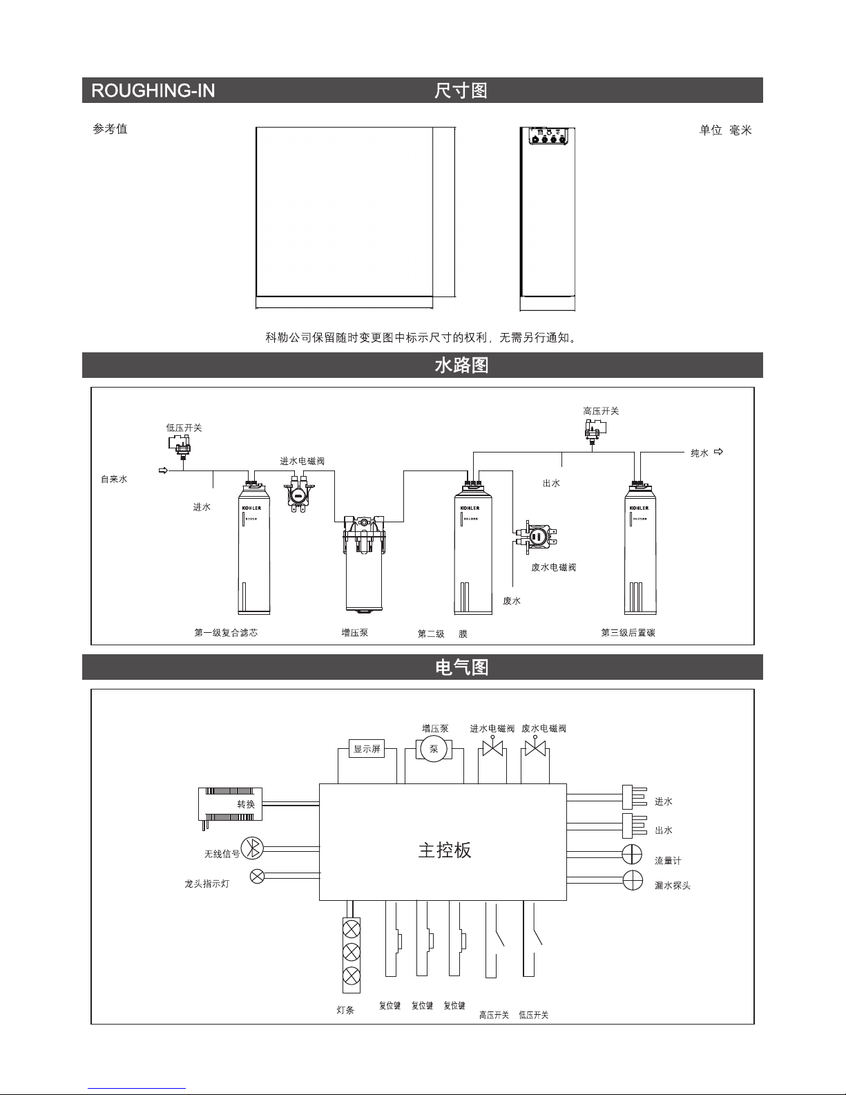
Unit: mm
:
Reference Value
Kohler reserves the right to change marked dimensions without prior notice.
482.5
462.2
149.4
Water Supply
Low Pressure Switch
Inlet TDS
TDS
Inlet Solenoid Valve
Drain Solenoid Valve
Drain
Outlet TDS
TDS
High Pressure Switch
Pure Water
Odor-Free Carbon FilterHigh Efficacy Reverse Osmosis Filter
RO
Composite Actived Carbon Filter
WATERWAY FIGURE
ELECTRICAL DIAQRAM
CompositeActivated
CarbonFilter
80031T-R1-01R
HighEfficacy Reverse
OsmosisFilter
80031T-R2-01R
Odor-Free
CarbonFilter
80031T-R3-01R
Booster Pump
AC/DC
24VDC
220VAC/50HZ
WIFI
Faucet Indicator
Led Bar
High
Pressure
Switch
Low
Pressure
Switch
Booster
Pump
Water-in
Solenoid
Valve
Drain
Solenoid
Valve
Inlet TDS
TDS
Outlet TDS
TDS
Flow Meter
Water Leak Detector
Display
Main Control Circuit Board
Reset
Button 3
3
Reset
Button 2
2
Reset
Button 1
1
Page 4

1276024-T01-D
-3-
PERFORMANCE DATA SHEETPERFORMANCE DATA SHEET
Model
Production Rate
1
1
Ratio of Product to Flush Flow
2
2
Capacity (gallon)
80021T-KP040-01R( )KP040
400 gpd (1500 / )
Standard Applications
1:1
Composite Activated Carbon Filter
80021T-KP050-01R( )KP050
INFLUENT WATER CHARACTERISTICINFLUENT WATER CHARACTERISTIC
Total Dissolved Solids
500 gpd (1900 / )
Standard Applications
1:1
1400gal (Chlorine reduction)
Total product water & drain
()
1600gal (Chlorine reduction)
Total product water & drain
()
High Efficacy Reverse Osmosis Filter
Recommendation: about 2 years
2
3
3
Recommendation: about 2 years
2
3
3
Odor-Free Carbon Filter
800gal (Chlorine reduction)
()
700gal (Chlorine reduction)
()
1 Production Rating at 40 psi, 25 C, 250 mg/L Nacl solution influent.
2 Ratio of Product to Flush Flow may vary with pressure.
3 The RO Filter performance varies depending on local water quality and product water Consumption.
1 40PSI, 250 mg/L Nacl
2
3Ro
°
1 0 - 1500 ppm(10 - 1500 mg/L)
pH
6-9
Chlorine
0 - 1 ppm (0 - 1 mg/L)
Turbidity
0-5NTU
Hardness
Limits of local standards of drinking water quality
Iron
0 - 0.5 ppm (0 - 0.5 mg/L)
Page 5
-4-
1276024-T01-D
Water Supply
Adapter
3/8" PE Tubing
3/8" PE
1/4" PE Tubing
1/4" PE
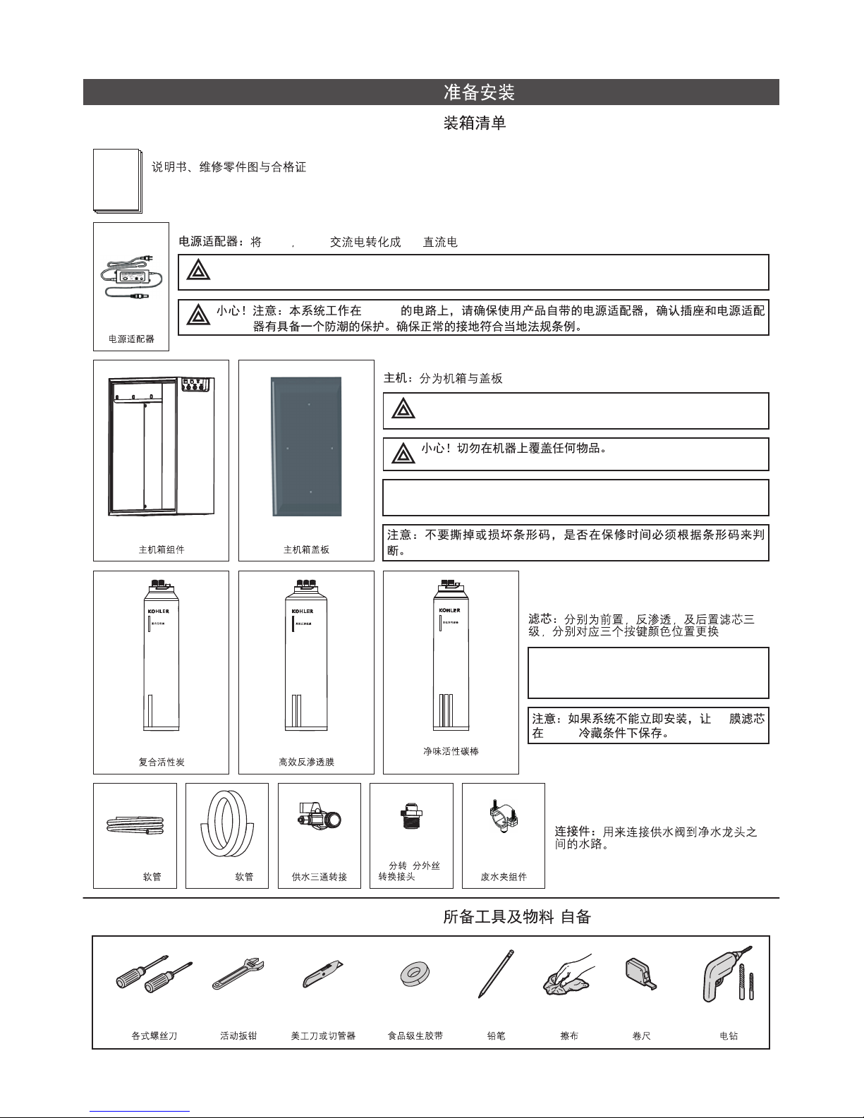
GETTING STARTEDGETTING STARTED
PackagingList
Assorted
Screwdrivers
Adjustable
Wrench
Drill
Pencil
Towels
Thread
Sealant Tape
Utility Knife or
Tube cutter
Measure Tape
Tools &Materiel required (not included)
()
Installation Guide & Service Parts Page & Compliance Certification
Power Adaper
Main Body Assembly Main Body Cover Assembly
CompositeActivated
CarbonFilter
80031T-R1-01R
HighEfficacy Reverse
OsmosisFilter
80031T-R2-01R
Composite Activated
Carbon Filter
High Efficacy Reverse
Osmosis Filter
Odor-Free Carbon Filter
Connect Fittings: Function is used to
connect the water supply valve to the
water filtration faucet.
Filter: including Pre-filter, RO, and the Postfilter 3 level, change this filters matched the
button colour
NOTE: If thesystemwill not be installed
immediately, refrigerate the RO
membrane element at 35 /40 F (2 /5 C).°° °°
RO
2/5C°°
1/4 *1/2" Male
Adapter(BSTP)
24
(BSTP)
Drain Saddle
Clamp Kit
PowerAdaper: Transform 220VAC, 50Hz into 24VDC
220V 50Hz 24V
CAUTION! Thesystemworkson24VDC electrical power only. Besure to use theincluded Power
Adapter.
24VDC
System: including Main body and Cover
CAUTION! Makesurethat the unit is not covered with
anything.
Note: DO NOT removeor destroy theserial number. It must be
referenced on request forwarrantyrepair orreplacement.
Odor-Free
CarbonFilter
80031T-R3-01R
Page 6

-5-
1276024-T01-D
Note: Please pre-install Water filtration faucet of Kohler
brand or other brands on the sink. (Refer to Water filtration
Faucet Installation Manual for tools and detailed installation
steps of water filtration faucet. For water filtration faucet
other than Kohler brand, please make sure the inlet
dimension is G1/2" or with a 1/4" adapter).
(
G1/2" 2 )
Step1 Pre-install WaterFiltration Faucet
(Refer to Figure 1- Figure 4)
(1-4)
INSTALLATION
1. Make sure cold water supply line under the sink is turned
off; (Figure 1)
(1)
2. Disconnect cold water line from threaded stub on bottom
of tap faucet; (Figure 2)
(2)
Cold Water Supply Valve
Cold Water Supply Valve
Fig.#1
1
Fig.#2
2
Stub of Tap Faucet
3. Screw the water supply adapter - female threaded stub
to the cold water supply valve male threads as shown.
Hand it tighten and snug with wrench. Screw the female
threaded tap faucet stub to the water supply adapter;
(Figure 3)
(3)
Fig.#3
3
Stub of Tap Faucet
Water Supply Adapter
4. Screw 1/4" x 1/2" Male Thread Faucet Adapter to the
female threaded Water filtration faucet stub, Hand it
tighten and snug with wrench. (Figure 4)
24
(4)
Fig.#4
4
Note: When using a wrench tight the plastic adapter, be
sure softly, if overexert, the adapter would be damaged.
,
Water Filtration Faucet Stub
1/4" X 1/2" Male Thread Faucet Adapter
24
Page 7

-6-
1276024-T01-D
Note: Cut tubing straight with a utility knife, make sure there
are no cuts, nicks, flat spots or sharp edges as figure 5, If
any of these are present, cut the tubing again; Do not kink
tubing. ( Figure 6)
(6)
Step2:Makingconnections
! Refer to Figure 5, insert the 3/8" Plastic tubing into the
filter inlet port and the water supply adapter, insert the
1/4" Plastic tubing into the filter outlet port and the end of
the Water filtration faucet; Then insert the a 1/4" Plastic
tubing into the Drain port of RO system and the Drain line
under the sink. (Figure 5)
TubingConnectors
! 53 2
RO
(5)
Fig.#5
5
Fig.#6
6
Tap Faucet
Water Filtration Faucet
Drain Saddle Clamp Kit
1/4" x 1/2" Male Thread Faucet Adapter
24
1/4" Plastic Tubing-Product Water
2
Water Supply Adapter
Cold Water Supply Valve
1/4" Plastic Tubing-Drain Water
2
3/8" Plastic
Tubing-Raw Water
3
Hot Water Supply Valve
Not Apply In This System
Not Apply In This System
Electronic Faucet Signals
(Only with Matchable Faucet)
()
Power
Drain Water (1/4")
(2 )
Product Water (1/4")
(2 )
Raw Inlet (3/8")
(3 )
Connections to undersink plumbing can be
made with a saddle clamp designed to
accept the drain tubing from the RO
system. Kohler offers a saddle kit, PN
1275904, designed for 40mm undersink
drain plumbing (Figure 13).
RO
1275904 40mm
Besuretocheck and follow local
plumbingcodes prior to installation.
Correct Cut
Incorrect Cut
Note: It may be difficult to release the tubing due to water
pressure when replacing service parts. In this case, please
shut off the cold water supply valve, turn on the Water
filtration faucet to depressurize and then try to release the
tubing again.
Fig.#7
7
To Attach Tubing
Push tubing in as
far as it can go
Tubing must be inserted
past O-ring and hit
backstop
O
Insert the locking clip
1
2
3
Fig.#8
8
To Release Tubing
Pull out locking clip Push in collect to release tubing.
With collect held, pull tubing straight out.
1
2
3
The Carafe system features reliable and convenient push-to-connect tubing connectors. Tubing is easily connected and
disconnected from these fittings as follows. (Figure 7 and 8)
(7 8)
Figure
Page 8

-7-
1276024-T01-D
NOTE: Before changing the filter, please make sure the cold
water valve is turned off.
NOTE: After the filter is replaced, the corresponding button
can be reset only. If not, the filter life indicator can't be
accurate. No need to reset after the first installation.
NOTE: Filtration performance varies depending on local
water quality.
Step3: InstallingFilterCartridge &ReplacingFilter
Cartridges
Fig.#9
9
!
!
!
Remove and discard the dustproof cap (sanitary
protective cap) from the cartridge;
Verify both O-rings are present and positioned correctly in
the grooves;
Push the filter cartridge into the filter base align the hollow
icon of the cartridge with the hollow icon on the filter base,
then turn cartridge clockwise until the hollow icon of the
cartridge were aligned the color filled icon on the filter
base, it will be fully installed. (Figure 9)
!
!
!
O
90
(9)
Rotate 90 degree & Pull out the old filter.
90
Change new filter matched the button colour.
Aim at the dot, rotate 90 degrees to fix.
90
Fig.#10
10
! When filters replaced remember to push and hold the
corresponding reset button to the filter for 5 seconds until
the indicator automatically with 2 short beep, then
corresponding orange LED light turn to white. (Figure 10)
! Please replace filter when prompted by the indicator.
!
5
( 10)
!
System Model
K-80021T-KP040-01R K-80021T-KP050-01R
First Stage
80031T-R1-01R 80041T-R1-01R
Second Stage
80031T-R2-01R 80041T-R2-01R
Third Stage
80031T-R3-01R 80041T-R3-01R
Press RESET button
for 5 seconds to reset
RESET 5
Page 9

-8-
1276024-T01-D
Fig.#11
11
Step4:Start-Up
CAUTION! If the powercord from thetransformer
to the unit looksorbecomes damaged,
the cord and transformer should be
replaced by a KohlerService Agent or
similarlyqualified person in order
to
avoid a hazard.
CAUTION! Do not touch the powerplugwith a wet
hand.
CAUTION! Do not connect and pull out the power
plugrepeatedly.
CAUTION! If ourproduct producesastrange
noise or odd smell, immediately
unplugfrom the electrical outlet and
call ourService Center.
1. Connect all electrical power;
2. When the first stage filter is brand new / replaced (must be
reset first), the system will do washout 5 minutes to get it
ready for making clean water. And the indicator light will
be waterfall effect. Make sure the filtration faucet be
turned off. (Figure 11)
1.
2.
5
( 11)
Note:Please confirm supplywater inlet
pipe & drain pipeisalreadyconnected,
thesystemwill automatically start
washing and drainingbefore
connectingpowerwhen thesystem is
brand new.
3. When the second stage RO-filter or the third stage carbon
block filter is brand new / replaced open the waterfiltrion
faucet , then run product water for a minimum 30 minutes
through the waterfiltration faucet to flush out any
remaining impurity & carbon dust from the RO & post filter.
3. 30
RO ,
Note: The initial product water can't be used as drinking or
cooking water.
Step5:Test System
!
!
Turn off the water filtration faucet, Keep the cold water
supply valve turned on. Check all fittings and tubings for
leaks. If it leaks, see Troubleshooting.
Complete the installation and cleanup.
!
!
Page 10

1276024-T01-D
-9-
TDS In
TDS
TDS Out
TDS
The first stage filter
pertormance indicator
The second stage filter
performance indicator
The third stage filter
performance indicator
PERFORMANCE INDICATOR
PRODUCE: When first time Start-up procedure is finished,
each time open the water filtration faucet to get the pure
water in&out water TDS value will light on shut off the
faucet, all lights black out
When filter life is running low or out each time open the
filtration faucet filter LEDs will change to orange with
normally lighting on or blinking.
TDS
LED
()
Plug in
!
!
!
!
Plug ICSelf-test Status:
Diagnosis Succeeded When
the user plug power into the
device, the IC self-test will be
automatically conducted. When
it is processing the self-test, the
LED displays looped "single
dash" with one short beep.
IC
IC
,
!
!
!
!
Status:Produce well
When produce the pure water
with performance well filters,
the filter indicator will be white
&the TDS value be displayed.
/
,
TDS
!
!
!
!
!
!
Washout
When the first stage filter is
brand new/replaced or the
system after every 24 hours
working, the system will do
washout to get it ready for
making clean water.
If power cut during the
washout, it will continue
washout until time over when
plug the power again.
/
24
515
,
!
!
!
!
FilterStatus:Filter lifeis
running low/ less than 10%
Filter LEDs will change to
orange with 3 short beep as
the filtration faucet is ON
when its life is running low/
less than 10% left. (Users
need to replace filters and
reset the indicator, and then
the LED turns white right after
the reset.)
10%
10%
!
!
!
!
FilterStatus: Immediate
change needed
Note:
Orange LED starts blinking
when the filter run out and
needs to be change
immediately when users turn
the filtration faucet ON, it
comes with 0.2 sec repeating
short beeps. (Users need to
replace filters and reset the
indicator, and then the LED
turns white right after the reset.)
TDS reduction problem
will blink orange LED with 3
short beep.
/
,
0.2 0.2
RO
Washout Normal
Expiration notice Expiration notice
Page 11

1276024-T01-D
-10-
ERROR: When system error is detected, the influent water
TDS value LED change to display an "Err" symbol, and the
effluent water TDS value LED will display an error code to
show a type of errors.
TDS LED "Err"
TDS
System Alarm (One long beep)
!
!
!
!
Error 02: EEPROM
02
The TDS indicator displays "Err
02" with System Alarm (One
long beep)when the system
self-diagnosis failed.
Err
02
EEPROM
!
!
!
!
Error 04: Disconnected TDS
outlet
04 TDS
Display "ERR" before "TDS IN"
and "04" before "TDS OUT"
when users turn the filtration
faucet on, it comes with 3
repeating short beeps. It means
the TDS outlet is not connected.
Err
04
TDS
!
!
!
!
Error 03:Disconnected TDS
inlet
03 TDS
Display "ERR" before "TDS
IN" and "03" before "TDS
OUT" when users turn the
filtration faucet on, it comes
with 3 repeating short beeps.
It means the TDS inlet is not
connected.
Err
03
TDS
!
!
!
!
Error 01: Leaking issue
01
When the leaking issue
occurs, system will shut down,
the TDS indicator will display
"Err 01" on your machine
when users turn the filtration
faucet on, it comes with a
repeating long beeps. Please
eliminate the leaking issue
follow the Troubleshooting.
Err
01
!
!
!
!
Error 05: Insufficient feed
waterpressure.
05
Display "ERR" before "TDS
IN" and "05" before "TDS
OUT" when feed water
pressure is Insufficient.
Err
05
!
!
!
!
Error 06:Pump Overused >40
Mins
06
40
Display "ERR" before "TDS IN"
and "06" before "TDS OUT" . It
means the pump is overused
more than 40 Mins.
Err
06
System Alarm (3 short beeps)
System Alarm (3 short beeps)
Page 12

1276024-T01-D
-11-
!
!
!
!
Error 08: Displaypanel is not
connected with PCB.
08
Display "ERR" before "TDS IN"
and "08" before "TDS OUT" . It
means the display panel have
communication problem with
PCB.
Err
08
!
!
!
!
Error 07: Pump malfunction
Display "ERR" before "TDS
IN" and "07" before "TDS
OUT". It means the pump
malfunction.
07
Err
07
!
!
!
!
Error 09: Unusual Pump
Start
09
Display "ERR" before "TDS
IN" and "09" before "TDS
OUT". It means unusual
pump start.
Err
09
System Alarm (3 short beeps)
System Alarm (3 short beeps)
Important Information in Using the System:
A period of time after the system shutoff, the product
water TDS value will be higher in less time, this is a
normal condition, just to discharge a small amount of
product water;
(System Alarm is a natural concomitant of this condition ,
if the alarm disappeared after producing the water a
minute later , system do not need any treatment;)
Before prolonged periods of non-use (such as during a
vacation) it is recommended that the cold water supply
valve be turned off. If it is more than one week, please
flush the filter thoroughly for at least 5 minutes before
reusing it;
If leaks occur and persist on system, please first turn off
the water supply valve. Call Kohler -Free Technical
Support line directly or your local distributor authorized by
Kohler;
Local water conditions and actual volume of water can
affect filter life. Be sure to replace the cartridge when
prompted by the performance LED indicator.
!
!
!
!
!
!
!
!
!
!
TDS
(RO
1)
()
15
OPERATION INSTRUCTIONS
Page 13

1276024-T01-D
WARING!Electrical shock hazard!Unplug the unit before maintaining.
-12-
TROUBLESHOOTINGGUIDE
Problem
Possible Cause
Remedy
"Err1"
"Err2"
"Err3"
"Err4"
"Err5"
"Err6"
"Err7"
"Err8"
"Err9"
Filter LEDs will change
to orange with beeps
Unit fails to initiate
Low or No faucet flow
Tubing not fully seated in fitting.
Self-diagnosis failed, EEPROM error.
TDS inlet not connected.
TDS outlet not connected.
Insufficient feed water pressure.
Pump Overused >40 Mins.
Pump malfunction.
Display panel is not connected with PCB.
Unusual Pump Start.
Filter life is running low or out.
No power supply.
Filter blockage caused by poor water quality.
Power adapter failure.
Pump or Solenoid Valve failure.
The Inlet TDS led indicator show waterfall effect,
and the system do washout.
Check all fittings for tightness.
Contact Kohler service.
Contact Kohler service.
Contact Kohler service.
Change in line pressure.
Repeat unplug and plug once.
Contact Kohler service.
Contact Kohler service.
Check all fittings tiny leakage or not.
Change in line pressure; or wait for the water
pressure change to normal.
Check the filtration faucet closed tightly or not.
Replace filter element.
Plug in again.
Check and Replace filter.
Contact Kohler service.
Contact Kohler service.
Turn off the faucet, wait for the washout finished.
Tubing abraded in seal area. Recut tubing and redo connection.
System inside leakage. Contact Kohler service.
Note: all the leakage (including not the system
leakage) could be detected and system will force
shutdown.
Note: after above steps, please unplug the
power first ,then wipe & dry the water leakage
protector sensor, plug in the power again.
"Err1"
"Err2"
"Err3"
"Err4"
TDS
TDS
"Err5"
"Err6"
"Err7"
"Err8"
40
"Err9"
,
NOTE: Should service, adjustment or trouble-shooting information be needed which is not covered in the Use Guide,call
yourKohlerDealer.
Page 14

1276024-T01-D
-
-
80021T-KP040-01R( )KP040 80021T-KP050-01R( )KP050
220V/50Hz
70W
1.05L/min
3800L
75W
1.31L/min
3900L
5-38
0.15-0.4Mpa
Q31/0108000050C001
(2015) 0123
()
302-303 307-308
 Loading...