

Page 1
Installation and Care Guide
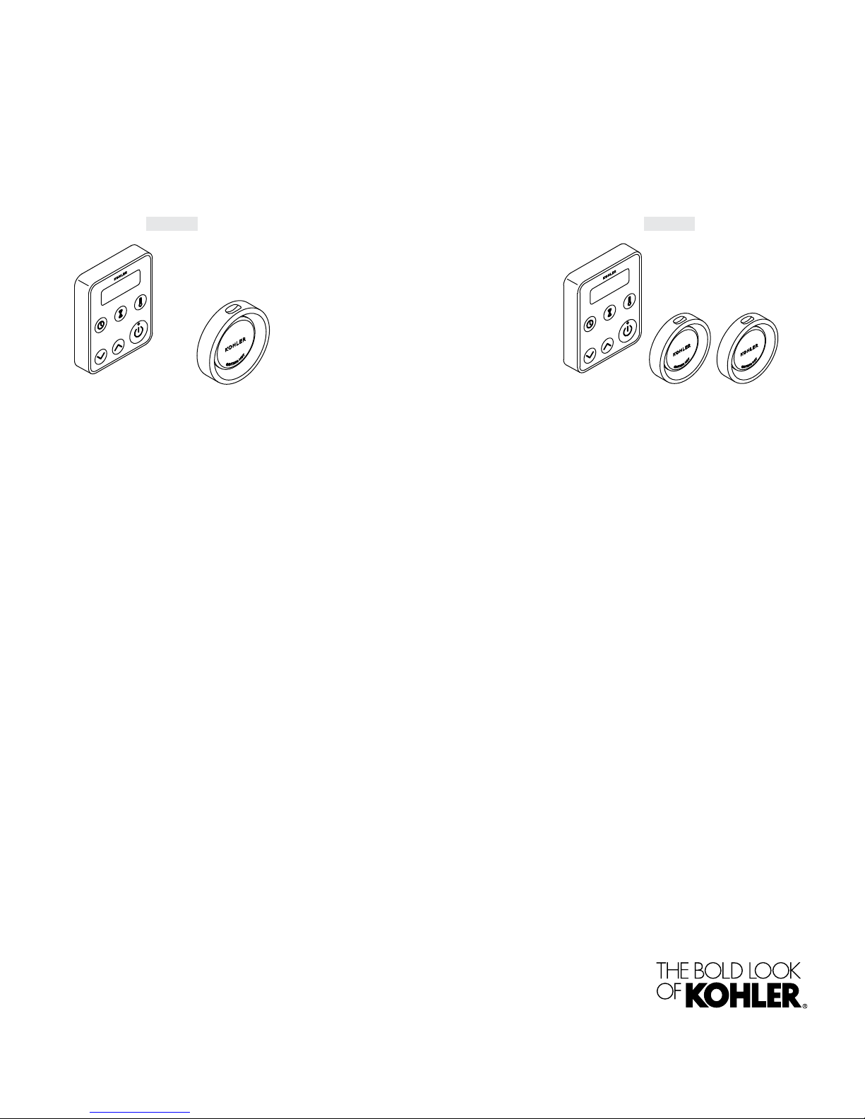
Steam Control Kit
K-5557 K-5558
M product numbers are for Mexico (i.e. K-12345M)
Los números de productos seguidos de M corresponden a México
(Ej. K-12345M)
Français, page “Français-1”
Español, página “Español-1”
1230489-2-C
Page 2
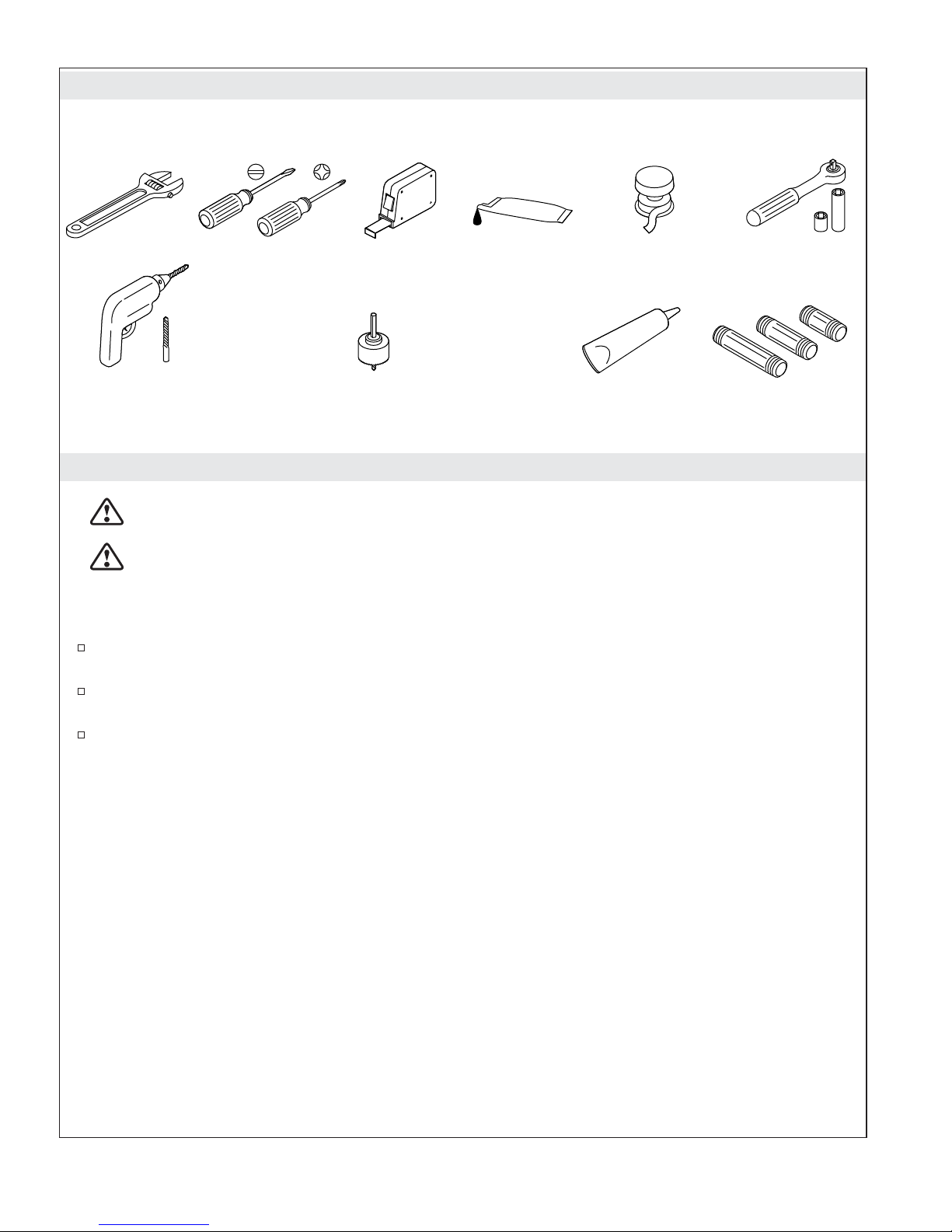
Tools and Materials
Socket Wrench
with 1" Socket
Pipe Nipples
Drill w/
1/4" Drill Bit
1-1/4" & 2-1/2" Hole Bit
(match bit to wall material)
Silicone
Lubricant
Silicone Sealant
Sealant
Tape
Before You Begin
CAUTION: Risk of electrocution. Disconnect the electricity to the working area at the main
breaker panel before performing these installation steps.
CAUTION: Risk of allergic reaction. Before adding any oils, aromatic therapies, or skin care
products to the aromatherapy well, make sure they will not cause an allergic reaction to the user.
NOTICE: Use this unit only for its intended use as specified in this manual. DO NOT use attachments
not recommended by Kohler Co.
Inspect the product for any shipping damage. Do not install the unit if it is damaged. Contact the
Kohler Co. Customer Care Center using the information on the back of this guide.
Follow all local plumbing and electrical codes. All electrical work should be done by a qualified
electrician.
Disconnect all power before making any electrical connections.
1230489-2-C 2 Kohler Co.
Page 3
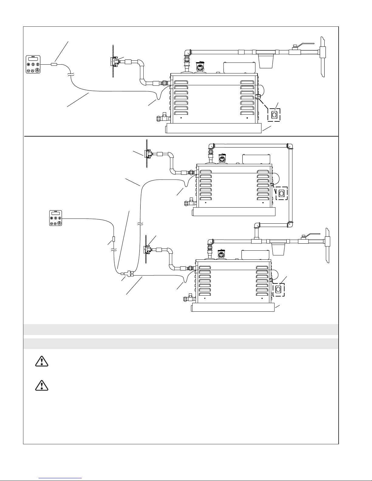
Connector, RJ12 Double Female (Assembled to Control Cable)
UIC
Control Cable
50' (15.2 m) White, Crossover
Steam Head and
Housing Assembly
Cable Data 6P/6C
78" (1981 mm)
Black, Straight Through
Steam Head and
Housing Assembly
Steam Generator
Control Cable Input
Drip Loop
Drain/Spill Pan
Control Cable
50' (15.2 m)
White, Crossover
UIC
Connector, RJ12 Double
Female(Assembled to
Control Cable)
Coupler 3-Way Straight
Cable Data 6P/6C
10" (254 mm)
Black, Straight Through
Layout Options
1. Review the Layout
CAUTION: Risk of personal injury. Do not install the Steam Control User Interface outside the
steam enclosure. The User Interface must be installed within the enclosure to allow the sensors to
regulate the temperature and control the flow of steam.
Drip Loop
Steam Head and
Housing Assembly
Drip Loop
Steam Generator
Control Cable
Input
Drain/Spill Pan
CAUTION: Risk of scalding. Do not locate the steam head near a seat or bench, as the steam head
is hot during operation and may scald the user if touched.
NOTICE: The user interface should be mounted on the wall opposite the steam head. The steam head
should always be located as far away from the seating area as possible.
NOTICE: Locate the steam head 6″ (152 mm) above the floor and a minimum of 4-1/2″ (114 mm) from
the threshold.
Kohler Co. 3 1230489-2-C
Page 4
Review the Layout (cont.)
Review the layout determined during the steam generator installation. See the steam generator installation
guide for more information.
Install the steam control user interface inside the steam enclosure.
Determine the steam head location or locations (for dual steam generator installations).
Ensure clearance between the steam line and any surrounding surfaces.
1230489-2-C 4 Kohler Co.
Page 5
Provide clearance
from wall.
Wall Stud
Mark the nipple even
with finished wall.
Temporary
Nipple
6" (152 mm) from Floor
2-1/2" (64 mm)
Wall Stud
2. Prepare the Site
NOTE: This section continues the installation described in the steam generator installation instructions.
Refer to the steam generator installation instructions for more information, if needed.
NOTE: If two steam heads are used, there must be at least 12-1/2″ (318 mm) between the center of each
hole. The steam heads do not need to be located on the same wall. Two steam heads can be mounted on
different walls to improve steam distribution.
Install the finished wall.
Drill or cut a 2-1/2″ (64 mm) hole centered around the elbow in the wall.
Mark the temporary pipe nipple at the finished wall surface.
Remove the temporary pipe nipple from the elbow.
Kohler Co. 5 1230489-2-C
Page 6
Wall
1/2" Elbow
Nipple
Lubricate
O-rings.
Gasket
Steam Head Housing
Lip
Aromatherapy Well
Steam Head
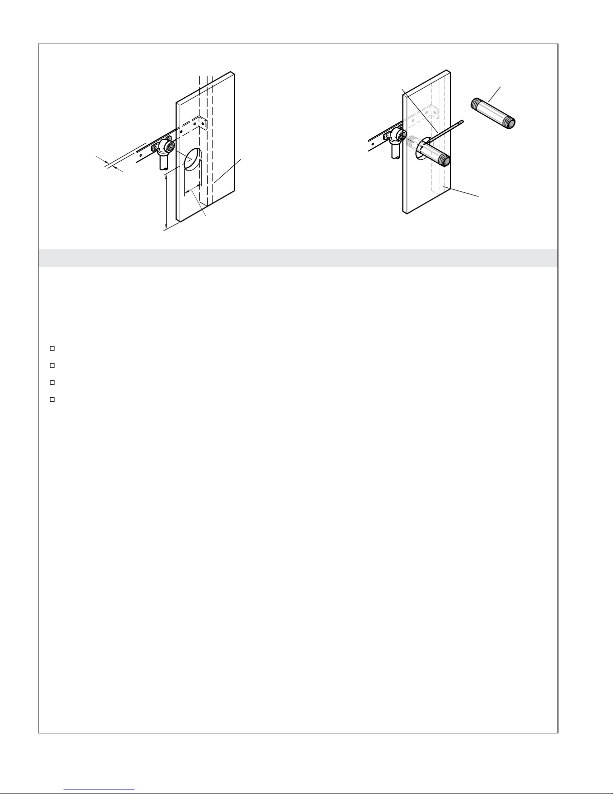
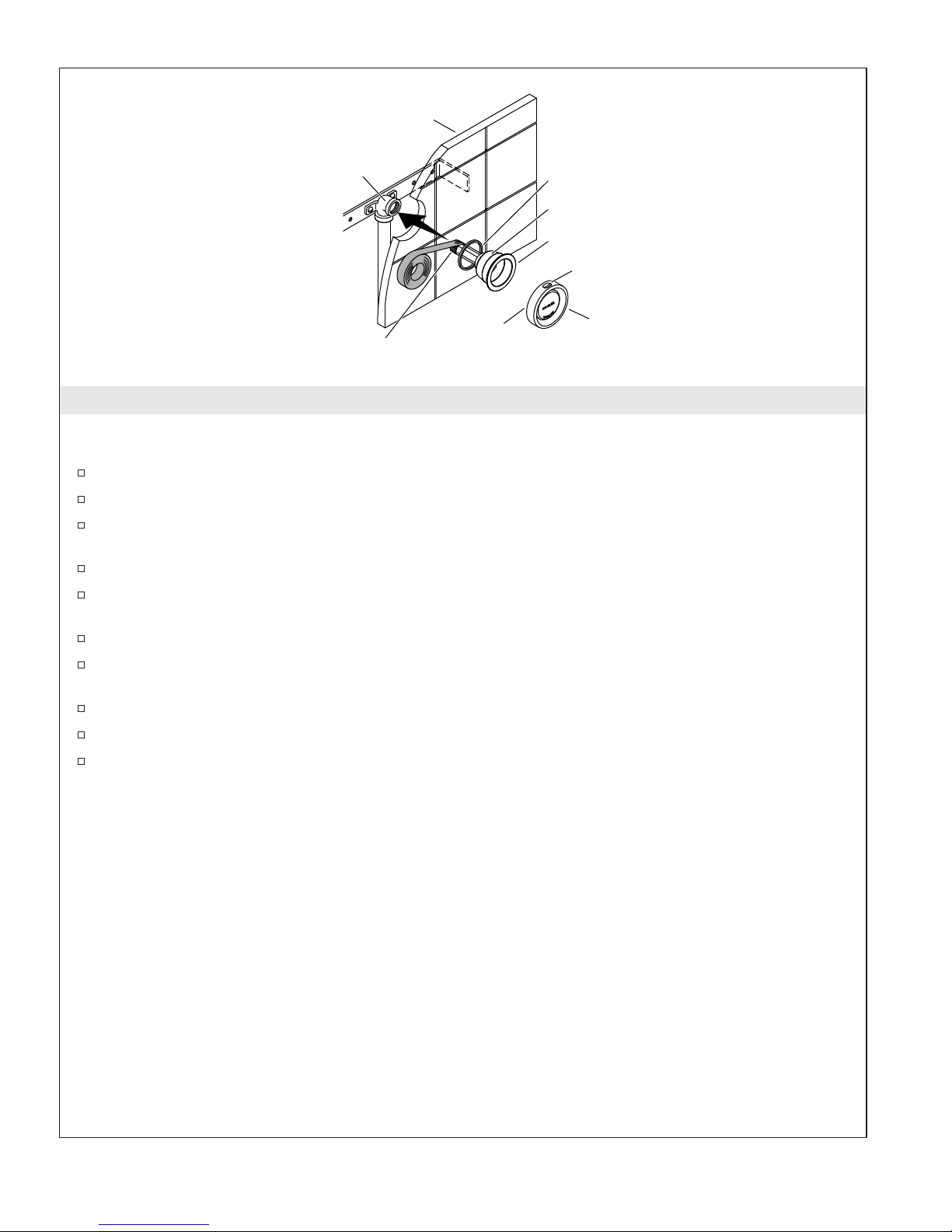
3. Install the Steam Head(s)
NOTICE: Do not obstruct the steam head with shut-off valves, plugs, or caps.
Subtract 1-1/4″ (32 mm) from the marked length to determine the appropriate nipple size.
Choose a nipple length within 1/8″ (3 mm) of the appropriate nipple size.
Apply thread sealant to one end of the nipple and thread that end into the steam head housing
until hand-tight.
Apply thread sealant to the other end of the nipple.
Position the gasket around the steam head housing so that it will be between the finished wall and
the steam head housing flange.
Usea1″ socket to thread the steam head housing assembly into the elbow in the wall.
Make sure the gasket is compressed and a good seal has been achieved around the edges of the
steam head housing.
Use an appropriate sealant to achieve a watertight seal if needed.
Apply silicone lubricant to the steam head O-rings.
Carefully press the steam head assembly into the steam head housing with the aromatherapy well
positioned on the top of the steam head.
1230489-2-C 6 Kohler Co.
Page 7
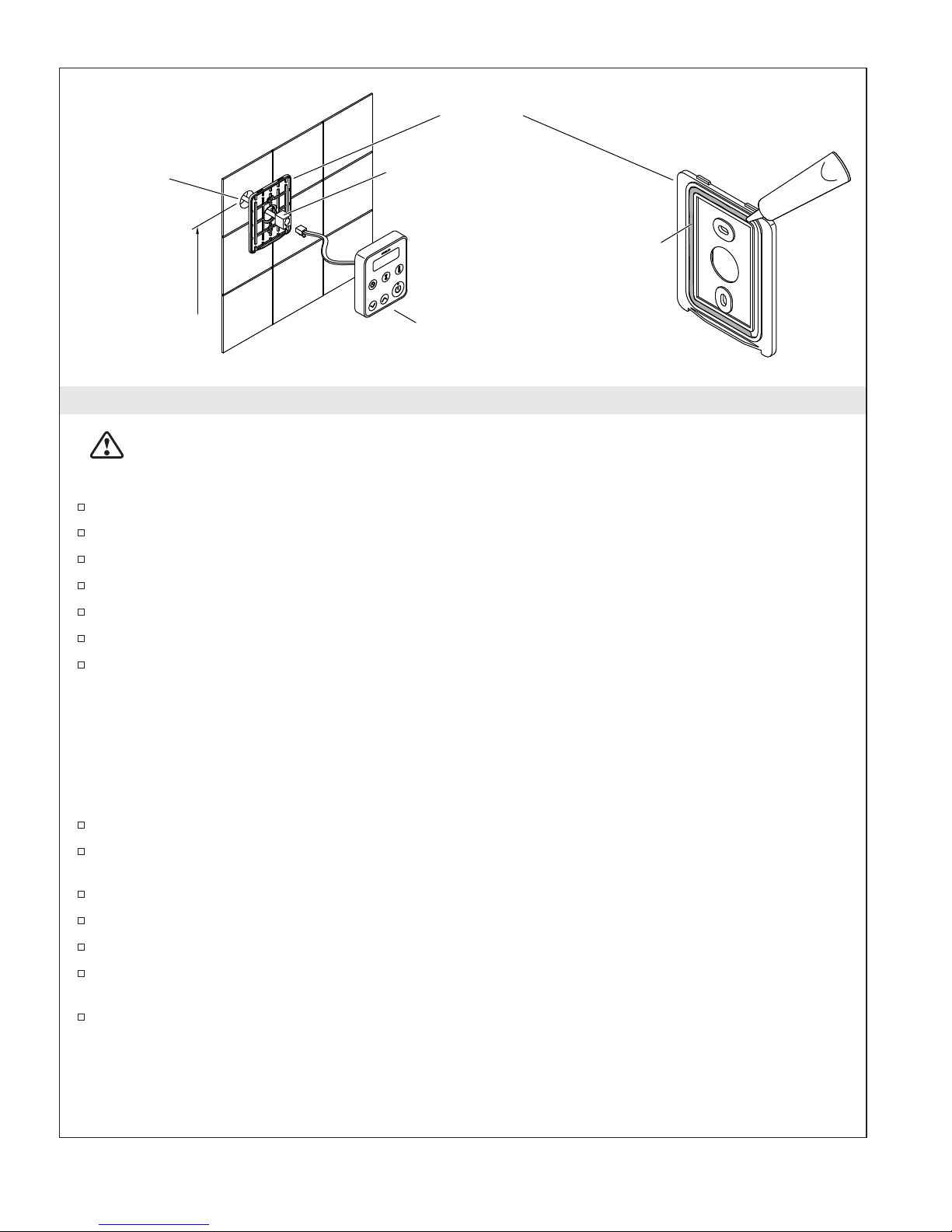
Wall Mount
Back View
Ø 1-1/4"
(32 mm)
Control Connector
Apply silicone sealant
to groove.
60" (1524 mm)
to Floor
Control Pad
4. Install the Steam Control
WARNING: Risk of personal injury. Do not install the Steam Control User Interface outside the
steam enclosure. The User Interface must be installed within the enclosure to allow the sensors to
regulate the temperature and control the flow of steam.
Make sure that the power is turned off at the main breaker panel before proceeding.
Locate the control pad on the wall 60″ (1524 mm) from the floor.
At the selected location, drill a hole 1-1/4″ (32 mm) in diameter.
Center the wall mount on the 1-1/4″ (32 mm) hole, and mark the screw hole locations.
Use a 1/4″ drill bit to drill holes for the wall anchors at the marked locations.
Insert the wall anchors into the holes.
Apply a continuous bead of silicone sealant in the groove on the back side of the wall mount, and
secure the wall mount with the screws provided.
NOTICE: Do not pinch, nail, wedge, or use undue force when handling the control connector and the
control pad wire. Any damage may result in control kit failure. If the control pad is not installed
immediately, protect the control connector with tape or other shielding material.
NOTICE: When installing the control kit, allow room in the control cable for a drip loop. The drip loop
will discourage moisture from following the control cable to the steam generator.
Pull the steam control connector and cable from the steam generator through the drilled hole.
Carefully plug the control connector to the control pad wire using the double-end female connector
(provided).
Snap the control pad onto the wall mount.
Restore the power at the main breaker panel.
Turn on both water and power to the steam generator.
Test the control pad to ensure it is functioning properly. Refer to the ″Operating the Steam Control″
section.
Allow the silicone sealant to cure for 24 hours before use.
Kohler Co. 7 1230489-2-C
Page 8
Display
Clock
Timer
Temperature
Decrease
Power
Increase
5. Operate the Steam Control
Steam Control Operation
NOTE: The clock is always displayed when the steam generator is not in use.
Press the ″Power″ button to start the steam generator.
When the ″Power″ button is pressed the green light on the button turns on. The light remains on
until the unit is turned off. The display reads ″On″ for the first 3 minutes of operation if the settings
are not changed.
Press the ″Power″ button again to turn off the steam generator. The green light on the ″Power″
button will turn off and the display will read ″Off″ for 5 seconds, and will then return to display the
clock.
NOTE: When the unit is turned on, the steam duration and temperature settings will be those of the
previous user’s settings. A new steam control unit comes pre-set to operate at 113°F (45°C) for 15 minutes.
Steam Control Operation
NOTE: Make sure the steam control unit is turned on before making any of the following adjustments.
Press the ″Temperature″ button and the display will flash the previous temperature setting. To
adjust the steam room temperature, press the ″Increase″ or ″Decrease″ buttons to raise or lower the
steam room temperature. The maximum allowable temperature is 125°F (52°C), and the minimum
operating temperature is 90°F (32°C).
After 5 seconds, the flashing will stop and the room temperature will be displayed as it changes to
the target temperature.
Press the ″Timer″ button and the display will flash the previous run time setting. Press the
″Increase″ or ″Decrease″ buttons to adjust the time setting higher or lower. After 5 seconds the
flashing will stop and the timer setting will be displayed. If the ″Increase″ or ″Decrease″ buttons are
not pressed the time will continue to count down. The minimum operating time is 10 minutes, and
the maximum time allowed is 20 minutes.
Press the ″Clock″ button and the display will flash the currently set time of day. Press the ″Increase″
or ″Decrease″ buttons to adjust the time of day. After 5 seconds the display will stop flashing and
the set time will be displayed.
Press the ″Power″ button to stop the steam generator and exit the steam room at any time. The
display will read ″Off″ for 5 seconds and then default to the set clock time.
Change the temperature reading between Fahrenheit and Celsius by pressing and holding the
″Temperature″ button for 3 seconds.
Power Clean Function
1230489-2-C 8 Kohler Co.
Page 9
Operate the Steam Control (cont.)
WARNING: Risk of personal injury. Steam room temperatures will be extremely high when the
power clean function is activated. Do not enter the steam room while the power clean function is in
progress.
IMPORTANT! The user will be automatically instructed to activate the power clean function after 600
minutes of steam generator use. The display will read ″run″″PCLn.″ The steam generator may be used
three times after the ″run″″PLCn″ message is delivered and then the steam generator will not operate
until the power clean cycle has been completed.
NOTE: Water will typically discharge from the steam head when the power clean function is activated.
This is normal operation during the power clean cycle.
NOTE: The power clean cycle must be entirely completed before normal steam generator operation can be
resumed.
To activate the power clean function, simultaneously press the ″Timer,″″Increase,″ and ″Decrease″
buttons and hold them down for 5 seconds. The display will read ″PCLn,″″On,″ and then count
down the power clean function cycle time until the cleaning process is complete. The cleaning cycle
may last up to 45 minutes and will shut off automatically when complete.
NOTE: If electrical power to the steam generator is interrupted during the power clean function, the
power clean cycle will need to be restarted after electrical power has been restored.
Care and Cleaning
For best results, keep the following in mind when caring for your KOHLER product:
•
Always test your cleaning solution on an inconspicuous area before applying to the entire surface.
•
Wipe surfaces clean and rinse completely with water immediately after applying cleaner. Rinse and
dry any overspray that lands on nearby surfaces.
•
Do not allow cleaners to soak on surfaces.
•
Use a soft, dampened sponge or cloth. Never use an abrasive material such as a brush or scouring
pad to clean surfaces.
For detailed cleaning information and products to consider, visit www.kohler.com/clean. To order Care &
Cleaning information, call 1-800-456-4537.
Warranty
KOHLER Steam Generator
THREE-YEAR LIMITED WARRANTY
Kohler steam generator units manufactured after September 15, 2001, are warranted to the original consumer
purchaser to be free of manufacturing defects in material and workmanship during normal residential usage
for three (3) years from the date of installation. This warranty only applies to KOHLER steam generator units
installed in the United States of America, Canada or Mexico (″North America″).
If a defect is found in normal residential usage, Kohler Co. will, at its election, repair or replace the unit, or
make appropriate adjustment. Damage caused by accident, misuse or abuse is not covered by this warranty.
Proof of purchase (original sales receipt) must be provided to Kohler Co. with all warranty claims. Kohler
Co. is not responsible for labor charges, removal charges, installation, or other consequential costs. In no
event shall the liability of Kohler Co. exceed the purchase price of the unit.
If this unit is used commercially or installed outside of North America, Kohler Co. warrants the unit to be
free from defects in material and workmanship for one (1) year from the date of installation with all other
terms of this warranty applying except duration.
To obtain warranty service contact Kohler Co., either through your Dealer, Plumbing Contractor, Home
Center or E-tailer or by writing Kohler Co., Attn: Customer Care Center, 444 Highland Drive, Kohler, WI
53044, USA, or by calling 1-800-4-KOHLER (1-800-456-4537) from within the USA and Canada, and
Kohler Co. 9 1230489-2-C
Page 10
Warranty (cont.)
001-800-456-4537 from within Mexico, or visit www.kohler.com within the USA, www.ca.kohler.com from
within Canada, or www.mx.kohler.com in Mexico.
KOHLER CO. AND/OR SELLER ARE PROVIDING THESE WARRANTIES IN LIEU OF ALL OTHER
WARRANTIES, EXPRESSED OR IMPLIED, INCLUDING BUT NOT LIMITED TO THE IMPLIED
WARRANTIES OF MERCHANTABILITY AND FITNESS FOR A PARTICULAR PURPOSE. KOHLER CO.
AND/OR SELLER DISCLAIM ANY LIABILITY FOR SPECIAL, INCIDENTAL OR CONSEQUENTIAL
DAMAGES. Some states/provinces do not allow limitations on how long an implied warranty lasts, or the
exclusion or limitation of special, incidental or consequential damages, so these limitations and exclusions
may not apply to you. This warranty gives you specific legal rights. You may also have other rights, which
vary from state/providence to state/providence.
This is Kohler Co.’s exclusive written warranty.
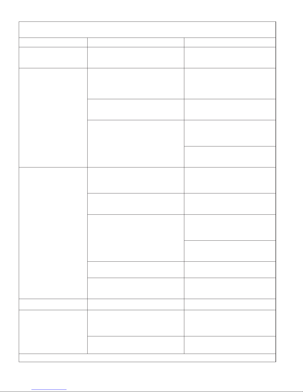
Troubleshooting
NOTE: The troubleshooting steps primarily apply to the steam control. For steam generator issues refer to
the ″Troubleshooting″ section in the steam generator installation instructions.
NOTE: For service parts information, visit your product page at www.kohler.com/serviceparts.
This troubleshooting guide is for general aid only. For service and installation issues and concerns, call
1-800-4KOHLER.
Symptoms Probable Causes Recommended Action
1. Error 1, 2, 3, 4, 7, or 8
is displayed.
2. Error 5 is displayed. A. Tank water level is too low (green
3. Error 6 is displayed. A. The user interface is installed too
4. Display is blank. A. Inadequate power is supplied to the
A. A button on the user interface is
stuck.
B. The user interface is damaged. B. Contact the Customer Care
status light on the steam generator is
on).
B. Tank temperature limit has been
exceeded (green status light on the
steam generator is on).
C. Internal steam generator components
are not functioning properly.
close to the steam head.
steam generator (green status light
on steam generator is off).
B. The user interface is not receiving
power from the steam generator
(green status light on the steam
generator is on).
A. Turn off power to the steam
generator and attempt to free the
stuck button. Restore power to
the steam generator.
Center using the information
provided on the back page of this
manual.
A. Inspect the water inlet screen and
clean if necessary. Ensure the
water supply valve is on and that
water is being supplied to the
steam generator.
B. Contact the Customer Care
Center using the information
provided on the back page of this
manual.
C. Contact the Customer Care
Center using the information
provided on the back page of this
manual.
A. Relocate the user interface away
from the steam head.
A1. Provide proper power to the
steam generator. If necessary, use
the provided test kit to ensure the
steam generator is working
properly.
A2. Contact the Customer Care
Center using the information
provided on the back page of this
manual.
B. Use the provided test kit and
instructions to identify the source
of the problem.
1230489-2-C 10 Kohler Co.
Page 11
Troubleshooting (cont.)
Symptoms Probable Causes Recommended Action
C. The user interface is damaged (green
status light on the steam generator is
on).
C. Contact the Customer Care
Center using the information
provided on the back page of this
manual.
5. Water is discharged
from the steam head.
A. Normal operation. A. A small amount of water is
normally discharged from the
steam head just before, during,
and after steam generator use, as
well as when the power clean
function is activated.
B. Water supply lines are connected
improperly.
B. Review the steam generator
installation guide and reinstall
the water supply lines at the
proper locations.
C. Internal steam generator components
are not functioning properly.
C1. Turn off the water supply to the
steam generator. If possible, drain
the tank. Slowly open the water
supply valve to refill the steam
generator.
C2. Contact the Customer Care
Center using the information
provided on the back page of this
manual.
6. No steam following 5
minutes of having
turned on the steam
generator.
A. An error has occurred. A. Check the user interface for error
messages. If an error message
appears, troubleshoot the
appropriate error message listed
above.
B. The temperature setpoint has already
been reached.
B. Confirm the temperature setpoint
is greater than the current steam
room temperature. Increase the
temperature setpoint if desired.
C. Inadequate power is being supplied
to the steam generator (green status
light on the steam generator is off).
C1. Provide adequate power to the
steam generator. Use the
provided test kit, if necessary, to
ensure the steam generator is
working properly.
C2. Contact the Customer Care
Center using the information
provided on the back page of this
manual.
D. Steam line or steam head is blocked. D. Check the steam line and steam
head for blockage. Remove any
blockage.
E. Steam generator is damaged. E. Contact the Customer Care
Center using the information
provided on the back page of this
manual.
7. Cannot set the clock or
change the settings.
A. The ″Power″ button has been turned
off.
A. Press the ″Power″ button on the
user interface.
8. Steam stopped. A. An error has occurred. A1. Check the user interface for error
messages. If an error message
appears, troubleshoot the
appropriate error message listed
above.
B. The session time limit or the
temperature setpoint were met.
B. Restart the session timer or
increase the temperature setpoint
to start another steam cycle.
Kohler Co. 11 1230489-2-C
Page 12

Troubleshooting (cont.)
Symptoms Probable Causes Recommended Action
C. The power provided to the steam
generator was intermittent or
C. Provide constant power to the
steam generator.
stopped.
9. Display reads ″run″
″PCLn.″
A. The power clean function must be
activated to maintain the steam
generator system.
A. Press and hold the ″Timer,″″Up,″
and ″Down″ buttons for 5
seconds to activate the power
clean cycle. See the instructions in
this guide.
1230489-2-C 12 Kohler Co.
Page 13

Guide d’installation et d’entretien
Kit de commande de vapeur
Outils et matériel
Clé à douille
avec douille de 1"
Mamelons de tuyau
Perceuse avec mèche
de 1/4"
Lubrifiant à la
silicone
Mèche pour trous 1-1/4" et 2-1/2"
(assortir la mèche au matériau du mur)
Ruban
d'étanchéité
Mastic à la silicone
Avant de commencer
ATTENTION: Risque d’électrocution. Déconnecter l’alimentation électrique pour la zone de travail
au niveau du disjoncteur principal avant d’exécuter ces étapes d’installation.
ATTENTION: Risque de réaction allergique. Avant d’ajouter des huiles, des traitements
aromathérapiques ou des produits de soins de la peau au puits d’aromathérapie, s’assurer qu’ils ne
causeront pas de réaction allergique pour l’utilisateur.
AVIS: Utiliser cette unité uniquement pour l’usage pour lequel elle est destinée, tel que spécifié dans ce
manuel. NE PAS utiliser de dispositifs accessoires non recommandés par Kohler Co.
Inspecter le produit pour y rechercher des dommages d’expédition. Ne pas installer l’unité si elle est
endommagée. Appeler le service après-vente de Kohler Co. en utilisant les informations fournies au
dos de ce guide.
Respecter tous les codes de plomberie et électriques locaux. Tout le travail électrique doit être
effectué par un électricien qualifié.
Déconnecter toute l’alimentation électrique avant d’effectuer des connexions électriques.
Kohler Co. Français-1 1230489-2-C
Page 14

Connecteur, Double femelle RJ12 (Assemblé sur le câble de commande)
UIC
Câble de commande
50' (15,2 m)
Blanc, Croisement
Ensemble tête de diffusion
de vapeur et logement
Ensemble tête de diffusion de
vapeur et logement
Entrée de câble de
commande de
générateur de vapeur
Boucle
d'égouttement
Bac de récupération/
collecteur
Câble données 6P/6C
78" (1981 mm)
Noir, Transit
Câble de commande
50' (15,2 m)
Blanc, Croisement
UIC
Connecteur, RJ12 Double
femelle (Assemblé sur le
câble de commande)
Coupleur droit 3 voies
Câble données 6P/6C
10" (254 mm)
Noir, Transit
Options de disposition
1. Étudier la disposition
ATTENTION: Risque de blessures. Ne pas installer l’interface utilisateur de commande de vapeur
à l’extérieur de l’enceinte de vapeur. L’interface utilisateur doit être installée dans l’enceinte afin de
permettre aux capteurs de régler la température et de commander le débit de vapeur.
Boucle
d'égouttement
Ensemble tête de diffusion de
vapeur et logement
Boucle
d'égouttement
Entrée de câble
de commande de
générateur de
vapeur
Bac de récupération/
collecteur
ATTENTION: Risque de brûlures. Ne pas positionner la tête de diffusion de vapeur à proximité
d’un siège ou d’un banc, étant donné que la tête de diffusion de vapeur est chaude pendant le
fonctionnement et qu’elle pourrait brûler l’utilisateur si celui-ci la touchait.
AVIS: L’interface utilisateur doit être montée sur le mur à l’opposé de la tête de diffusion de vapeur. La
tête de diffusion de vapeur doit toujours être placée aussi loin que possible de la zone où l’on s’assoit.
AVIS: Positionner la tête de diffusion de vapeur à 6″ (152 mm) au-dessus du sol et à un minimum de
4-1/2″ (114 mm) du seuil.
1230489-2-C Français-2 Kohler Co.
Page 15

Étudier la disposition (cont.)
Étudier la disposition déterminée pendant l’installation du générateur de vapeur. Se reporter au guide
d’installation du générateur de vapeur pour obtenir de l’information supplémentaire.
Installer l’interface utilisateur de commande de vapeur à l’intérieur de l’enceinte de vapeur.
Déterminer l’emplacement ou les emplacements des têtes de diffusion de vapeur (pour des
installations de générateurs de vapeur doubles).
S’assurer du dégagement entre la conduite de vapeur et toutes les surfaces alentour.
Kohler Co. Français-3 1230489-2-C
Page 16

Fournir un dégagement
à partir du mur.
Marquer le mamelon au
même niveau avec le mur fini.
Poteau mural
Mamelon
temporaire
6" (152 mm) à partir du sol
2-1/2" (64 mm)
Poteau mural
2. Préparer le site
REMARQUE: Cette section continue l’installation décrite dans les instructions d’installation du générateur
de vapeur. Se reporter aux instructions d’installation du générateur de vapeur pour obtenir de
l’information supplémentaire, le cas échéant.
REMARQUE: Si deux têtes de diffusion de vapeur sont utilisées, il doit y avoir un espace de 12-1/2 (318
mm) au moins entre le centre de chaque trou. Les têtes de diffusion de vapeur n’ont pas besoin d’être
placées sur le même mur. Deux têtes de diffusion de vapeur peuvent être montées sur des murs différents
pour améliorer la distribution de vapeur.
Poser la finition murale.
Percer ou couper un trou de 2-1/2″ (64 mm) centré autour du coude dans le mur.
Marquer le mamelon de tuyau temporaire et la surface du mur fini.
Retirer le mamelon de la conduite temporaire du coude.
1230489-2-C Français-4 Kohler Co.
Page 17

Mur
Coude 1/2"
Mamelon
Lubrifier
les joints toriques.
Joint statique
Logement de tête de vapeur
Lèvre
Puits d'aromathérapie
Tête de diffusion de vapeur
3. Installer la ou les têtes de diffusion de vapeur
AVIS: Ne pas obstruer la tête de diffusion de vapeur avec des robinets d’arrêt, des bouchons ou des
capuchons.
Soustraire 1-1/4″ (32 mm) de la longueur marquée pour déterminer la taille appropriée du
mamelon.
Choisir une longueur de mamelon comprise dans les 1/8″ (3 mm) de la taille de mamelon
appropriée.
Appliquer du mastic pour filets sur une extrémité du mamelon, et enfiler cette extrémité dans la tête
de diffusion de vapeur jusqu’à ce qu’elle soit serrée à la main.
Appliquer du mastic pour filets sur l’autre extrémité du mamelon.
Placer le joint statique autour du logement de la tête de vapeur de manière à ce qu’il soit assis entre
le mur fini et la bride du logement de la tête de diffusion de vapeur.
Utiliser une douille de 1″ pour enfiler le logement de la tête de diffusion de vapeur dans le coude se
trouvant dans le mur.
S’assurer que le joint torique est comprimé et qu’un bon joint a été obtenu autour des bords du
logement de la tête de diffusion de vapeur.
Utiliser un mastic approprié pour obtenir un joint étanche à l’eau, si nécessaire.
Appliquer du lubrifiant à la silicone sur les joints toriques de la tête de diffusion de vapeur.
Enfoncer avec précaution l’ensemble de tête de diffusion de vapeur dans le logement de la tête de
diffusion de vapeur avec l’aromathérapie bien placée sur le dessus de la tête de diffusion de
vapeur.
Kohler Co. Français-5 1230489-2-C
Page 18

Montage mural
Vue arrière
Ø 1-1/4"
(32 mm)
Connecteur de commande
Appliquer du mastic à la
60" (1524 mm)
vers sol
Boîtier de commande
silicone sur la rainure
4. Installer la commande de vapeur
AVERTISSEMENT: Risque de blessures. Ne pas installer l’interface utilisateur de commande de
vapeur à l’extérieur de l’enceinte de vapeur. L’interface utilisateur doit être installée dans l’enceinte
afin de permettre aux capteurs de régler la température et de commander le débit de vapeur.
S’assurer que l’alimentation électrique est coupée au niveau du panneau du disjoncteur principal
avant de continuer.
Placer le boîtier de commande sur le mur à 60″ (1524 mm) du sol.
Percer un trou de 1-1/4″ (32 mm) de diamètre à l’emplacement choisi.
Centrer le montage mural sur le trou de 1-1/4″ (32 mm) et marquer les emplacements des trous de
vis.
Utiliser une mèche de 1/4″ pour percer des trous pour les dispositifs d’ancrage aux emplacements
marqués.
Insérer les dispositifs d’ancrage au mur dans les trous.
Appliquer un boudin continu de mastic à la silicone dans la rainure sur le côté arrière du montage
mural et fixer le montage mural avec les vis fournies.
AVIS: Ne pas pincer, clouer, biseauter ou utiliser une force non nécessaire lors de la manipulation du
connecteur de commande et du fil du boîtier de commande. Tous dommages peuvent entraîner une
défaillance du kit de commande. Si le boîtier de commande n’est pas installé immédiatement, protéger le
connecteur de commande avec du ruban ou un autre matériau de blindage.
AVIS: Lors de l’installation du kit de commande, laisser de l’espace pour une boucle d’égouttement dans
le câble de commande. La boucle d’égouttement dissuade l’humidité de suivre le câble de commande vers
le générateur de vapeur.
Tirer sur le connecteur et le câble de commande de vapeur pour le retirer du générateur de vapeur
à travers le trou percé.
Brancher avec précaution le connecteur de commande sur le fil du boîtier de commande en utilisant
le connecteur femelle à deux têtes (fourni).
Enclencher le boîtier de commande sur le montage mural.
Restaurer l’alimentation au niveau du panneau du disjoncteur principal.
Ouvrir l’eau et l’alimentation électrique vers le générateur de vapeur.
Tester le boîtier de commande pour assurer qu’il fonctionne correctement. Se référer à la section
″Fonctionnement de la commande de vapeur″.
Laisser prendre le mastic à la silicone pendant 24 heures avant utilisation.
1230489-2-C Français-6 Kohler Co.
Page 19

Affichage
Horloge
Minuterie
Température
Diminuer
Marche/Arrêt
Augmenter
5. Faire fonctionner la commande de vapeur
Fonctionnement de la commande de vapeur
REMARQUE: L’horloge est toujours affichée lorsque le générateur de vapeur est utilisé.
Appuyer sur le bouton ″Marche/Arrêt″ pour faire démarrer le générateur de vapeur.
Lorsque l’on appuie sur le bouton ″Marche/Arrêt″, le voyant vert s’allume sur le bouton. Le voyant
reste allumé jusqu’à ce que l’unité soit éteinte. L’affichage indique ″On″ pendant les 3 premières
minutes de fonctionnement si les réglages ne sont pas modifiés.
Appuyer de nouveau sur le bouton ″Marche/Arrêt″ pour arrêter le générateur de vapeur. Le voyant
vert du bouton ″Marche/Arrêt″ s’éteint et l’affichage indique ″Off″ pendant 5 secondes, puis
retourne à l’affichage de l’horloge.
REMARQUE: Lorsque l’unité est mise en marche, les réglages de la durée et de la température de vapeur
seront ceux des réglages de l’utilisateur précédent. Une nouvelle unité de commande de vapeur est fournie
préréglée pour fonctionner à 113°F (45°C) pendant 15 minutes.
Fonctionnement de la commande de vapeur
REMARQUE: S’assurer que l’unité de commande de vapeur est en marche avant d’effectuer l’un des
réglages suivants.
Appuyer sur le bouton ″Température″ et l’affichage fait clignoter le réglage de température
précédent. Pour ajuster la température de la chambre de vapeur, appuyer sur les boutons
″Augmenter″ ou ″Diminuer″ pour élever ou abaisser la température de la chambre de vapeur. La
température maximale permise est de 125°F (52°C) et la température de fonctionnement minimum
est de 90°F (32°C).
Au bout de 5 secondes, le clignotement s’arrête et la température de la chambre de vapeur est
affichée au fur et à mesure des changements de la température cible.
Appuyer sur le bouton ″Minuterie″ et l’affichage fait clignoter le réglage du temps de
fonctionnement précédent. Appuyer sur les boutons ″Augmenter″ ou ″Diminuer pour régler la
configuration de minuterie plus haut ou plus bas. Le clignotement s’arrête au bout de 5 secondes et
la configuration de la minuterie s’affiche. Si l’on n’appuie pas sur les boutons ″Augmenter″ ou
″Diminuer″, la minuterie continue à compter à rebours. Le temps de fonctionnement minimum est
10 minutes, et le temps maximum permis est 20 minutes.
Appuyer sur le bouton ″Horloge″ et l’affichage fait clignoter l’heure du jour configurée actuellement.
Appuyer sur les boutons ″Augmenter″ ou ″Diminuer″ pour régler l’heure du jour. Le clignotement
s’arrête au bout de 5 secondes et l’heure configurée s’affiche.
Appuyer sur le bouton ″Marche/Arrêt″ pour arrêter le générateur de vapeur et quitter la chambre
de vapeur n’importe quand. L’affichage indique ″Off″ pendant 5 secondes puis se met à défaut à
l’heure de l’horloge configurée.
Modifier la lecture de la température entre les degrés Fahrenheit et Celsius en appuyant et en
continuant à appuyer sur le bouton ″Température″ pendant 3 secondes.
Kohler Co. Français-7 1230489-2-C
Page 20

Faire fonctionner la commande de vapeur (cont.)
Fonction de nettoyage sous pression
AVERTISSEMENT: Risque de blessures. Les températures de la chambre de vapeur seront
extrêmement élevées lorsque la fonction de nettoyage sous pression est activée. Ne pas entrer dans
la chambre de vapeur pendant que la fonction de nettoyage sous pression est en cours.
IMPORTANT! L’utilisateur recevra automatiquement l’instruction d’activer la fonction de nettoyage sous
pression au bout de 600 minutes d’utilisation du générateur de vapeur. L’affichage indique ″run″″PCLn.″
Le générateur de vapeur peut être utilisé trois fois après l’affichage du message ″run″″PLCn″, puis le
générateur de vapeur ne fonctionnera pas avant que le cycle de nettoyage sous pression ne soit terminé.
REMARQUE: De l’eau s’écoule généralement de la tête de diffusion de vapeur lorsque la fonction de
nettoyage sous pression est activée. Ceci est un fonctionnement normal pendant le cycle de nettoyage sous
pression.
REMARQUE: Le cycle de nettoyage sous pression doit être entièrement terminé avant que le
fonctionnement normal du générateur de vapeur puisse recommencer.
Pour activer la fonction de nettoyage sous pression, appuyer simultanément sur les boutons
″Minuterie,″″Augmenter″ et ″Diminuer″ et continuer à appuyer pendant 5 secondes. L’affichage
indique ″PCLn,″″On,″ puis compte le temps du cycle de la fonction de nettoyage sous pression à
rebours jusqu’à ce que le processus de nettoyage soit terminé. Le cycle de nettoyage peut durer
jusqu’à 45 minutes et s’arrête automatiquement lorsqu’il est terminé.
REMARQUE: Si l’alimentation électrique vers le générateur de vapeur est interrompue pendant la
fonction de nettoyage sous pression, le cycle de nettoyage sous pression doit être redémarré une fois que
l’alimentation électrique a été restaurée.
Entretien et nettoyage
Pour obtenir les meilleurs résultats possibles, prendre ce qui suit en considération lors de l’entretien de votre
produit KOHLER:
•
Toujours tester la solution de nettoyage sur une surface non visible avant de l’appliquer sur
l’ensemble de la surface.
•
Essuyer les surfaces et rincer complètement avec de l’eau immédiatement après l’application du
nettoyant. Rincer et sécher tout éclaboussement sur les surfaces avoisinantes.
•
Ne pas laisser les nettoyants tremper sur les surfaces.
•
Utiliser une éponge ou un chiffon doux et humide. Ne jamais utiliser de matériau abrasif tel qu’une
brosse ou une éponge à récurer pour nettoyer les surfaces.
Pour obtenir des informations détaillées sur le nettoyage et les produits à considérer, consulter le site
www.kohler.com/clean. Pour commander des informations sur l’entretien & le nettoyage, appeler le
1-800-456-4537.
Garantie
GARANTIE LIMITÉE DE TROIS ANS
pour le générateur de vapeur KOHLER
Kohler garantit les appareils générateurs de vapeur fabriqués après le 15 Septembre 2001, à l’acquéreur
d’origine contre tout vice de matériau et de fabrication lors d’une utilisation domestique normale pendant
trois (3) ans à partir de la date d’installation. Cette garantie s’applique uniquement aux générateurs de
vapeur KOHLER installés aux États-Unis, au Canada ou au Mexique (″Amérique du Nord″).
Si un vice est décelé lors d’une utilisation domestique normale, Kohler Co. choisira, à sa discrétion, la
réparation, le remplacement ou la correction appropriée. Tout dommage dû à un accident, un mauvais usage
ou un mauvais traitement n’est pas couvert par la présente garantie. Une preuve d’achat (ticket de caisse
d’origine) doit être présentée à Kohler Co. avec toutes les réclamations au titre de la garantie. Kohler Co.
n’est pas responsable des frais de main-d’œuvre, d’enlèvement, d’installation ou de tout autre frais indirect.
1230489-2-C Français-8 Kohler Co.
Page 21

Garantie (cont.)
La responsabilité de Kohler Co. ne dépassera en aucun cas le prix d’achat de l’appareil.
Si cet appareil est utilisé commercialement ou en dehors d’Amérique du Nord, Kohler Co. garantit l’appareil
contre tout vice de matériau et de fabrication pour un (1) an à partir de la date d’installation dudit appareil,
et toutes les autres modalités de la présente garantie s’appliquent à l’exception de sa durée.
Pour obtenir le service de garantie, contacter Kohler Co., par l’intermédiaire du vendeur, plombier, centre de
rénovation ou revendeur par internet, ou bien par écrit à l’adresse suivante Kohler Co., Attn.: Customer Care
Center, 444 Highland Drive, Kohler, WI 53044, USA, ou appeler le 1-800-4-KOHLER (1-800-456-4537) à partir
des É.-U. et du Canada, et le 001-800-456-4537 à partir du Mexique, ou consulter le site www.kohler.com aux
É.-U., www.ca.kohler.com à partir du Canada, ou www.mx.kohler.com au Mexique.
KOHLER CO. ET/OU LE REVENDEUR FOURNISSENT CES GARANTIES AU LIEU ET PLACE DE
TOUTES AUTRES GARANTIES, EXPRESSES OU TACITES, Y COMPRIS LES GARANTIES TACITES
DE COMMERCIALITÉ ET D’ADAPTATION À UN USAGE PARTICULIER. KOHLER CO. ET/OU LE
REVENDEUR DÉCLINENT TOUTE RESPONSABILITÉ CONTRE LES DOMMAGES PARTICULIERS,
ACCESSOIRES OU INDIRECTS. Certains états et provinces ne permettent pas de limite sur la durée de
la garantie tacite, ni l’exclusion ou la limite des dommages particuliers, accessoires ou indirects, et, par
conséquent, lesdites limites et exclusions peuvent ne pas s’appliquer à votre cas. Cette garantie vous
donne des droits juridiques particuliers. Vous pouvez également avoir d’autres droits qui varient d’un état
ou d’une providence à l’autre.
Ceci constitue la garantie écrite exclusive de Kohler Co.
Dépannage
REMARQUE: Les étapes de dépannage ci-dessous s’appliquent principalement à la commande de vapeur.
Pour des problèmes de générateur de vapeur, se reporter à la section ″Dépannage″ dans les instructions
d’installation du générateur de vapeur.
REMARQUE: Pour tout renseignement sur les pièces de rechange, visiter la page du produit sur le site
www.kohler.com/serviceparts.
Ce guide de dépannage est seulement destiné à fournir une aide d’ordre général. Pour des problèmes ou
questions concernant l’entretien et l’installation, composer le 1-800-4KOHLER.
Symptômes Causes probables Action recommandée
1. L’erreur 1, 2, 3, 4, 7, ou
8 est affichée.
2. L’erreur 5 est affichée. A. Le niveau d’eau du réservoir est trop
A. Un bouton est coincé sur l’interface
utilisateur.
B. L’interface utilisateur est
endommagée.
bas (le voyant d’état vert sur le
générateur de vapeur est allumé).
B. La limite de température du
réservoir est dépassée (le voyant
d’état vert du générateur de vapeur
est allumé).
C. Les composants internes du
générateur de vapeur ne
fonctionnent pas correctement.
A. Couper l’alimentation électrique
vers le générateur de vapeur et
essayer de libérer le bouton
coincé. Restaurer l’alimentation
électrique pour le générateur de
vapeur.
B. Appeler le service après-vente en
utilisant les informations fournies
sur la page arrière de ce manuel.
A. Inspecter la grille d’entrée d’eau
et la nettoyer si nécessaire.
S’assurer que la vanne d’arrivée
d’eau est en marche et que de
l’eau est fournie au générateur de
vapeur.
B. Appeler le service après-vente en
utilisant les informations fournies
sur la page arrière de ce manuel.
C. S’adresser au service après-vente
en utilisant les informations
fournies sur la page arrière de ce
manuel.
Kohler Co. Français-9 1230489-2-C
Page 22

Dépannage (cont.)
Symptômes Causes probables Action recommandée
3. L’erreur 6 est affichée. A. L’interface utilisateur est installée
trop près de la tête de diffusion de
vapeur.
4. L’affichage est vide. A. Une alimentation non adéquate est
fournie au générateur de vapeur (le
voyant d’état vert du générateur de
vapeur est éteint).
A. Déplacer l’interface utilisateur
pour la mettre loin de la tête de
diffusion de vapeur.
A1. Fournir une alimentation
adéquate au générateur de
vapeur. Si nécessaire, utiliser le
kit d’essai fourni pour assurer
que le générateur de vapeur
fonctionne correctement.
A2. S’adresser au service après-vente
en utilisant les informations
fournies sur la page arrière de ce
manuel.
B. L’interface utilisateur ne reçoit pas
d’alimentation en provenance du
générateur de vapeur (le voyant
B. Utiliser le kit d’essai et les
instructions fournis pour
identifier la source du problème.
d’état vert du générateur de vapeur
est allumé).
C. L’interface utilisateur est
endommagée (le voyant d’état vert
du générateur de vapeur est allumé).
C. S’adresser au service après-vente
en utilisant les informations
fournies sur la page arrière de ce
manuel.
5. De l’eau s’écoule de la
tête de diffusion de
vapeur.
A. Fonctionnement normal. A. Une petite quantité d’eau s’écoule
généralement de la tête de
diffusion de vapeur juste avant,
pendant et après l’utilisation du
générateur de vapeur, et
également lorsque la fonction de
nettoyage sous pression est
activée.
B. Les conduites d’arrivée d’eau sont
connectées incorrectement.
B. Examiner le guide d’installation
du générateur de vapeur et
réinstaller les conduites d’arrivée
d’eau aux emplacements
appropriés.
C. Les composants internes du
générateur de vapeur ne
fonctionnent pas correctement.
C1. Couper l’arrivée d’eau vers le
générateur de vapeur. Si possible,
vidanger le réservoir. Ouvrir
lentement la vanne d’arrivée
d’eau pour remplir le générateur
de vapeur.
C2. S’adresser au service après-vente
en utilisant les informations
fournies sur la page arrière de ce
manuel.
6. Aucune vapeur au
bout de 5 minutes
après avoir mis le
générateur de vapeur
en marche.
A. Une erreur s’est produite. A. Examiner l’interface utilisateur
pour y rechercher des messages
d’erreur. Si un message d’erreur
apparaît, faire un dépannage du
message d’erreur approprié de la
liste ci-dessus.
B. Le point de consigne de température
a déjà été atteint.
B. Confirmer que le point de
consigne de la température est
supérieur à la température
actuelle de la chambre de vapeur.
Augmenter le point de consigne
de la température si souhaité.
1230489-2-C Français-10 Kohler Co.
Page 23

Dépannage (cont.)
Symptômes Causes probables Action recommandée
C. Une alimentation non adéquate est
fournie au générateur de vapeur (le
voyant d’état vert du générateur de
vapeur est éteint).
C1. Fournir une alimentation
adéquate au générateur de
vapeur. Utiliser le kit d’essai
fourni, si nécessaire, pour assurer
que le générateur de vapeur
fonctionne correctement.
C2. S’adresser au service après-vente
en utilisant les informations
fournies sur la page arrière de ce
manuel.
D. La conduite de vapeur ou la tête de
diffusion de vapeur est bloquée.
D. Examiner la conduite de vapeur
et la tête de diffusion de vapeur
pour y rechercher une
obstruction. Éliminer toute
obstruction.
E. Le générateur de vapeur est
endommagé.
E. S’adresser au service après-vente
en utilisant les informations
fournies sur la page arrière de ce
manuel.
7. Impossible de voir
l’horloge ou le
changement de
A. Le bouton ″Marche/Arrêt″ a été mis
en position d’arrêt.
A. Appuyer sur le bouton
″Marche/Arrêt″ sur l’interface
utilisateur.
réglages.
8. La vapeur s’est arrêtée. A. Une erreur s’est produite. A1. Examiner l’interface utilisateur
pour y rechercher des messages
d’erreur. Si un message d’erreur
apparaît, faire un dépannage du
message d’erreur approprié de la
liste ci-dessus.
B. La limite du temps de session est
atteinte ou le point de consigne de
température est atteint.
B. Redémarrer la minuterie de la
session ou augmenter le point de
consigne de température pour
démarrer un autre cycle de
vapeur.
9. L’affichage indique
″run″″PCLn.″
C. L’alimentation fournie au générateur
de vapeur était intermittente ou a été
arrêtée.
A. La fonction de nettoyage sous
pression doit être activée pour
maintenir le système de générateur
de vapeur.
C. Fournir une alimentation
constante au générateur de
vapeur.
A. Appuyer sur les boutons
″Minuterie,″″Vers le haut,″ et
″Vers le bas″ pendant 5 secondes
pour activer le cycle de nettoyage
sous pression. Consulter les
instructions de ce guide.
Kohler Co. Français-11 1230489-2-C
Page 24

Guía de instalación y cuidado
Kit de control de vapor
Herramientas y materiales
Llave de dados
con dados de 1 pulg
Niples
Taladro c/
broca de 1/4"
Lubricante de
silicona
Broca de 1-1/4" y de 2-1/2"
(elija la broca para el material
de la pared)
Cinta
selladora
Sellador de silicona
Antes de comenzar
PRECAUCIÓN: Riesgo de electrocución. Antes de realizar estos pasos de instalación, desconecte
el suministro eléctrico al área de trabajo en el panel principal de interruptores de circuito.
PRECAUCIÓN: Riesgo de reacción alérgica. Antes de agregar aceites, terapias aromáticas o
productos para la piel en el depósito para aromaterapia, asegúrese de que no causen reacciones
alérgicas al usuario.
AVISO: Use esta unidad únicamente con el fin para el que ha sido fabricada, tal como se especifica en
este manual. NO use accesorios que no recomiende Kohler Co.
Revise el producto en busca de daños durante el transporte. No instale la unidad si está dañada.
Comuníquese con el Centro de Atención al Cliente de Kohler Co. mediante la información de la
página posterior de este manual.
Cumpla todos los códigos locales de electricidad y de plomería. Todo el trabajo eléctrico debe
hacerlo un electricista capacitado.
Desconecte todo el suministro eléctrico antes de hacer conexiones eléctricas.
Kohler Co. Español-1 1230489-2-C
Page 25

UIC
Cable de control
50' (15,2 m)
Blanco, cruzado
Cable de datos 6P/6C
78" (1981 mm)
Negro, recto a través
Conector, hembra doble RJ12 (ensamblado al cable de control)
Cabezal de vapor y montaje
del alojamiento
Entrada del cable de
control al generador
de vapor
Lazo de goteo
Bandeja de desagüe/
derrames
Cabezal de vapor y
montaje del alojamiento
Cable de control
50' (15,2 m)
Blanco, cruzado
UIC
Conector, hembra doble RJ12
(ensamblado al cable de
control)
Acoplador recto de 3 vías
Cable de datos 6P/6C
10" (254 mm)
Negro, recto a través
Opciones de distribución
1. Revise la distribución
PRECAUCIÓN: Riesgo de lesiones personales. No instale la interface del usuario para control de
vapor fuera del recinto de vapor. La interface del usuario debe instalarse dentro del recinto para
que los sensores regulen la temperatura y controlen el flujo de vapor.
Lazo de
goteo
Cabezal de vapor y
montaje del alojamiento
Lazo de goteo
Entrada del cable
de control al
generador de
vapor
Bandeja de desagüe/
derrames
PRECAUCIÓN: Riesgo de quemaduras. No ubique el cabezal de vapor cerca de un asiento o de
una banca, ya que el cabezal de vapor está caliente cuando está funcionando y puede quemar al
usuario si lo toca.
AVISO: La interface del usuario debe instalarse en la pared opuesta al cabezal de vapor. El cabezal de
vapor siempre debe ubicarse lo más lejos posible del área para sentarse.
AVISO: Coloque el cabezal de vapor 6″ (152 mm) arriba del pisoyaunmínimo de 4-1/2″ (114 mm) del
umbral.
Kohler Co. Español-2 1230489-2-C
Page 26

Revise la distribución (cont.)
Revise la distribución que haya sido determinada durante la instalación del generador de vapor. Consulte
más información en la guía de instalación del generador de vapor.
Instale la interface del usuario para control de vapor dentro del recinto de vapor.
Determine la ubicación del cabezal de vapor o de los cabezales de vapor (en el caso de instalaciones
de generadores de vapor dobles).
Asegúrese de que haya espacio libre entre la línea de vapor y todas las superficies alrededor.
1230489-2-C Español-3 Kohler Co.
Page 27

Deje espacio libre
de la pared.
Poste de pared
Marque el niple al ras
con la pared acabada.
Niple
temporal
6" (152 mm) del piso
2-1/2" (64 mm)
Poste de pared
2. Prepare el sitio
NOTA: Esta sección continúa la instalación descrita en las instrucciones de instalación del generador de
vapor. Si es necesario, consulte más información en las instrucciones de instalación del generador de
vapor.
NOTA: Si se usan dos cabezales de vapor, debe haber una distancia de por lo menos 12-1/2″ (318 mm)
entre los centros de los orificios. No es necesario que los cabezales de vapor estén ubicados en la misma
pared. Los cabezales de vapor dobles se pueden instalar en distintas paredes para mejorar la distribución
del vapor.
Instale la pared acabada.
Taladre o corte un orificio de 2-1/2″ (64 mm) centrado alrededor del codo en la pared.
Marque el niple temporal en la pared acabada.
Retire el niple temporal del codo.
Kohler Co. Español-4 1230489-2-C
Page 28

Pared
Codo de 1/2"
Niple
Lubricar
arosellos.
Empaque
Alojamiento del cabezal de vapor
Labio
Depósito para aromaterapia
Cabezal de vapor
3. Instale los cabezales de vapor
AVISO: No obstruya el cabezal de vapor con llaves de paso, tapones o tapas.
Reste 1-1/4″ (32 mm) de la longitud marcada para determinar el tamaño adecuado del niple.
Escoja un niple con una longitud más o menos 1/8″ (3 mm) del tamaño apropiado.
Aplique sellador de roscas en un extremo del niple y enrosque ese extremo en el alojamiento del
cabezal de vapor hasta que quede apretado con la fuerza de la mano.
Aplique sellador de roscas al otro extremo del niple.
Coloque el empaque alrededor del alojamiento del cabezal de vapor de tal forma que quede entre la
pared acabada y la brida del alojamiento del cabezal de vapor.
Use un dado de 1 pulg. para enroscar el montaje de alojamiento del cabezal de vapor en el codo en
la pared.
Asegúrese de que el empaque esté comprimido y de que se haya logrado un buen sello alrededor
de los bordes del alojamiento del cabezal de vapor.
De ser necesario, use un sellador apropiado para que el sello sea hermético.
Aplique lubricante de silicona a los arosellos del cabezal de vapor.
Oprima con cuidado el montaje del cabezal de vapor en el alojamiento del cabezal de vapor, con el
depósito para aromaterapia colocado en la parte superior del cabezal de vapor.
1230489-2-C Español-5 Kohler Co.
Page 29

Montaje a la pared
Vista posterior
Ø 1-1/4"
(32 mm)
Conector del control
Aplique sellador de
60" (1524 mm)
al piso
Cuadro de control
silicona a la ranura.
4. Instale el control de vapor
ADVERTENCIA: Riesgo de lesiones personales. No instale la interface del usuario para control
de vapor fuera del recinto de vapor. La interface del usuario debe instalarse dentro del recinto para
que los sensores regulen la temperatura y controlen el flujo de vapor.
Antes de seguir adelante, asegúrese de apagar la corriente eléctrica en el panel principal de
interruptores de circuito.
Ubique el cuadro de control en la pared a 60″ (1524 mm) del piso.
En el lugar elegido, taladre un orificio de 1-1/4″ (32 mm) de diámetro.
Centre el montaje a la pared en el orificio de 1-1/4″ (32 mm), y marque los lugares de los orificios
para tornillos.
Taladre orificios para los anclajes de pared en los lugares marcados con una broca de 1/4″.
Introduzca los anclajes de pared en los orificios.
Aplique un hilo continuo de sellador de silicona en la ranura en el lado posterior del montaje a la
pared, y fije el montaje a la pared con los tornillos provistos.
AVISO: No pellizque, clave, atore, ni use demasiada fuerza al maniobrar el conector del control y el cable
del cuadro de control. Cualquier daño podría ocasionar una falla en el kit de control. Si el cuadro de
control no se va a instalar de inmediato, proteja el conector del control con cinta de enmascarar o con
algún otro material protector.
AVISO: Al instalar el kit de control, deje lugar en el cable de control para un lazo de goteo. El lazo de
goteo evita que la humedad siga el cable de control hasta el generador de vapor.
Pase el conector y el cable del control de vapor del generador de vapor a través del orificio
taladrado.
Enchufe con cuidado el conector del control al cable del cuadro de control con el conector hembra
de doble extremo (provisto).
Meta a presión el cuadro de control en el montaje a la pared.
Restaure el suministro eléctrico al panel principal de interruptores de circuito.
Abra el suministro de agua y encienda la corriente al generador de vapor.
Pruebe el cuadro de control para asegurarse de que esté funcionando correctamente. Consulte la
sección ″Haga funcionar el control de vapor″.
Deje que el sellador de silicona se cure durante 24 horas antes de usar la unidad.
Kohler Co. Español-6 1230489-2-C
Page 30

Indicador
Reloj
Temporizador
Temperatura
Disminuir
Encendido
Aumentar
5. Haga funcionar el control de vapor
Funcionamiento del control de vapor
NOTA: El reloj siempre aparece cuando el generador de vapor no está en uso.
Oprima el botón de ″encendido″ para activar el generador de vapor.
Cuando se oprime el botón de ″encendido″ se ilumina la luz verde en el botón. La luz permanece
iluminada hasta que se apaga la unidad. En el indicador aparece ″On″ durante los primeros 3
minutos de funcionamiento si no se han cambiado las selecciones.
Oprima el botón de ″encendido″ de nuevo para apagar el generador de vapor. Se apaga la luz verde
en el botón de encendido y en el indicador aparece ″Off″ durante 5 segundos, y luego vuelve a
aparecer el reloj.
NOTA: Cuando se enciende la unidad, las selecciones de duración y temperatura del vapor serán las
selecciones del usuario anterior. Las unidades de control de vapor nuevas vienen establecidas con
anticipación a 113°F (45°C) para 15 minutos.
Funcionamiento del control de vapor
NOTA: Asegúrese de que la unidad de control de vapor esté encendida antes de hacer cualquiera de los
siguientes ajustes.
Oprima el botón de ″temperatura″, y en el indicador centellea la selección previa de temperatura.
Para ajustar la temperatura del cuarto de vapor, oprima los botones para ″aumentar″ o para
″disminuir″ la temperatura del cuarto de vapor. La temperatura máxima permisible es de 125°F
(52°C) y la temperatura mínima de funcionamiento es de 90°F (32°C).
Después de 5 segundos, la luz centelleante se apaga y la temperatura del cuarto aparece a medida
que cambia a la temperatura meta.
Oprima el botón de ″temporizador″, y en el indicador centellea la selección previa. Oprima los
botones de ″aumentar″ ode″disminuir″ para ajustar la selección de tiempo. Después de 5 segundos,
la luz centelleante se apaga y aparece la selección de tiempo. Si no se oprimen los botones de
″aumentar″ o ″disminuir″, el tiempo continúa la cuenta regresiva. El mínimo tiempo de
funcionamiento es 10 minutos, y el máximo tiempo permitido es 20 minutos.
Oprima el botón de ″reloj″, y en el indicador centellea la hora actual. Oprima los botones de
″aumentar″ ode″disminuir″ para ajustar la hora. Después de 5 segundos, la luz centelleante se
apaga y aparece la hora.
Oprima el botón de ″encendido″ para apagar el generador de vapor en cualquier momento y salir
del cuarto de vapor. En el indicador aparece ″Off″ durante 5 segundos y luego vuelve por diseño a
la hora.
Para cambiar la indicación de temperatura entre grados Fahrenheit y Celsius oprima y sostenga
oprimido el botón de ″temperatura″ durante 3 segundos.
Función de autolimpieza
1230489-2-C Español-7 Kohler Co.
Page 31

Haga funcionar el control de vapor (cont.)
ADVERTENCIA: Riesgo de lesiones personales. La temperatura del cuarto de vapor será
demasiado alta cuando se activa la función de autolimpieza. No entre al cuarto de vapor mientras
la función de autolimpieza esté activada.
¡IMPORTANTE! El usuario recibe un aviso automático para que active la función de autolimpieza
después de 600 minutos de uso del generador de vapor. En el indicador aparece ″run″″PCLn″.El
generador de vapor puede usarse tres veces después de que aparece el mensaje ″run″″PLCn″, y entonces
el generador de vapor no funciona mientras no haya terminado el ciclo de autolimpieza.
NOTA: Es típico que salga agua del cabezal de vapor cuando la función de autolimpieza está activa. Este
es el funcionamiento normal durante el ciclo de autolimpieza.
NOTA: El ciclo de autolimpieza debe terminar por completo antes de que pueda reiniciarse el
funcionamiento del generador de vapor.
Para activar la función de autolimpieza, oprima simultáneamente los botones de ″temporizador″,
″aumentar″ y ″disminuir″, y sosténgalos oprimidos durante 5 segundos. En el indicador aparece
″PCLn″, ″On″, y luego aparece la cuenta regresiva del tiempo de la función de autolimpieza hasta
que termina el proceso de limpieza. El ciclo de limpieza puede durar hasta 45 minutos, y se apaga
automáticamente al terminar.
NOTA: Si se interrumpe la corriente eléctrica al generador de vapor durante la función de autolimpieza,
es necesario reiniciar el ciclo de autolimpieza una vez que la corriente eléctrica se restaura.
Cuidado y limpieza
Para obtener los mejores resultados, tenga presente lo siguiente al limpiar su producto KOHLER:
•
Siempre pruebe la solución de limpieza en un área oculta antes de aplicarla a toda la superficie.
•
Limpie con un paño las superficies, y enjuague completa e inmediatamente con agua después de
haber aplicado el limpiador. Enjuague y seque las superficies cercanas que hayan sido rociadas.
•
No deje mucho tiempo los limpiadores en las superficies.
•
Utilice una esponja o un paño suave y húmedo. Para limpiar las superficies nunca utilice materiales
abrasivos, como cepillos o estropajos de tallar.
Para obtener información detallada de limpieza y de productos a considerar, visite www.kohler.com/clean.
Para solicitar información sobre el cuidado y la limpieza, llame al 1-800-456-4537.
Garantía
Generador de vapor KOHLER
GARANTÍA LIMITADA DE TRES AÑOS
Se garantizan al comprador consumidor original las unidades generadoras de vapor de Kohler fabricadas
después del 15 de septiembre del 2001 contra defectos de fabricación en material y mano de obra durante el
uso residencial normal durante (3) tres años a partir de la fecha de instalación. Esta garantía se aplica solo a
las unidades generadoras de vapor KOHLER instaladas en Estados Unidos de América, Canadá o México
(″Norteamérica″).
Si se encuentra algún defecto durante el uso residencial normal, Kohler Co., a su criterio, reparará o
reemplazará la unidad o realizará los ajustes pertinentes. Esta garantía no cubre daños causados por
accidente, abuso o uso indebido. Al presentar las reclamaciones de garantía a Kohler Co., es necesario incluir
el comprobante de compra (recibo de venta original). Kohler Co. no se hace responsable de costos de mano
de obra, desinstalación, instalación u otros costos indirectos. En ningún caso la responsabilidad de Kohler Co.
excederá el precio de compra de la unidad.
Si esta unidad se utiliza comercialmente o si se instala fuera del territorio de Norteamérica, Kohler Co.
garantiza la unidad contra defectos de material y de mano de obra durante un (1) año a partir de la fecha de
instalación, estando en efecto todas las demás condiciones de esta garantía, excepto la duración.
Kohler Co. Español-8 1230489-2-C
Page 32

Garantía (cont.)
Para obtener el servicio de garantía comuníquese con Kohler Co. a través de su distribuidor, contratista de
plomería, centro de remodelación o distribuidor por Internet, o escriba a Kohler Co., Atención: Customer
Care Center, 444 Highland Drive, Kohler, WI 53044, EE.UU., o llame al 1-800-4-KOHLER (1-800-456-4537)
desde los EE.UU. y Canadá, o al 001-800-456-4537 desde México, o visite www.kohler.com desde los EE.UU.,
www.ca.kohler.com desde Canadá, o www.mx.kohler.com en México.
KOHLER CO. Y/O EL VENDEDOR OFRECEN ESTAS GARANTÍAS QUE SUSTITUYEN A TODAS LAS
DEMÁS GARANTÍAS, EXPRESAS O IMPLÍCITAS, INCLUIDAS, ENTRE OTRAS, LAS GARANTÍAS
IMPLÍCITAS DE COMERCIALIZACIÓN E IDONEIDAD PARA UN USO DETERMINADO. KOHLER
CO. Y/O EL VENDEDOR DESCARGAN TODA RESPONSABILIDAD POR CONCEPTO DE DAÑOS
PARTICULARES, INCIDENTALES O INDIRECTOS. Algunos estados/provincias no permiten limitaciones
en cuanto a la duración de una garantía implícitaoalaexclusión o limitación de daños particulares,
incidentales o indirectos, por lo que estas limitaciones y exclusiones pueden no aplicar a su caso. Esta
garantía le otorga ciertos derechos legales específicos. Además, usted puede tener otros derechos que
varían de estado a estado y provincia a provincia.
Esta es la garantía exclusiva por escrito de Kohler Co.
Resolución de problemas
NOTA: Los pasos de resolución de problemas solo se aplican al control de vapor. En el caso de asuntos
del generador de vapor consulte la sección ″Resolución de problemas″ en las instrucciones de instalación
del generador de vapor.
NOTA: Para consultar información sobre piezas de repuesto, visite la página de su producto en
www.kohler.com/serviceparts.
Esta guía de resolución de problemas está diseñada únicamente como ayuda general. Si tiene preguntas con
respecto al servicioyalainstalación, llame a 1-800-4KOHLER.
Síntomas Causas probables Acción recomendada
1. Aparece Error 1, 2, 3, 4,
7u8.
2. Aparece Error 5. A. El nivel del tanque de agua está
3. Aparece Error 6. A. La interface del usuario está
A. Un botón en la interface del usuario
está atorado.
B. La interface del usuario está dañada. B. Comuníquese con el Centro de
demasiado bajo (la luz verde de
estado en el generador de vapor está
iluminada).
B. El límite de temperatura del tanque
ha sido excedido (la luz de estado
verde en el generador de vapor está
iluminada).
C. Los componentes internos del
generador de vapor no están
funcionando correctamente.
instalada demasiado cerca al cabezal
de vapor.
A. Apague la corriente eléctrica al
generador de vapor y trate de
soltar el botón atorado. Restaure
la corriente eléctrica al generador
de vapor.
Atención al Cliente mediante la
información en la página
posterior de este manual.
A. Revise el tamiz de la entrada de
agua y límpielo si es necesario.
Asegúrese de que la válvula de
suministro de agua esté abierta y
de que se esté suministrando
agua al generador de vapor.
B. Comuníquese con el Centro de
Atención al Cliente mediante la
información en la página
posterior de este manual.
C. Comuníquese con el Centro de
Atención al Cliente mediante la
información en la página
posterior de este manual.
A. Cambie de lugar la interface del
usuario lo más lejos posible del
cabezal de vapor.
1230489-2-C Español-9 Kohler Co.
Page 33

Resolución de problemas (cont.)
Síntomas Causas probables Acción recomendada
4. El indicador está en
blanco.
A. El suministro eléctrico al generador
de vapor es inadecuado (la luz verde
de estado en el generador de vapor
está apagada).
A1. Aplique el suministro eléctrico
adecuado al generador de vapor.
De ser necesario, use el kit de
prueba que se incluye para
asegurar que el generador de
vapor esté funcionando
correctamente.
A2. Comuníquese con el Centro de
Atención al Cliente mediante la
información en la página
posterior de este manual.
B. La interface del usuario no está
recibiendo suministro eléctrico del
generador de vapor (la luz verde de
B. Use el kit de prueba incluido y
las instrucciones para identificar
el origen del problema.
estado en el generador de vapor está
iluminada).
C. La interface del usuario está dañada
(la luz verde de estado en el
generador está iluminada).
C. Comuníquese con el Centro de
Atención al Cliente mediante la
información en la página
posterior de este manual.
5. Sale agua del cabezal
de vapor.
A. Funcionamiento normal. A. Normalmente sale una pequeña
cantidad de agua del cabezal de
vapor justo antes, durante, y
después del uso del generador de
vapor, así como cuando se activa
la función de autolimpieza.
B. Las líneas de suministro de agua
están conectadas incorrectamente.
B. Revise la guía de instalación del
generador de vapor y vuelva a
instalar las líneas de suministro
de agua en los lugares
apropiados.
C. Los componentes internos del
generador de vapor no están
funcionando correctamente.
C1. Cierre el suministro de agua al
generador de vapor. Si es posible,
vacíe el tanque. Abra lentamente
la válvula de suministro de agua
para rellenar el generador de
vapor.
C2. Comuníquese con el Centro de
Atención al Cliente mediante la
información en la página
posterior de este manual.
6. No hay vapor después
de 5 minutos de haber
encendido el generador
de vapor.
A. Ha ocurrido un error. A. Vea si hay mensajes de error en la
interface del usuario. Si aparece
un mensaje de error, consulte la
resolución de problemas para el
mensaje de error.
B. Ya se ha alcanzado la temperatura
preseleccionada.
B. Confirme que la temperatura
preseleccionada sea más alta que
la temperatura actual del cuarto
de vapor. Si lo desea, aumente la
temperatura preseleccionada.
C. El suministro eléctrico al generador
de vapor es inadecuado (la luz verde
de estado en el generador de vapor
está apagada).
C1. Aplique el suministro eléctrico
adecuado al generador de vapor.
Use el kit de prueba incluido, si
es necesario, para asegurar que el
generador de vapor esté
funcionando correctamente.
Kohler Co. Español-10 1230489-2-C
Page 34

Resolución de problemas (cont.)
Síntomas Causas probables Acción recomendada
C2. Comuníquese con el Centro de
Atención al Cliente mediante la
información en la página
posterior de este manual.
D. La línea de vapor o el cabezal de
vapor están bloqueados.
D. Revise que no haya obstrucciones
en el cabezal de vapor o en la
línea de vapor. Elimine todas las
obstrucciones.
E. El generador de vapor está dañado. E. Comuníquese con el Centro de
Atención al Cliente mediante la
información en la página
posterior de este manual.
7. No se puede poner la
hora del reloj ni se
A. El botón de ″encendido″ ha sido
apagado.
A. Oprima el botón de ″encendido″
en la interface del usuario.
pueden cambiar las
selecciones.
8. El vapor dejó de salir. A. Ha ocurrido un error. A1. Vea si hay mensajes de error en la
interface del usuario. Si aparece
un mensaje de error, consulte la
resolución de problemas para el
mensaje de error.
B. Se llegó al límite de tiempo de la
sesión o se llegó a la temperatura
preseleccionada.
B. Vuelva a iniciar el temporizador
de la sesión o aumente la
temperatura preseleccionada para
iniciar otro ciclo de vapor.
C. El suministro eléctrico provisto al
generador de vapor fue intermitente
C. Aplique suministro eléctrico
constante al generador de vapor.
o se detuvo.
9. En el indicador aparece
″run″″PCLn″.
A. Es necesario activar la función de
autolimpieza para mantener el
sistema del generador de vapor.
A. Oprima y sostenga oprimidos los
botones de ″temporizador″,
″arriba″ y ″abajo″ durante 5
segundos para activar el ciclo de
autolimpieza. Vea las
instrucciones en esta guía.
1230489-2-C Español-11 Kohler Co.
Page 35

1230489-2-C
Page 36

USA/Canada: 1-800-4KOHLER
México: 001-800-456-4537
kohler.com
©2015 Kohler Co.
1230489-2-C
 Loading...