

Page 1
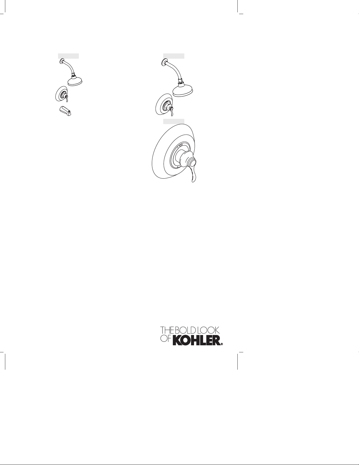
Installation Guide
Single-Control Bath and Shower Trim
K–12007 K–12014
K–12021
1031258-2-A
Page 2

IMPORTANT INSTRUCTIONS
READ AND SAVE FOR THE
CONSUMER
WARNING: Risk of scalding or other severe injury.
•
Before completing installation, the installer must set the
maximum water temperature setting of this valve to minimize the
risks associated with scalding hazards according to ASTM F 444.
•
Do not install a shut-off device on either outlet of this valve. The
installation of any such device may create a cross-flow condition
at the valve and affect the water temperature.
•
Factors that change the temperature of the water supplied to the
valve, such as seasonal water temperature changes, and water
heater replacement or servicing, will change the maximum water
temperature supplied by the valve and may create a scalding
hazard. The pressure-balanced valve will not compensate for
changes in the water supply temperature; adjust the maximum
water temperature setting of this pressure-balanced valve when
such changes occur.
•
Pressure-balanced valves may not provide protection against
scalding if there is a failure of other temperature-limiting devices
elsewhere in the plumbing system.
The installer is responsible for installing the valve and adjusting the
maximum water temperature of this pressure-balanced valve
according to instructions.
This valve meets or exceeds ANSI A112.18.1 and ASSE 1016.
If you do not understand any of the installation or temperature
adjustment instructions in this document, in the United States please
contact our Customer Service Department at 1-800-4-KOHLER.
Outside the U.S., please contact your distributor.
IMPORTANT NOTICE TO INSTALLERS! Please fill in the blanks in
the information box in the Homeowners Guide and on the valve label.
Retain the Homeowners Guide for future reference.
1031258-2-A 2 Kohler Co.
Page 3
NOTICE TO HOMEOWNERS! This device has been preset by
_______________________ of _______________________________ to
ensure a safe maximum temperature. Any change in the setting may
raise the discharge temperature above the limit considered safe, and
lead to scalds.
Date: ______________
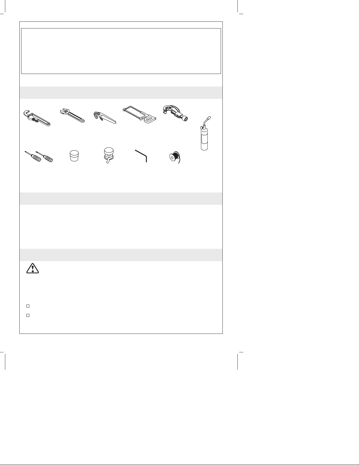
Tools and Materials
Pipe
Wrench
Assorted
Screwdrivers
Adjustable
Wrench
Plumbers
Putty
Strap
Wrench
Thread
Sealant
Hacksaw or Tubing Cutter
Propane
Torch
SolderHex
Wrench
Thank You For Choosing Kohler Company
We appreciate your commitment to Kohler quality. Please take a few
minutes to review this manual before you start installation. If you
encounter any installation or performance problems, please don’t
hesitate to contact us. Our phone numbers and web site are listed on
the back cover. Thanks again for choosing Kohler Company.
Before You Begin
CAUTION: Risk of product damage. The valve contains plastic
components. Do not apply excessive heat if you solder the valve
connections.
NOTE: To improve clarity, the plaster guard dome is not shown in
some of the illustrations.
Observe all local plumbing codes.
The valve shuts off by water pressure. Do not force the handle in
any direction. To turn the valve off, gently turn it to the ″Off″
position.
Kohler Co. 3 1031258-2-A
Page 4

Before You Begin (cont.)
Flush all piping thoroughly before installing this Rite-Temp valve.
Do not use plastic pipe between the Rite-Temp valve and the
spout. Use 1/2″ nominal copper tube or 1/2″ iron pipe.
Do not connect a deck-mount spout, diverter, or hand shower to
the spout outlet unless you cap the shower outlet on the valve.
Install a pipe or tube in a straight drop of 7” (17.8 cm) to 18″
(45.7 cm) with only one elbow between the valve and the
wall-mounted spout. Other types of installation may cause
unsatisfactory shower performance.
1031258-2-A 4 Kohler Co.
Page 5
72" (182.9 cm) –
78" (198.1 cm) to
Floor (Typical)
Bath/Shower
10"
(25.4 cm)
4" (10.2 cm)
Shower Installation
Installation
72" (182.9 cm) –
78" (198.1 cm)
to Floor (Typical)
48" (122 cm)
to Floor
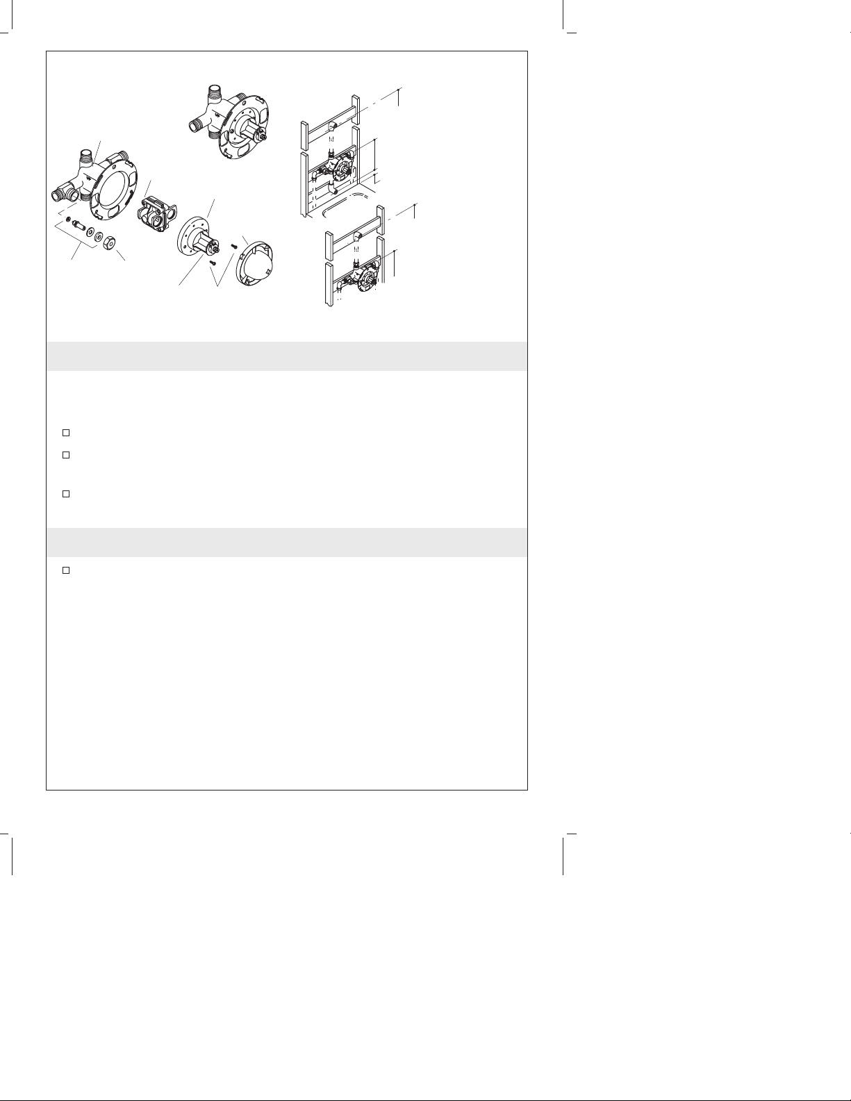
Valve
Body
Stem
Assembly
Pressure
Balancing Unit
Stop Nut
Valve
Cap
Less StopsWith Stops
Collar
Plaster
Guard
Screws
1. Prepare the Site
IMPORTANT! If the bath has been installed, cover it to prevent
damage to the bath surface.
Rough-in Plumbing
Shut off the main water supply.
Install or relocate the supplies as necessary.
Support Framing
Determine the location of the valve, and install the support
framing.
2. Prepare the Valve
Carefully remove the stop nut and stem assembly, valve cap,
collar, and pressure balancing unit before you apply soldering
heat to the valve body.
Kohler Co. 5 1031258-2-A
Page 6
Plaster
Guard
Cold Supply
Valve
Body
Hot Supply
Cap
Assembly
Collar
Tab
180˚
Screws
Shower Ell
1/2" Adapter or
Solder Direct
Hot Side
Bath Outlet
1/2" Copper
or Pipe
Shower Outlet
Cap
3. Shower Only Valve Installation
NOTE: A valve with stops is shown throughout the instruction.
Installations in the United States and Canada
Install the valve on the support framing so the “UP“ mark on the
valve is facing upward.
Installations in Mexico
Install the support framing so the “UP“ mark on the valve is
facing downward.
IMPORTANT! When reassembling the pressure balancing unit to
the valve body, make sure the seals in the pressure balancing unit
remain in position.
Rotate the cap assembly, pressure balancing unit, and collar 180°
(tab on bottom), reassemble, securely tighten the screws, and
reinstall the plaster guard.
All Installations
Install elbows and adapters (if needed) to 1/2″ copper tubing or
1/2″ pipe of proper length. Apply thread sealant, and connect the
piping to the shower outlet of the valve.
Cap the bath outlet with the cap provided.
1031258-2-A 6 Kohler Co.
Page 7

72" (182.9 cm) –
78" (198.1 cm) to
Floor (Typical)
10" (25.4 cm)
4" (10.2 cm)
Bath/Shower Installation
Shower Ell
1/2" Adapter or
Solder Direct
Hot Side
Bath Outlet
1/2" Adapter or
Solder Direct
1/2" Copper
or Pipe
Shower Outlet
1/2" Copper
or Pipe
Bath Ell
4. Bath and Shower Installations
NOTE: A valve with stops is shown throughout the instruction.
Install the valve on the support framing so the “UP“ mark on the
valve is facing upward.
Install elbows and adapters (if needed) to 1/2″ copper tubing or
1/2″ pipe of proper length. Apply thread sealant, and connect the
piping to the bath and shower outlets of the valve.
Kohler Co. 7 1031258-2-A
Page 8

1/2" Adapter or
Solder Direct
1/2" Copper
or Pipe
Temporary
Nipple
Valve Body
Cold Supply
Pressure
Balancing Unit
1/2"
Elbow
Hot
Supply
Stem
Assembly
Stop Nut
Temporary
Nipple
Collar
Screws
Valve Cap
5. Complete the Bath and Shower Installation
CAUTION: Risk of product damage. The valve body contains
plastic components. Remove the stop nut and stem assembly,
valve cap, and pressure balancing unit before you apply
soldering heat to the valve body.
For copper or iron supplies, connect the water supplies to the
valve body using elbows, 1/2″ copper tubing or pipe, and
adapters (if needed).
For PVC supplies, connect the water supplies to the valve body
using PVC elbows, 1/2″ PVC tubing, and PVC male adapters.
Use thread sealant on all threaded connections.
IMPORTANT! Secure the piping to the framing.
Temporarily install 1/2″ nipples to the bath and shower elbows.
They should extend at least 2″ (5 cm) beyond the finished wall.
If the inner valve components were removed for soldering,
carefully reinstall them now.
1031258-2-A 8 Kohler Co.
Page 9

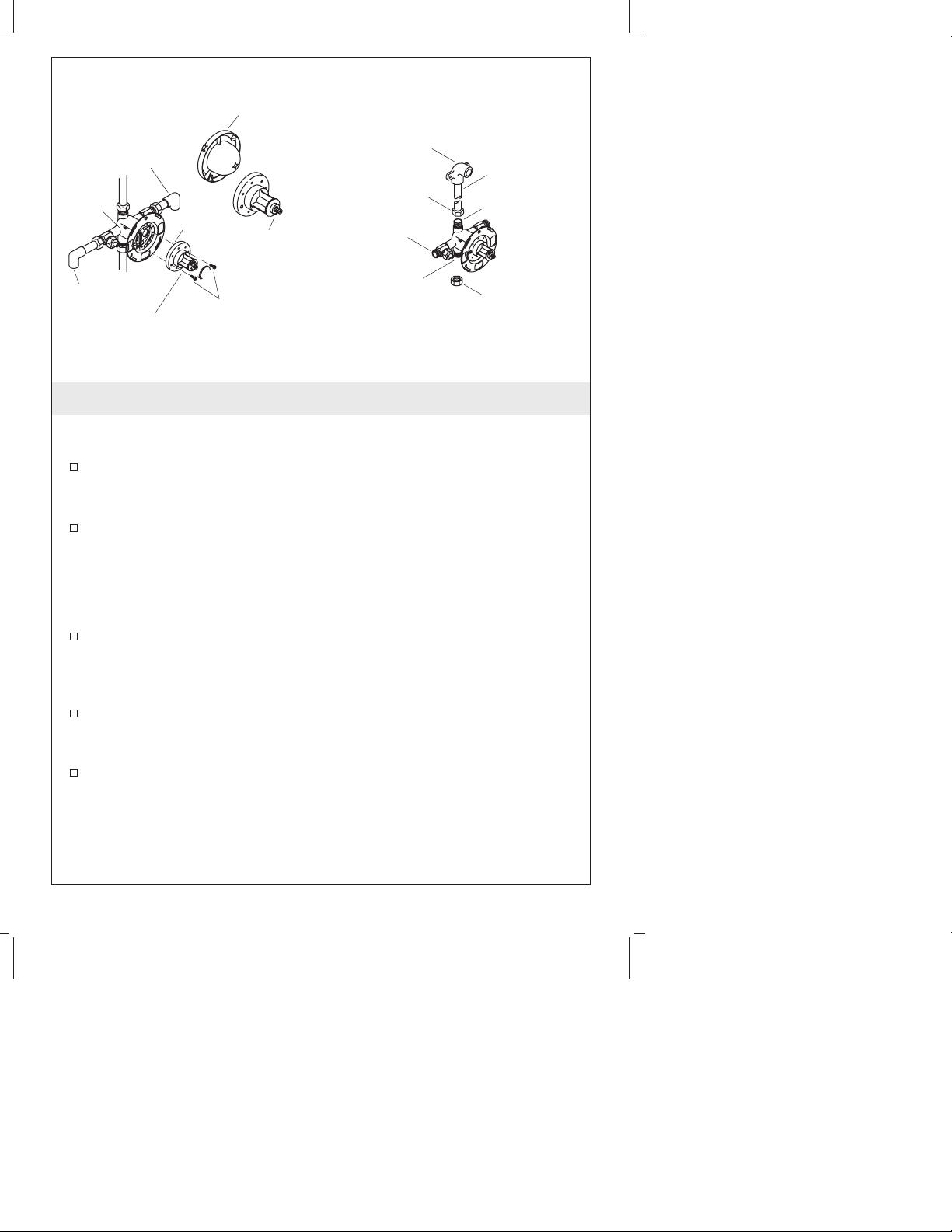
Plaster
Guard
Valve
Body
Cold Supply
Hot
Supply
Collar
Cap
Assembly
Tab
180˚
Screws
6. Back-to-Back Valve Installation
NOTE: Never install the valve body upside down.
Install both valves following the valve installation instructions.
The supplies to one of the valves will be reversed.
Remove the plaster guard, cap, cap assembly, and collar from the
valve with the reversed supply connections.
Rotate the cap assembly and collar 180° (tab on the bottom).
Reassemble, and securely tighten the screws.
Reinstall the plaster guard.
7. Installation Checkout
Install caps to the temporary bath and shower nipples.
Turn on the hot and cold water supplies, and check the new
installation for leaks.
Remove the caps from the temporary nipples.
Remove the plaster guard.
Turn the valve stem to the “On” position, and cycle the control
through its operating range. Check for leaks.
For bath and shower installations, check the diverter system from
spout to showerhead.
Turn the valve off.
Kohler Co. 9 1031258-2-A
Page 10

Installation Checkout (cont.)
If the valve has stops, rotate both stop adjustments fully
clockwise.
Turn the valve on, and verify that water does not run.
Turn the valve off, and rotate both stop adjustments fully
counterclockwise.
Reinstall the plaster guard.
1031258-2-A 10 Kohler Co.
Page 11

Finished Wall
5-9/16"
(14.1 cm) D.
Backing Plate
Outer Ring
Plaster Guard
Valve Stem
Dome
2-3/4" (7 cm) –
3-1/2" (8.9 cm)
Rough-In Depth
Thick Wall
Plaster Guard
Backing Plate
2-3/4" (7 cm)
Rough-In Depth
Wall Material
4" (10.2 cm) D.
Plaster Guard
Thin Wall
8. Finish the Wall
NOTE: Thick wall installations are typically tile, plaster, marble, or
similar materials. Thin wall installations are typically fiberglass and
acrylic.
Thick Wall Installations
Provide a 5-9/16″ (14.1 cm) diameter hole in the rough wall
material. The flat front surface of the plaster guard must be flush
with the finished wall.
Complete the finished wall.
Do not remove the plaster guard until instructed.
Thin Wall Installation
Remove the plaster guard from the backing plate.
Twist the plaster guard dome to separate it from the outer ring.
Discard the outer ring.
Slide the dome over the valve stem.
Provide a 4″ (10.2 cm) diameter hole in the finished wall material.
Make openings for the stops (if included) by using the holes in
the backing plate as a guide.
Secure the backing plate to the back of the wall material.
Do not remove the dome until instructed to do so.
Kohler Co. 1 1 1031258-2-A
Page 12

Slip-Fit Spouts
Copper Tube
Apply plumbers
putty.
Threaded Spouts
Nipple
1-1/2" (3.8 cm) –
2-7/8" (7.3 cm)
3-7/8"
(9.8 cm)
Apply plumbers
Setscrew
5/32" Hex Wrench
putty.
9. Install the Spout
CAUTION: Risk of internal seal damage. Do not use
petroleum-based lubricants when installing slip-fit spouts. If the
spout will not slide over the tubing, use soapy water or a
silicone-based lubricant.
CAUTION: Risk of internal seal damage. Loosen spout setscrew
with a 5/32″ hex wrench prior to installing the spout.
Slip Fit Spouts
Remove the temporary nipple from the bath elbow.
Apply thread sealant and install a 1/2” copper tube so it extends
1-1/2” (3.8 cm) to 2-7/8″ (7.3 cm) beyond the finished wall.
Deburr the copper tubing.
Loosen the setscrew with a 5/32″ hex wrench.
Apply a bead of plumbers putty or other sealant around the inlet
end of the spout according to the putty manufacturer’s
instructions.
Install the spout and carefully retighten the setscrew. Do not
overtighten the setscrew.
Remove all excess putty.
For Threaded Spouts
Remove the temporary nipple from the bath elbow.
1031258-2-A 12 Kohler Co.
Page 13

Install the Spout (cont.)
Apply thread sealant, and install a 1/2″ nipple so it extends
3-7/8″ (9.8 cm) beyond the finished wall.
Apply a ring of plumbers putty or other sealant to the back of the
spout according to the putty manufacturer’s instructions.
Apply thread sealant to the nipple, and install the spout to the
nipple. Carefully tighten with a clean strap wrench.
Remove excess putty.
Kohler Co. 13 1031258-2-A
Page 14

Shower
Elbow
Escutcheon
Shower Arm
Apply
plumbers
putty.
Setscrew
Showerhead
10. Install the Shower Arm and Showerhead
CAUTION: Risk of product damage. To avoid plugging the
showerhead spray outlets, use thread sealant tape on the shower
arm threads. Do not use thread sealant compound (pipe dope).
Remove the temporary nipple from the shower elbow.
Apply plumbers putty or other sealant to the back of the
escutcheon according to the putty manufacturer’s instructions.
Slide the escutcheon over the shower arm.
Apply thread sealant tape to the shower arm, and install the
shower arm to the shower elbow.
Carefully tighten with a clean strap wrench.
Press the escutcheon against the finished wall and secure with the
setscrew.
Remove all excess putty.
With the showerhead off, flush out the system.
Apply thread sealant tape to the shower arm and thread the
showerhead to the shower arm.
1031258-2-A 14 Kohler Co.
Page 15

Tab
Setscrew
Valve
Stem
Collar
Valve
Label
O-Ring
11. Water Temperature Adjustment
CAUTION: Risk of personal injury. The water temperature
should never be set above 120° F (49° C).
Turn the valve clockwise to the full open position and let the hot
water run for several minutes. Position a thermometer in the
water stream and check the temperature.
For minor water temperature changes, adjust the setscrew, and
recheck the water temperature.
For major water temperature changes, remove the O-ring and
collar from the valve stem. Slowly rotate the valve stem until the
desired water temperature is reached.
Reinstall the collar on the valve stem with the setscrew against
the side of the tab.
Reinstall the O-ring, rotate the valve stem counterclockwise to
shut the water off, and recheck the water temperature.
NOTE: After adjustment, complete the required information on the
valve label.
Kohler Co. 15 1031258-2-A
Page 16

Valve
Stem
Graphic Ring
Plaster Guard w/Dome
Discard
Face Plate
Screw
Insert
Sleeve
Handle
Screw
Washer
Plug
Button
12. Install the Face Plate
Remove and discard the plaster guard and/or dome, if installed
Install the face plate onto the valve. Secure with two screws. Do
not overtighten.
Install the graphic ring to the face plate, and rotate it clockwise to
lock it in place.
Rotate the valve stem fully counterclockwise.
Fit the sleeve onto the valve.
Align the handle, and press the handle and insert firmly onto the
valve stem.
Secure the handle with a washer and screw.
Press the plug button firmly into place, aligning the tab with the
notch in the handle.
13. Complete the Installation
Turn the valve fully counterclockwise to the off position.
Remove the aerator assembly from the spout by turning it
counterclockwise.
Turn on the main water supply.
Turn the valve to the center and run water for approximately one
minute to flush the system.
Check all connections for leaks.
Reinstall the aerator.
1031258-2-A 16 Kohler Co.
Page 17

1031258-2-A
Page 18

1031258-2-A
Page 19

1031258-2-A
Page 20

USA:1-800-4-KOHLER
kohler.com
©2004 Kohler Co.
1031258-2-A
 Loading...