

Page 1
{PeriodicPrevMaint}{Producti on} {HealthImaging}
Publication No. 7C8289
28JAN98
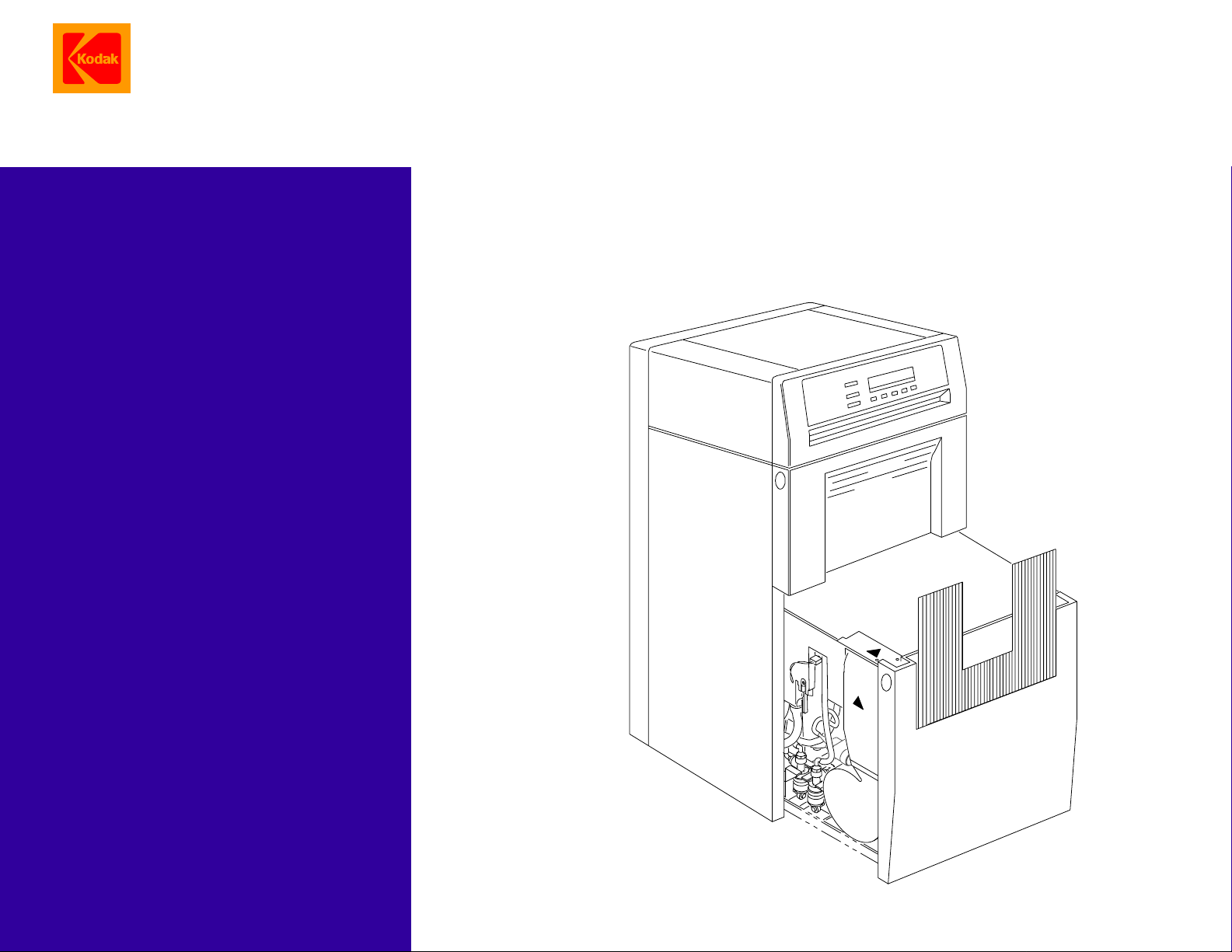
HEALTH IMAGING
PREVENTIVE MAINTENANCE
Kodak X-Omat
in a
Kodak X-Omat
for the
3000 RA INTEGRATED PROCESSOR
MULTILOADER 300 PLUS
© Eastman Kodak Company, 1999
Page 2

PLEASE NOTE The information contained herein is based on the experience and knowledge relating to the
subject matter gained by Eastman Kodak Company prior to publication.
No patent license is granted by this information.
Eastman Kodak Company reserves the right to change this information without notice, and
makes no warranty, express or implied, with respect to this information. Kodak shall not be liable
for any loss or damage, including consequential or special damages, resulting from any use of
this information, even if loss or damage is caused by Kodak’s negligence or other fault.
Table of Contents
Description Page
Weekly Preventive Maintenance . . . . . . . . . . . . . . . . . . . . . . . . . . . . . . . . . . . . . . . . . . . . 3
Monthly Preventive Maintenance . . . . . . . . . . . . . . . . . . . . . . . . . . . . . . . . . . . . . . . . . . . 5
3 Month Preventive Maintenance . . . . . . . . . . . . . . . . . . . . . . . . . . . . . . . . . . . . . . . . . . . 7
Preventive Maintenance Schedule . . . . . . . . . . . . . . . . . . . . . . . . . . . . . . . . . . . . . . . . . . 11
2 28JAN98 – 7C8289
Page 3
Weekly Preventive Maintenance
Section 1: Weekl y Preventive Maintenance
Important
The operator of the PROCESSOR should do the weekly preventive maintenance procedures in this section.
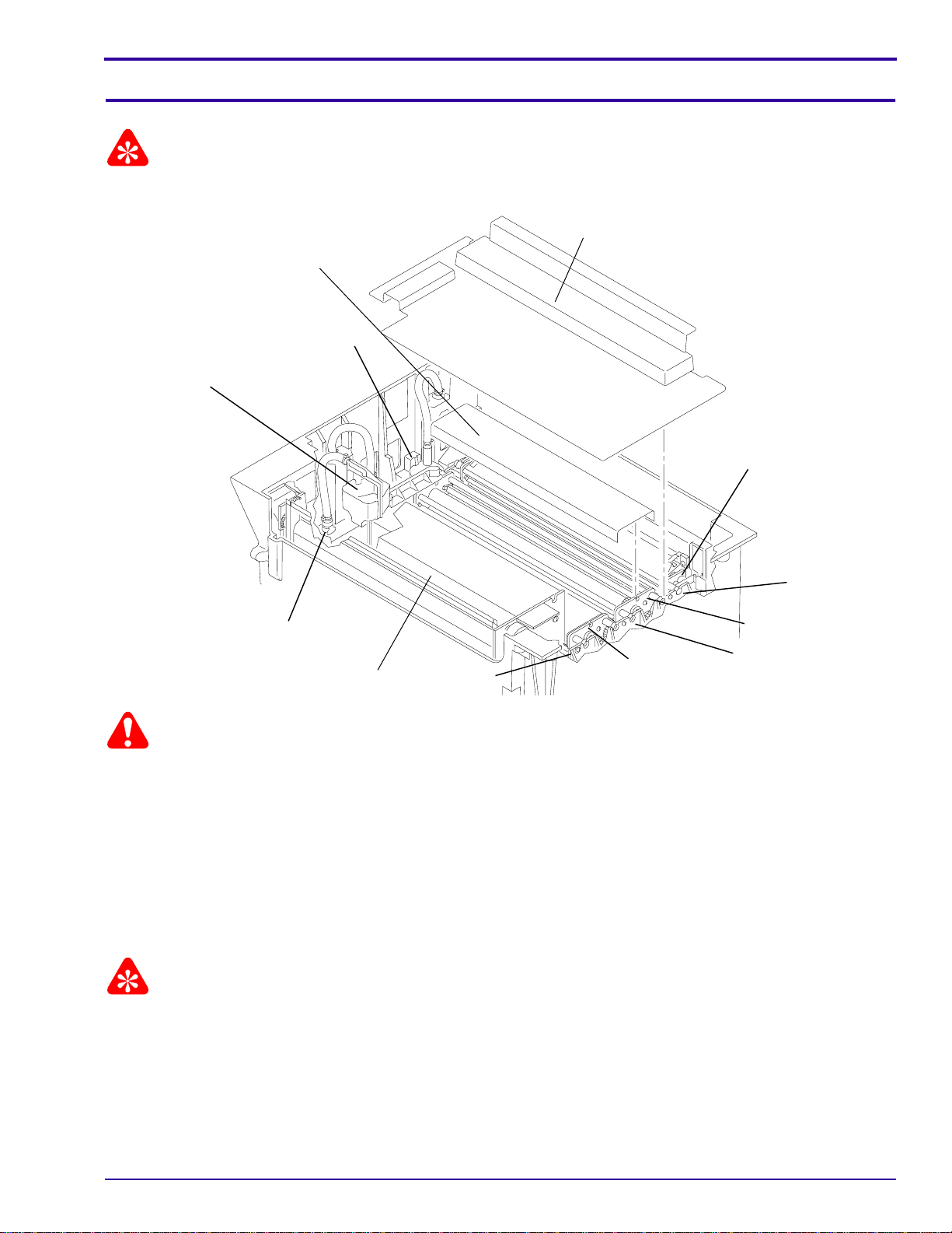
WET SECTION
COVER
ENTRANCE
CROSSOVER
WATER
RESERVOIR
2 EVAPORATION
COVERS
DEVELOPER
FILTER
DEVELOPER
RACK
DEVELOPER/FIXER
WATER DISCONNECT
H166_0003HCA
H166_0003HA
DRYER RACK
WASH
RACK
FIXER/
WASH
CROSSOVER
CROSSOVER
FIXER
RACK
Warning
Dangerous Voltage.
[1] De-energize the PROCESSOR.
[2] Remove the WET SECTION COVER.
[3] Disconnect the WATER RESERVOIR from the CROSSOVERS.
[4] Remove:
• EVAPORATION COVERS
• all CROSSOVERS
• WASH RACK
Important
Do not use abrasive cleaning materials on the ROLLERS.
[5] Rinse the 3 CROSSOVERS and the WASH RACK with warm water, 44C (110F) or less. Clean the ROLLERS
and the GUIDE SHOES with a damp, soft, synthetic sponge.
[6] Allow the ENTRANCE CROSSOVER to air dry before you install it in the PROCESSOR.
[7] Check that all the ROLLERS on all the CROSSOVERS and on the WASH RACK rotate freely.
[8] Check the squareness of the CROSSOVERS and the WASH RACK. See the procedures in the
ADJUSTMENTS AND REPLACEMENTS, Publication No. 7C8285.
7C8289 – 28JAN98 3
Page 4

PERIODIC PREVENTIVE MAINTENANCE
[9] Check that the CROSSOVER TROUGHS are clean, are not cracked or broken.
[10] Wipe any deposits from the processing section of the PROCESSOR.
[11] Install the following parts. Check that each assembly seats correctly:
• WASH RACK
• all CROSSOVERS
[12] Connect the WATER RESERVOIR to the CROSSOVERS.
[13] Check that the WATER DISCONNECT is positioned correctly.
[14] Install the following parts. Check that each assembly seats firmly:
• EVAPORATION COVERS
• WET SECTION COVER
[15] Engage the PROCESSOR in the MULTILOADER.
[16] Energize the PROCESSOR.
[17] Process a test film and check for correct operation of the PROCESSOR.
4 28JAN98 – 7C8289
Page 5

Monthly Preventive Maintenance
Section 2: Monthly Preventive Maintenance
Important
Completion of themonthly preventive maintenance procedures is recommended toensure the optimum reliability of
the PROCESSOR.
Warning
Dangerous Voltage.
[1] De-energize the PROCESSOR.
[2] Remove:
• WET SECTION COVER
• WATER DISCONNECT and WATER RESERVOIR
• EVAPORATION COVERS
• all CROSSOVERS
• DRYER RACK
• WASH RACK
Caution
To prevent contamination of the developer and fixer solutions when you remove the FIXER RACK and the
DEVELOPER RACK, placethe SPLASH GUARD between the DEVELOPER TANKand the FIXER TANK. Use the
DRIP TRAY when you remove or install the RACKS.
[3] Install the SPLASH GUARD between the DEVELOPER TANK and the FIXER TANK.
[4] Remove:
• DEVELOPER RACK
• FIXER RACK
• SPLASH GUARD
Important
Do not use abrasive cleaning materials on the ROLLERS.
[5] Rinse all the RACKS and the CROSSOVERS with warm water, 44C (110F) or less. Wipe the ROLLERS and
the GUIDE SHOES with a soft, synthetic sponge.
[6] Remove and clean the CROSSOVER TROUGHS. Check that the holes in the CROSSOVER TROUGHS are
free from biological growth or other obstructions.
[7] Install the CROSSOVER TROUGHS.
[8] On all RACKS, check:
(a) all ROLLERS rotate freely
(b) the ROLLERS are clean and smooth
(c) the GEARS do not have excessive wear
(d) the BEARINGS do not have excessive wear
(e) the SPROCKETS are engaged in the CHAINS
(f) the E-RINGS and SPRINGS are not broken, missing, or corroded
[9] If necessary, install new parts.
[10] Check the RACKS for squareness. See the procedures in the ADJUSTMENTS AND REPLACEMENTS,
Publication No. 7C8285.
7C8289 – 28JAN98 5
Page 6

PERIODIC PREVENTIVE MAINTENANCE
[11] Check that the SLOTS in the AIR TUBES are clean. If the parts are dirty:
(a) Remove the BAFFLES from the AIR TUBES.
(b) Rinse the BAFFLES with water.
(c) Clean the AIR TUBES with a BOTTLE BRUSH and rinse with water.
[12] Wipe any deposits from the processing section of the PROCESSOR.
[13] Change the DEVELOPER FILTER.
[14] Allow the ENTRANCE CROSSOVER to air dry before you install it in the PROCESSOR.
[15] Clean the WATER RESERVOIR.Checkthat the holes intheWATER RESERVOIRarefree of biological growth
and other obstructions.
[16] Install the RACKS.
[17] Install the following parts. Check that each part seats firmly.
• CROSSOVERS
• WATER RESERVOIR and WATER DISCONNECT
• EVAPORATION COVERS
• WET SECTION COVER
[18] Clean the REPLENISHMENT STRAINERS that are between the REPLENISHMENT TANKS and the
REPLENISHMENT PUMPS.
[19] Check the water supply FILTER. If necessary, change the FILTER.
Caution
• Any obstruction such as biological growth, tight bends, or an upward sloping WASH DRAIN HOSE can cause
wash water to return to the WASH TANK causing an overflow of water.
• Concentrationsofchlorinebleachhigherthan10%orallowingthechlorinebleach to remain in the PROCESSOR
for longer than 30 minutes can cause damage to the PROCESSOR.
[20] Check the WASH DRAIN for biological growth, tight bends, or other obstructions. To remove biological growth
do the following steps:
(a) Fill the WASH TANK and DRAIN with a 10% solution of chlorine bleach.
(b) Wait a minimum of 20 minutes and a maximum of 30 minutes.
(c) Drain the chlorine bleach solution and rinsethe TANK and DRAIN thoroughly with water before you return
the PROCESSOR to normal use.
Warning
• Drains at the site must be made of chemically resistant, non-corrosive material. Use PVC or the equivalent.
• The drain must have a minimum diameter of 7.6 cm (3.0 in.) and be free of obstruction.
• Drain service must comply with local codes.
[21] Correctly route the WASH DRAIN HOSE to slope down toward the floor DRAIN. If necessary, use
REINFORCED HOSES that resist making tight bends. Right angle ELBOW FITTINGS are also available. The
Part Numbers are:
• 696442 - Reinforced HOSE, 5/8-in. I.D. Order by the foot.
• 1C4521 - ELBOW FITTING, 5/8-in.
• 696441 - Reinforced HOSE, 1-in. I.D. Order by the foot.
• 1C4524 - ELBOW FITTING, 1-in.
[22] Energize the PROCESSOR.
[23] Process a test film and check for correct operation of the PROCESSOR.
6 28JAN98 – 7C8289
Page 7

3 Month Preventive Maintenance
Section 3: 3 Month Preventive Maintenance
Warning
Dangerous Voltage.
[1] De-energize the PROCESSOR.
[2] Open the FIXER and DEVELOPER DRAIN VALVES to drain the solutions from the PROCESSOR.
[3] Remove:
• WET SECTION COVER
• WATER DISCONNECT and WATER RESERVOIR
• EVAPORATION COVERS
• all CROSSOVERS
• DRYER RACK
• WASH RACK
Caution
To prevent contamination of the developer and fixer solutions when you remove the FIXER RACK and the
DEVELOPER RACK, place the SPLASH GUARD between the DEVELOPER TANK and the FIXER TANK. Use the
DRIP TRAY when you remove or install the RACKS.
[4] Install the SPLASH GUARD between the DEVELOPER TANK and the FIXER TANK.
[5] Remove:
• DEVELOPER RACK
• FIXER RACK
• SPLASH GUARD
Warning
• Carefullyfollowallsafety precautions and directions included with the
and
Kodak
DEVELOPER SYSTEM CLEANER AND NEUTRALIZER.
• The RACKS in the PROCESSOR have hollow ROLLERS. Use the instructions for cleaningRACKS with hollow
ROLLERS. Do not immerse RACKS with hollow ROLLERS in SYSTEM CLEANER. SYSTEM CLEANER that
remains inside the ROLLERS will contaminate the processing solutions.
• When circulating SYSTEM CLEANER or water through the recirculation system, energize the developer
COOLING SOLENOID and the RECIRCULATION PUMP using the PORTABLE COMPUTER. Otherwise the
following may occur:
– The effectiveness of the DEVELOPER SYSTEM CLEANER AND NEUTRALIZER will be greatly reduced
because of the developer remaining in the HEAT EXCHANGER.
– The DEVELOPER SYSTEM CLEANER AND NEUTRALIZER remaining in the HEAT EXCHANGER will
contaminate the new developer when the PROCESSOR is returned to operation.
[6] Clean the DEVELOPER RACK and the DEVELOPER TANK with
AND NEUTRALIZER, CATALOG No. 843 4615.
[7] Clean the FIXER RACK, the WASH RACK, and the FIXER TANK with
CLEANER, CATALOG No. 139 5110.
[8] Cleanthe WASHTANKwith
solution of chlorine bleach.
[9] If necessary, clean the LEVEL SENSOR PROBES with the correct SYSTEM CLEANER.
Kodak
FIXER/WASHSYSTEM CLEANERor, ifbiological growth exists,with a 10%
Kodak
Kodak
FIXER/WASHSYSTEMCLEANER
DEVELOPER SYSTEM CLEANER
Kodak
FIXER/WASH SYSTEM
7C8289 – 28JAN98 7
Page 8

PERIODIC PREVENTIVE MAINTENANCE
Important
Do not use abrasive cleaning materials on the ROLLERS.
[10] Rinse the following parts with warm water, 44C (110F) or less. Wipe the ROLLERS and the GUIDE SHOES
with a soft, synthetic sponge:
• CROSSOVERS
• EVAPORATION COVERS
• WET SECTION COVER
Note
If necessary, you may use DEVELOPER SYSTEM CLEANER AND NEUTRALIZER on the DEVELOPER/FIXER
CROSSOVER and FIXER/WASH SYSTEM CLEANER on the FIXER/WASH CROSSOVER.
[11] Remove and clean the CROSSOVER TROUGHS. Check that the holes in the CROSSOVER TROUGHS are
free from biological growth or other obstructions.
[12] Install the CROSSOVER TROUGHS.
[13] On all RACKS, check that:
(a) all ROLLERS rotate freely
(b) the ROLLERS are clean and smooth
(c) the GEARS do not have excessive wear
(d) the BEARINGS do not have excessive wear
(e) the SPROCKETS are engaged in the CHAINS
(f) the E-RINGS and SPRINGS are not broken, missing, or corroded
(g) the CHAIN is not worn or out of adjustment
[14] If necessary, install new parts.
[15] Check the RACKS for squareness. See the procedures in the ADJUSTMENTS AND REPLACEMENTS,
Publication No. 7C8285.
[16] Check that the SLOTS in the AIR TUBES are clean. If dirty:
(a) Remove the BAFFLES from the AIR TUBES.
(b) Rinse the BAFFLES with water.
(c) Clean the AIR TUBES with a BOTTLE BRUSH and rinse with water.
[17] Wipe any chemical deposits from the processing section of the PROCESSOR.
[18] Install a new DEVELOPER FILTER.
[19] Allow the ENTRANCE CROSSOVER to air dry before you install it in the PROCESSOR.
[20] Clean the WATER RESERVOIR.Check that theholes inthe WATER RESERVOIRare freeof biologicalgrowth
and other obstructions.
[21] Install the following parts. Check that each part seats firmly:
• RACKS
• CROSSOVERS
• WATER RESERVOIR and WATER DISCONNECT
• EVAPORATION COVERS
• WET SECTION COVER
[22] Clean the REPLENISHMENT STRAINERS located between the REPLENISHMENT TANKS and the
REPLENISHMENT PUMPS.
[23] Check the water supply FILTER. If necessary, change the FILTER.
8 28JAN98 – 7C8289
Page 9

3 Month Preventive Maintenance
Caution
• Any obstruction such as biological growth, tight bends, or an upward sloping WASH DRAIN HOSE can cause
wash water to return to the WASH TANK causing an overflow of water and damage to the ELECTRICAL BOX.
• Concentrationsof chlorine bleach higher than 10% or allowing the chlorinebleach to remain in the PROCESSOR
for longer than 30 minutes can cause damage to the PROCESSOR.
[24] Check the WASH DRAIN for biological growth, tight bends, or other obstructions. To remove biological growth
do:
(a) Fill the WASH TANK and DRAIN with a 10% solution of chlorine bleach.
(b) Wait a minimum of 20 minutes and a maximum of 30 minutes.
(c) Drain the chlorine bleachsolution, andrinse theTANK andDRAIN thoroughlywith waterbefore returning
the PROCESSOR to normal use.
Warning
• Drains at the site must be made of chemically resistant, non-corrosive material. Use PVC or the equivalent.
• The drain must have a minimum diameter of 7.6 cm (3.0 in.) and be free of obstruction.
• Drain service must comply with local codes.
[25] Correctly route the WASH DRAIN HOSE to slope down toward the WASH DRAIN. If necessary, use
REINFORCED HOSES that resist making tight bends. Right angle ELBOW FITTINGS are also available. The
Part Numbers are:
• 696442 - Reinforced HOSE, 5/8-in. I.D. Order by the foot.
• 1C4521 - ELBOW FITTING, 5/8-in.
• 696441 - Reinforced HOSE, 1-in. I.D. Order by the foot.
• 1C4524 - ELBOW FITTING, 1-in.
[26] Check the DRIVE CHAIN.
(a) If the DRIVE CHAIN is dry, apply lubricant to the DRIVE CHAIN. Use NLG1 - No. 2 LITHIUM BALL and
ROLLER BEARING GREASE TL-2324.
(b) If the DRIVE CHAIN is rusty, remove it and install a new DRIVE CHAIN.
(c) Adjust the tension of the DRIVE CHAIN. See the procedures in the ADJUSTMENTS AND
REPLACEMENTS, Publication No. 7C8285.
7C8289 – 28JAN98 9
Page 10

PERIODIC PREVENTIVE MAINTENANCE
SPRING
SPADE
H104_0383BCB
H104_0383BA
[27] Check the SPRING SPADES on the LEVELSENSOR PROBES for corrosion. If necessary, cleanor install new
SPRING SPADES.
[28] Close the DRAIN VALVES and fill the processing TANKS with processing solutions and starter where
necessary.
[29] Energize the PROCESSOR.
[30] Process a test film and check the PROCESSOR for correct operation.
[31] Check the negative pressure at the EXHAUST VENT for the DRYER. See the MULTILOADER 300 PLUS
INSTALLATION INSTRUCTIONS.
[32] Calibrate the REPLENISHMENT PUMPS. See the section “Calibrating the Replenishment System” in the
OPERATOR'S MANUAL for the
Kodak X-Omat
MULTILOADER 300 PLUS.
10 28JAN98 – 7C8289
Page 11

Preventive Maintenance Schedule
Section 4: Preventive Maintenance Schedule
Part or Assembly Weekly* Monthly** 3 Month Schedule***
ENTRANCE CROSSOVER C
DEVELOPER/FIXER CROSSOVER C
FIXER/WASH CROSSOVER C
WASH RACK C C(2)
DEVELOPER RACK I,C C(1)
FIXER RACK I,C C(2)
DRYER RACK I,C
RACK BEARINGS, CHAINS, and DRIVE GEARS I
Squareness of RACKS I
DRYER AIR TUBES I,C
DEVELOPER FILTER R
REPLENISHMENT STRAINERS and FILTERS C
Water Supply FILTER R
DRAIN HOSES I,R
Ventilation Exhaust T
DRIVE MOTOR CHAIN I,L
LEVEL SENSOR PROBES C
SPRING SPADES on the LEVEL SENSOR PROBES C(3)
DEVELOPER PROCESSOR TANK C(1)
FIXER and WASH PROCESSOR TANKS C(2)
Calibration of the REPLENISHMENT PUMPS T
WATER RESERVOIR C
I = Inspect for condition and adjust or install
new parts, if necessary.
L = Apply recommended lubricant.
R = Replace, if necessary.
T = Test and adjust, if necessary.
* The weekly preventive maintenance
procedures can be performed by the operator of
the PROCESSOR or by the trained service
provider.
** Completion of the monthly preventive
maintenance procedures is recommended to
ensure the optimum reliability of the
PROCESSOR.
Publication History
Print Date Pub. No. ECO No. Affected Pages File Name Notes
January 1998 7C8289 All pm3488_1_28jan98 First Printing
C = Rinse and clean carefully and completely
using warm water and a soft synthetic
sponge.
C(1) = Clean with
CLEANER AND NEUTRALIZER.
C(2) = Clean with
CLEANER.
C(3) = Clean any corrosion from the SPRING
SPADES.
*** The 3 month schedule is a guideline for sites
adhering to the site specifications issued by
Kodak. Actual usage and site characteristics may
require shorter intervals between maintenance.
Kodak
Kodak
DEVELOPER SYSTEM
FIXER/WASH SYSTEM
7C8289 – 28JAN98 11
Page 12

Printed in U.S.A. • pm3488_1.fm
EASTMAN KODAK COMPANY
Rochester, NY 14650
Kodak
and
X-Omat
are trademarks.
HEALTH IMAGING
 Loading...