

Page 1
supersedes SM 3058-5 from 12/97
SERVICE MANUAL
for the
Publication No. SM 3058-6
9/98
SM 3058-4 from 1/96
SM 3058-2 from 7/93
SM 3058 from 3/93
SM 3058 from 2/91
Kodak X-Omat
MULTILOADER 300 / 300 Plus
© KODAK AG STUTTGART, 1993, 1998
Page 2

PLEASE NOTE
The information contained herein is based on the experience and knowledge
relating to the subject matter gained by Kodak prior to publication.No patent license
is granted by this information.Kodak reserves the right to change this information
without notice, and makes no warranty, express or implied, with respect to this
information. Kodak shall not be liable for any loss or damage, including
consequential or special damages, resulting from the use of this information, even if
loss or damage is caused by Kodak’s negligence or other fault.
Page 3

SERVICEMANUAL SM3058-6
TABLEOFCONTENTS
ELECTROSTATICDISCHARGE.................................................................................................V
SAFETYWARNINGS......................................................................................VI
1.SPECIALTOOLS...................................................................................................................1-1
2.REPLACEMENTS..................................................................................................................2-1
INTRODUCTION...................................................................................................................2-1
CASSETTETRANSPORT....................................................................................................2-1
REPLACEMENTOFCASSETTEINPUTFLAPMOTOR.....................................................2-1
REPLACEMENTOFTHESHORTTRANSPORTROLLERS..............................................2-3
REPLACEMENTOFTHELONGTRANSPORTROLLER...................................................2-7
REPLACEMENTOFTHECASSETTEWIDTHTIMINGBELT.............................................2-9
REPLACEMENTOFTHECASSETTETRANSPORTMOTORM2...................................2-13
REPLACEMENTOFTHECASSETTEOPENERMOTORM5..........................................2-16
REPLACEMENTOFTHECASSETTEOPENERSOLENOIDY4......................................2-23
MAGAZINE OPENER.........................................................................................................2-26
REPLACEMENTOFTHEMAGAZINEOPENERMOTORM14.........................................2-26
FILM POCKET....................................................................................................................2-28
REPLACEMENTOFTHEFILMPOCKETSTEPPERMOTORM10..................................2-28
REPLACEMENTOFTHEFILMPOCKETSUCKERBARMOTORM15...........................2-30
REPLACEMENTOFFILMPOCKETTORSIONSPRING(SN<2000).............................2-32
REPLACEMENTOFFILMPOCKETTORSIONSPRING(SN>2000).............................2-35
REPLACEMENTOFTHEFILMPOCKETCLUTCHSPRING(SN>2000).......................2-37
REPLACEMENTOFTHE FILMREJECTERSPRING.......................................................2-40
PROCESSORINTERFACE................................................................................................2-42
REPLACEMENTOFPROCESSORINTERFACEMOTORM13.......................................2-42
PROCESSORINTERFACECLUTCHES............................................................................2-43
CONVEYOR.......................................................................................................................2-44
KodakAGStuttgart I 9/98
Page 4

SM 3058-6 SERVICE MANUAL
REMOVAL OF THE CONVEYOR ......................................................................................2-44
DISASSEMBLY OF THE CONVEYOR............................................................................... 2-47
REPLACEMENT OF THE FILM PICK UP MOTOR BELT (CARRIAGE)............................2-50
REPLACEMENT OF FILM PICK UP MOTOR (CARRIAGE) M6 ........................................ 2-51
REPLACEMENT OF CARRIAGE ASSEMBLY DRIVE BELTS...........................................2-52
REPLACEMENT OF SOLENOID CASSETTE SUCKER BAR TILTING Y7.......................2-54
REPLACEMENT OF THE SENSOR SUCKER BAR TILT B19........................................... 2-56
3. ADJUSTMENTS.....................................................................................................................3-1
INTRODUCTION...................................................................................................................3-1
SENSORS and DAYLIGHT................................................................................................... 3-1
FRAME LEVELLING .............................................................................................................3-2
CASSETTE AREA.................................................................................................................3-4
INPUT FLAP..........................................................................................................................3-4
CASSETTE REGISTRATION SENSOR B2..........................................................................3-5
CASSETTE OPENER GUIDE SHOE POSITION ................................................................. 3-7
CASSETTE OPENER MECHANISM.................................................................................... 3-8
CASSETTE BLOW PIPE HOLDER.....................................................................................3-12
CASSETTE BLOW PIPE POSITION .................................................................................. 3-13
CASSETTE SUCKER BAR.................................................................................................3-14
CASSETTE TYPE 2 SENSORS. (B21 and B22)................................................................3-22
CASSETTE LENGTH .........................................................................................................3-25
SENSOR B20 VACUUM OFF ............................................................................................3-27
DRIVE BELT TENSION ......................................................................................................3-34
FILM POCKET ...................................................................................................................3-35
HOW TO CLEAN THE SUCKERS...................................................................................... 3-35
FILM POCKET CHAIN ........................................................................................................3-35
FILM POCKET ADJUSTMENT ........................................................................................... 3-39
MAGAZINE EMPTY SENSOR............................................................................................3-60
9/98 II Kodak AG Stuttgart
Page 5

SERVICE MANUAL SM 3058-6
DOUBLE SHEET SENSOR SN < 3000 .............................................................................. 3-62
DOUBLE SHEET SENSOR SN > 3000 .............................................................................. 3-63
MAGAZINE LEVELS...........................................................................................................3-69
NEARLY EMPTY ADJUSTMENT ....................................................................................... 3-71
SCAN RUN.......................................................................................................................... 3-72
MAGAZINE AREA............................................................................................................... 3-73
MAGAZINE OPENER ......................................................................................................... 3-73
STEPPER MOTOR FILM POCKET M10/M_PO.................................................................3-75
FILM CHUTE ...................................................................................................................... 3-78
INTERFACE FLAP ............................................................................................................ 3-78
INTERFACE FLAP CAM and SENSOR B33 ...................................................................... 3-79
FILM RELEASE .................................................................................................................. 3-82
FILM CHUTE GUIDE ..........................................................................................................3-85
STEPPER MOTOR PROCESSOR INTERFACE M13/M_PI ..............................................3-86
SENSOR B35 FILM IN INTERFACE BOTTOM ..................................................................3-88
ADJUSTMENT SENSOR B25 / B26 ML300 Plus...............................................................3-92
ADJUSTMENT SENSOR B24............................................................................................. 3-94
ADJUSTMENT PCB A10 .................................................................................................... 3-96
4. PARAMETER......................................................................................................................... 4-1
INTRODUCTION...................................................................................................................4-1
HOW TO SET A PARAMETER............................................................................................. 4-1
CASSETTE UNIT..................................................................................................................4-2
VACUUM OFF TIME.............................................................................................................4-2
BLOW TIME .......................................................................................................................... 4-3
CASSETTE OFFSET ............................................................................................................4-3
DISABLE OPENER............................................................................................................... 4-4
CASSETTE OPEN / RETURN.............................................................................................. 4-5
DISABLE INTERFACE..........................................................................................................4-5
Kodak AG Stuttgart III 9/98
Page 6

SM 3058-6 SERVICE MANUAL
MAGAZINE UNIT ..................................................................................................................4-6
TILT POSITION.....................................................................................................................4-6
ADDITIONAL STEPS............................................................................................................ 4-7
LOWER POCKET .................................................................................................................4-7
MAGAZINE LEVELS............................................................................................................. 4-8
NEARLY EMPTY................................................................................................................... 4-9
DOUBLE FILM DETECTION................................................................................................. 4-9
CONVERSION TABLES ..................................................................................................... 4-10
5. RESIZING MAGAZINES ....................................................................................................... 5-1
6. X-OMATIC CASSETTES .......................................................................................................6-1
LATCH ADJUSTMENTS.......................................................................................................6-1
TYPE2 CODING OF CASSETTES.......................................................................................6-1
7. Changes for XML300 with SN > 2000..................................................................................7-1
CASSETTE OPENER ........................................................................................................... 7-1
FILM TYPE 2 SENSOR MOUNT .......................................................................................... 7-4
NEW CASSETTE TRANSPORT ROLLERS.........................................................................7-5
NEW FILM PICK UP MOTOR M6.........................................................................................7-6
IMPROVED FILM POCKET .................................................................................................. 7-7
NEW PROCESSOR INTERFACE.......................................................................................7-12
MOUNTING BRACKET INTERFACE FLAP MOTOR M11................................................. 7-13
MAGAZINE HOLDERS ....................................................................................................... 7-13
MAGAZINE DOOR PIVOTS................................................................................................7-14
SOFTWARE VERSION 3.23 and above.............................................................................7-15
DFF FEATURES .................................................................................................................7-15
SERVICE CALLS................................................................................................................7-17
NEW CASSETTE OPENER SEQUENCE .......................................................................... 7-18
PARAMETERS AND SOFTWARE UPDATE......................................................................7-18
8. Changes for XML300 with SN > 3000..................................................................................8-1
9/98 IV Kodak AG Stuttgart
Page 7

SERVICE MANUAL SM 3058-6
OPERATING SOFTWARE version 3.31. .............................................................................. 8-1
HARDWARE CHANGES.......................................................................................................8-3
9. Changes for XML300 Plus.................................................................................................... 9-1
10. PREVENTIVE MAINTENANCE ......................................................................................... 10-1
Preparation:......................................................................................................................... 10-1
General Activities:................................................................................................................10-1
CASSETTE AREA:..............................................................................................................10-3
AIR FILTER.........................................................................................................................10-5
HUMIDIFIER (MOD 14)....................................................................................................... 10-6
HUMIDIFIER (MOD 42)....................................................................................................... 10-7
VENTING ............................................................................................................................10-8
FINAL CHECK-OUT:.........................................................................................................10-10
11. COMPONENT LOCATOR ................................................................................................. 11-1
CONNECTORS................................................................................................................... 11-1
MOTORS............................................................................................................................. 11-1
PRINTED CIRCUIT BOARDS.............................................................................................11-1
SENSORS .......................................................................................................................... 11-2
SOLENOID VALVES...........................................................................................................11-3
SOLENOIDS ...................................................................................................................... 11-3
SWITCHES .........................................................................................................................11-3
POWER SUPPLY................................................................................................................ 11-3
Kodak AG Stuttgart V 9/98
Page 8

SM 3058-6 SERVICE MANUAL
9/98 VI Kodak AG Stuttgart
Page 9

ESD SM 3058-6
ELECTROSTATIC DISCHARGE
OVERVIEW
ESD—electrostatic discharge—is a primary source of:
· product downtime
· lost productivity
· costly repairs.
While we cannot even feel a static charge of less than 3,500 volts, a s few as 30 volts can
damage or destroy essential components in t he electronic eq uipment upon which you rely. As
technology continues to advance, these advanced components will be even more vulnerable
to ESD destruction. The conclusion is clear. To tak e charge of p roductivity and p rofitability,
you must take care of ESD, now. Effective ESD control requires the following things.
AWARENESS
Everyone in your organisa tion needs to b e aware of ESD , because p artial ESD control is no
ESD control at all. Ev eryone needs to remember that:
· ESD is a primary source of frustrating equipment failures and intermittent malfunc tions.
ESD affects productivity and profitability.
ESD can be co ntrolled.
ACTION
To take charge of ESD , you must take action. And that mean s everyone from senior
management to the evening security crew.
If you repair and maintain electronic equipment, it means always w earing grounding straps
and working at ESD- protected sites.
If you ever work around electronic eq uipment, it means keeping static gener ators like plas tic
trash bags away from sensitive components.
For everyone, taking charge of ESD means maling the simple ESD controls a way of life.
(See the following sec tions for sp ecial tips).
EFFECTIVE ESD CONTROL IS EVERYONE’S RESPONSIBILITY.
EVERY DAY
1. Put trash in its place. A nd that place is away from static-sensitive equipment. Plastic
materials, like trashcan liners and plastic foam cups, generate t he static elec tricity that
damages or destroys e lectronic components .
2. Look for the label. Static-sensitive components are marked with bright graphic labels. Look
for these labels. Follow label directions.
3. Sp ray the carpe t. ESD that is generated when yo u walk over ca rpet is a ma jor culprit in
component destruction. In some cases, especially in low-humidity environments, you may
need to periodically spray carpets with an anti-static preparation, available at loca l stores.
KODAK AG, Stuttgart V 9/98
Page 10

SM 3058-6 ESD
DURING MAINTENANCE AND REPAIR
· Wear a grounding strap when you deal with static -sensitive components . Always mak e
certain that the clip is attached to a properly grounded, unpainted surface.
· Use a portable grounding mat if you cannot r epair components at an ESD-protected
workstation. (Kodak’s Customer Equipment Services Division can assist you in setting up
ESD-protected workstations .)
· Use protective pack aging when y ou transport components from one area to another.
Transparent anti static bags , available from a variety of manufactures , shield your
just-repaired components from further damage.
SAFETY WARNINGS
· BE CAREFUL WHEN WORKING IN THE CASSETTE OPENER AREA. THE OPENER
MOTOR AND THE OPENER MECHANISM ARE VERY STRONG. THEY CANNOT BE
MOVED MANUALLY. THEY MAY SQUEEZE YOUR HAND AND TRAP YOU IF YOU TRY
TO STOP THEM MANUALLY. NEVER START THE CASSETTE OPENER MOTOR WHEN
SOMEONE’S HANDS ARE IN THE CASSETTE AREA.
· DISCONNECT THE POWER WHEN TAKING OUT OR INSTALLING THE POWER
SUPPLY. IT IS POSSIBLE TO TOUCH THE MAINS VOLTAGE.
· IF YOU TAKE OUT SAFETY COVERS OR WIRE TIES TO HAVE EASIER ACCESS TO
PARTS, INSTALL THEM B EFORE YOU MOUNT THE SIDE PANELS WHEN THE
SERVICE CALL OR THE PM IS FINISHED.
· BE CAREFUL WHEN WORKING ON CIRCUIT BOARDS A4 AND A8. THERE ARE 120
VAC ON THOSE BOARDS. BE ESPECIALLY CARE FUL WHEN MEASURING ON THE
REAR SIDE OF THE CIRCUIT BOARDS OR WHE N A4 IS PIVOTED OUT OR A8 IS
PIVOTED UP. AN ELECTRIC SHOCK MAY RESULT.
· WHEN WORKING IN THE AREA OF PCB A4, COVER THE VENTING HOLE AT THE
TOP OF THE POWER SUPPLY SO THAT NOTHING MAY FALL INTO IT. TAKE THIS
COVER OFF BEFORE MOUNTING THE SIDE PANELS TO AVOID OVERHEATING OF
THE SYSTEM.
9/98 VI KODAK AG, Stuttgart
Page 11

TOOLS SM 3058-6
1. SPECIAL TOOLS
VERNIER CALIPER ......................................................................................................TL 1727
GREASE...........................................................................................................................TL 2247
TEMPLATE CASSETTE TYPE 2 ................................................................................9194501
METRIC ALLEN SET.....................................................................................................TL 2764
METRIC ALLEN SET BALL ENDED...........................................................................TL 3789
METRIC OPEN END WRENCH SET ..........................................................................TL 2765
METRIC OPEN END WRENCH 5.5mm......................................................................TL 1936
ESD KIT ...........................................................................................................................TL 3346
DENTIST MIRROR.........................................................................................................TL 2753
LOGIC PEN.....................................................................................................................TL 3008
EXTRACTION TOOL ......................................................................................................TL 1580
EXTRACTION TOOL ......................................................................................................TL 1654
THICKNESS GAUGE .....................................................................................................TL 2372
LAPTOP DATA CABLE .................................................................................................TL 4391
TORX WRENCH SET ....................................................................................................TL 3261
BLOW PIPE POSITIONER CASSETTE ......................................................................TL 4830
BLOW PIPE POSITIONER MAGAZINE......................................................................TL 4582
CES SERVICE SOFTWARE..............................................................G9904537 / TL4462 ***
LAPTOP COMPUTER, has to be bought locally.
*** Always use the lates t software vers ion available.
KODAK AG, Stuttgart 1-1 9/98
Page 12

SM 3058-6 TOOLS
9/98 1-2 KODAK AG, Stuttgart
Page 13
REPLACEMENTS SM 3058-6
2. REPLACEMENTS
INTRODUCTION
In this section it is very often explained how to use the CES SERVICE SOFTWARE. The first
line tells always what should be performed. In the next lines it is explained how to reach this
goal. These additional explanations are printed italic and can be skipped if you are
experienced w ith the CES SERVICE SOFTW ARE.
EXAMPLE:
1. Start the CASSETTE INPUT FLAP MOTOR M1
Start the SERVICE PROGRAM.
Select SERVICE MODE from the GLOBAL MENU....................................... press ENTER
ENTER SERVICE MODE MESSAGE is displayed............................................press ENTER
UNIT DATA are displayed ...............................................................................press ENTER
Select COMPONENT TEST from the MAIN MENU.......................................press ENTER
Select CASSETTE MOTORS ...............................................................................press ENTER
Select INPUT FLAP MOT M1.............................................................................press ENTER
Select CLOSE/OPEN.......................................................................................... press ENTER
CASSETTE TRANSPORT
REPLACEMENT OF CASSETTE INPUT FLAP MOTOR.
1. Switch off the ML300.
2. Take off the PANELS.
3. Take off the MOTOR CAM.
MOUNTING SCREW (4)
MOUNTING SCREW (4)
GUIDE BRACKET
NUT
CAM
figure 2-1
KODAK AG, Stuttgart 2-1 9/98
Page 14

SM 3058-6 REPLACEMENTS
4. Take out the 2 MOUNTING SCREWS of the GUIDE BRACKET.
5. Remove the NUT.
6. Take off the GUIDE BRACKET.
7. Take off the INPUT FLAP.
8. Take out the 4 MOUNTING SCREWS of the MOTOR INPUT FLAP.
9. Install the new MOTOR.
FUNCTION TEST
1. Start the CASSETTE INPUT FLAP MOTOR M1
Start the SERVICE PROGRAM.
Select SERVICE MODE from the GLOBAL MENU....................................... press ENTER
ENTER SERVICE MODE MESSAGE is displayed............................................press ENTER
UNIT DATA are displayed ...............................................................................press ENTER
Select COMPONENT TEST from the MAIN MENU.......................................press ENTER
Select CASSETTE MOTORS ...............................................................................press ENTER
Select INPUT FLAP MOT M1.............................................................................press ENTER
Select CLOSE/OPEN.......................................................................................... press ENTER
2. Make sure that the MOTOR CAM turns clockwise. If it turns counter-clockwise
interchange PIN 1 and 3 at the MOTOR C ONNECTOR.
3. Exit the SERVICE PROGRAM
Press 3 times BACKSPACE.
Select LEAVE COMPONENT TEST ...................................................................press ENTER
Select QUIT ML300 SERVICE MODE............................................................... press ENTER
Select Quit the program................................................................................. press ENTER
9/98 2-2 KODAK AG, Stuttgart
Page 15
REPLACEMENTS SM 3058-6
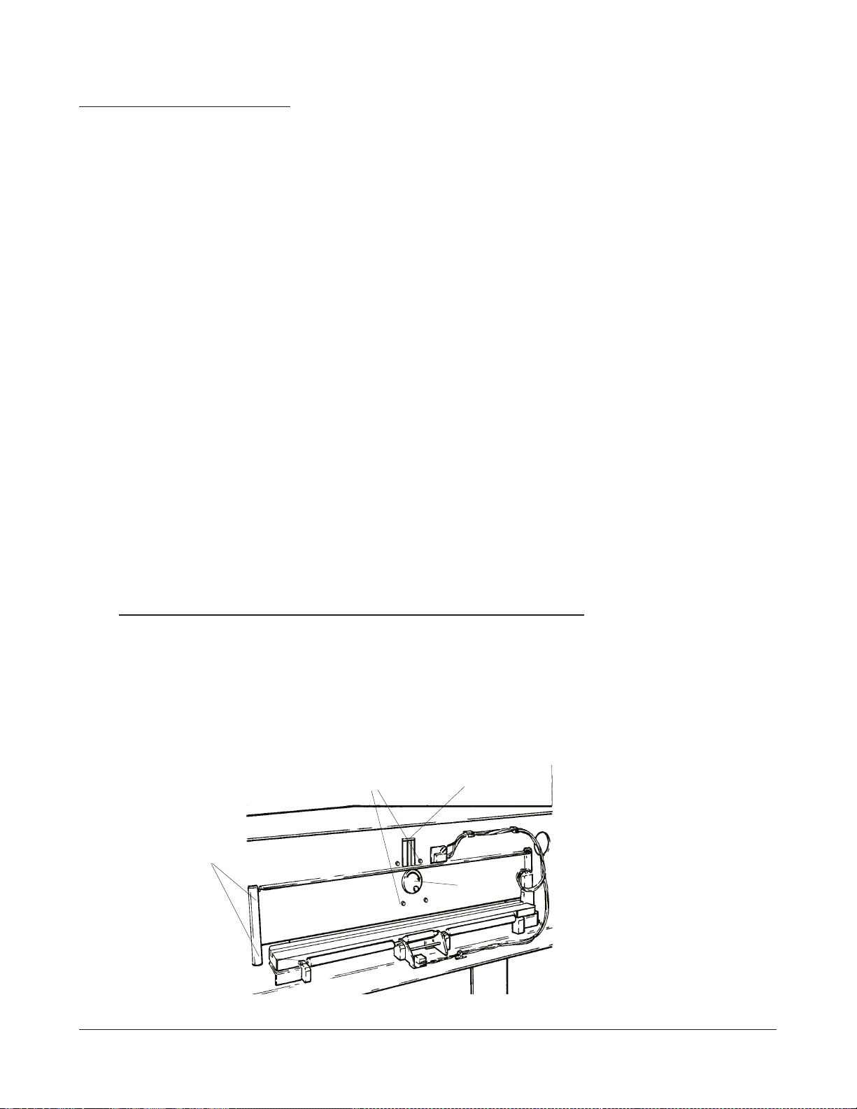
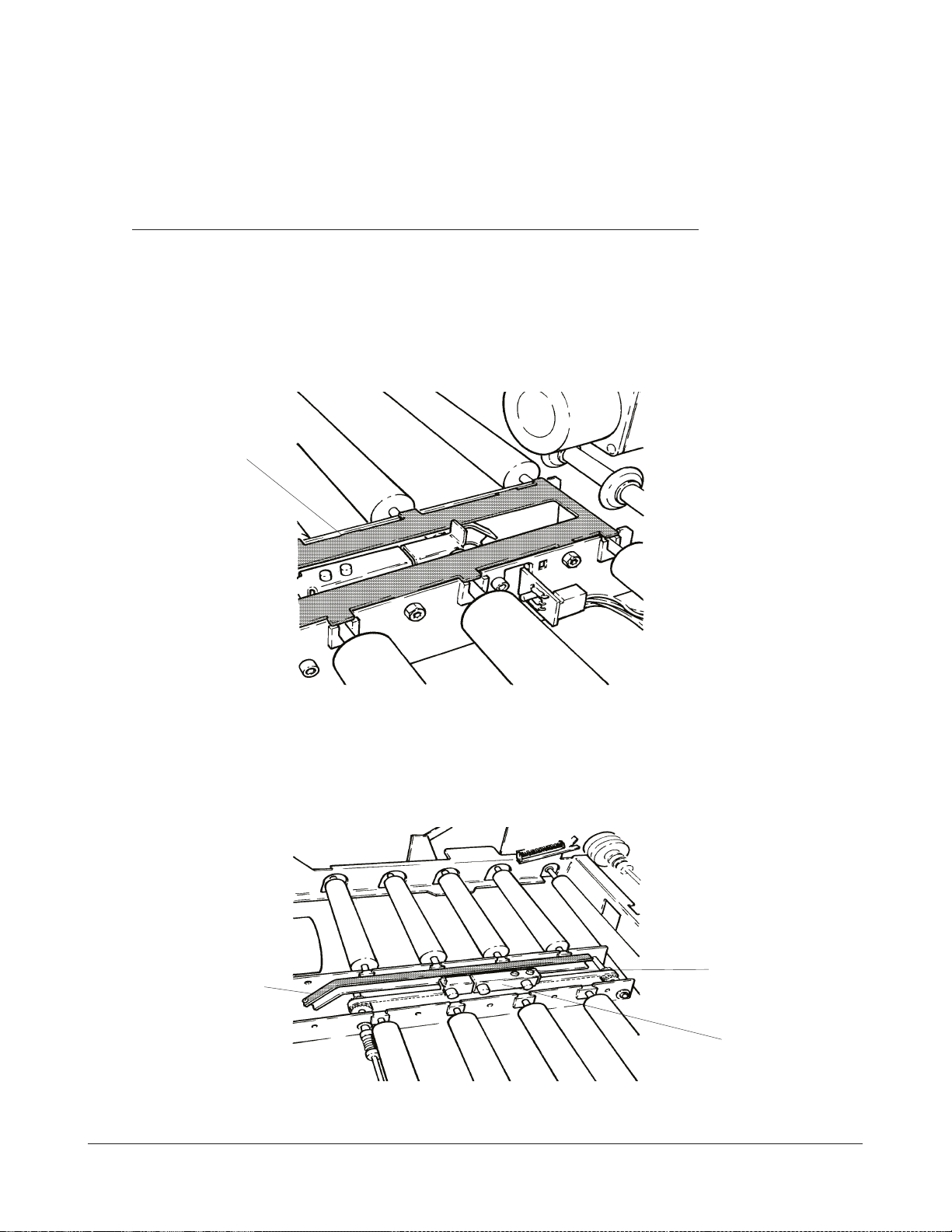
REPLACEMENT OF THE SHORT TRANSPORT ROLLERS.
1. Switch off ML300.
2. Take off the PANELS.
3. Remove the COVE R PLATE .
REAR
COVER PLATE
MOTOR INPUT FLAP
FRONT
MOUNTING SCREW (6)
figure 2-2
KODAK AG, Stuttgart 2-3 9/98
Page 16
SM 3058-6 REPLACEMENTS
Note
There is a SPACER between the 2 BALL B EARINGS of the BELT TENS IONER.
4. Remove the FRONT BELT TENSIONER and take off the DRIVE BELT.
BELT
TENSIONER
SPACER
BALL
BEARING
figure 2-3
9/98 2-4 KODAK AG, Stuttgart
Page 17
REPLACEMENTS SM 3058-6
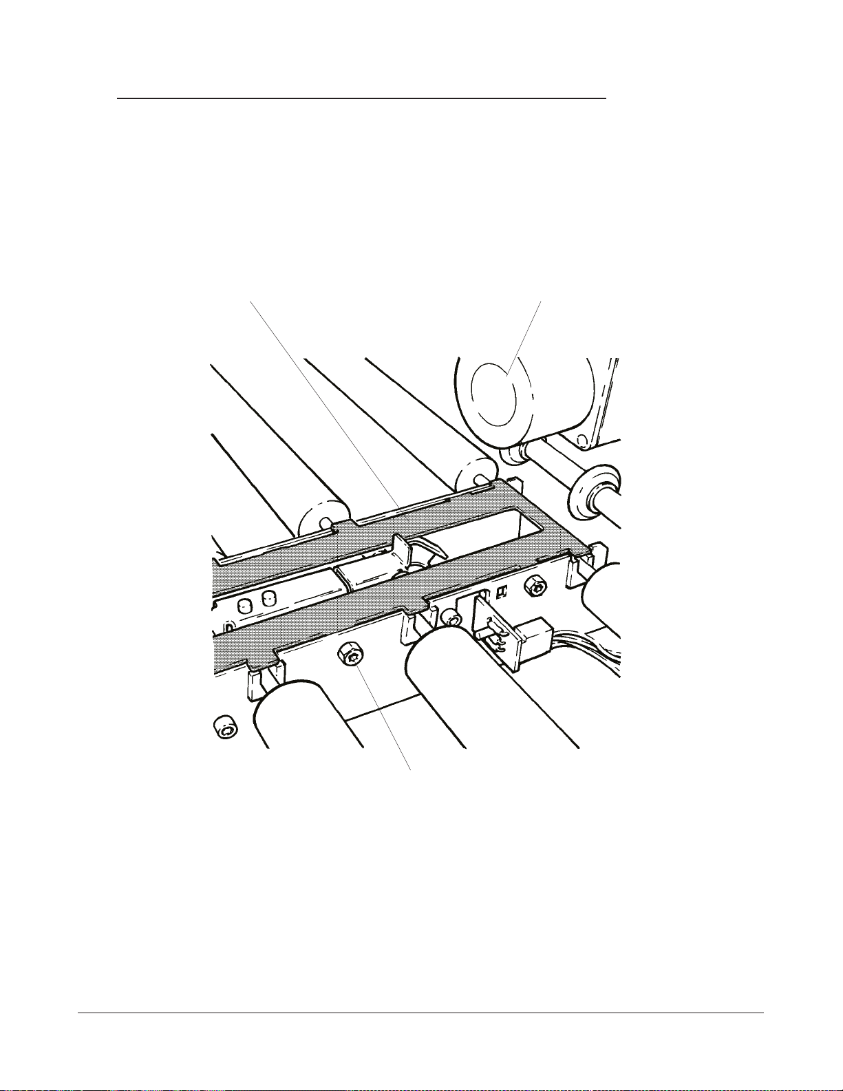
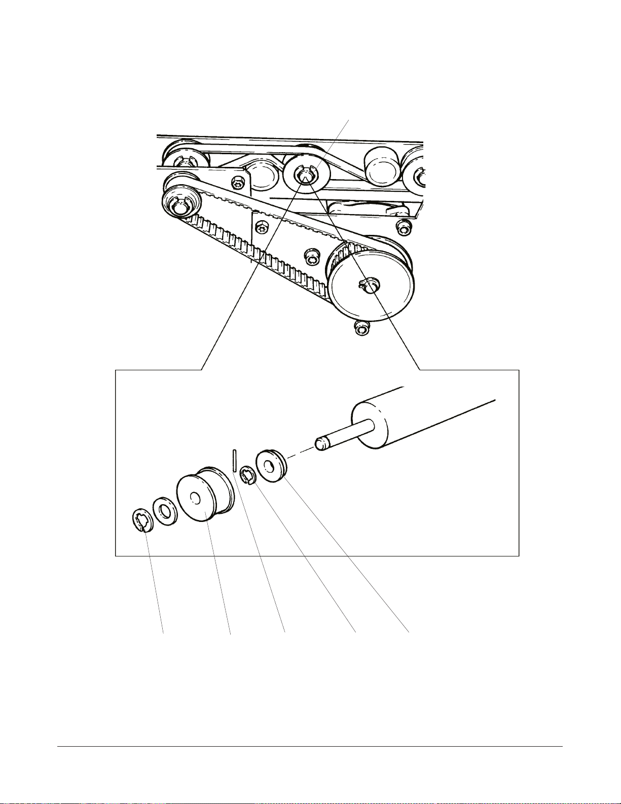
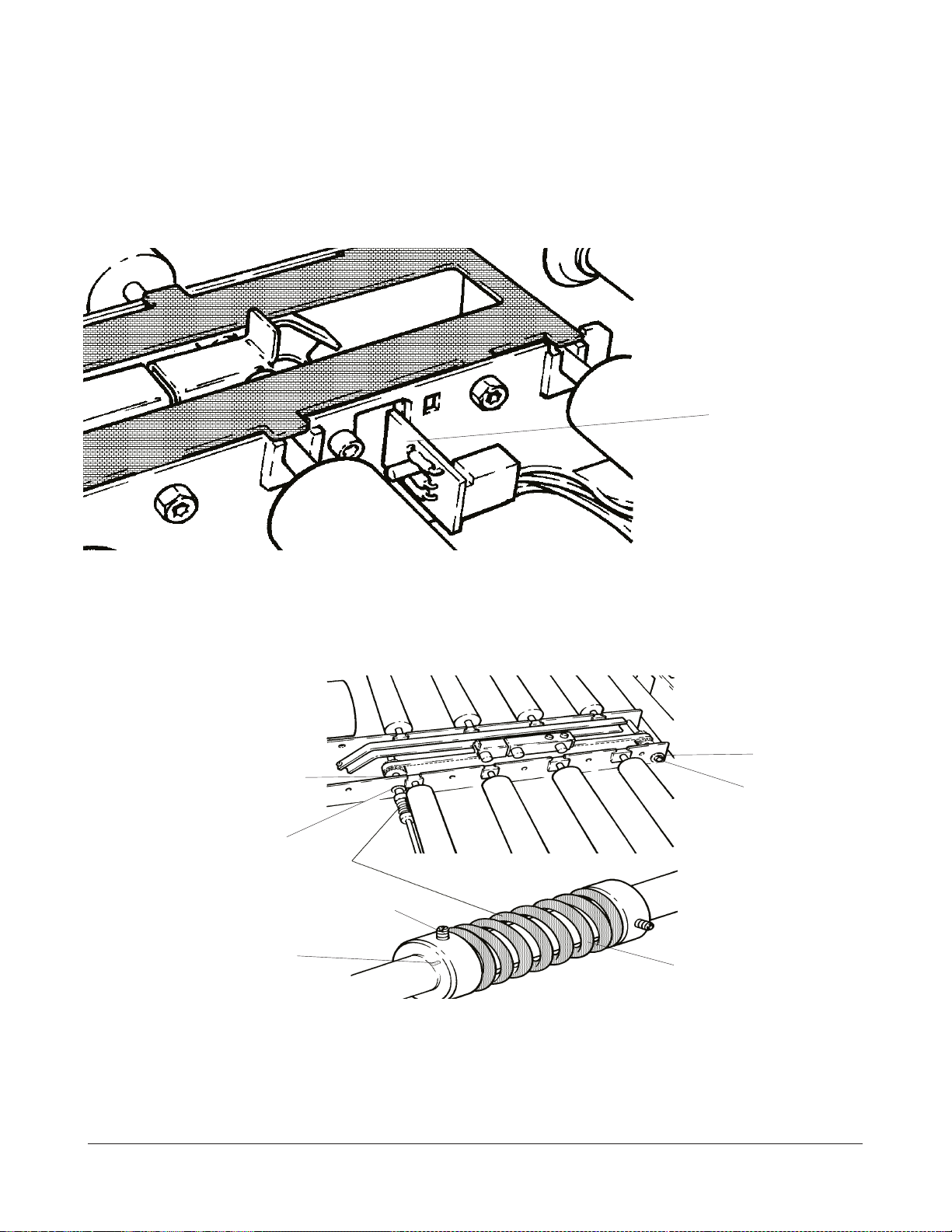
5. Take off the C-RING at the DRIVE PULLEY.
C-RING
C-RING DRIVE PULLEY DOWEL PIN C-RING BALL BEARING
figure 2-4
KODAK AG, Stuttgart 2-5 9/98
Page 18
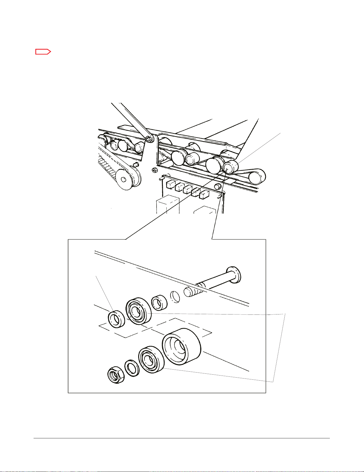
SM 3058-6 REPLACEMENTS
6. Take out the DRIVE PU LLEY with the DOW EL PIN.
7. Take off the C-RING of the BALL BEARING.
8. Take off the BALL BEARING.
9. Lift the ROLLER END with the PLASTIC BEARING and pull out the TRANSPORT
ROLLER.
Note
Make sure that all PLASTIC BEARINGS are installed as shown in the figure below.
10. Install the new TRANS PORT ROLLER.
This side of all PLASTIC BEAR-
INGS must show up
figure 2-5
FUNCTION TEST
1. Check that a CASSETTE is transported correctly forward and backward.
9/98 2-6 KODAK AG, Stuttgart
Page 19
REPLACEMENTS SM 3058-6
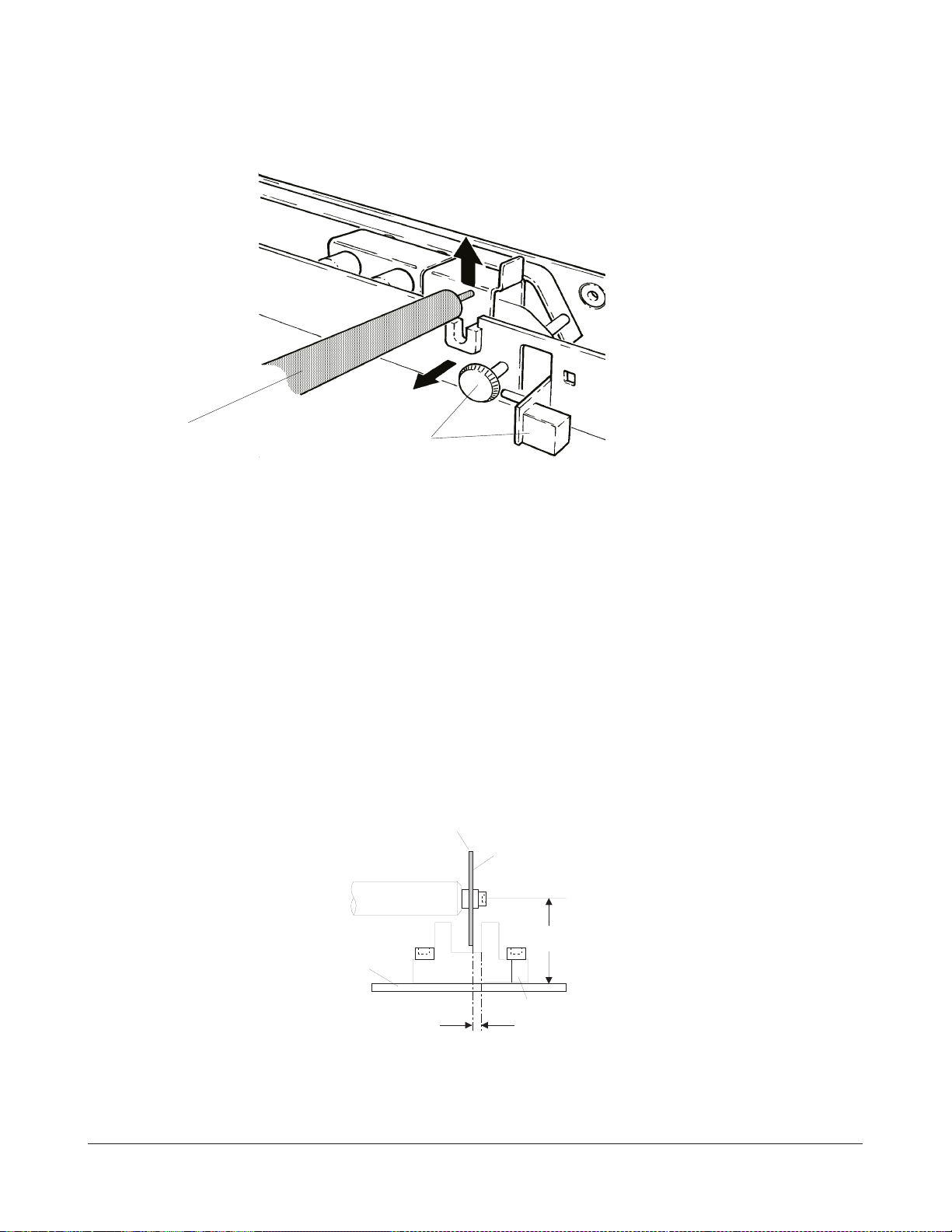
REPLACEMENT OF THE LONG TRANSPORT ROLLER.
1. Switch off the ML300.
2. Take off the PANELS.
3. Remove the COVER PLATE of the HOLDING FINGER ASSEMBLY.
COVER PLATE
REAR
figure 2-6
FRONT
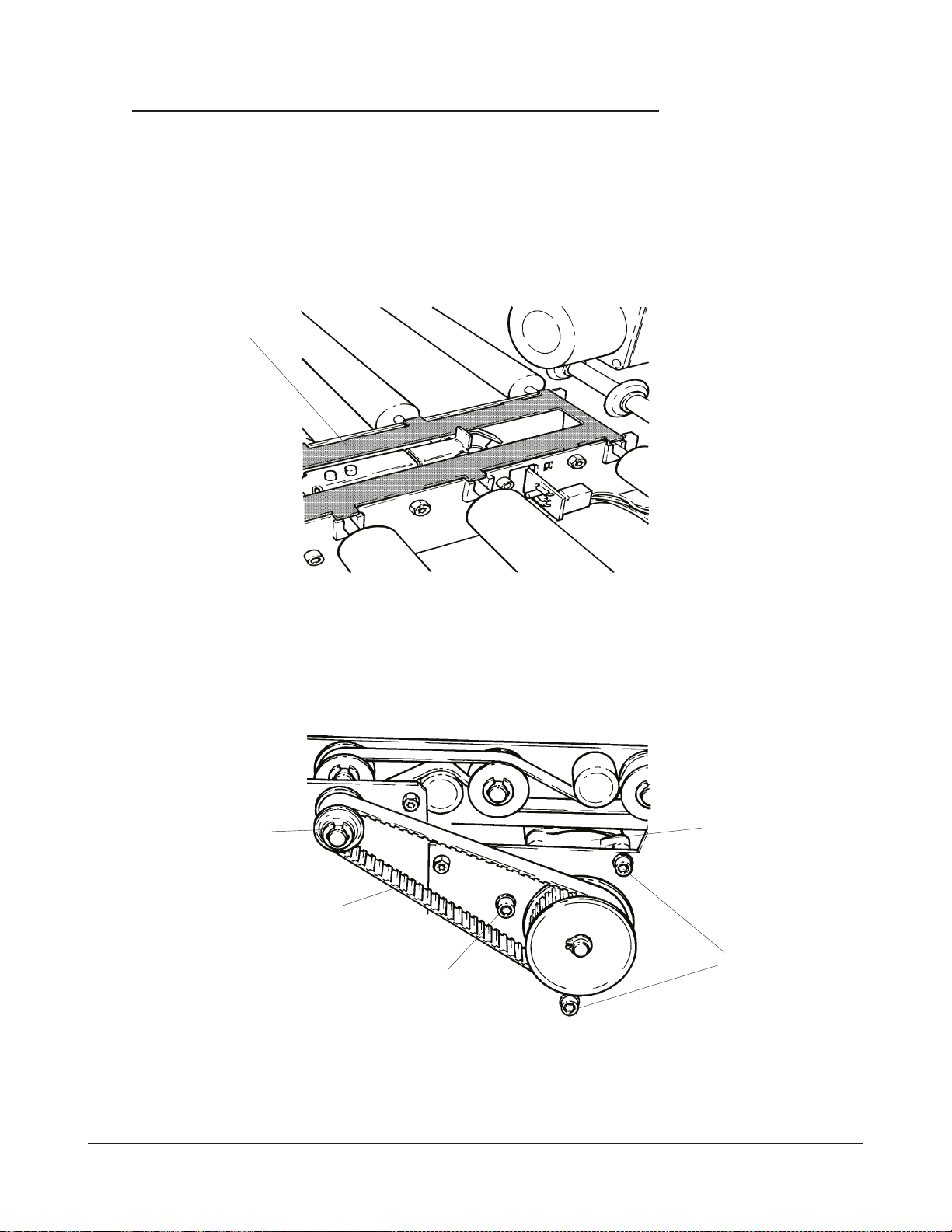
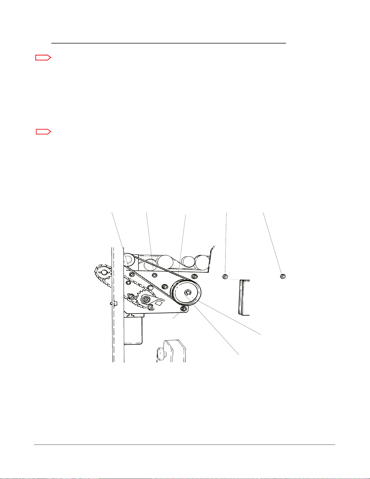
4. Loosen the MOUNTING SCREWS of the CASSETTE TRANSPORT MOTOR to take
off the TIMING BELT tension.
REAR
SMALL DRIVE
PULLEY
TRANSPORT MOTOR
FRONT
CASSETTE
TIMING BELT
MOUNTING
MOUNTING SCREW
figure 2-7
SCREWS
5. Take off the small DRIVE PULLEY with the TIMING BELT.
KODAK AG, Stuttgart 2-7 9/98
Page 20
SM 3058-6 REPLACEMENTS
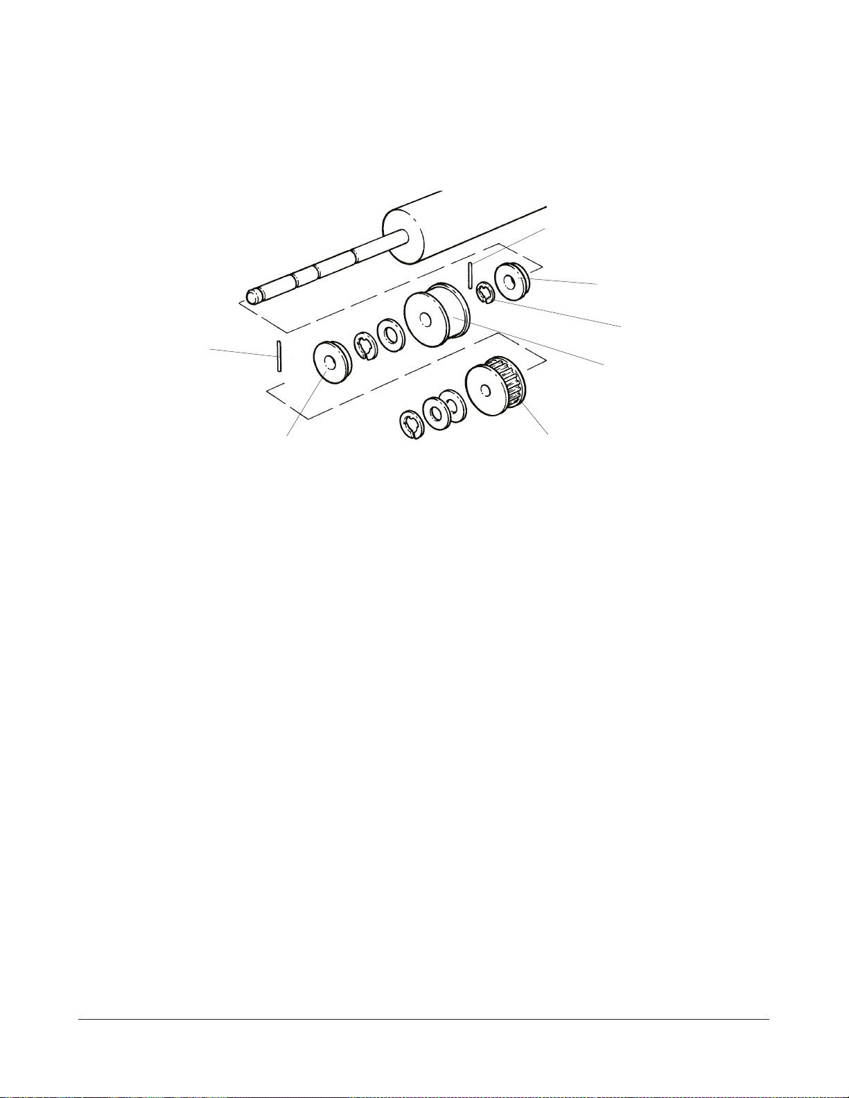
6. Take off the DOWEL PIN and the BEARING.
DOWEL PIN
BEARING
C-RING
DOWEL PIN
PLASTIC DRIVE
PULLEY
BEARING
figure 2-8
SMALL DRIVE PULLEY
7. TakeofftheleftsideDRIVEBELT.
8. Take off the C-RING, WASHER and the DOWEL PIN of the PLASTIC DRIVE
PULLEY.
9. Take off the TRANSPORT ROLLER DRIVE BELT on the right side.
10. Remove the right-hand CENTRING BAR from the MOUNTING BRACKET. To do
so take out the 2 MOUNTING SCREW S and lift up the right-hand TRANS PORT
ROLLERS with their BEARING SIDE.
11. Take off the right-hand PLASTIC PULLEY and BEARING of the TRANSPORT
ROLLER.
12. Shift the TRANSPORT ROLLER fully to the left until it stops.
13. Lift the right end of the TRAN SPORT ROLLER up and slide it out to the right.
14. Install new the TRANSPORT ROLLER.
9/98 2-8 KODAK AG, Stuttgart
Page 21
REPLACEMENTS SM 3058-6
FUNCTION TEST.
1. Check that a CASSETTE is transported correctly forward and backward.
REPLACEMENT OF THE CASSETTE WIDTH TIMING BELT.
1. Switch off the ML300.
2. Open the TOP COVER.
3. Remove the COVE R PLATE .
COVER PLATE
REAR
4. Take out the left GUID E.
FRONT
FRONT
figure 2-9
REAR
MOUNTING
LEFT GUIDE
figure 2-10
KODAK AG, Stuttgart 2-9 9/98
SCREWS
HOLDING
FINGER
Page 22
SM 3058-6 REPLACEMENTS
5. Loosen the MOUNTING SCREWS of the HOLDING FINGER.
6. Take out the HOLDING FINGER.
7. Take out BOARD A10 (ODOMETER CASSETTE WIDTH).
PCB A10
figure 2-11
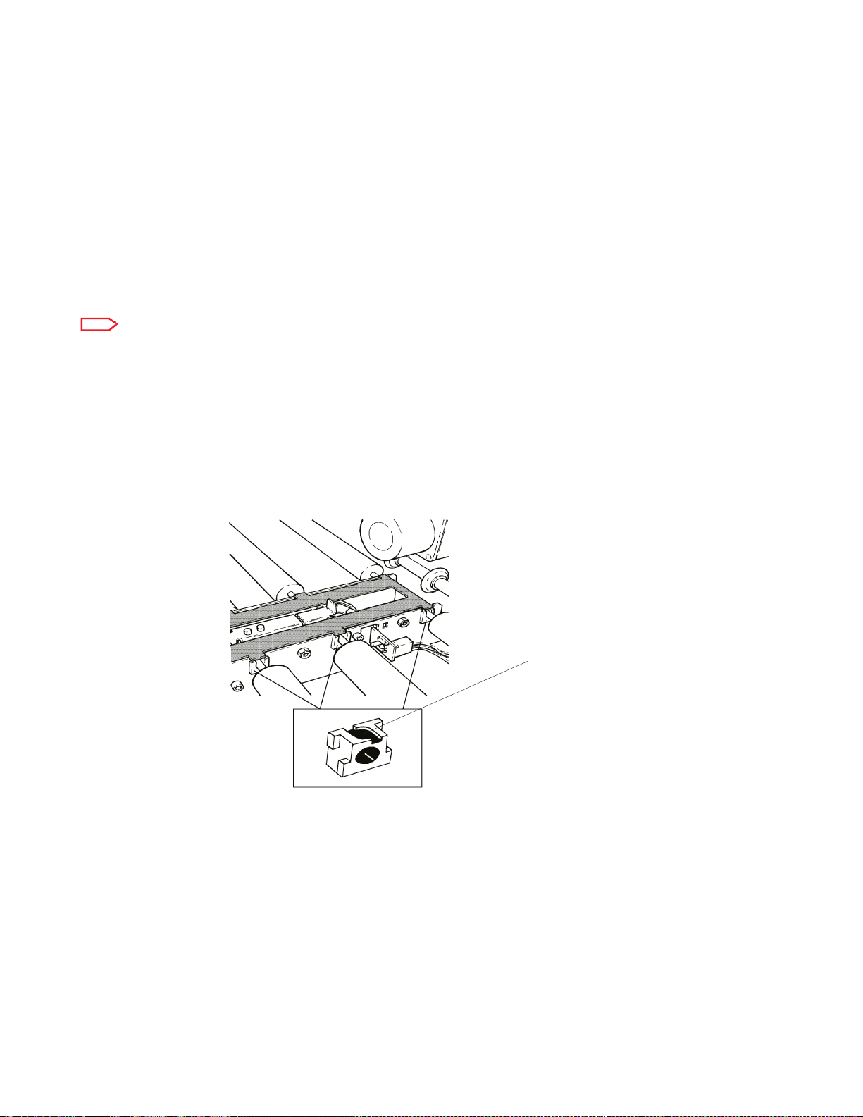
8. Take out the right C-RINGS of the 2 CASSE TTE TIMING BELT SHAFTS.
FRONT
TIMING BELT
SHAFT
C-RING
SET SCREW
PIN
CLUTCH
figure 2-12
REAR
C-RING
TIMING BELT
SHAFT
9. Loosen the CLUTCH SE T SCREWS and take out the PIN.
9/98 2-10 KODAK AG, Stuttgart
Page 23
REPLACEMENTS SM 3058-6
10. Lift out the short TRANSPORT ROLLER near to the ODOMETER.
short TRANSPORT
ODOMETER
ROLLER
figure 2-13
11. Shift both CA SSETTE TIMING BELT SHAFTS to the left.
12. Replace the TIMING BELT.
13. When installing the HOLDING FINGER, make sure that the TIMING BELT is
centred before you tighten the MOUNTING SCREWS.
14. The ODOMETER (PCB A10) has to be positioned as shown.
CODE DISC
On this side of the CODE DISC
is an imprinted number
21.3 ± 0.5 mm
PCB A10
This corner is cut at an angle
1.2 mm max. for new style PCBs
0.5 mm max. for old style PCBs
0.1 mm min. for both styles.
figure 2-14
KODAK AG, Stuttgart 2-11 9/98
Page 24

SM 3058-6 REPLACEMENTS
15. If the distance of 21.3mm is not correct, loosen the MOUNTING SCREW of the
PCB HOLDER and move it as required.
Note
Not all PCB A10 are working correctly when the gap is set to 1 .2 mm. Espec ially with the
old style PCBs the g ap should not be bigger than 0.5 mm.
16. If the distance of 1mm is not correct, loosen the MOUNTING SCREWS of PCBA10
and move it as re quired.
17. If the PCB cannot be moved fa r enough, take it out and elongate the MOUNTING
SCREW HOLES with a small file.
FUNCTION TEST
1. FeedinaCASSETTE.
2. Check that the HOLDING FINGER transports the CASSETTE up to the CASSETTE
END STOP.
3. Check that the correct CASSETTE SIZE is detected.
9/98 2-12 KODAK AG, Stuttgart
Page 25
REPLACEMENTS SM 3058-6
REPLACEMENT OF THE CASSETTE TRANSPORT MOTOR M2.
Note
Always order MOTOR PN 9228010 and RETAINING RING PN 450016
1. Switch off the ML300.
2. Take off the PANELS.
Note
THE DOWEL PIN MAY FALL DOWN
3. Take off the DRIVE PULLEY with the D OWEL PIN and the TIMING B ELT.
SCREW 3
SCREW 1 SCREW 2 TIMING BELT SCREW 4 SCREW 5
PCB A9
MOUNTING
SCREW (3)
DRIVE PULLEY WITH
DOWEL PIN
RETAINING RING
figure 2-15
KODAK AG, Stuttgart 2-13 9/98
Page 26
SM 3058-6 REPLACEMENTS
4. Loosen SCREWS 1, 2 and 3. Se e figure 2-15.
5. Take out SCREWS 4 and 5. See figures 2-15.
Note
The SPACERS between the MOTOR and the MOUNTING BRACKET may fall down.
6. Take out the MOUNTING SCREWS of the CA SSETTE TRANSPORT MOTOR.
MOUNTING SCREW
MOUNTING
SCREW
figure 2-16
7. Take out the CASSETTE TRANSPORT MOTOR.
8. Install the new MOTOR.
9/98 2-14 KODAK AG, Stuttgart
Page 27

REPLACEMENTS SM 3058-6
FUNCTION TEST.
1. Start the CASSETTE TRANSPORT MOTOR M2
Start the SERVICE PROGRAM
Select SERVICE MODE from the GLOBAL MENU....................................... press ENTER
ENTER SERVICE MODE MESSAGE is displayed............................................press ENTER
UNIT Data are displayed ...............................................................................press ENTER
Select COMPONENT TEST from the MAIN MENU.......................................press ENTER
Select CASSETTE MOTORS ...............................................................................press ENTER
Select CASSETTE TRANSPORT M2 ...................................................................press ENTER
2. Check that the MOTOR is running forward/backward.
Select FORWARD/BACKWARD
3. Exit the SERVICE PROGRAM
Press 3 times BACKSPACE
Select LEAVE COMPONENT TEST ...................................................................press ENTER
Select QUIT ML300 SERVICE MODE............................................................... press ENTER
Select Quit the program................................................................................. press ENTER
KODAK AG, Stuttgart 2-15 9/98
Page 28
SM 3058-6 REPLACEMENTS
REPLACEMENT OF THE CASSETTE OPENER MOTOR M5
1. Switch off the ML300.
2. Remove the PANE LS.
3. Take off the ACTUATOR
MOUNTING
SCREW (3)
CASSETTE
OPENER
MOTOR
OPENER
STOP PLATE
MOUNTING
SCREW (3)
OPENER STOP
PLATE
PCB A9
SENSOR B15
DRIVE GEAR
ACTUATOR
figure 2-17
4. Take out MOUNTING SCREWS of CASSETTE OPENER MOTOR.
5. Mark the position of the OPENER STOP PLATE.
6. Take out the MOUNTING SCREWS of the OPENER STOP PLATE.
7. Take out the DOWEL PIN of the MOTOR SHAFT.
8. Take out the STOP PLATE .
9/98 2-16 KODAK AG, Stuttgart
Page 29
REPLACEMENTS SM 3058-6
Warning
Hold with one hand the CASSETTE OPENER MECHANISM. As soon as you take off the
CHAIN, the mechanism moves down and may squeeze in your fingers . When the t he GEAR
is off lower the CASSETTE OPENER MECHANISM to its bottom position.
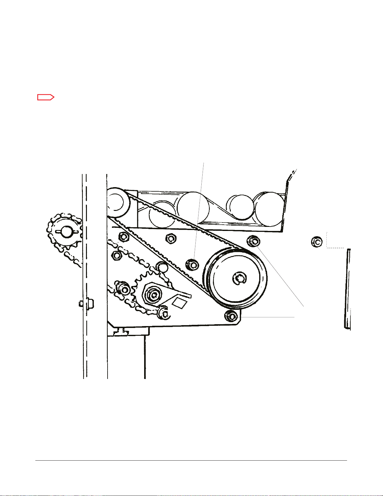
9. Take off the DRIVE GEAR with the CHAIN.
10. TakeoutSCREW1to5.
SCREW 1 2 3 4
SCREW 5
PCB A9
CASSETTE
OPENER
MOTOR
figure 2-18
11. Pull the MOUNTING PLATE forward a s far as possible.
Note
The MOTOR comes off with a THREAD P LATE. This THREAD PLATE must be inserted again
with the new MOTOR. It holds the OP ENER STOP PLA TE.
12. Take out the CASSETTE OPENER MOTOR.
13. Insert the new CASSETTE OPENER MOTOR together with the THREAD PLATE.
KODAK AG, Stuttgart 2-17 9/98
Page 30

SM 3058-6 REPLACEMENTS
14. Insert and fasten SCREW 1 to 5.
15. Insert the 3 MOTOR MOUNTING SCRE WS. Do not fasten them. Mount SENSOR
B15/C_OP_EO.
16. Mount the OPENER STOP PLATE. Use the marks made in step 5 as reference.
Tighten the MOUNTING SCREWS just a bit, that the STOP PLATE can s till be moved.
Warning
BE CAREFUL WHEN WORKING IN THE CASSETTE OPENER AREA. THE OPENER MOTOR
AND THE OPENER MECHANISM ARE VERY STRONG. THEY CANNOT BE MOVED
MANUALLY. THEY MAY SQUEEZE YOUR HAND AND TRAP YOU IF YOU TRY TO STOP
THEM MANUALLY. NEVER START THE CASSETTE OPE NER MOTOR WHEN SOMEONE’S
HANDS ARE IN THE CASSETTE AREA.
17. Switch on the ML300
DOWEL PIN should be
in a horizontal position
DOWEL PIN GROOVE
figure 2-19
18. To mount the MOTOR D RIVE GEAR the D OWEL PIN has to be in the correct
position in relation to the STOP BOLTS of the STOP PLATE.
To rotate the MOTOR SHAFT use the SERVICE PROGRAM. Switch on the CASSETTE
OPENER MOTOR M5 until the DOWEL PIN is in a horizontal position.
9/98 2-18 KODAK AG, Stuttgart
Page 31

REPLACEMENTS SM 3058-6
Select SERVICE MODE from the GLOBAL MENU....................................... press ENTER
ENTER SERVICE MODE MESSAGE is displayed............................................press ENTER
UNIT DATA are displayed ................................................................................ press ENTER
Select COMPONENT TEST from the MAIN MENU.......................................press ENTER
Select CASSETTE MOTORS ...............................................................................press ENTER
Select CASSETTE OPENING M5.......................................................................press ENTER
Select DOWN or UP unti l the DOWEL PIN is in a horizontal position.
Note
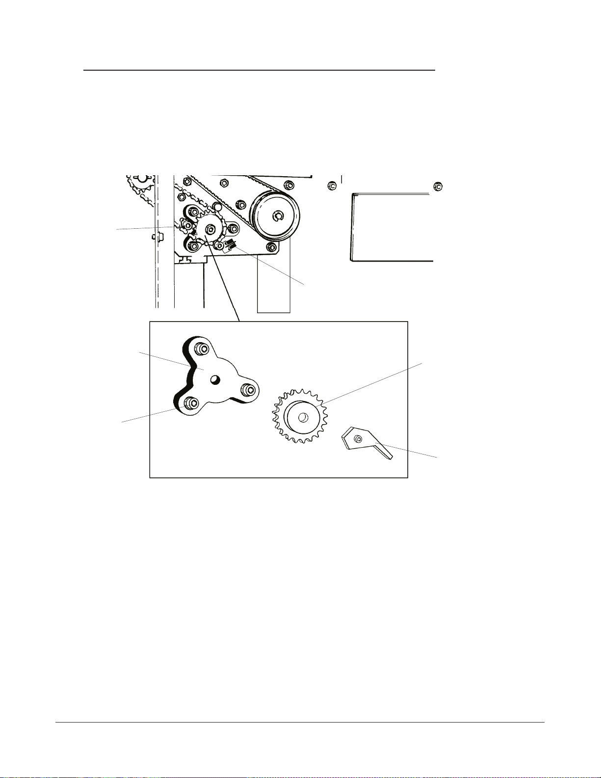
The STOP PIN of the DRIVE GEAR has to be to the left of the bottom STOP BOLT. If it is to
the right, the CASSETTE OPENER cannot mo ve for the co rrect distance.
19. Mount the DRIVE GE AR onto the MOTOR SHAFT. Ensure that it is seated properly
ontheDOWELPIN.MounttheACTUATORremovedinstep3toholdtheDRIVEGEAR
on the SHAFT. Do not tighten the ACTUATOR SCREW at this time.
OPENER STOP PLATE
DRIVE GEAR
bottom STOP BOLT
STOP PIN
figure 2-20
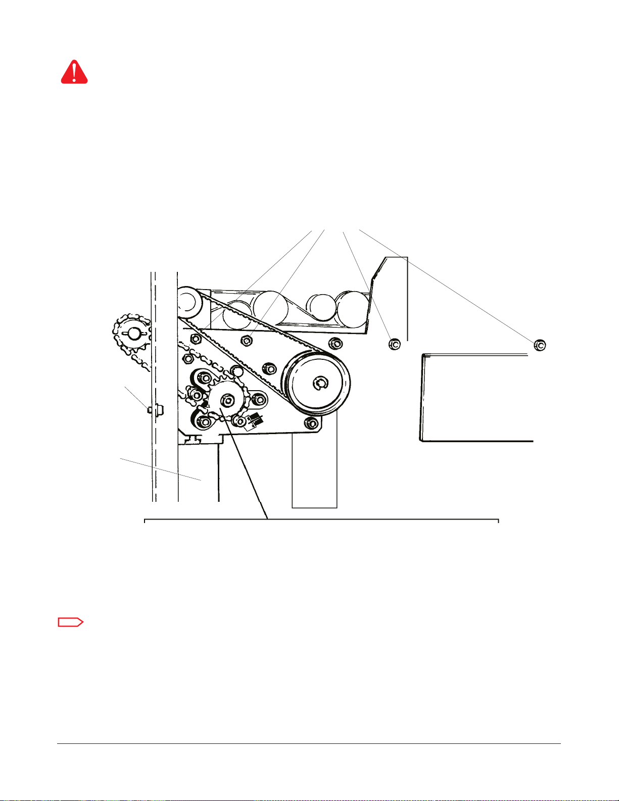
20. To mount the CHAIN is the next step. To do this the CASSETTE OPENER
MECHANISMandtheMOTORDRIVEGEARhavetobeinthecorrectposition.
a. The CASSETTE OPENER MECHANISM must be in its bottom position.
b. The STOP PIN of the DRIVE GEAR should just touch the bottom STOP BOLT of
the STOP PLATE.
Select DOWN until the STOP PIN just touches the STOP BOLT.
KODAK AG, Stuttgart 2-19 9/98
Page 32

SM 3058-6 REPLACEMENTS
21. Take off the SMALL GEAR.
SMALL GEAR
C-RING
figure 2-21
22. Mount the CHAIN onto the MOTOR DRIVE GEAR and onto the SMALL GEAR.
23. Put the small GEAR onto its SHAFT and secure it with the C-RING.
24. Tension the CHAIN by moving the CASSETTE OPENER MOTOR to the right.
25. Tighten the MOTOR MOUNTING SCREW S.
26. Move the CASSETTE OP ENER to its fully up position.
Select UP until the OPENER BRACKET is vertical.
9/98 2-20 KODAK AG, Stuttgart
Page 33

REPLACEMENTS SM 3058-6
The OPENER
BRACKET must
be vertical
figure 2-22
27. Adjust the ACTUATOR that SENSOR B 15 is actuated. Tighten its MOUNTING
SCREW.
SENSOR B15
ACTUATOR
2-23
KODAK AG, Stuttgart 2-21 9/98
Page 34

SM 3058-6 REPLACEMENTS
28. The ACTUATOR must now be set to a position that the CA SSETTE OPENER
MOTOR is switched off as soon as the OPENER B RACKET is vertical.
Select DOWN until the OPENER is fully down
Select UP until the OPENER stops
29. If the OPE NER BRAC KET is vertical p roceed with step 30. If not proceed here.
Reposition the ACTUATOR as required and proceed with step 28.
30. SENSOR B15 is now adjusted correct ly. The next s tep is to adjust the OPENER
STOP PLATE.
Note
It is not possible to s ee this gap. You have to set it by feeling.
31. The OPENER is still in the upper position. Turn the STOP PLATE
counter-clockwise until the STOP BOLT touches the STOP PIN of the DRIVE GEAR.
Turn the STOP PLATE clockwise until there is a gap of approximately 1mm between
the STOP PIN and the STOP BOLT.
32. Tighten the MOUNTING SCREW S of the STOP PLA TE.
33. Check the position of the STOP PLATE.
-Disconnect SEN SOR B15(CONNECTOR X9)
-Select U P. The MOTOR M5 must turn for a short distance and is stopped then.
A high pitched tone can be heard at the same time.
-Connect SENSOR B15.
-Select DOWN until the CASSETTE OPENER stops in its bottom position.
-Manually actuate SENSOR B15. Do not break its thin PLASTIC ACTUATOR.
-Select DOWN again. MOTOR M5 should turn for a short distance and is
stopped then. A high pitched tone can be heard at the same time.
-Select UP until the CASSETTE OPENER stops in its uppermost position.
If the UP and DOW N positions are correct, proceed with s tep 34. Otherwise
reposition the STOP PLATE and repeat step 33.
34. Exit the SERVICE MODE.
Press 3 times BACKSPACE
Select LEAVE THE COMPONENT TEST .......................................................... press ENTER
Select QUIT ML300 SERVICE MODE............................................................... press ENTER
Select Quit the program................................................................................. press ENTER
9/98 2-22 KODAK AG, Stuttgart
Page 35

REPLACEMENTS SM 3058-6
FUNCTION TEST.
Warning
BE CAREFUL WHEN WORKING IN THE CASSETTE OPENER AREA. THE OPENER MOTOR
AND THE OPENER MECHANISM ARE VERY STRONG. THEY CANNOT BE MOVED
MANUALLY. THEY MAY SQUEEZE YOUR HAND AND TRAP YOU IF YOU TRY TO STOP
THEM MANUALLY. NEVER START THE CASSETTE OPE NER MOTOR WHEN SOMEONE’S
HANDS ARE IN THE CASSETTE AREA.
1. Take out the MAGAZINES loaded with CUSTOMER FILMS to avoid film fogging.
2. Run several cycles with test films.
3. Check that the OPENER BRACKET is vertical when the CASSETTE is open.
4. Check that the CASSETTE is correctly c losed.
REPLACEMENT OF THE CASSETTE OPENER SOLENOID Y4.
1. Switch off the ML300.
2. Take off the PANELS.
3. Unplug the CASSETTE OPENER SOLENOID (Connector X40).
4. Take out the 2 NUTS from the CASSETTE OPENER SOLENOID.
CONNECTOR X40
NUT
figure 2-24
KODAK AG, Stuttgart 2-23 9/98
Page 36

SM 3058-6 REPLACEMENTS
5. Install the new CASSETTE OPENER SOLENOID.
6. Adjust the CAS SETTE OPENER SOLENOID.
Start the SERVICE PROGRAM
Select SERVICE MODE from the GLOBAL MENU .................................... press ENTER
ENTER SERVICE MODE MESSAGE is displayed............................................press ENTER
UNIT DATA are displayed ................................................................................ press ENTER
Select COMPONENT TEST from the MAIN MENU.......................................press ENTER
Select SOLENOIDS .............................................................................................press ENTER
Select CASSETTE OPENER Y4...........................................................................press ENTER
Select SOLENOID ON
7. If the OPENER SHOVEL is only just touching the OPENER PLATE, proceed with
step 9, else proceed with step 8.
NUTS
touching slightly
OPENER
PLATE
OPENER SHOVEL
figure 2-25
Do not turn the SOLENOID too far, the BLOCK LEVE R may slide under the LEVER STOP.
See the drawing on th e next page.
8. Loosen the NUTS and turn the OPENER SOLENOID Y4 until the OPENER SHOVEL
is just touching the OPENER PLATE. Tighten the NUTS.
9/98 2-24 KODAK AG, Stuttgart
Page 37

REPLACEMENTS SM 3058-6
OPENER
SOLENOID
OPENER PLATE
LEVER STOP
NUT
CLUTCH
OPENER SHOVEL
figure 2-26
BLOCK LEVER
9. Make sure that the C LUTCH can be moved slightly to left and right using low force
only.
10. Exit the SERVICE PROGRA M.
Press 3 times BACKSPACE
Select LEAVE COMPONENT TEST ...................................................................press ENTER
Select QUIT ML300 SERVICE MODE............................................................... press ENTER
Select Quit the program................................................................................. press ENTER
FUNCTION TEST.
1. To avoid fogging CUSTOMER FILMS load the MAGAZINES with TEST FILMS.
2. Run several cycles with different CASSETTES. Check that they are opened correctly.
3. Reload the MAGAZINES with CUSTOMER FILMS.
KODAK AG, Stuttgart 2-25 9/98
Page 38

SM 3058-6 REPLACEMENTS
MAGAZINE OPENER
REPLACEMENT OF THE MAGAZINE OPENER MOTOR M 14.
1. Switch off the ML300.
2. Take off the Panels.
3. Move the MAGAZINE OPEN ER to the “CLO SED” position.
4. Take out all MAGAZINES.
5. Move the MAGAZINE OPENER to the “OPENED” position.
6. Take out the 2 BRACKET MOUNTING SCREWS.
7. Take out the MOTOR CONNECTOR from the FRAME.
8. Take out the OPENER ASSEMBLY.
REAR
BRACKET
MOUNTING
SCREWS
FRONT
MOTOR MOUNTING SCREW (4)
CONNECTOR
GEAR
figure 2-27
9/98 2-26 KODAK AG, Stuttgart
Page 39

REPLACEMENTS SM 3058-6
9. Take off the GEAR.
10. Take o ut the MOTOR MOUNTING SCREWS.
11. Install the new MAGAZINE OPENER MOTOR.
12. Move the MAGAZINE OPENER MOTOR to the “CLOSED” position.
13. Fasten the MOUNTING SCREWS.
14. Do the MAGAZINE OPENER MOTOR ADJUSTMENT as described in the section
ADJUSTMENT PROCEDURE S.
FUNCTION TEST.
No special FUNCTION TEST is necessary. The function of MOTOR M14 was tested during
the adjustments.
KODAK AG, Stuttgart 2-27 9/98
Page 40

SM 3058-6 REPLACEMENTS
FILM POCKET
REPLACEMENT OF THE FILM POCKET STEPPER MOTOR M10.
1. Switch off the ML300.
2. Take off the PANELS.
3. Take out the FILM CONVEYOR. See procedure REMOVAL OF CONVEYOR.
4. Loosen the STEPPER MOTOR MOUNTING SCREWS.
MOUNTING SCREW (4)
THREAD PLATE
CHAIN
STEPPER MOTOR
DOWEL PIN
C-RING
SPROCKET
figure 2-28
5. Take off theCHAIN from the SPROCKET.
9/98 2-28 KODAK AG, Stuttgart
Page 41

REPLACEMENTS SM 3058-6
Note
Take care of the DOWEL PIN it may fall down.
6. Take off the C-RING and take out the SPRO CKET.
7. Take out the STEPPER MOTOR MOUNTING SCREW S.
8. Install new the STEPPER MOTOR.
9. Move the STEPPER MOTOR up to tension the CHAIN.
10. Tighten the MOUNTING SCREWS.
FUNCTION TEST
1. To test the function of the FILM POCKET STEPPER MOTOR do a SCAN RUN.
Start the SERVICE PROGRAM.
Select SERVICE MODE from the GLOBAL MENU....................................... press ENTER
ENTER SERVICE MODE MESSAGE is displayed............................................press ENTER
UNIT DATA are displayed ................................................................................ press ENTER
Select CHANGE ML300 DATA from the MAIN MENU ............................... press ENTER
Select CHANGE PARAMETER.......................................................................... press ENTER
Select SCAN RUN ..............................................................................................press ENTER
Select STORE PARAMETERS .............................................................................press ENTER
2. Exit the SERVICE PROGRAM
Press BACKSPACE twice
Select QUIT ML300 SERVICE MODE............................................................... press ENTER
Select Quit the program................................................................................. press ENTER
KODAK AG, Stuttgart 2-29 9/98
Page 42

SM 3058-6 REPLACEMENTS
REPLACEMENT OF THE FILM POCKET SUCKER BAR MOTOR M15.
1. Switch off the ML300.
2. Take off the PANELS.
3. Take out the FILM CHUTE.
4. Cut the WIRE TIE and unplug the FILM POCKET MOTOR.
!
Caution
HOLD THE MOTOR. IT MIGHT FALL DOWN.
5. Take out the 4 MOUNTING SCREWS.
GEAR FILM POCKET DRIVE SHAFT
CHAIN
FILM POCKET MOTOR
DOWEL PIN
MOUNTING
SCREW (4)
FILM POCKET
DRIVE SHAFT
WIRE TIE
figure 2-29
9/98 2-30 KODAK AG, Stuttgart
Page 43

REPLACEMENTS SM 3058-6
Note
Use the DOWEL PIN and the GEAR from the old MOTOR.
6. Install the new FILM POCKET MOTOR.
FUNCTION TEST.
1. Take out all MAGAZINES.
2. Check that the FILM POCKET SUCKER BAR ARM m oves forward and backward.
Start the SERVICE PROGRAM
Select SERVICE MODE from the GLOBAL MENU....................................... press ENTER
ENTER SERVICE MODE MESSAGE is displayed............................................press ENTER
UNIT DATA are displayed ................................................................................ press ENTER
Select COMPONENT TEST ................................................................................press ENTER
Select MAGAZINE MOTORS ............................................................................press ENTER
Select FILM PICK UP MAGAZINE M15...........................................................press ENTER
Select f orward and backward
3. Exit the SERVICE PROGRAM
Press 3 times BACKSPACE
Select LEAVE COMPONENT TEST ...................................................................press ENTER
Select QUIT ML300 SERVICE MODE............................................................... press ENTER
Select Quit the program................................................................................. press ENTER
KODAK AG, Stuttgart 2-31 9/98
Page 44

SM 3058-6 REPLACEMENTS
REPLACEMENT OF FILM POCKET TORSION SPRING (SN < 2000).
Note
· If modification 34 is installed proceed with page 2-35
· AFTER THE TORSION SPRING IS REPLACED DO ALL THE FILM POCKET
ADJUSTMENTS.
1. Switch off the ML300.
2. Take off the PANELS.
RIGHT FILM GUIDE
TIMING DISKS
FILM POCKET
MOTOR
COLLAR WITH
SET SCREW
PCB A5
SCREW (2)
LEFT FILM GUIDE
MOUNTING
figure 2-30
3. Rotate out the FILM CHU TE.
4. Take out BOARD A5 together with the MOUNTING BRACKET.
Note
DETENT ASSY
SCREW (2)
DETENT ARM
BRACKET
Starting with SN 1422 a DOU BLE DETENT is use d. See the figure on the next page.
5. Take out the DETENT ASSEMBLY.
9/98 2-32 KODAK AG, Stuttgart
Page 45

REPLACEMENTS SM 3058-6
FILM REJECTER ASSY
right-hand NUT
TORSION
6. Take out the right FILM GUIDE.
DETENT
ASSY
PCB A5
SPRING
figure 2-31
7. Remove the right-hand NUT of the FILM REJECTER AS SEMBLY
8. Take of the TIMING DISKS.
9. Slide out the right-hand side FILM REJECTER ASSEMBLY and the C AMS with the
TORSION SPRING.
KODAK AG, Stuttgart 2-33 9/98
Page 46

SM 3058-6 REPLACEMENTS
Note
The TORSION SPRING is installed correctly if the FILM REJECTER ASSEMBLY rests at the
rear MAGAZINE WALL after the FILM P OCKET SUCKER BAR ARM is rotated in the upright
(vertical ) position.
10. Install the new SPRING.
11. Do the FILM POCKET ADJUSTMENTS.
FUNCTION TEST.
1. Chec k that s mall and large FIL MS are pick ed up corre ctly from the magazines.
9/98 2-34 KODAK AG, Stuttgart
Page 47

REPLACEMENTS SM 3058-6
REPLACEMENT OF FILM POCKET TORSION SPRING (SN > 2000).
Note
AFTER THE TORSION SPRING IS REPLACED, NO FILM POCKET ADJUSTMENTS is
required.
1. Switch off the ML300.
2. Take off the PANELS.
3. Rotate out the FILM CHU TE.
4. Loosen the SET SCREW of the COLLAR at the right-hand FILM REJECTER.
SET SCREW
figure 2-32
KODAK AG, Stuttgart 2-35 9/98
Page 48

SM 3058-6 REPLACEMENTS
5. Slide the right-hand CLUTC H DISK to the right and take out the defective CLUTCH
SPRING.
6. Lubricate the RING an d the right-hand CLUTCH DISK as sh own to avoid wear and
install the new CLUTCH DISK.
lubricate this surface
right-hand
CLUTCH DISK
lubricate this surface
RING
figure 2-33
7. Slide the right-hand CLUTCH D ISK, the right-hand FILM REJECTER and the
COLLAR to the left. Tighten the SET SCREW.
8. Ensure that the CLUTCH SPRING is mounted as shown.
CLUTCH SPRING
figure 2-34
9/98 2-36 KODAK AG, Stuttgart
Page 49

REPLACEMENTS SM 3058-6
FUNCTION TEST.
1. Chec k that s mall and large FIL MS are pick ed up corre ctly from the magazines.
REPLACEMENT OF THE FILM POCKET CLUTCH SPRING (SN > 2000)
Note
After the replacement of this SPRING no adjustment is necessar y.
1. Switch off the ML300.
2. Remove the REAR PANEL.
3. Take out the 6 FILM CHUTE MOUNTING SCREW S. With SN > 3000 there is just 1
MOUNTING SCREW.
MOUNTING
SCREW
SN < 3000
MOUNTING SCREW
SN < 3000
figure 2-35
MOUNTING
SCREW
SN < 3000
MOUNTING
SCREW
SN > 3000
MOUNTING
SCREW
SN < 3000
FILM CHUTE
KODAK AG, Stuttgart 2-37 9/98
Page 50

SM 3058-6 REPLACEMENTS
4. Rotate out the FILM CHU TE.
5. Loosen the SET SCREW of the COLLAR and shift the COLLAR to the right.
SET SCREW
figure 2-36
9/98 2-38 KODAK AG, Stuttgart
Page 51

REPLACEMENTS SM 3058-6
Note
It is not necessary to unhook the REJECTER SPR ING (SPRING between REJECTER and
PCB A5).
6. Loosen the SPRING HOOK NUTS on the right-hand REJECTER, so that the
REJECTERcanbeshiftedafewmillimetrestotheright.
7. Shift the CLUTCH DISK 2 to the right. If necessary push the STOP PLATE a little
forward. Do not loosen the STOP PLATE. This would alter the end positions of
the REJECTER.
8. Take out the old CLUTCH SPRING.
9. Install the new SPRING.
10. Shift CLUTCH DISK 2 fully to the left. Ensure that CLUTCH DISK 1 is engaged
with the FILM POCKET ARM.
11. Move the COLLAR fully to the left and tighten its SET SCRE W.
12. Tighten the SPRING HOOK NUTS on the right-hand REJECTER.
13. Rotate in the FILM CHUTE and fix it with the 6 MOUNTING SCREWS
(or1forSN>3000)fromstep3.
14. Mount the REAR PANEL
FUNCTION TEST
1. Switch on the ML300.
2. Run a few cycles with different film sizes to check for correct operation.
KODAK AG, Stuttgart 2-39 9/98
Page 52

SM 3058-6 REPLACEMENTS
REPLACEMENT OF THE FILM REJECTER SPRING
1. Switch off the ML300.
2. Remove the REAR PANEL.
3. Take out the 6 FILM CHUTE MOUNTING SCREW S. With SN > 3000 there is just 1
MOUNTING SCREW.
4. Rotate out the FILM CHU TE.
MOUNTING
SCREW
SN < 3000
MOUNTING SCREW
SN < 3000
figure 2-37
MOUNTING
SCREW
SN < 3000
MOUNTING
SCREW
SN > 3000
MOUNTING
SCREW
SN < 3000
FILM CHUTE
9/98 2-40 KODAK AG, Stuttgart
Page 53

REPLACEMENTS SM 3058-6
5. Unhook the old REJECTER SPRING.
6. Install the new REJECTER SPRING.
REJECTER SPRING
figure 2-38
KODAK AG, Stuttgart 2-41 9/98
Page 54

SM 3058-6 REPLACEMENTS
7. Manually rotate in and out the FILM POCKET SUCKER BAR ARM and check that
the REJECTER moves correctly forward and backward.
8. Rotate in the FILM CHUTE and fix it with the 6 MOUNTING SCREWS
(or1forSN>3000)fromstep3.
9. Mount the REAR PANEL.
PROCESSOR INTERFACE
REPLACEMENT OF PROCESSOR INTERFACE MOTOR M13
1. Switch off the ML300.
2. Take off the PANELS.
3. Take off the MOTOR CONNECTOR on BOARD A5 X25.
4. Take out the INTERFACE ASSEMBLY.
5. Take off the DRIVE BELT.
6. Take off the MOTOR MOUNTING SCREWS.
7. Install the new MOTOR.
DRIVE BELT
INTERFACE MOTOR
(mounted to the inner side
of the interface)
figure 2-39
9/98 2-42 KODAK AG, Stuttgart
Page 55

REPLACEMENTS SM 3058-6
FUNCTION TEST.
1. Check that the PROCESSOR INTERFACE MOTOR is running.
Start the SERVICE PROGRAM
Select SERVICE MODE from the GLOBAL MENU....................................... press ENTER
ENTER SERVICE MODE MESSAGE is displayed............................................press ENTER
UNIT DATA are displayed ................................................................................ press ENTER
Select COMPONENT TEST ................................................................................press ENTER
Select INTERFACE/FILM MOT........................................................................... press ENTER
Select MAGAZINE ROLLER MOTOR M13 ...................................................... press ENTER
Select ON /OFF
2. Exit the SERVICE PROGRAM
Press 3 times BACKSPACE
Select LEAVE COMPONENT TEST..................................................................press ENTER
Select QUIT ML300 SERVICE MODE............................................................... press ENTER
Select Quit the program................................................................................. press ENTER.
PROCESSOR INTERFACE CLUTCHES
There are 2 free running ONE_WAY CLUTCHES in the PROCESSOR INTERFACE PULLEYS.
If you pull a FILM through the PROCESSOR INTERFACE in direction of the PROCESSOR
the toothed BELT must not move. If it moves as you pull, one of the free running ONE-WA Y
CLUTCHES is assembled wrong.
This ARROW must be on the visible side of the
CLUTCH and must point into the indicated direction. It
is possible that the ARROW is covered by the C-RING
figure 2-40
KODAK AG, Stuttgart 2-43 9/98
Page 56

SM 3058-6 REPLACEMENTS
CONVEYOR
REMOVAL OF THE CONVEYOR
1. Switch off the ML300.
2. Take off the PANELS.
3. Disconnect CONNEC TOR X55 and CON NECTOR X60.
CONNECTOR X60
CONNECTOR X55
figure 41
9/98 2-44 KODAK AG, Stuttgart
Page 57

REPLACEMENTS SM 3058-6
4. Cut the WIRE TIE and mark the position of it.
WIRE TIE
figure 2-42
5. Disconnect the HOSE and carefully pull it out o ff the CABLE DUCT.
Disconnect the
HOSE here
CABLE DUCT
figure 2-43
KODAK AG, Stuttgart 2-45 9/98
Page 58

SM 3058-6 REPLACEMENTS
6. Remove the SCREW S from each of the RETAINERS on each side of the
CONVEYOR.
RETAINER
RETAINER
RETAINER
7. Takeoffthe2SUPPORTS.
figure 2-44
SUPPORT
figure 2-45
9/98 2-46 KODAK AG, Stuttgart
SUPPORT
Page 59

REPLACEMENTS SM 3058-6
8. Lift out the CONVEY OR.
FUNCTION TEST
1. Check that the CON VEYOR is seat ed properly. It must be as far as possible to the
front (e.g. to the INPUT F LAP).
2. Check that the HOS E is connec ted again and th at it is routed through the CABLE
DUCT.
3. Check that the HARNESS is fixed with a WIRE TIE at the correct place. Use the
mark from step 4 as reference.
4. Check that CONNECTOR S X55 and X60 are seated properly .
5. Run TEST CYCLES with different film sizes and check that the FILM is picked up
from the CASSETTE.
6. Check that the FILM is transported correctly into the FILM CHUTE.
DISASSEMBLY OF THE CONVEYOR
Disassembly of the CONVEYOR is needed for removing the following:
· DRIVE SHAFTS
· CARRIAGE ASSEMBLY
· DRIVE BELTS
1. Do PROCEDURE “REMOVAL OF CONVEYOR”.
2. Cut the WIRE TIES along the upper TIERODS. Mark the position of the WIRE TIES.
See the top drawing on the next page.
3. Take out the 4 NUTS at the TIERODS.
4. Remove the 12 C-R INGS from the upper 2 TIERODS.
5. Remove the CARRIAGE STOP.
6. Slide out both upper TIE RODS.
KODAK AG, Stuttgart 2-47 9/98
Page 60

SM 3058-6 REPLACEMENTS
NUT
CARRIAGE
STOP
NUT
upper TIEROD
figure 2-46
7. Take out C-RINGS at both PRESSURE ROLLER SHAFTS and slide SHAFTS
outwards.
SPRING
PRESSURE ROLLER SHAFT
C-RING
figure 2-47
9/98 2-48 KODAK AG, Stuttgart
Page 61

REPLACEMENTS SM 3058-6
8. Take out SPRINGS.
9. Disconnect the VACUUM SOLENOID CONNECTOR.
10. Disconnect the GROUND WIRE at the ROLLER MOTOR.
11. Disconnect the CONNECTORS of both CARRIAGE POSITION SENSORS.
12. Disconnect the CONNECTOR of the SENSOR VACUUM OFF.
Note
Do not lose the SPACER of the PRESSURE ROLLER SHAFT located on the ROLLER
MOTOR side.
13. Carefully lift out the CARRIAGE ASSEMBLY.
FUNCTION TEST
1. Check that the WIRE TIES are at the correct position. Use the marks from step 4 as
reference.
2. Check that the CON VEYOR is seat ed properly. It must be as far as possible to the
front (e.g. to the INPUT F LAP).
3. Run a TEST CYCLE.
4. Check that the FILM is picked up from the CASSETTE.
5. Check that the FILM is transported correctly into the FILM CHUTE.
6. Use various FILM SIZES.
KODAK AG, Stuttgart 2-49 9/98
Page 62

SM 3058-6 REPLACEMENTS
REPLACEMENT OF THE FILM PICK UP MOTOR BELT (CARRIAGE)
1. Do Procedure “REMOVAL OF CONVEYOR”.
2. Remove the 3 MOUNTING SCREWS of the FILM PICK UP MOTOR.
MOUNTING SCREW
(3)
BELT
MOTOR M6
figure 2-48
3. Replace the BELT with a new one.
FUNCTION TEST
1. Check that the CON VEYOR is seat ed properly. It must be as far as possible to the
front (e.g. to the INPUT F LAP).
2. Run a TEST CYCLE.
3. Check that the FILM is picked up from the CASSETTE.
4. Check that the FILM is transported correctly into the FILM CHUTE.
5. Use various FILM SIZES.
9/98 2-50 KODAK AG, Stuttgart
Page 63

REPLACEMENTS SM 3058-6
REPLACEMENT OF FILM PICK UP MOTOR (CARRIAGE ) M6
1. Do PROCEDURE “REMOVAL OF CONVEYOR”.
2. Remove the 3 MOUNTING SCREWS.
3. Take out the 3 MOTOR WIRES from the CONNECTOR X60. Extraction Tool TL1580.
4. Take out the MOTOR.
CONNECTOR X60
figure 2-49
MOUNTING SCREW
(3)
MOTOR M6
figure 2-50
5. Install the new MOTOR.
KODAK AG, Stuttgart 2-51 9/98
Page 64

SM 3058-6 REPLACEMENTS
FUNCTION TEST
1. Check that the FILM PICK UP MOTOR M6 is running.
Start the SERVICE PROGRAM
Select SERVICE MODE from the GLOBAL MENU....................................... press ENTER
ENTER SERVICE MODE MESSAGE IS DISPLAYED.......................................... press ENTER
UNIT DATA are displayed ................................................................................ press ENTER
Select COMPONENT TEST ................................................................................press ENTER
Select CASSETTE MOTORS ...............................................................................press ENTER
Select FILM PICK UP M6...................................................................................press ENTER
Select forward ................................................................................................... press ENTER
Select backward ............................................................................................... press ENTER
2. Exit the SERVICE PROGRAM
Press 3 times BACKSPACE
Select LEAVE COMPONENT TEST ...................................................................press ENTER
Select Quit ML300 SERVICE MODE ............................................................... press ENTER
Select Quit the program................................................................................. press ENTER.
REPLACEMENT OF CARRIAGE ASS EMBLY DRIVE BELTS
Note
Replace both Drive Belts at the same time.
1. Do PROCEDURE “REMOVAL OF CONVEYOR”.
2. Do PROCEDURE “REPLACEMENT OF FILM PICK UP MOTOR” step 1 to 3.
3. Mark the position of the BEL T-LINKS on the MECHANISM PLATES. These m arks
areusedasareferencewheninstallingthenewDRIVEBELTS.
4. Remove the IDLER ROLLERS.
5. Remove the small C-RINGS at the BELT LINKS.
6. SlidetheGEARtotherightandremovetheDOWELPIN.
7. Slide the FILM PICK UP DRIV E SHAFT to the left.
9/98 2-52 KODAK AG, Stuttgart
Page 65

REPLACEMENTS SM 3058-6
Note
A CARRIAGE JAM OCCURS IF THE BELT LINKS ARE NOT ALIGNED WITH THE
REFERENCE MARKS FROM STEP 3.
8. Replace the BELTS.
IDLER ROLLER (2)
C-RING and
BELT LINK
FILM PICK UP DRIVE SHAFT
DOWEL PIN
figure 2-51
KODAK AG, Stuttgart 2-53 9/98
C-RING
Page 66

SM 3058-6 REPLACEMENTS
FUNCTION TEST
1. Check that the CON VEYOR is seat ed properly. It must be as far as possible to the
front (e.g. to the INPUT F LAP).
2. Run a TEST CYCLE.
3. Check that the FILM is picked up from the CASSETTE.
4. Check that the CASSETTE SUCKER BAR CARRIA GE moves freely forward and
backward.
5. Check that the FILM is transported correctly into the FILM CHUTE.
6. Use various FILM SIZES.
REPLACEMENT OF SOLENOID CASSETTE SUCKER BAR TILTING Y7
1. Do PROCEDURE “REMOVAL OF CONVEYOR”.
2. Put CARRIAGE ASSEMBLY upside down.
3. Pull CASSETTE SUCKER BAR carefully forward to get access to the SOLENOID
CASSETTE SUCKER BAR TILTING Y7.
OLD VERSION
PIN
NUT
SOLENOID
figure 2-52
9/98 2-54 KODAK AG, Stuttgart
Page 67

REPLACEMENTS SM 3058-6
NEW VERSION
NUT
PIN
figure 2-53
4. Remove the PIN to dis connect the ARMATU RE from the AC TUATOR.
5. Undo the NUT.
6. Cut the WIRE TIES.
7. Replace the SOLENOID.
FUNCTION TEST
1. Check that the SOLENOID CASSETTE SUCKER BAR TILTING Y7 tilts the
CASSETTE SUCKER BAR.
Start the SERVICE PROGRAM
Select SERVICE MODE from the GLOBAL MENU....................................... press ENTER
ENTER SERVICE MODE MESSAGE is displayed............................................press ENTER
UNIT DATA are displayed ................................................................................ press ENTER
Select COMPONENT TEST ................................................................................press ENTER
Select SOLENOIDS .............................................................................................press ENTER
Select SOLENOID ON........................................................................................press ENTER
Select SOLENOID OFF....................................................................................... press ENTER
KODAK AG, Stuttgart 2-55 9/98
Page 68

SM 3058-6 REPLACEMENTS
2. Exit the SERVICE PROGRAM
Press 3 times BACKSPACE
Select LEAVE COMPONENT TEST ...................................................................press ENTER
Select QUIT ML300 SERVICE MODE............................................................... press ENTER
Select Quit the program................................................................................. press ENTER.
REPLACEMENT OF THE SENSOR SUCKER BAR TILT B19
1. Switch off the ML300.
2. Take off the TOP COVER, the REAR and the RIGHT-HAND PANEL.
3. Manually move the CASSETTE SUCKER BA R to the front.
4. Take out SENSOR B19. Mark the position of the WIRE TIES.
SENSOR B19
For XML300 without the additional SEN-
SOR MOUNTING BRACKET. Make the
front of the MOUNTING CLIPS
0.8 to 1.0 mm shorter, as indicated
by the dark area. Use a file for it.
This SENSOR MOUNTING BRACKET is
used in XML300 with SN > 1260
figure 2-54
9/98 2-56 KODAK AG, Stuttgart
Page 69

REPLACEMENTS SM 3058-6
5. If you have a X ML300 without th e additional SENS OR MOUNTING B RACKET
proceedwithstep6.Otherwiseproceedwithstep9.
6. Make the front of the SENSOR MOUNTING CLIPS (B19) 0.8 to 1mm smaller and
mount it into the CARRIAGE ASSEMBLY. See the drawing on the previous page.
7. Move the SENSOR B1 9 forward in direction of the CASSETTE as far as possible
and fix it in this position with glue.
8. Proceed with s tep 10.
9. Install the new SENSOR into the SENSOR MOUNTING BRACKET.
10. Fix the harness with WIRE TIES. Use the marks from step 4 as reference.
FUNCTION TEST
1. Sw itch on the ML300.
2. Test the function of SENSOR B19 with the SENSOR TEST.
Start the SERVICE PROGRAM.
Select SERVICE MODE from the GLOBAL MENU....................................... press ENTER
ENTER SERVICE MODE MESSAGE is displayed............................................press ENTER
UNIT DATA are displayed ................................................................................ press ENTER
Select COMPONENT TEST ................................................................................press ENTER
Select SENSORS.................................................................................................. press ENTER
Select WITH/WITHOUT SOUND ........................................................................press ENTER
3. Manually tilt the CASSETTE SUCKER BAR. B19 must now be indicated ON.
4. Exit the SERVICE PROGRAM.
Press 3 time BACKSPACE
Select LEAVE COMPONENT TEST ...................................................................press ENTER
Select QUIT ML300 SERVICE MODE............................................................... press ENTER
Select Quit the program................................................................................. press ENTER.
KODAK AG, Stuttgart 2-57 9/98
Page 70

SM 3058-6 REPLACEMENTS
9/98 2-58 KODAK AG, Stuttgart
Page 71

ADJUSTMENTS SM 3058-6
3. ADJUSTMENTS
INTRODUCTION
In this section it is very often explained how to use the CES SERVICE SOFTWARE. The first
line tells always what should be performed. In the next lines it is explained how to reach this
goal. These additional explanations are printed italic and can be skipped if you are
experienced w ith the CES SERVICE SOFTW ARE.
EXAMPLE:
1. Start the CASSETTE INPUT FLAP MOTOR M1
Start the SERVICE PROGRAM.
Select SERVICE MODE from the GLOBAL MENU....................................... press ENTER
ENTER SERVICE MODE MESSAGE is displayed............................................press ENTER
UNIT DATA are displayed ...............................................................................press ENTER
Select COMPONENT TEST from the MAIN MENU.......................................press ENTER
Select CASSETTE MOTORS ...............................................................................press ENTER
Select INPUT FLAP MOT M1.............................................................................press ENTER
Select CLOSE/OPEN.......................................................................................... press ENTER
SENSORS and DAYLIGHT
The SENSORS are s ensitive to daylight and to room light. This can result in wrong
measurements when you do an adjustment, or a SENSOR becomes triggered and the ML300
tries to bring the various units to HOME POSITION. For this reason dim the light or cover the
SENSORS when yo u do the a djustments. Th is is espec ially important whe n you meas ure the
output voltage of a SENSOR.
KODAK AG, Stuttgart 3-1 9/98
Page 72

SM 3058-6 ADJUSTMENTS
FRAME LEVELLING
PURPOSE:
This adjustment makes s ure, the PROCE SSOR will roll out smoothly. If the FRAM E is not
levelled it may be possible that the MAGAZINE SUCKER BAR is n o longer parallel to the
MAGAZINES. This may result in FILM PICKUP problems. Also it is possible that a
MAGAZINE stays open.
1. Take out all MAGAZINES.
Note
TheoldstyleFILMCHUTEhasalwaystobefixedwith4SCREWS.ThenewstyleFILM
CHUTE is only fixed with one SCREW and can be rotated out.
2. Make sure that the FIL M CHUTE is in the correct place an d that it is fixed with all 4
MOUNTING SCREWS to the FRAME.
3. Place the LEVEL onto the BASE PLATE of the MAGAZINE CHAMBER.
MOUNTING
SCREW
FILM CHUTE
old style
FILM
CHUTE
MOUNTING
SCREW
MOUNTING
SCREW
MOUNTING
SCREW
MOUNTING SCREW
figure 3-1
9/98 3-2 KODAK AG, Stuttgart
Page 73

ADJUSTMENTS SM 3058-6
4. Adjust the 4 LEVELLING FEET until the FRAME is horizontal in the X and Y
direction.
figure 3-2
KODAK AG, Stuttgart 3-3 9/98
Page 74

SM 3058-6 ADJUSTMENTS
CASSETTE AREA
INPUT FLAP
PURPOSE:
This adjustment ensures that the INPUT FLAP is closed light-tight when a C ASSETTE is fed
into the MULTILOADER 300.
1. Take off the PANEL.
2. TakeofftheFRONTPANELwiththeDISPLAY.
3. Close the INPUT FLAP.
Start the SERVICE PROGRAM
Select SERVICE MODE from the GLOBAL MENU....................................... press ENTER
ENTER SERVICE MODE MESSAGE is displayed............................................press ENTER
Select COMPONENT TEST from the MAIN MENU.......................................press ENTER
Select CASSETTE MOTORS ...............................................................................press ENTER
Select CASSETTE INPUT FLAP M1.................................................................... press ENTER
Select CLOSE
4. Adjust SENSOR B4/C_IF_EC INPUT FLAP CLOSED until the INPUT FLAP rests
properly in the BLOCK GROOVE.
SENSOR B3/C_IF_EO
SENSOR
B4/C_IF_EC
BLOCK GROOVE
figure 3-3
9/98 3-4 KODAK AG, Stuttgart
Page 75

ADJUSTMENTS SM 3058-6
5. Open the INPUT FLAP.
Select OPEN
6. Adjust SENSOR B3/C_IF_EO INPUT FLAP OPEN that the FLAP is fully open.
7. Exit the SERVICE MODE.
Press 3 times BACKSPACE
Select LEAVE COMPONENT TEST ...................................................................press ENTER
Select QUIT ML300 SERVICE MODE............................................................... press ENTER
Select Quit the program................................................................................. press ENTER.
CASSETTE REGISTRATION SENSOR B2.
Purpose:
To make sure that the SENSOR B2 is not deactuated by a curved CASSETTE before it is
removed from the ML300.
1. Take out the MAGAZINES to avoid FILM FOGGING.
2. Take off the PANELS.
3. Check that the distance between the CASSETTE REGISTRATION ROLLER level
and the TRANSPORT ROLLER level is ≥ 3mm.
figure 3-4
KODAK AG, Stuttgart 3-5 9/98
Page 76

SM 3058-6 ADJUSTMENTS
4. If the distance is not correct, do the following:
5. Remove the DISPLAY PANEL.
6. Remove the CASSETTE REGISTRATION MECHANISM.
CASSETTE REGISTRATION
MECHANISM
NOTE
ThePANELmayblockthe
function of the CASSETTE
REGISTRATION MECHANISM, if the MECHANISM
is mounted too high.
Elongate these 2 holes with a small file
figure 3-5
7. Elongatethe2MOUNTINGHOLESwithasmallfile.Thisallowstomovethe
complete CASSETTE REGISTRATION MECHANISM up or down to adjust it to the
correct level.
8. Install the CASSETTE REGISTRATION MECHANISM. Make sure that the level of
the CASSETTE REGISTRATION ROLLER is ≥ 3mm above the level of the
TRANSPORT ROLLER.
9. Check that no cycle is started, when a C ASSETTE is pulled out of the ML300.
10. Check that the CASSETTE REGIS TRATION SENSOR B2 is working correctly with
all PANELS mounted.
9/98 3-6 KODAK AG, Stuttgart
Page 77

ADJUSTMENTS SM 3058-6
CASSETTE OPENER GUIDE SHOE POSITION
PURPOSE:
To ensure that the CASSETTE is opened correctly.
Note
· This adjustment must be carried out when replacing a CASSETTE OPENER ASSEMBLY.
· This adjustment can n ot be done on ML300 with SN < 2377, unless it h as been
necessary to replace the CASSETTE OPENER ASSEMBLY.
1. Move the CASSETTE OPENER down until the black GUIDE SHOES (left and right)
touch the CASSETTE STOP (the OPENER must be released).
2. Adjust the gap between the lower edge of the GUIDE SHOE and the CASSETTE
STOP to 2 to 4 mm as s hown below. Ensure that the LOCK NUT is tight.
black
GUIDE SHOE
2 to 4 mm
figure 3-6
KODAK AG, Stuttgart 3-7 9/98
ADJUSTMENT SCREW
with LOCK NUT
CASSETTE END STOP
Page 78

SM 3058-6 ADJUSTMENTS
CASSETTE OPENER MECHANISM
PURPOSE:
This adjustment makes sure that all CASSETTES are opened and closed correctly and that
the OPENER MECHANISM moves over the correct distance to avoid scratches on the
CASSETTE LID SCREEN caused by the CASSETTE SUCKER BAR.
Warning
BE VERY CAREFUL WHEN D OING THIS ADJUSTMENT. THE OP ENER MOTOR AND THE
OPENER MECHANISM ARE VERY STRONG. THEY MAY SQUEEZE YOUR HAND AND
TRAP YOU IF YOU TRY TO STOP IT MANUALLY. NEVER START THE CASSETTE
OPENER MOTOR WHEN SOMEONE’S HANDS A RE IN THE CASSETTE AREA.
Note
This adjustment may affect the adjustment CASSETTE BLOW PIPE POSITION.
1. Switch off the ML 300.
2. Take off the PANELS.
3. Loosen the MOUNTING SCREWS of the OPENER STOP PLATE.
OPENER STOP
PLATE
MOUNTING SCREW (3)
figure 3-7
9/98 3-8 KODAK AG, Stuttgart
Page 79

ADJUSTMENTS SM 3058-6
4. Move the CASSETTE OPENER to its fully up position.
Start the SERVICE PROGRAM ......................................................................... press ENTER
Select SERVICE MODE from the GLOBAL MENU....................................... press ENTER
ENTER SERVICE MODE MESSAGE is displayed............................................press ENTER
UNIT DATA are displayed ................................................................................ press ENTER
Select COMPONENT TEST from the MAIN MENU.......................................press ENTER
Select CASSETTE MOTORS ...............................................................................press ENTER
Select CASSETTE OPENING M5.......................................................................press ENTER
Select UP
5. If the OPENER BRACKET is vertical proceed with step 8 else proceed with step 6.
The OPENER BRACKET must be vertical
figure 3-8
KODAK AG, Stuttgart 3-9 9/98
Page 80

SM 3058-6 ADJUSTMENTS
6. Adjust the ACTUATOR of SENSOR B15/C_OP_EO CASSETTE OPENER END
SWITCH OPEN as required.
SENSOR B15
ACTUATOR of SENSOR B15
ACTUATOR MOUNTING SCREW
figure 3-9
7. Move the CASSETTE OPENER fully down.
Select DOWN
Proceedwithstep4.
8. Fasten the ACTUATOR MOUNTING SCREW.
Note
It is not possible to see the gap of 1mm. You have to set it by feeling.
9. With the OPENER still in the upper position, turn the STOP PLATE counter-clockwise
until the STOP BOLT touches the STOP PIN of the D RIVE GEAR. Turn the STOP
PLATE clockwise until there is a gap of approximately 1mm between the STOP PIN and
the STOP BOLT.
9/98 3-10 KODAK AG, Stuttgart
Page 81

ADJUSTMENTS SM 3058-6
STOP BOLT for CASSETTE OPENER
UP
STOP BOLT for CASSETTE OPENER
DOWN
Position of the STOP PIN when
the CASSETTE OPENER is up
Position of the STOP PIN when
the CASSETTE OPENER is down
figure 3-10
10. Tighten the MOUNTING SCREWS of the STOP PLATE.
11. Check the position of the STOP PLATE.
-Disconnect SEN SOR B15(CONNECTOR X9)
-Select U P. The MOTOR M5 must turn for a short distance and is sto pped then
( A high pitched tone can be heard at the same time.)
-Connect SENSOR B15.
-Select DOWN until the CASSETTE OPENER stops in its bottom position.
-Manually actuate SENSOR B15. Do not break its thin PLASTIC ACTUATOR.
-Select DOWN again. MOTOR M5 should turn for a short distance and is
stopped then. A high pitched tone can be heard at the same time.
-Select UP until the CASSETTE OPENER stops in its uppermost position.
If the UP and DOW N positions are correct proceed with step 12. Otherwise reposition
the STOP PLATE and repeat step 11.
KODAK AG, Stuttgart 3-11 9/98
Page 82

SM3058-6 ADJUSTMENTS
12.ExittheSERVICEMODE.
Press3timesBACKSPACE
SelectLEAVETHECOMPONENTTEST............................................................pressENTER
SelectQUITML300SERVICEMODE...............................................................pressENTER
SelectQuittheprogram.................................................................................pressENTER
CASSETTEBLOWPIPEHOLDER
Purpose:
TomakesurethattheBLOWPIPEHOLDERmovesintheindicateddirections.
1. CheckthemovementoftheBLOWPIPEHOLD ERSinthedirectionofthearrows.Be
surethatthespringfunctioniscorrect.
2. Ifnecessary,repairorreplacethedamagedparts.
Thispartmustbestraight
figure3-11
9/98 3-12 KODAKAG,Stuttgart
Page 83

ADJUSTMENTS SM 3058-6
CASSETTE BLOW PIPE POSITION
Purpose:
To ensure that the BLOW PIPE does not interfere with the edge of the CASSETTE LID.
1. Switch off the ML300 and take off the PANELS.
2. Place the BLOWPIPE ADJUSTMENT TOOL under the BLOW PIE as shown.
figure 3-12
3. If the BLOW PIPE is n ot in the correct position, loosen the SET SCREW , bring the
BLOW PIPE into the correct position and tighten the SET SCREW.
figure 3-13
KODAK AG, Stuttgart 3-13 9/98
Page 84

SM3058-6 ADJUSTMENTS
4. CheckwithaCASSETTEthattheBLOWPIPETIPisbelowtheCASSETTELID.If
theTIPistoohigh,installanewBLOWPIPE.
figure3-14
CASSETTESUCKERBAR
Purpose:
ThisadjustmentensuresthattheCASSETTESUCKERBARCARRIAGEtravelsthecorrect
distance,thattherearendpositioniscorrect,andtheCASSETTESUCKERSar ewithdrawn
correctlyfromthefilmasitispickedupbytheTRANSPORTROLLERStoavoidstaticor
pressuremarks.
Note
ThemaincauseofSUCKERMARKSiscontaminationofthesu ckersurface.This
contaminationcanbeanynumberofsubsta ncesrangingfromnaturalb odyoil,sweatoreven
KODAKIntensifyingScreenCleanerandantistaticSolution(wh ichhassometimesbeen
recommendedforcleaningSUCKERS!).DonotuseKOD AKIntensifyingScreenCleanera nd
AntiStaticSolutiontocleantheSUCKERS!
HowtocleantheSUCKERS
ThisprocedureshouldbefollowediftheSUCKERSaretouch edorifnewonesarefitted.
1. AbradethesurfaceoftheSUCKERcarefullyusingEmeryC lothgrade400ora
similarmaterial.
2. LightlycoattheSUCKERwithNATURAL(un-perfum ed)talcumpowder,available
fromchemistsandpharmacies.
SpecialTools:
·VERNIERCALLIPER
·ADJUSTMENTPLATE9194801
9/98 3-14 KODAKAG,Stuttgart
Page 85

ADJUSTMENTS SM 3058-6
PART 1
1. Set the MOUNTING BRAC KET of SENSOR B 17 at a distance of 154 ± 1mmtothe
inner side of the REAR STEEL ROD.
2. Set the MOUNTING BRAC KET of SENSOR B 18 at a distance of 58.5 ± 1mmtothe
outer side of the REAR STEEL ROD.
REAR
figure 3-15
FRONT
KODAK AG, Stuttgart 3-15 9/98
Page 86

SM 3058-6 ADJUSTMENTS
PART 2: CASSETTE SUCKER BAR ADJUSTMENT
Note
This is a ML700 TOOL.
1. Place the ADJUSTMENT PLATE 9193386 on the TRANSPORT ROLLE RS and push
it to the CASSETTE END STOP.
2. Manually move the CASSETTE SUCKER BAR CARRIAGE forward for approximately
40mm. This allows to tilt the CASSETTE SUCKER BAR. See the figure on the next
page.
TRANSPORT ROLLERS
figure 3-16
ADJUSTMENT PLATE
9193386
9/98 3-16 KODAK AG, Stuttgart
Page 87

ADJUSTMENTS SM 3058-6
push here
figure 3-17
Note
The SOLENOID Y7 will be switched ON for 59 seconds. This time is limited to avoid
overheating of the SOLENOID.
3. Tilt the CASSETTE SUCKER BAR.
Start the SERVICE PROGRAM
Select SERVICE MODE from the GLOBAL MENU....................................... press ENTER
ENTER SERVICE MODE MESSAGE is displayed............................................press ENTER
UNIT DATA are displayed ................................................................................ press ENTER
Select COMPONENT TEST from the MAIN MENU.......................................press ENTER
Select SOLENOIDS .............................................................................................press ENTER
Select TILTING CASSETTE SUCKER BAR Y7.................................................... press ENTER
Select SOLENOID ON
4. Manually move the CASSETTE SUCKER BAR CARRIAGE forward until the
CASSETTE SUCKERS reach the ADJUSTMENT PLATE 9193386.
KODAK AG, Stuttgart 3-17 9/98
Page 88

SM 3058-6 ADJUSTMENTS
5. CheckthattherearedgeoftheSUCKERSis18mm+2-0awayfromtherearof
the adjustment plate.
figure 3-18
9/98 3-18 KODAK AG, Stuttgart
Page 89

ADJUSTMENTS SM 3058-6
6. If the distance is not correct, loosen the R ETAINERS and move the CONVEYOR
forward or backward as required, and fasten the RETAINERS.
RETAINER
RETAINER
figure 3-19
7. If it is not possible to reach the 18 mm, b end the parts s hown up or d own as
required.
carefully bend here, but only if necessary
figure 3-20
KODAK AG, Stuttgart 3-19 9/98
Page 90

SM 3058-6 ADJUSTMENTS
8. Exit the SERVICE MODE.
Press 3 times BACKSPACE
Select LEAVE COMPONENT TEST ...................................................................press ENTER
Select Quit ML300 SERVICE MODE ............................................................... press ENTER
Select Quit the program................................................................................. press ENTER
FUNCTION TEST
1. Enable the CONTINUES LOOP MODE.
Move SWITCH S1-1 on PCB A1 to the ON (up) position.
Select FUN at the OPERATORS DISPLAY
Select SYSTEM at the OPERATORS DISPLAY
Select C ONTAIN at the OPERATORS DISPLAY
Select CLEAR at the OPERATORS DISPLAY
The ML300 is now set to the C ONTINUOUS LOOP MODE. This means after a loaded
CASSETTE is fed in, this CASSETTE becomes unloaded and loaded repeatedly.
2. Feed in a loaded CASS ETTE 18x24 cm .
3. Observe from the side that the trailing edge of the FILM just touches th e CASSETTE
SUCKERS (look at the m iddle of the SUCKER BAR ), when the FILM is transported into
the CONVEYOR.
figure 3-21
9/98 3-20 KODAK AG, Stuttgart
Page 91

ADJUSTMENTS SM 3058-6
Note
· Do not forget to lock the NUTS
· The END STOP SCREW will lift the CASSETTE SUCKER BAR away from the film when it
enters the ROLLERS.
4. If the distance between FILM and SUCKERS is not correct, turn the END STOP
SCREW in or out as required.
END STOP
SCREW
NUT
figure 3-22
5. Disable the CONTINUOUS LOOP MODE.
Pull out the CASSETTE
Switch off the ML300. Wait 5 seconds and switch it on again.
6. Move SWITCH S1-1 on PCB A1 to OFF (dow n) for normal operation.
KODAK AG, Stuttgart 3-21 9/98
Page 92

SM 3058-6 ADJUSTMENTS
CASSETTE TYPE 2 SENSORS. (B21 and B22).
Purpose
This adjustment ensures t hat both TYPE 2 SENSORS recognise the TYPE 2 STICKE R on the
CASSETTE. If the SENSORS are not adjusted correctly a normal CASSETTE may be
detected as a TYPE 2 CASSETTE.
Note
· This adjustment is only possible if PCB A8 carries the INDEX B. This I NDEX is printed a t
the bottom right corner (after the number) of th e PCB. P CB’s with the IN DEX A do not
have the necessary potentiometers. These PCBs w ere only used on the very first
XML300s.
· Avoid bright sunlight. It may cause wrong results when you measure the output voltage of
SENSORS B21 and B22.
1. Take off the TOP-, REAR-, and RIGHT-HAND PANEL of the XML300.
2. Manually feed in a CASSETTE with 2 TYPE 2 reflective STICKERS and centre it.
This ensures that the TYP E 2 SENS ORS B21 and B22 are correct at the TYPE 2
Warning
STICKERS.
Be careful when operating the CASSETTE OPENER. M ake sure that no one’s hands are in
the CASSETTE AREA
3. Start the SENSOR TEST.
Press ESCAPE twice
Start the SERVICE PROGRAM.
Select SERVICE MODE from the GLOBAL MENU....................................... press ENTER
ENTER SERVICE MODE MESSAGE is displayed............................................press ENTER
UNIT DATA are displayed ................................................................................ press ENTER
Select COMPONENT TEST from the MAIN MENU.......................................press ENTER
Select SENSORS.................................................................................................. press ENTER
Select SENSOR TEST with SOUND...................................................................press ENTER
9/98 3-22 KODAK AG, Stuttgart
Page 93

ADJUSTMENTS SM 3058-6
4. Connect the DVM b etween TP15(SENS OR B21) and TP10 GND PE on P CB A8.
figure 3-23
KODAK AG, Stuttgart 3-23 9/98
Page 94

SM 3058-6 ADJUSTMENTS
5. Check if the voltage reading is ≤ 1.0V. If the volta ge is correct, proceed with step 8,
if not proceed with s tep 6.
6. Adjust the position of SENSOR B21 until the voltage reading reaches the minimum.
7. Adjust R100 on PCB A8 until the voltage reach es a minimum voltag e of ≤ 1.0V. D o
not adjust R100 any further.
figure 3-24
8. Check that the SENSOR B21 is indicated as off when the reflective sticker is
covered. The voltage between TP 15 and TP 10 should be > 4.0V. If X-Omatic
CASSETTES (yellow) are used, insert a CASSETTE without reflective stickers and
check if the voltage is > 3.5V. If the voltage is correct proce ed with step 9. If the
voltageisnotcorrect,increaseitwithR100onPCBA8untilitreaches>3.5V.Now
feed in a CASSETTE with reflective stickers and repeat step 5 to 8.
9. Connect the DVM between TP14(SENSOR B22) and TP10 GND PE on PCB A8.
9/98 3-24 KODAK AG, Stuttgart
Page 95

ADJUSTMENTS SM 3058-6
10. Check if the voltage reading is ≤ 1.0V. If the voltage is correct procee d with step
13, else proceed with step 11.
11. Adjust the position of SENSOR B22 until the voltage reading reaches the minimum.
12. Adjust R101 on PCB A8 until the v oltage reaches a minimum of ≤ 1.0V. Do not
adjust R101 any further.
13. Check that the SENSOR B22 is indicated as off when the reflective sticker is
covered. The voltage between TP14 and TP 10 should be > 4.0V. If X-Omatic
CASSETTES (yellow) are used, insert a CASSETTE without reflective stickers and
check if the voltage is > 3.5V. If the voltage is correct proceed with step 14. If the
voltageisnotcorrect,increaseitwithR101onPCBA8untilitreaches>3.5V.Now
feed in a CASSETTE with reflective stickers and repeat step 10 to 13.
14. Exit the SERVICE MODE.
Press 3 times BACKSPACE .
Select LEAVE COMPONENT TEST ...................................................................press ENTER
Select QUIT ML300 SERVICE MODE............................................................... press ENTER
Select Quit the program................................................................................. press ENTER
15. Take out the CASSETTE.
16. Mount the PANELS.
17. Check with different TYPE 2 CASSETTES (MAMMO and X-OMAT) for correct
operation.
CASSETTE LENGTH
Purpose:
This adjustment ensures that the correct CASSETTE LENGTH is measured.
Warning
BE CAREFUL WHEN WORKING IN THE CASSETTE OPENER AREA. THE OPENER MOTOR
AND THE OPENER MECHANISM ARE VERY STRONG. THEY CANNOT BE MOVED
MANUALLY. THEY MAY SQUEEZE YOUR HAND AND TRAP YOU IF YOU TRY TO STOP
THEM MANUALLY. NEVER START THE CASSETTE OPE NER MOTOR WHEN SOMEONE’S
HANDS ARE IN THE CASSETTE AREA.
KODAK AG, Stuttgart 3-25 9/98
Page 96

SM 3058-6 ADJUSTMENTS
1. Take off the TOP COVER.
2. Start the SENSOR TEST.
Start the SERVICE PROGRAM
Select SERVICE MODE from the GLOBAL MENU....................................... press ENTER
ENTER SERVICE MODE MESSAGE is displayed............................................press ENTER
UNIT DATA are displayed ................................................................................ press ENTER
Select COMPONENT TEST from the MAIN MENU.......................................press ENTER
Select SENSORS.................................................................................................. press ENTER
Select SENSOR TEST WITH SOUND..................................................................press ENTER
3. Manually actuate SENSOR B11/C_CE_CL CASSETTE C ENTRED LEFT and fix it in
position with a piece of tape.
4. With a CASSETTE carefully actuate SENSOR B 12/C_CE_CR CASSETTE CENTRED
RIGHT.
5. SENSOR B12 has to be actuated when the CASSETTE is 1.5 ± 0.5 mm away from
the right-hand CENTRING BAR.
6. If the distance is not correct, change the position of B12.
7. Manually actuate SENSOR B12/C_CE_CR CASSETTE CENTRED RIGHT and fix it in
position with a piece of tape.
8. Take off the tape from S ENSOR B11.
9. With a CASSETTE carefully actuate SENSOR B11/C_CE_CL CASSETTE
CENTRED LEFT.
10. SENSOR B11 has to be actuated when the CASSETTE is 1.5 ± 0.5 mm away
from the right-hand CENTRING BAR.
11. If the distanc e is not corre ct, change the position of B11.
12. Take off the tape from S ENSOR B12.
13. Start the option CASSETTE LENGTH of the SCREEN PARAMETER.
Press 3 times BACKSPACE
Select LEAVE COMPONENT TEST ...................................................................press ENTER
Select CHANGE ML300 DATA from the MAIN MENU ............................... press ENTER
9/98 3-26 KODAK AG, Stuttgart
Page 97

ADJUSTMENTS SM 3058-6
Select CHANGE PARAMETER.......................................................................... press ENTER
Select CASSETTE LENGTH .................................................................................press ENTER
Note
A small CASSETTE preferably 18x24 should be used.
14. Key in the measured length (NO T THE FILM SIZE !!!) of the selected CASSETTE
in mm.
15. Insert the selected CASSETTE and press ENTER. The ML300 measures the
CASSETTE LENGTH and calculates the correction value.
16. This correction value must be stored in the ML300 MEMORY.
Select STORE PARAMETERS .............................................................................press ENTER
17. Take out the CASSETTE.
18. Exit the SERVICE PROGRA M.
Press BACKSPACE twice
Select QUIT ML300 SERVICE MODE............................................................... press ENTER
Select Quit the program................................................................................. press ENTER
19. Close the TOP COVER.
SENSOR B20 VACUUM OFF
Purpose:
This adjustment ensures that the LEADING EDGE of the exposed CASSETTE FILM is
detected to turn off the CASSETTE SUCKER BAR VACUUM. Use only SENSORS
P/N 9228991. They ar e selected an d known to be good.
Note
· Part 1 is valid for ML300 up to SERIAL NUMBER 1429. Part 2 is valid for ML300 with
SERIAL NUMBER >01430.
· Take proper ESD SAFETY PRECAUTIONS when doing this adjustment.
PART 1:
The procedure is valid for all XML 300, no matter if CONNECTOR A8x50 has 3 pins or 6
pins. If it has 6 pins, leave the ju mper in the po sition where it was set by the Manufacturer. It
must be in the middle pos ition (pin 2-5)
KODAK AG, Stuttgart 3-27 9/98
Page 98

SM 3058-6 ADJUSTMENTS
1. Switch off the XML 300.
2. Pull out U37 of PCB A8.
figure 3-25
3. ShortoutPIN1toPIN3attheSOCKETofU37.
9/98 3-28 KODAK AG, Stuttgart
Page 99

ADJUSTMENTS SM 3058-6
4. Connect the DVM to TP11 on PCB A8 and to TP10 (GND PE) on PCB A8. See the
figure on the next pa ge.
figure 3-26
Warning
You are now working in the CASSETTE OPENER A REA. Be very careful that the CASSETTE
OPENER is not started by accident. Do not override the INTERLOCK SYSTEM.
5. SwitchontheXML300.
6. Adjust the mechanical position of SENSOR B20 re lative to its MIRRO R, so that the
indicated voltage is < 500 mV.
SENSOR B20
MIRROR
figure 3-27
KODAK AG, Stuttgart 3-29 9/98
Page 100

SM 3058-6 ADJUSTMENTS
figure 3-28
9/98 3-30 KODAK AG, Stuttgart
 Loading...