

Page 1
Publication No. 981095
September 1995
Supersedes 981095
October 1994
THEORY GUIDE for the
Kodak X-Omat M43 and M43A PROCESSORS
and the
Kodak X-Omat Clinic 1 PROCESSOR
HEALTH SCIENCES DIVISION
© Eastman Kodak Company
H130_0009DA
Page 2

PLEASE NOTE The information contained herein is based on the experience and knowledge relating to the
subject matter gained by Eastman Kodak Company prior to publication.
No patent license is granted by this information.
Eastman Kodak Company reserves the right to change this information without notice, and
makes no warranty, express or implied, with respect to this information. Kodak shall not be
liable for any loss or damage, including consequential or special damages, resulting from any
use of this information, even if loss or damage is caused by Kodak’s negligence or other fault.
Introduction . . . . . . . . . . . . . . . . . . . . . . . . . . . . . . . . . . . . . . . . . . . . . . . . . . . . . . . . . . . . 3
Product Description . . . . . . . . . . . . . . . . . . . . . . . . . . . . . . . . . . . . . . . . . . . . . . . . . . 3
Product Features . . . . . . . . . . . . . . . . . . . . . . . . . . . . . . . . . . . . . . . . . . . . . . . . . . . . . 4
Model Information . . . . . . . . . . . . . . . . . . . . . . . . . . . . . . . . . . . . . . . . . . . . . . . . . . . 4
Optional Accessories and KITS . . . . . . . . . . . . . . . . . . . . . . . . . . . . . . . . . . . . . . . . . 5
Basic Principles of Film Processing . . . . . . . . . . . . . . . . . . . . . . . . . . . . . . . . . . . . . . . . . . 6
The Process . . . . . . . . . . . . . . . . . . . . . . . . . . . . . . . . . . . . . . . . . . . . . . . . . . . . . . . . 6
The PROCESSOR. . . . . . . . . . . . . . . . . . . . . . . . . . . . . . . . . . . . . . . . . . . . . . . . . . . . 6
DEVELOPER SECTION . . . . . . . . . . . . . . . . . . . . . . . . . . . . . . . . . . . . . . . . . . . . . . 8
FIXER SECTION . . . . . . . . . . . . . . . . . . . . . . . . . . . . . . . . . . . . . . . . . . . . . . . . . . . . 10
WASH SECTION. . . . . . . . . . . . . . . . . . . . . . . . . . . . . . . . . . . . . . . . . . . . . . . . . . . . 12
DRYER SECTION . . . . . . . . . . . . . . . . . . . . . . . . . . . . . . . . . . . . . . . . . . . . . . . . . . . 15
Temperature Control . . . . . . . . . . . . . . . . . . . . . . . . . . . . . . . . . . . . . . . . . . . . . . . . . . . . . 16
Regulating the Temperature of the Developer Solution . . . . . . . . . . . . . . . . . . . . . . 16
Regulating the Temperature of the Fixer Solution . . . . . . . . . . . . . . . . . . . . . . . . . . . 22
Regulating the Temperature of the DRYER. . . . . . . . . . . . . . . . . . . . . . . . . . . . . . . . 23
Control Systems . . . . . . . . . . . . . . . . . . . . . . . . . . . . . . . . . . . . . . . . . . . . . . . . . . . . . . . . .31
AC and DC INTERLOCK SWITCHES . . . . . . . . . . . . . . . . . . . . . . . . . . . . . . . . . . 31
MAIN CIRCUIT BREAKER CB1. . . . . . . . . . . . . . . . . . . . . . . . . . . . . . . . . . . . . . . 31
100 CIRCUIT BOARD. . . . . . . . . . . . . . . . . . . . . . . . . . . . . . . . . . . . . . . . . . . . . . . . 31
System Initialization . . . . . . . . . . . . . . . . . . . . . . . . . . . . . . . . . . . . . . . . . . . . . . . . . . 32
Sequence of Events after the Completion of the Initialization Routine . . . . . . . . . . . 32
Standby Mode . . . . . . . . . . . . . . . . . . . . . . . . . . . . . . . . . . . . . . . . . . . . . . . . . . . . . . . 33
Continuous Mode . . . . . . . . . . . . . . . . . . . . . . . . . . . . . . . . . . . . . . . . . . . . . . . . . . . . 33
MAIN DRIVE SYSTEM . . . . . . . . . . . . . . . . . . . . . . . . . . . . . . . . . . . . . . . . . . . . . . 34
Detecting Film. . . . . . . . . . . . . . . . . . . . . . . . . . . . . . . . . . . . . . . . . . . . . . . . . . . . . . . 35
Replenishment of the Developer and Fixer Processing Solutions . . . . . . . . . . . . . . . 36
Replenishment of the Wash Water . . . . . . . . . . . . . . . . . . . . . . . . . . . . . . . . . . . . . . . 39
Wash Water Control . . . . . . . . . . . . . . . . . . . . . . . . . . . . . . . . . . . . . . . . . . . . . . . . . . 40
Replenishment Check Mode. . . . . . . . . . . . . . . . . . . . . . . . . . . . . . . . . . . . . . . . . . . . 40
ALARM Control . . . . . . . . . . . . . . . . . . . . . . . . . . . . . . . . . . . . . . . . . . . . . . . . . . . . . . . . 42
2 September 1995 – 981095
Page 3

Introduction
Section 1: Introduction
Product Description
The Kodak X-Omat M43, M43A, and Clinic 1 PROCESSORS are compact, table-top PROCESSORS used for
processing medical x-ray films. The Kodak X-Omat M43 and M43A PROCESSORS are designed to perform
primarily in the professional, hospital satellite market. The Kodak X-Omat Clinic 1 PROCESSOR is designed to
perform primarily in the professional, non-hospital market. The PROCESSOR uses ROLLER transport technology
to reliably process sheet film in sizes ranging from 10 x 10 cm to 43 x 137 cm (4 x 4 to 17 x 54 in.).
The PROCESSOR is simple and easy to use. It requires minimal operator intervention. Operator controls consist
solely of an ON/OFF POWER SWITCH and a DRYER TEMPERATURE CONTROL KNOB. The PROCESSOR
also has a DISPLAY PANEL that allows the operator to monitor the status of the PROCESSOR. Located on the
DISPLAY PANEL are 3 STATUS INDICATORS that provide additional operator information about the operating
status of the PROCESSOR.
READY The READY INDICATOR illuminates when the PROCESSOR is ready to
accept film.
WAIT The WAIT INDICATOR illuminates or blinks when the PROCESSOR is not at
its optimum operating condition. The WAIT INDICATOR illuminates and does
not blink when you feed film.
SERVICE The SERVICE INDICATOR illuminates or blinks when the PROCESSOR has a
more serious error. In this condition, the PROCESSOR may not accept film
depending on how serious the error is.
Figure 1 Identifying the STATUS INDICATORS
Ready
Wait
Service
Dryer
Temperature
+
-
ON
-1-
-0-
OFF
H130_0018AA
981095 – September 1995 3
Page 4

THEORY GUIDE
Product Features
The processing cycle of the Kodak X-Omat M43, M43A, and Clinic 1 PROCESSORS is short and efficient. The
“drop time” for a 35 x 43 cm (14 x 17 in.) sheet of film from “leading edge in” to the “trailing edge out” is just over
2 minutes (127 seconds) assuming that the film is fed 43 cm (17 in.) wide.
Features found on the PROCESSOR include:
• Replenishment Check Mode - which allows you to easily check and reconfigure the volumes of replenishment
solutions
• DEVELOPER TEMPERATURE DISPLAY (M43 and M43A Models) - which displays the temperature of the
developer solution
• Water Recirculation System - which reduces the amount of water consumed
• Automatic Exit from Standby Mode - which eliminates the need for the operator to press a RUN BUTTON before
the PROCESSOR will process films
• Flooded Replenishment Mode - which maintains the stability of the chemical solutions by automatically
replenishing the processing solutions for low film usage applications.
In addition to the benefits provided by the features listed above, the M43, M43A, and Clinic 1 PROCESSORS
provide further benefits to the installer. The M43, M43A, and Clinic 1 PROCESSORS are simple and easy to install.
If the installation site meets all the requirements outlined in the Site Specifications, Publication Number 981087, no
additional exhaust venting is required.
Model Information
Use the table below to determine which PROCESSOR model is right for your operating conditions.
Table 2 Selecting the Correct Model
Film
Model Voltage Amperage Frequency
M43A Nominal 115 volt 20 amp 50/60 Hz Medium
Clinic 1 Nominal 115 volt 20 amp 60 Hz Low
M43 Nominal 230 volt 10 amp 50/60 Hz Medium
Volume
4 September 1995 – 981095
Page 5

Optional Accessories and KITS
Introduction
MOUNTING STAND:
LIGHTTIGHT FEED TRAY: Order CAT No. 188 0355 for the optional LIGHTTIGHT FEED TRAY KIT.
TRANSFORMER KITS:
SEISMIC ANCHOR
BRACKET KIT:
VENT DUCT ADAPTER KIT:
Kodak AUXILIARY
VENTILATION FAN KIT
115 V AC:
Kodak X-Omat Clinic 1
Installation KIT:
Kodak X-Omat M43
PROCESSOR
Through-the-Wall KIT:
Order CAT No. 808 1176 for the Kodak M35, M43, Clinic 1 MOUNTING
STAND. The STAND offers the following benefits:
• provides a sturdy work surface for the PROCESSOR
• occupies a minimum of space
• positions the PROCESSOR at a convenient height for feeding films
• offers the convenience of a slide-out SHELF in the BASE for storing
replenishment SUPPLY TANKS
• simplifies through-the-wall PROCESSOR installations
The LIGHTTIGHT FEED TRAY allows you to turn on the darkroom lights
immediately upon feeding the last sheet of film.
Order CAT No. 167 4340 for the 115 V AC TRANSFORMER KIT, or CAT
No. 171 0292 for the 230 V AC TRANSFORMER KIT. The KIT is available
for sites that do not meet the voltage specifications as outlined in the Site
Specifications, Publication Number 981087. Use of this KIT brings the voltage
within the acceptable operating range.
• Clinic 1 and M43A voltage range is 115
• M43 voltage range is 230
Order Part No. 261413 for the SEISMIC ANCHOR BRACKET KIT. The KIT
is available for areas with high likelihood of seismic activity. The KIT allows
you to attach the MOUNTING STAND securely to the floor. You can also use
the KIT to anchor the PROCESSOR to a table top. Always install the KIT
according to local codes.
Order CAT No. 143 4943 for the VENT DUCT ADAPTER KIT. The KIT is
available for sites that do not meet the specifications outlined in the Site
Specifications, Publication Number 981087, and therefore require auxiliary
venting. The ADAPTER attaches to the PROCESSOR and provides a FLANGE
for connecting a 7.62 cm (3.0 in.) DUCT. The KIT facilitates the routing of an
EXHAUST DUCT to an external ventilation source to remove fumes from the
darkroom. If no exhaust is available, you can use this KIT with the Kodak
AUXILIARY VENTILATION FAN KIT.
Order Part No. 264503 for this KIT. The KIT is available for sites that do not
meet the specifications for room air changes as outlined in the Site
Specifications, Publication Number 981087. The KIT is available for 115 V AC
installations only.
Order CAT No. 863 2754 for all of the components necessary to properly install
a Clinic 1 PROCESSOR. The parts contained in this KIT are included with the
PROCESSOR when you purchase either the M43 or the M43A model.
Order CAT No. 871 3109 for the Through-the-Wall KIT. This KIT includes the
components and instructions necessary to install the PROCESSOR properly
through the darkroom wall. This KIT assumes the use of the Kodak M35, M43,
and ClinIc 1 MOUNTING STAND.
+22 V AC
+11.5 V AC
981095 – September 1995 5
Page 6

THEORY GUIDE
Section 2: Basic Principles of Film Processing
The Process
Film processing can be divided into 4 basic parts:
Developing In the developing stage of the process, developer solution converts the invisible
latent image on the film to a visible image.
Fixing In the fixing stage of the process, fixer solution stops the continued development
of the visible image by removing the unexposed silver halide crystals from the
film.
Washing In the washing stage of the process, wash water rinses both the developer and
fixer solutions from the film, which prepares the film for drying. Proper
washing of the film ensures a permanent image on the film.
Drying In the drying stage of the process, the film is dried so that the image can
withstand handling.
The PROCESSOR
TheKodak X-Omat M43, M43A, and Clinic 1 PROCESSORS are designed to contain 4 sections that correspond with
the 4 stages of the film processing:
1. DEVELOPER SECTION
2. FIXER SECTION
3. WASH SECTION
4. DRYER SECTION
6 September 1995 – 981095
Page 7

Figure 1 Identifying the Sections of the PROCESSOR
FILM EXIT
DRYER SECTION
Basic Principles of Film Processing
ENTRANCE ROLLERS
WASH
SECTION
FIXER TANK/RACK
FIXER
SECTION
DEVELOPER TANK/
DEVELOPER
SECTION
EXIT ROLLERS
RACK
FILM ENTRANCE
H130_0166DCA
H130_0166DA
Film Entrance
The operator begins to process a sheet of film by placing the film onto the FEED TRAY and feeding the film along
the left edge of the FEED TRAY. A set of 3 FILM SENSORS detects the film on the FEED TRAY and brings the
PROCESSOR out of Standby Mode, which then allows the ENTRANCE ROLLERS to transport the film into the
DEVELOPER SECTION of the PROCESSOR.
For optimum replenishment of the processing solutions, feed films along the left edge of the FEED TRAY. See the
section “Detecting Film” on Page 35 for more information.
981095 – September 1995 7
Page 8

THEORY GUIDE
DEVELOPER SECTION
Components
The DEVELOPER SECTION contains the following components:
• DEVELOPER RACK, which consists of:
– Series of GEARS and ROLLERS
– RACK COVER
– GUIDE SHOES
– MANIFOLD BOX
• DEVELOPER TANK, which consists of:
– 850 watt HEATER
– THERMISTOR
– HEAT EXCHANGER
• DEVELOPER RECIRCULATION PUMP
• DEVELOPER REPLENISHMENT PUMP
Process
The developing process consists of a few simple steps.
[1] The film enters the DEVELOPER RACK through the ENTRANCE ROLLERS.
[2] The DEVELOPER RACK immerses the film in the TANK full of developer solution for 17 seconds. The total
development time is approximately 28 seconds.
[3] The DEVELOPER RECIRCULATION PUMP continually recirculates the developer solution from the TANK
into the RACK. The pumping actions causes the gentle agitation of the developer solution surrounding the film
in the DEVELOPER RACK.
[4] The film exits the DEVELOPER RACK and enters into the FIXER SECTION.
[5] The amount of developer replenishment solution that the replenishment system delivers is based on the area of
the film fed.
8 September 1995 – 981095
Page 9
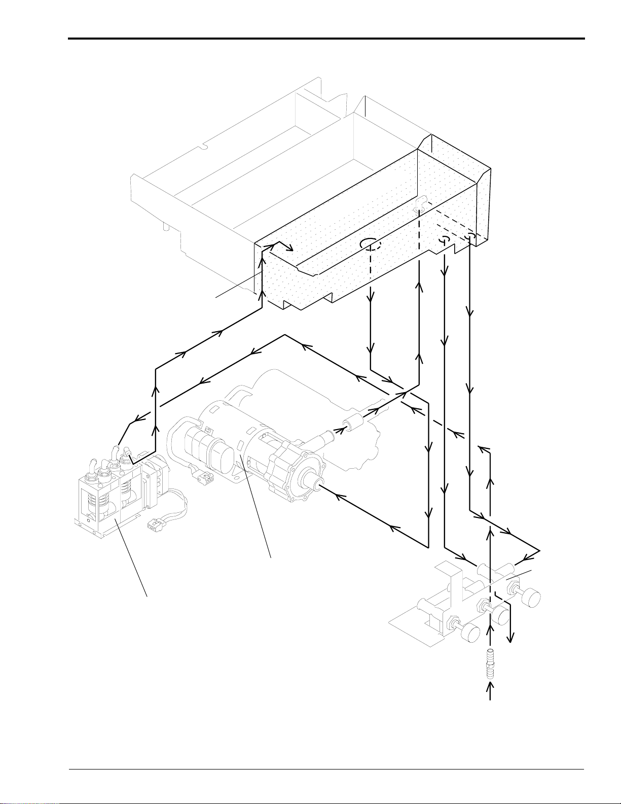
Figure 2 Solution Flow in the DEVELOPER TANK
WASH
FIXER
REPLENISHMENT
into
PROCESSOR
Basic Principles of Film Processing
DEVELOPER
V
E
D
FIX
REPLENISHMENT PUMP
RECIRCULATION PUMP
DRAIN
VALVE
H130_0123ECA
H130_0123EA
981095 – September 1995 9
Page 10

THEORY GUIDE
FIXER SECTION
Components
The FIXER SECTION contains the following components:
• FIXER RACK, which consists of:
– Series of GEARS and ROLLERS
– GUIDE SHOES
• FIXER TANK, which consists of:
– HEAT EXCHANGER - (M43 and M43A Models Only)
• FIXER RECIRCULATION PUMP
• FIXER REPLENISHMENT PUMP
Process
The fixing process consists of a few simple steps.
[1] The film enters the FIXER RACK from the DEVELOPER SECTION through a set of ENTRANCE
ROLLERS.
[2] The FIXER RACK immerses the film in the TANK full of fixer solution for 17 seconds.
[3] The FIXER RECIRCULATION PUMP continually recirculates the fixer solution from the TANK into the
RACK. The pumping action causes the gentle agitation of the fixer solution surrounding the film in the FIXER
RACK.
[4] The film exits the FIXER RACK and enters the WASH SECTION.
[5] The amount of fixer replenishment solution that the replenishment system delivers is based on the area of film
fed.
10 September 1995 – 981095
Page 11
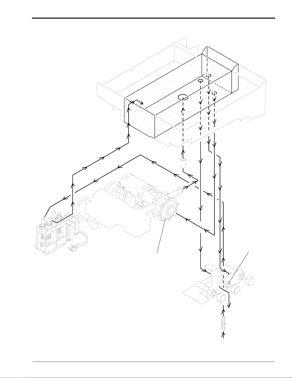
Figure 3 Solution Flow in the FIXER TANK
Basic Principles of Film Processing
WASH
FIXER
DEVELOPER
EV
D
FIX
DRAIN
VALVE
RECIRCULATION
PUMP
H130_0124ECA
H130_0124EA
981095 – September 1995 11
Page 12

THEORY GUIDE
WASH SECTION
Components
The WASH SECTION contains the following components:
• WASH RACK, which consists of:
– set of ENTRANCE ROLLERS
– UPPER WASH TUBE
– LOWER WASH TUBE
– set of EXIT SQUEEGEE ROLLERS
– series of GEARS and ROLLERS
– MANIFOLD
• WATER SOLENOID
• WASH TANK
• WASH PUMP
• DIVERTER VALVE (M43 and M43A Models Only)
Process
The washing process consists of a few simple steps.
[1] The film enters the WASH RACK from the FIXER SECTION through a set of ENTRANCE ROLLERS.
[2] The WASH RECIRCULATION PUMP pumps wash water from the TANK, through the DIVERTER VALVE
(M43 and M43A Only), through the MANIFOLD, and into the LOWER and UPPER WASH TUBES.
[3] The WASH TUBES create a fluid suspension layer through which the film passes. This technique allows for
superior rinsing of the film without needing to immerse the film into the TANK.
[4] The EXIT SQUEEGEE ROLLERS eliminate any excess water from the film before the film enters the DRYER
RACK.
[5] The film exits the WASH RACK and enters setpointthe DRYER SECTION.
The wash stage is critical to the entire process because:
• Washing the film eliminates all residual chemicals and therefore:
– prevents artifacts on the film
– prevents the deterioration of the image over time
12 September 1995 – 981095
Page 13
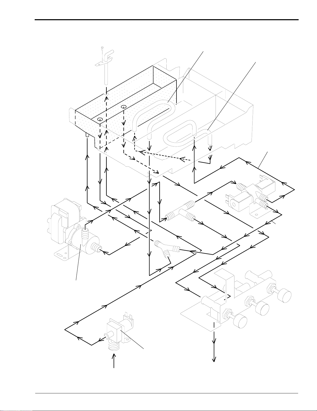
Figure 4 Wash Water Flow in the M43 and M43A PROCESSORS
Basic Principles of Film Processing
WASH
FIXER
HEAT
EXCHANGER
FIXER
DEVELOPER
DEVELOPER
HEAT
EXCHANGER
Path for
Developer
Cooling
Mode
WASH
PUMP
INPUT
WATER
SOLENOID
DRAIN
Path for
Normal
Mode
H130_0121ECA
H130_0121EA
981095 – September 1995 13
Page 14
THEORY GUIDE
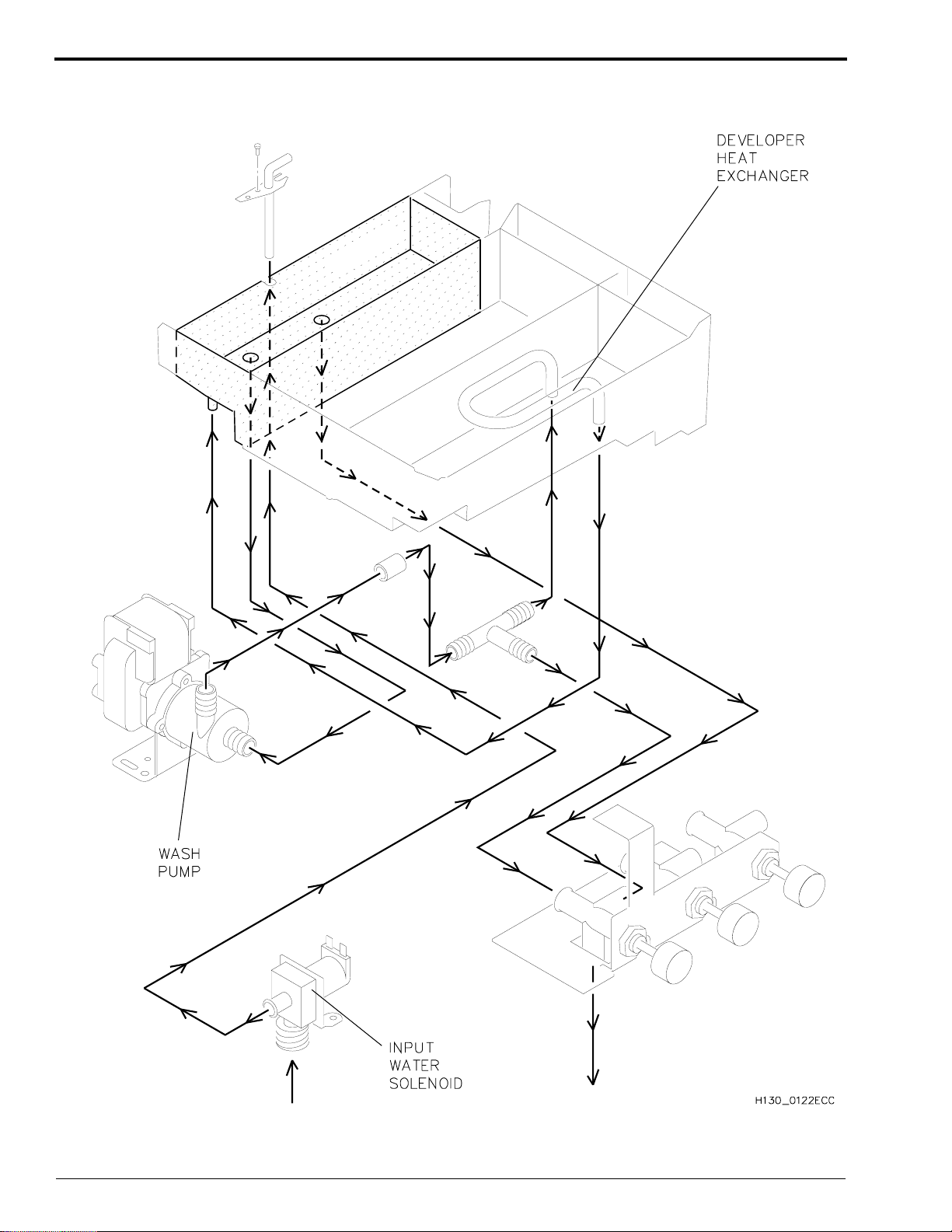
Figure 5 Wash Water Flow in the Clinic 1 PROCESSOR
WASH
FIXER
DEVELOPER
DRAIN
14 September 1995 – 981095
H130_0122EA
Page 15

Basic Principles of Film Processing
DRYER SECTION
Components
The DRYER SECTION contains the following components:
• DRYER RACK, which includes:
– AIR TUBES
– FILM TRANSPORT ROLLERS
• PLENUM, which includes:
– BAFFLE
– HEATER
– AIR VANE SWITCH
– THERMISTOR
• BLOWER
• TEMPERATURE CONTROL POTENTIOMETER
Process
The drying process consists of a few simple steps.
[1] The film enters the DRYER RACK from the WASH SECTION through a set of ENTRANCE ROLLERS.
[2] The film is transported through the RACK by a series of ROLLERS. AIR TUBES create 2 layers of hot air
through which the film passes. The method of drying allows hot air to be circulated across both sides of the
film as the film passes through the ROLLERS, and consequently allows for a more efficient dryer system.
[3] The film exits the DRYER RACK and enters into the RECEIVING BIN.
981095 – September 1995 15
Page 16

THEORY GUIDE
Section 3: Temperature Control
Regulating the Temperature of the Developer Solution
Components
The temperature of the developer solution is regulated by several different components:
• DEVELOPER RECIRCULATION PUMP (B5)
• DEVELOPER THERMISTOR (RT1)
• 100 CIRCUIT BOARD
• WASH RECIRCULATION PUMP (B2)
• SOLID STATE RELAY (U3) controlling DEVELOPER HEATER (HR1)
• SOLID STATE RELAY (U4) controlling WASH RECIRCULATION PUMP (B2)
– B2 recirculates water through a HEAT EXCHANGER in the DEVELOPER TANK
• DIVERTER VALVE ASSEMBLY (M43 and M43A Models Only)
• INCOMING WATER SOLENOID (L1)
• HEAT EXCHANGER in the DEVELOPER TANK
Process
The components listed above regulate and maintain the temperature of the developer solution to within ± 0.3°C
(±0.5°F) of the set-temperature through a series of steps:
Important
The DC INTERLOCK S6 is only found in PROCESSORS that either have a serial number of 350 or higher, or have
Mod 1 installed.
[1] The closing of the TOP COVER actuates the 2 INTERLOCK SWITCHES S5 and S6.
[2] CIRCUIT BREAKER (CB1) provides voltage to the DEVELOPER RECIRCULATION PUMP (B2).
[3] While the developer solution is recirculating, the DEVELOPER THERMISTOR (RT1) monitors the
temperature of the developer solution.
[4] The resistance of the DEVELOPER THERMISTOR (RT1) changes inversely with the temperature of the
developer solution.
[5] The 100 CIRCUIT BOARD reacts to variations in resistance that develop across the DEVELOPER
THERMISTOR (RT1) due to a change in temperature of the developer solution.
[6] The PROCESSOR compares the sensed temperature value to the set-temperature value. The PROCESSOR
maintains the set-temperature by the following series of steps.
(a) If necessary, the PROCESSOR supplies heat by energizing and de-energizing SSR U3 and the
DEVELOPER HEATER (HR1).
(b) If necessary, the PROCESSOR provides cooling by energizing and de-energizing several components:
• SSR U4
• WASH RECIRCULATION PUMP (B2)
• DIVERTER VALVE ASSEMBLY (M43 and M43A Only)
– L2 DEVELOPER COOLING SOLENOID (M43 and M43A Only)
– L3 WASH SOLENOID (M43 and M43A Only)
• INCOMING WATER SOLENOID (L1)
16 September 1995 – 981095
Page 17

Temperature Control
The Developer Heating System
Once the DEVELOPER THERMISTOR (RT1) senses a temperature change, the information is transmitted through
CONNECTOR P/J104 into the MICROPROCESSOR located on the 100 CIRCUIT BOARD. The
MICROPROCESSOR then determines when it needs to actuate the SOLID STATE RELAY (U3). Once actuated,
the SOLID STATE RELAY (U3) then applies line voltage to energize the DEVELOPER HEATER (R1). The
MICROPROCESSOR uses a proportional control algorithm to determine when to energize the components. The
algorithm determines the correct duty cycle for the DEVELOPER HEATER depending on how close the temperature
reading is to the setpoint temperature. The table below indicates the relationship between duty cycle and developer
temperature.
Table 3 DEVELOPER HEATER Duty Cycles
Current Developer Temperature
Duty Cycle
100% > 1.0° below setpoint temperature
75% <= 1.0°, > 0.7° below setpoint temperature
60% <= 0.7°, > 0.5° below setpoint temperature
40% <= 0.5°, > 0.3° below setpoint temperature
20% <= 0.3°, > 0.2° below setpoint temperature
0% <= 0.2° below setpoint temperature
Measured in °Fahrenheit*
* To convert degrees Fahrenheit to degrees Celsius, subtract 32 from the Fahrenheit temperature and divide the
resulting temperature by 1.8.
Kodak X-Omat Clinic 1 PROCESSOR Only:
The PROCESSOR energizes the DEVELOPER HEATER 100% to offset the cooling effect of the WASH PUMP
only when both conditions below exist:
1. The PROCESSOR energizes the WASH PUMP because an operator is feeding film.
2. The developer temperature is below the setpoint temperature.
Developer Temperature Control
Measuring the Temperature of the Developer Solution
Kodak X-Omat M43 and M43A PROCESSORS have a THERMISTOR, which measures the temperature of the
developer solution. The PROCESSOR averages 10 THERMISTOR readings in order to minimize the effect of
instantaneous changes of temperature at the THERMISTOR. The DEVELOPER TEMPERATURE DISPLAY,
located on the FRONT PANEL of the PROCESSOR, displays the temperature obtained from the averaging process,
and updates the DISPLAY every 2 seconds.
Controlling the Temperature of the Developer Solution (Heating Only)
The temperature control subsystem is responsible for maintaining the temperature of the developer solution to within
0.3°C (0.5°F) above or below the setpoint temperature under all operating conditions of the PROCESSOR.
The setpoint temperature for the developer solution may be set for any temperature between 32 − 39°C
(90 − 102.5°F). Only a qualified service provider should set or change the setpoint temperature by rotating
POTENTIOMETER (R25) on the 100 CIRCUIT BOARD. Normally, the service person sets up the PROCESSOR
to obtain optimum results for use with Kodak film and chemicals. The optimum setpoint temperature when using
Kodak film and chemicals is 33.9°C (93°F).
Calibrating the DEVELOPER TEMPERATURE DISPLAY
The DEVELOPER TEMPERATURE DISPLAY can be calibrated by rotating POTENTIOMETER (R42). Only a
qualified service provider should calibrate the DEVELOPER TEMPERATURE DISPLAY.
981095 – September 1995 17
Page 18

THEORY GUIDE
Figure 6 Control System for Developer Temperature
RT1
DEVELOPER
THERMISTOR
10 K
C@ 25
CB1
L1
R25
R42
+5 V DC
+5 V Return
-15 V DC
+15 V DC
100 PCB
DEVELOPER
TEMPERATURE
ADJUST
DEVELOPER DISPLAY
CALIBRATION
(M43,M43A)
DEVELOPER
TEMPERATURE DISPLAY
M43 AND M43A ONLY
DIVERTER VALVE ASSEMBLY
SOLENOIDS L2 AND L3
M43 AND M43A ONLY
WATER INPUT
SOLENOID
L1
L2
or N
DEVELOPER
RECIRCULATION
PUMP
B5
SSR
U3
A1
DC POWER
SUPPLY
DEVELOPER
HEATER
R1
DEVELOPER TEMPERATURE CONTROL
M43, M43A AND CLINIC 1 PROCESSORS
AC DC
SSR
U4
WASH RECIRCULATION
PUMP MOTOR
B3
H130_0003DC_
18 September 1995 – 981095
Page 19

Temperature Control
Operation of the Cooling System in the Kodak X-Omat Clinic 1 PROCESSOR Only:
During Standard Film Feeding:
Approximately 45 seconds after an operator feeds a sheet of film into the PROCESSOR, the WASH
RECIRCULATION PUMP actuates to circulate wash water through the HEAT EXCHANGER in the bottom of the
DEVELOPER TANK. Because the wash water is cold, the flow of the water through the HEAT EXCHANGER
tends to cool the temperature of the developer solution. If necessary to partially offset the decrease in temperature
of the developer solution, the DEVELOPER HEATER may energize. The cold wash water that is circulated through
the HEAT EXCHANGER in the DEVELOPER TANK eventually returns to the WASH TANK through the WASH
TUBES in the WASH RACK, thus completing the cycle. Because this cooling process takes time to work, you
should not feed more than 5 sheets of film consecutively, or else a wait condition may result.
When the Developer Temperature Rises Above the setpoint Temperature:
If the temperature of the developer solution increases and reaches 0.1°C (0.2°F) above the setpoint temperature, the
WASH RECIRCULATION PUMP energizes. The WASH RECIRCULATION PUMP circulates wash water from
the WASH TANK through the HEAT EXCHANGER in the DEVELOPER TANK and back into the WASH TANK.
This action helps to cool the developer solution.
When Additional Cooling is Required From the WATER INPUT SOLENOID in Low Water Usage Mode:
If however, the wash water becomes too warm to provide sufficient cooling for the developer solution, and the
temperature of the developer solution reaches 0.15°C (0.3°F) above the setpoint temperature, the WATER INPUT
SOLENOID energizes. The WATER INPUT SOLENOID provides cooler incoming water that reduces the
temperature of the water in the WASH TANK. The WATER INPUT SOLENOID remains energized and the cooling
process continues until the temperature of the developer solution decreases to 0.1°C (0.2°F) above the setpoint
temperature. Once the temperature of the developer solution decreases to just 0.1°C (0.2°F) above the setpoint
temperature, the WATER INPUT SOLENOID de-energizes, but the WASH PUMP remains energized circulating
wash water through the HEAT EXCHANGER until the temperature of the developer solution decreases to setpoint
temperature.
In Continuous Water Usage Mode, the WATER INPUT SOLENOID remains energized continuously after warm-up.
981095 – September 1995 19
Page 20

THEORY GUIDE
Operation of the Cooling System in the Kodak X-Omat M43 and M43A PROCESSORS
Only:
Because the M43 and M43A PROCESSORS contain a DIVERTER VALVE that the Clinic 1 PROCESSOR does
not have, the cooling system of the M43 and M43A PROCESSORS works differently from that of the Clinic 1
PROCESSOR.
During Standard Film Feeding
Approximately 45 seconds after an operator feeds a sheet of film into the PROCESSOR, the WASH
RECIRCULATION PUMP actuates to circulate wash water. Up to this point, the M43 and M43A PROCESSORS
operate similarly to the Clinic 1 PROCESSOR. In the Clinic 1 PROCESSOR, the WASH RECIRCULATION
PUMP pumps the cool wash water into the HEAT EXCHANGER in the DEVELOPER TANK. In the M43 and
M43A PROCESSORS, the wash water may or may not be pumped into the HEAT EXCHANGER depending upon
the temperature of the developer solution. If the temperature of the developer solution is within the acceptable range,
then the DIVERTER VALVE remains closed and the wash water is pumped only through the WASH SECTION of
the PROCESSOR. By not pumping the cool wash water through the HEAT EXCHANGER in the DEVELOPER
TANK, the PROCESSOR helps to maintain the setpoint temperature of the developer solution.
When the Developer Temperature Rises Above the setpoint Temperature:
If however the temperature of the developer solution reaches 0.1°C (0.2°F) above the setpoint temperature, the
PROCESSOR switches the DIVERTER VALVE to its cooling position. In this case, the WASH
RECIRCULATION PUMP circulates the cool wash water through the HEAT EXCHANGER in the DEVELOPER
TANK and then through the WASH SECTION of the PROCESSOR. The circulation of the cool wash water through
the HEAT EXCHANGER in the developer tank thereby helps to cool the developer solution.
When Additional Cooling is Required From the WATER INPUT SOLENOID in Low Water Usage Mode:
If however, the wash water becomes too warm to provide sufficient cooling for the developer solution, and the
temperature of the developer solution reaches 0.15°C (0.3°F) above the setpoint temperature, the WATER INPUT
SOLENOID energizes. The WATER INPUT SOLENOID provides cooler incoming water that reduces the
temperature of the water in the WASH TANK. The WATER INPUT SOLENOID remains energized and the cooling
process continues until the temperature of the developer solution decreases to 0.1°C (0.2°F) above the setpoint
temperature. Once the temperature of the developer solution decreases to just 0.1°C (0.2°F) above the setpoint
temperature, the WATER INPUT SOLENOID de-energizes, but the WASH PUMP remains energized circulating
wash water through the HEAT EXCHANGER until the temperature of the developer solution decreases to setpoint
temperature.
Operation of the Water Usage Mode
The PROCESSOR is factory set for Continuous Water Usage Mode. In this mode, water runs at one litre per minute.
This allows fresh water to circulate through the PROCESSOR and prevent biological growth. If biological growth is
not a concern, the PROCESSOR may be set to Low Water Usage Mode.
In Continuous Water Usage Mode, the WATER INPUT SOLENOID remains energized continuously after warm-up.
The WASH WATER DRAIN VALVE has an orifice that allows continuous draining of the WASH TANKS.
20 September 1995 – 981095
Page 21

Figure 7 Control Systems for Cooling the Developer Solution
RT1
DEVELOPER THERMISTOR
100 BOARD
Temperature Control
FILM SENSOR
U7
-
L1
L2
or N
CB1
10 K
@ 25 C
F2
+5 V Return
+5 V DC
DC POWER
SUPPLY
FILM SENSOR
U8
FILM SENSOR
U9
WATER INPUT
SOLENOID L1
DIVERTER VALVE
WASH SOLENOID L3
M43 & M43A ONLY
-15 V DC
+15 V DC
SSR
U4
A1
B2
DIVERTER VALVE
COOLING SOLENOID L2
M43 & M43A ONLY
WASH
RECIRCULATION
PUMP
CENTER
+
WASH WATER AND DEVELOPER COOLING CONTROL
DCAC
H130_0000DC_
981095 – September 1995 21
Page 22

THEORY GUIDE
Regulating the Temperature of the Fixer Solution
In the Kodak X-Omat M43 and M43A PROCESSORS Only:
The M43 and M43A PROCESSORS regulate the temperature of the fixer solution by pumping wash water through
the HEAT EXCHANGER in the bottom of the FIXER TANK. The wash water either absorbs or gives off heat
depending upon its temperature relative to the temperature of the fixer solution. The transfer of heat between the
wash water in the HEAT EXCHANGER and the fixer solution eventually cools or heats the fixer solution.
Unlike the DEVELOPER TANK, the FIXER TANK does not contain a HEATER or a THERMISTOR. Because the
temperature of the fixer solution is regulated through heat transfer and not regulated electronically, the HEATER and
THERMISTOR are not needed.
In the Kodak X-Omat Clinic 1 PROCESSOR Only:
Unlike the M43 and M43A PROCESSORS, the Clinic 1 PROCESSOR does not regulate the temperature of the fixer
solution. Therefore, the Clinic 1 PROCESSOR does not have a HEAT EXCHANGER in the FIXER TANK. The
temperature of the fixer solution depends primarily on the internal temperature of the PROCESSOR, which is
regulated by the DRYER temperature setting. However, the fixer temperature can also be affected by the ambient
temperature and room conditions. If the ambient temperature and humidity are not within the specifications outlined
in the Site Specifications, Publication Number 981087, correct “fixing” of the films cannot be ensured.
22 September 1995 – 981095
Page 23

Temperature Control
Regulating the Temperature of the DRYER
Adjusting the setpoint Temperature of the DRYER
The operator can select and adjust the setpoint temperature of the DRYER simply by rotating the DRYER
TEMPERATURE CONTROL KNOB located on the front DISPLAY PANEL of the PROCESSOR. By rotating the
DRYER TEMPERATURE CONTROL KNOB, the operator is actually rotating the DRYER HEATER
POTENTIOMETER (R3). The KNOB provides the operator with 11 detent positions to choose from. The detent
positions correspond to the setpoint temperatures outlined in the table below.
Table 4 DRYER setpoint Temperatures for the M43, M43A, and Clinic 1 PROCESSORS
Detent
Position A/D Range Celsius Fahrenheit
0 0 - 11 32° 90°
1 12 - 37 34.4° 94°
2 38 - 63 36.7° 98°
3 64 - 88 38.9° 102°
4 89 - 113 41.4° 106°
5 114 - 139 43.1° 110°
6 140 - 165 45.6° 114°
7 166 - 191 48.0° 118°
8 192 - 216 50.0° 122°
9 217 - 242 52.2° 126°
10 243 - 255 54.2° 130°
Once the operator has selected a setpoint temperature for the DRYER, the DRYER temperature control subsystem
is responsible for maintaining the temperature of the DRYER to within approximately 4°C (7°F) above or below the
setpoint temperature.
Components
The DRYER temperature control subsystem includes several components:
• DRYER THERMISTOR (RT2)
• 100 CIRCUIT BOARD
• SOLID STATE RELAY (U6) controlling DRYER BLOWER (B1) and DRIVE MOTOR (B4)
• DRYER AIR VANE SWITCH (S4)
• DRYER HEATER POTENTIOMETER (R3)
• SOLID STATE RELAY (U1) controlling DRYER HEATER (HR2)
981095 – September 1995 23
Page 24

THEORY GUIDE
Process
The components listed regulate and maintain the temperature of the DRYER through a series of steps:
[1] The 100 CIRCUIT BOARD senses air temperature changes in the DRYER when resistance variations develop
across DRYER THERMISTOR (RT2) due to temperature changes in the DRYER.
[2] RT2 varies inversely (decreasing in resistance) as DRYER air temperature increases.
[3] The 100 BOARD compares the DRYER setpoint temperature (R3) to the actual temperature (RT2) of the air
in the PLENUM.
[4] The 100 BOARD energizes SOLID STATE RELAY (U1) to control power and duty cycle to DRYER
HEATER (HR2).
[5] DRYER AIR VANE SWITCH (S4) monitors the BLOWER status and informs the 100 BOARD when it is safe
to apply power to DRYER HEATER (HR2).
Figure 8 DRYER Circuit for the M43A and Clinic 1 PROCESSORS
In M43 PROCESSORS, the HEATER COILS are Wired in Series
RT2
DRYER THERMISTOR
100 BOARD
L1
L2
or N
CB1
10 K
@ 25 C
R3
DRYER
HEATER
POTENTIOMETER
10 K
SSR
U6
S4
AIR VANE
SWITCH
F2
SSR
U1
DRYERDRIVE
BLOWERMOTOR
B3B3
MOTOR
DRYER
HEATER
+5 V DC
+5 V Return
-15 V DC
+15 V DC
A1
DC POWER
SUPPLY
DRYER TEMPERATURE CONTROL
AC DC
H130_0002DC_
24 September 1995 – 981095
Page 25

Temperature Control
DRYER Operation During PROCESSOR Start-Up
When the PROCESSOR is first energized, the DRYER HEATER energizes to 100% of its capacity until the
temperature of the DRYER reaches 4°C (7°F) above the setpoint temperature. If the temperature of the DRYER has
not reached at least 3°C (5°F) below the setpoint temperature within 45 minutes after the operator energized or reset
the PROCESSOR, the PROCESSOR indicates an error condition. The PROCESSOR may display either a DRYER
Under Range Error (E10) or a DRYER Under Temperature Warning (E13), depending upon how far the DRYER
temperature is below the setpoint temperature.
DRYER Operation During the Processing of Films
Located in the DRYER SECTION of the PROCESSOR, is a DRYER HEATER. The 100 CIRCUIT BOARD
controls the DRYER HEATER by sending an actuation command to SSR U1. SSR U1 then controls the current
necessary to energize the DRYER HEATER.
The PROCESSOR energizes the DRYER HEATER to 100% of its capacity in 2 operating conditions:
1. The temperature of the DRYER is more than 2.3°C (4°F) below the setpoint temperature, and the DRYER
TEMPERATURE CONTROL KNOB is set between 1 and 8.
2. The DRYER TEMPERATURE CONTROL KNOB is set at 9 or 10.
The DRYER HEATER remains energized at 100% of its capacity until one of the following conditions exists:
1. The temperature of the DRYER reaches 4°C (7°F) above the setpoint temperature with the DRYER
TEMPERATURE CONTROL KNOB set between 1 and 8.
2. The 2 Minute Film Clear TIMER expires and the DRYER TEMPERATURE CONTROL KNOB is set
at 9 or 10.
3. The temperature of the DRYER reaches 66°C (150°F).
4. The temperature of the developer reaches more than 3°C (5°F) above the setpoint temperature.
The DRYER HEATER energizes again if, during normal operation, the temperature of the DRYER falls to between
2.3 and 4°C (4 and 7°F) below the setpoint temperature. The DRYER HEATER remains energized until the
temperature of the DRYER is again within 2.3°C (4°F) of the setpoint temperature.
The PROCESSOR energizes the DRYER HEATER to only 60% of its capacity if the temperature of the DRYER
reaches 4°C (7°F) above the setpoint temperature and the DRYER TEMPERATURE CONTROL KNOB is set
between 1 and 8.
981095 – September 1995 25
Page 26

THEORY GUIDE
Explanation of Flowchart for DRYER Operation During the Feeding of Film
[1] The MICROPROCESSOR energizes the DRYER BLOWER.
[2] The MICROPROCESSOR sets a 2-minute DELAY TIMER and checks the status of the AIR VANE SWITCH.
(a) If the AIR VANE SWITCH is open and the 2-minute DELAY TIMER has expired, then Error 03 - Air
Vane Switch Error is displayed on the DISPLAY PANEL.
(b) If the AIR VANE SWITCH is closed, then the MICROPROCESSOR completes the following actions:
• energizes the DRYER HEATER
• checks the status of the AIR VANE SWITCH
• reads the DRYER HEATER POTENTIOMETER (R3) to determine the setpoint temperature of the
DRYER
• reads the THERMISTOR to determine the actual temperature of the DRYER
• The DRYER at this point, operates normally at 100% of its capacity until the temperature of the
DRYER reaches 4°C (7°F) above the setpoint temperature.
• If the 2-minute FILM CLEAR TIMER has expired and the temperature of the DRYER has increased
to 4°C (7°F) above the setpoint temperature, provided that no film has been sensed, then the
MICROPROCESSOR completes the following actions:
– de-energizes the DRYER HEATER
– de-energizes the DRYER BLOWER
– sets the 5-minute STANDBY TIMER
26 September 1995 – 981095
Page 27

Figure 9 DRYER Control Flowchart for PROCESSOR During the Processing of Films
Temperature Control
Exit Standby Mode,
Lead Edge of Film
Detected
N
Is Temperature
> 150 ?
Y
Dryer potentiometer
Position = 9 or 10 ?
Y
Energize
Heater 100%
Airflow Still
Present?
Y
Read Dryer
Potentiometer
Read
Thermistor
Y
N
N
Air Flow
Present?
N
2 Minute
Delay Timer
Expire?
Y
Air Vane
Switch Error
Displayed
Is Temperature > =
setpoint + 7 ?
Y
N
N
Error Mode
**
Is Temperature
Less Than
Setpoint - 4 ?
Energize
Blower
Start 2 Minute
Delay Timer
Error mode will de-energize
Dryer Heater.
**
Y
Energize
Heater 100%
N
Is Temperature < =
Setpoint + 7 ?
Y
Energize
Heater 100%
De-energize Heater
De-energize Blower
Standby Mode
N
Energize
Heater 60%
N
Y N
2 Minute
Film Clear Timer
**
Expired
Y
Is Temperature
> = Setpoint ?
Y
Airflow Still
Present?
N
Energize
Heater 60%
2 Minute Film Clear Timer is started
when the trail edge of film is detected.
Developer Over
Temperature ?
N
Energize
Heater 100%
Energize
Heater 60%
**
Set Air Vane
Switch Error
Y
*
Film Clear Timer
*
De-energize
Heater
Error Mode
2 Minute
Expired
Y
Error mode will de-energize
Dryer Heater.
*
Read
Thermistor
Read Dryer
Potentiometer
Y
Airflow Still
Present?
H130_9003EC
NN
981095 – September 1995 27
Page 28

THEORY GUIDE
DRYER Operation While the PROCESSOR is in Standby Mode
Both the DRYER HEATER and DRYER BLOWER energize on and off while the PROCESSOR is in Standby
Mode. The DRYER HEATER and DRYER BLOWER remain “off” for 5 minutes. However the length of time that
the DRYER HEATER and DRYER BLOWER remain “on” may change. The components can remain “on”
anywhere from 30 seconds to as long as is required for the DRYER to reach 4°C (7°F) above the setpoint temperature.
For example, if the input voltage to the PROCESSOR is low, the “ON” cycles may become longer.
DRYER Temperature Control Algorithm to Assist With the Cooling of the Developer
Solution
When the temperature of the developer solution reaches 0.3°C (0.5°F) over the setpoint temperature, the DRYER
BLOWER energizes to help remove hot air and draw in cooler air in order to assist with the cooling of the developer
solution. The DRYER BLOWER remains energized until the temperature of the developer is within 0.1°C (0.2°F)
of its setpoint temperature. Once the developer is within 0.1°C (0.2°F) of its setpoint temperature, the DRYER
HEATER energizes and remains energized until the temperature of the DRYER reaches the setpoint temperature.
Once the DRYER is at setpoint, the entire DRYER system enters the Standby Mode.
DRYER Operation During the Cooling of the Developer Solution
The DRYER HEATER de-energizes, and the DRYER BLOWER remains energized in order to vent hot air, thereby
helping to cool the developer solution when the following conditions exist:
• the FILM SENSORS do not detect film
• the temperature of the developer solution is more than 0.3°C (0.5°F) above the developer setpoint temperature
and Service Error 08 - Developer Over Temperature Range is displayed on the DISPLAY PANEL of the
PROCESSOR
If the conditions listed above exist, then the DRYER system initiates the following actions:
• the DRYER HEATER is de-energized if it is currently energized
• the DRYER HEATER remains de-energized until the temperature of the developer solution is 0.1°C (0.2°F)
above the developer setpoint temperature
• the DRYER HEATER is then energized until the air temperature in the DRYER reaches the setpoint temperature
– at this point, the DRYER enters Standby Mode
28 September 1995 – 981095
Page 29

Temperature Control
Explanation of Flowchart for DRYER Operation During Standby Mode
Every 5 minutes the PROCESSOR completes the standby cycle and exits Standby Mode for a minimum of
30 seconds. The MICROPROCESSOR first checks the status of the AIR VANE SWITCH.
[1] If the AIR VANE SWITCH is closed, the MICROPROCESSOR displays Error 03 - Air Vane Switch Error on
the DISPLAY PANEL of the PROCESSOR.
[2] If the AIR VANE SWITCH is open, the MICROPROCESSOR completes the following actions:
• energizes the DRYER BLOWER
• starts the 2-minute DELAY TIMER
• checks the status of the AIR VANE SWITCH continually until air flow is detected
(a) If the 2-minute DELAY TIMER has expired and no air flow has been detected, the MICROPROCESSOR
displays Service Error 02 - Loss of Air Flow Error on the DISPLAY PANEL of the PROCESSOR.
(b) If air flow is detected, the MICROPROCESSOR starts a 30-second TIMER and completes the following
actions repeatedly for as long as air flow is detected:
• checks for the presence of film
• reads the DRYER HEATER POTENTIOMETER (R3) to determine the setpoint temperature of the
DRYER
• reads the THERMISTOR to determine the actual temperature of the DRYER
• checks whether the temperature of the DRYER is more than 4°C (7°F) above the setpoint temperature
If the DRYER temperature is less than 4°C (7°F) above setpoint, the MICROPROCESSOR checks
whether the temperature of the developer solution is over the setpoint temperature.
• If the developer is over temperature, the DRYER HEATER de-energizes but the DRYER BLOWER
remains energized to assist with the cooling of the developer solution.
• If the developer is not over temperature, the DRYER HEATER energizes to 100% of its capacity until
the temperature of the DRYER reaches 4°C (7°F) above the setpoint temperature.
• Once the DRYER temperature reaches 4°C (7°F) above setpoint, the MICROPROCESSOR
completes the following actions:
– de-energizes the DRYER HEATER
– de-energizes the DRYER BLOWER, provided that the 30-second TIMER has expired
– starts the 5 minute Standby TIMER, provided that the 30-second TIMER has expired
• If the operator feeds film during this cycle, the PROCESSOR exits the Standby Mode and enters the
Film Run Mode.
• If the operator increases the setting of the DRYER TEMPERATURE CONTROL KNOB, the
PROCESSOR exits the Standby Mode in order to increase the DRYER temperature and cycles
through the steps outlined above.
981095 – September 1995 29
Page 30

THEORY GUIDE
Figure 10 DRYER Control Flowchart for PROCESSOR When Cycling Through Standby Mode
Energize
Processor
Start 30 sec.
Timer
Y
Energize
Blower
Start 2 Minute
Delay Timer
Air Flow
Present?
N
2 Minute
Delay Timer
Expire?
Y
N
Air Flow Still
Present?
Y
N
N
Air Vane
Switch
Stuck?
Y
Air Vane
Switch Error
Displayed
Error Mode
Set Loss of Air Flow
*
Error
Error mode will
*
turn OFF the
Dryer Heater.
Dryer Film
Run Mode
Y
Y
Y
5 Minute
Standby Timer
Expired?
N
Setpoint
Increased?
Read Dryer
Potentiometer
N
Film
Present?
Start 5 Minute
Standby Timer
De-energize
Blower
N
Energize
Heater
100%
N
De-energize
Y
Developer
Over
Temperature?
Heater
Film
Present?
N
Read Dryer
Potentiometer
Read
Thermistor
Y
Temperature
Below
Setpoint +7
Degrees F
N
De-energize
Heater
Y
Dryer Film
Run Mode
N
30 sec
Timer
Expire?
Y
H130_9004EC
30 September 1995 – 981095
Page 31

Control Systems
Section 4: Control Systems
AC and DC INTERLOCK SWITCHES
Note
The DC INTERLOCK SWITCH S6 is only found in PROCESSORS that either have a serial number of 350 or
higher, or have Mod 1 installed. PROCESSORS having a serial number below 350 or without Mod 1 installed have
a single SWITCH that incorporates both the AC and DC interlocks.
The INTERLOCK SWITCH(ES) serve(s) as safety feature(s) for the operator. The INTERLOCK SWITCH(ES)
prevent(s) the PROCESSOR from operating without the TOP COVER installed. Therefore, the operator cannot feed
films without the TOP COVER installed. Having the TOP COVER installed when the operator feeds films protects
the operator from possible harm from contact with moving parts.
The AC INTERLOCK SWITCH S5 is located on the drive side of the PROCESSOR near the DRYER SECTION.
The DC INTERLOCK SWITCH S6 is located on the non-drive side of the DRYER PLENUM and is actuated by a
MAGNET inside the TOP COVER.
MAIN CIRCUIT BREAKER CB1
The MAIN CIRCUIT BREAKER CB1 is located on the DISPLAY PANEL on the front of the PROCESSOR.
Moving the MAIN CIRCUIT BREAKER CB1 to the “ON” position, allows you to energize the PROCESSOR. The
PROCESSOR contains a built-in safety feature that will not allow the PROCESSOR to energize if the TOP COVER
is not installed correctly onto the PROCESSOR.
Once you actuate the MAIN CIRCUIT BREAKER CB1, each separate system of the PROCESSOR energizes.
• The DRIVE MOTOR rotates the MAIN DRIVE SHAFT and the DRIVE ROLLERS.
• The DEVELOPER and FIXER RECIRCULATION PUMPS recirculate the processing solutions in the
DEVELOPER and FIXER TANKS.
• the DC POWER SUPPLY (A1) and the low voltage TRANSFORMER (T1) provide power to the 100 CIRCUIT
BOARD.
100 CIRCUIT BOARD
The 100 CIRCUIT BOARD contains a MICROPROCESSOR, which monitors and controls the PROCESSOR as
shown.
Table 5 Monitor and Control Functions of the MICROPROCESSOR
Components Monitored Components Controlled
SENSORS STATUS INDICATORS
SWITCHES SOLID STATE RELAYS
981095 – September 1995 31
Page 32

THEORY GUIDE
System Initialization
The software initialization procedure occurs any time you:
• energize the PROCESSOR
• reset the PROCESSOR by:
– placing the TOP COVER on the PROCESSOR
– exiting from the Diagnostic Mode
The PROCESSOR performs the initialization routine using limited hardware on the 100 CIRCUIT BOARD.
The hardware completes the following basic self-checks on the 100 CIRCUIT BOARD to ensure that the
MICROPROCESSOR can execute its resident programs.
• RAM test
• PROM checksum test
• I/O PORT check
Sequence of Events after the Completion of the Initialization Routine
Once the 100 CIRCUIT BOARD completes these self-checks successfully, the PROCESSOR performs the actions
listed below:
• beeps 3 times
• energizes the WATER INPUT SOLENOID to fill the WASH TANK
• illuminates the WAIT INDICATOR
• checks the AIR VANE SWITCH for the absence of air flow
– if it detects air flow, it indicates an air flow error
– if it does not detect air flow, it energizes the DRYER BLOWER and DRIVE MOTOR
• checks the AIR VANE SWITCH again, for the presence of air flow
• energizes the DRYER HEATER and the BLOWER to achieve the correct operating conditions
• energizes the DEVELOPER HEATER
• energizes the DEVELOPER RECIRCULATION PUMP
• energizes the FIXER RECIRCULATION PUMP
• energizes the WASH RECIRCULATION PUMP
Note
If the operator energizes the PROCESSOR without the TOP COVER installed, the PROCESSOR beeps 3 times and
enters Replenishment Calibration Mode.
32 September 1995 – 981095
Page 33

Control Systems
Standby Mode
The PROCESSOR enters the Standby Mode when either of the following conditions exists:
1. the temperature of the DRYER reaches 2.5°C (7°F) above its setpoint temperature
2. approximately 2 minutes after the FILM SENSORS detect the trailing edge of a sheet of film on the FEED TRAY
unless the operator feeds a second sheet of film
While in the Standby Mode, the PROCESSOR de-energizes certain components or operates them intermittently in
order to conserve energy and wear on parts:
• de-energizes the WASH RECIRCULATION PUMP, unless the PUMP is needed for cooling
• maintains developer temperature at its setpoint temperature
• de-energizes the DRYER HEATER, DRYER BLOWER and the MAIN DRIVE MOTOR
– every 5 minutes, the PROCESSOR energizes the DRYER BLOWER, DRYER HEATER and MAIN DRIVE
MOTOR for a minimum of 30 seconds or until the temperature of the DRYER reaches 2.5°C (7°F) above its
setpoint temperature
The PROCESSOR, even though in Standby Mode, must occasionally energize the WASH RECIRCULATION
PUMP and the WATER INPUT SOLENOID (L1) to cool the developer solution (intermittently) if the temperature
of the developer solution is 0.1°C (0.2°F) above the setpoint temperature.
Once the FILM SENSORS detect a film on the FEED TRAY, the PROCESSOR automatically exits the Standby
Mode and begins processing films.
Continuous Mode
A qualified service provider can configure the PROCESSOR to operate in the Continuous Mode. The Continuous
Mode feature can be selected to help eliminate ROLLER artifacts from appearing on films. The Continuous Mode
should be selected for sites with extreme ambient and operating conditions. See the Site Specifications, Publication
Number 981087, for the recommended ambient conditions. The Continuous Mode can also be selected when
diagnosing errors with the PROCESSOR. All components of the MAIN DRIVE, FILM TRANSPORT, and DRYER
systems remain energized continuously for as long as the PROCESSOR is in the Continuous Mode.
981095 – September 1995 33
Page 34

THEORY GUIDE
MAIN DRIVE SYSTEM
Overview
Once the FILM SENSORS detect film, the PROCESSOR exits the Standby Mode and enters the Operating Mode.
When the PROCESSOR enters the Operating Mode, the MAIN DRIVE system energizes and is able to transport
film. If you operate the PROCESSOR in the Continuous Mode, the MAIN DRIVE system and all other systems
remain operational at all times. Continuous operation of the PROCESSOR can lead to wear on all the parts.
Sequence of Events for the Operating Mode
[1] When the PROCESSOR enters the Operating Mode, a series of actions occurs:
(a) The MAIN DRIVE MOTOR (B4) activates.
(b) The DRYER BLOWER (B1) activates.
(c) The DRYER HEATER (HR2) energizes.
(d) The WASH RECIRCULATION PUMP (B2) energizes, providing water to the WASH RACK.
[2] While the PROCESSOR is in the Operating Mode, the following series of actions occurs:
(a) The MAIN DRIVE MOTOR (B4) provides rotational energy for the DRIVE system, which is used to
transport film.
Note
The MAIN DRIVE MOTOR for the M43A and Clinic 1 PROCESSORS is a 115 V AC 50/60 Hz MOTOR. The
MAIN DRIVE MOTOR for the M43 PROCESSOR is a 230 V AC 50/60 Hz motor. The MAIN DRIVE MOTOR
has an internal GEAR reduction unit to decrease its RPM range (250 RPM on 50 hertz power and 300 RPM range at
60 hertz). An additional SPROCKET equalizes SHAFT rotation so that the MOTOR transports the film at
1.016 cm/sec (0.4 in./sec). In 1 minute the film travels 60.96 cm (24 in.).
(b) The MAIN DRIVE MOTOR rotates the MAIN DRIVE SHAFT with a DRIVE CHAIN.
(c) A series of WORMS located on the MAIN DRIVE SHAFT drives the DRIVE ROLLERS in the
DEVELOPER RACK, FIXER RACK, and WASH RACK.
(d) A GEAR on the DRIVE ROLLER of the WASH RACK drives the ROLLERS in the DRYER RACK.
(e) The PROCESSOR automatically de-energizes the MAIN DRIVE MOTOR while the PROCESSOR is in
the Standby Mode.
34 September 1995 – 981095
Page 35

Figure 11 The MAIN DRIVE System
60 Hz SPROCKET
16-TOOTH
Control Systems
WASH/DRYER
DRIVE GEAR
FIXER
DRIVE
GEAR
50 Hz SPROCKET
20-TOOTH
DRIVE
CHAIN
MAIN DRIVE
MOTOR
MAIN DRIVE
SHAFT
DEVELOPER DRIVE
GEAR
WORM
(1 of 5)
H130_0167HCC
H130_0167HA
Detecting Film
Overview
The operator should feed a sheet of film along the recommended left edge of the FEED TRAY and into the set of
ENTRANCE ROLLERS. The M43 and M43A PROCESSORS use 3 FILM SENSORS to determine the area of the
sheet of film being fed. The Clinic 1 PROCESSOR uses the same 3 FILM SENSORS, but in the Clinic 1
PROCESSOR the FILM SENSORS determine the length of the film, not the area of the film. The FILM SENSORS
must approximate the film area or length in order to determine the amount of replenishment solution needed to
maintain sensitometric control. The FILM SENSORS use LIGHT EMITTING DIODE (LED) technology to emit
infrared (IR) light energy. The FILM SENSORS pulse the IR light they produce to prevent film exposure. The FILM
SENSORS detect the leading edge of a sheet of film when the film reflects the IR light to a light sensitive receptor
built into the SENSOR. The FILM SENSORS detect the trailing edge of the film when the film no longer reflects
the IR light.
The 3 FILM SENSORS are in 3 different locations on the FEED TRAY:
(RIGHT) FILM SENSOR (U7) - 10.8 cm (4.3 in.) from the left edge of the FEED TRAY
(MIDDLE) FILM SENSOR (U8) - 26.0 cm (10.3 in.) from the left edge of the FEED TRAY
(LEFT) FILM SENSOR (U9) - 40.0 cm (15.8 in.) from the left edge of the FEED TRAY
Note
If the FILM SENSORS detect a film longer than 1.5 m (5 ft), the PROCESSOR indicates an error condition.
981095 – September 1995 35
Page 36

THEORY GUIDE
Film Approximation for the Kodak X-Omat Clinic 1 PROCESSOR Only:
The Kodak X-Omat Clinic 1 PROCESSOR detects only the length of film an operator feeds into the PROCESSOR.
The software always assumes the width of the film is 43.2 cm (17 in.) when the PROCESSOR calculates
replenishment volumes.
For example, the PROCESSOR calculates the area for a 28 x 35 cm (11 x 14 in.) film fed 35 cm (14 in.) wide to be
1204 cm2 (187 sq in.).
Film Approximation for the Kodak X-Omat M43 and M43A PROCESSORS Only:
The Kodak X-Omat M43 and M43A PROCESSORS detect the actual length of the film the operator feeds and
approximates the width by the use of the 3 FILM SENSORS. See the table below for the estimated dimensions that
the PROCESSOR uses in calculating film area.
Table 6 Film Area Approximations for the M43 and M43A PROCESSORS
SENSOR 1 Blocked SENSOR 2 Blocked SENSOR 3 Blocked Estimated Film Width
Yes No No 26 cm (10.25 in.)
No Yes No 29.2 cm (11.5 in.)
No No Yes 17.1 cm (6.75 in.)
Yes Yes No 40 cm (15.75 in.)
No Yes Yes 32.4 cm (12.8 in.)
Yes Yes Yes 43 cm (17 in.)
Yes No Yes 43 cm (17 in.)
Replenishment of the Developer and Fixer Processing Solutions
Overview
Note
For information about the recommended replenishment rates of the processing solutions, see either Publication
Number 1C0578 located in the pocket of your publications binder or Service Bulletin No. 30.
When the developer and fixer solutions process films, the active chemicals in the solutions react and eventually lose
potency. The PROCESSOR supplies the DEVELOPER and FIXER TANKS with a preset amount of developer and
fixer solutions as determined by either the area of film processed, or by time if the PROCESSOR is set for the
Flooded Replenishment Mode. By replenishing the solutions, the PROCESSOR maintains an effective level of
chemical activity in the solutions. The volume of developer and fixer solution to be delivered during replenishment
is set at the factory. However, the operator can alter the volumes added by doing the procedure in the section
“Replenishment Check Mode” on Page 40..
Replenishment Modes
The PROCESSOR can operate in either of 2 Replenishment Modes:
• Flooded Replenishment Mode
• Normal Replenishment Mode
The PROCESSOR is most commonly operated in the Normal Replenishment Mode. The Normal Replenishment
Mode will accommodate most installation sites and operating conditions. However, the Flooded Replenishment
Mode will ensure stable processing solutions in sites processing less than 20 sheets of 35 x 43 cm (14 x 17 in.) films
per 8 hours.
36 September 1995 – 981095
Page 37

Control Systems
Flooded Replenishment
If the operator configures the PROCESSOR for the Flooded Replenishment Mode, the PROCESSOR adds a volume
of solution equal to the replenishment volume required for 238 sq in. of film every 24 minutes. This maintains the
freshness and activity of the processing solutions, even if the operator feeds no additional films. This rate of
replenishment is equivalent to processing 20 sheets of 35 x 43 cm (14 x 17 in.) films in an 8-hour period. The
PROCESSOR also adds replenishment water whenever an operator feeds a sheet of film.
A qualified service provider can configure your PROCESSOR to operate in the Flooded Replenishment Mode by
moving the position of JUMPER (E1) on the 100 CIRCUIT BOARD.
Normal Replenishment
The replenishment control subsystem supplies developer and fixer solution to the DEVELOPER and FIXER
PROCESSING TANKS any time the REPLENISHMENT PUMPS energize. The subsystem delivers a volume of
processing solutions based on the approximate film area determined by the 3 FILM SENSORS. The PROCESSOR
calculates film area using the following formula:
Replenishment area of current film
volume for film = -------------------------- ( volume for 238 sq in. )
238 sq in. as set in Calibration
Mode
SI Units: 238 sq in. = 1505 cm(2)
The actual volume of replenishment solutions that the REPLENISHMENT system delivers depends on the actual
size of the film fed.
The list below describes in more detail the replenishment of the processing solutions.
• If the approximated film area is less than or equal to 238 sq in., the PROCESSOR replenishes the processing
solutions when the 3 FILM SENSORS detect the trailing edge of the film.
• If the approximated film area is greater than 238 sq in., the PROCESSOR replenishes the processing solutions
twice:
– when the FILM SENSORS detects 238 sq in.
– when the FILM SENSORS detect the trailing edge of the film
Examples:
If the area of a sheet of 14 x 36 in. tri-fold film (width of film is estimated to be 15.75 in.) is fed into the
PROCESSOR, and replenishment is set at 100 mL/238 sq in., the PROCESSOR would deliver the processing
solutions as outlined below:
• Approximately 100 mL after the FILM SENSORS detect 15.1 in. of film.
• Approximately 100 mL after the FILM SENSORS detect a total of 30.2 in. of film.
• Approximately 6 mL after the FILM SENSORS detect the trailing edge of the film.
If the operator feeds an 11 x 14 in. sheet of film into the PROCESSOR (14 in. wide), the replenishment system will
replenish the processing solutions only once: when the 3 FILM SENSORS detect the trailing edge of the film. Since
the approximate area of the film detected (173 sq in.) isless than 238 sq in., the replenishment system only delivers
processing solutions when the SENSORS detect the trailing edge of the film. Since the approximate area of the film
detected is about 73% of the 238 sq in. required in order to add 100 mL of processing solutions, the replenishment
system will deliver about 73% of the processing solutions, or approximately 73 mL.
981095 – September 1995 37
Page 38

THEORY GUIDE
Figure 12 The Replenishment Systems
AUDIO
ALARM
LS1
100 BOARD
FILM SENSOR
U7
-
L1
L2
or N
SERVICE
CB1
READY
DS1
WAIT
DS2
DS3
SSR
U5
DEVELOPER/
FIXER
B3
REPLENISHMENT
PUMP MOTOR
+5 V DC
+5 V Return
-15 V DC
+15 V DC
SSR
U4
B2
WASH
RECIRCULATION
PUMP MOTOR
FILM SENSOR
U8
FILM SENSOR
U9
CENTER
+
F2
A1
DC POWER
SUPPLY
FILM DETECTION AND REPLENISHMENT SYSTEMS
AC DC
H130_0001DC_
38 September 1995 – 981095
Page 39

Control Systems
Replenishment of the Wash Water
Overview
The PROCESSOR can be set in two modes for water replenishment:
• Continous Water Usage Mode
• Low Water Usage Mode
Continuous Water Usage Mode
The PROCESSOR is factory-set in this mode. The INPUT WATER SOLENOID is energized continuously, allowing
water to overflow and drain out through the DRAIN VALVE. In this mode, water drains continuously.
Low Water Usage Mode
The PROCESSOR replenishes wash water every time a sheet of film is fed. The PROCESSOR calculates the volume
of water to deliver based on 2 factors:
1. the approximate film area detected
2. the volume of water (if any) that the replenishment system delivered for cooling after the last film was fed
If the PROCESSOR needed to add wash water in order to help cool the temperature of the developer solution, the
PROCESSOR automatically decreases that amount of water from the total volume of water to deliver for
replenishment.
The PROCESSOR supplies 850 mL (28.7 fluid ounces) of water to the RECIRCULATION system whenever the 3
2
FILM SENSORS detect 1505 cm
sheet of film) of film passing by the FILM DETECTOR ASSEMBLY. If the operator feeds a sheet of film that has
2
an area less than 1505 cm
(238 sq in.), the PROCESSOR replenishes the wash water by supplying a percentage of
the 850 mL.
In this mode, you must rotate the DRAIN VALVE KNOBS
, the area for a 35 x 43 cm sheet of film, (238 sq in., the area for a 14 x 17 sq in.
1
⁄4 turn to drain the water.
Note
Low Water Usage Mode is only recommended in locations where biological growth is not a concern.
981095 – September 1995 39
Page 40

THEORY GUIDE
Wash Water Control
Wash Control
Any time the operator energizes the PROCESSOR, the WATER INPUT SOLENOID (L1) which controls the
incoming wash water, energizes. The WATER INPUT SOLENOID requires 8 minutes to fill the WASH TANK with
fresh water. During normal operation, the PROCESSOR adds additional water to aid in the cooling of the developer
solution.
45 Second Safety Delay
The WASH RECIRCULATION PUMP does not energize until 45 seconds after the operator energizes the
PROCESSOR, even if the operator has already fed a film, or even if the the PROCESSOR requires fresh water to aid
in the cooling of the developer solution. The 45 second delay prevents the WASH RECIRCULATION PUMP from
operating without water and therefore prevents damage to the PUMP.
Feeding a Film After the “Warm-Up” Period
When an operator feeds a film after the “warm-up” period, the PROCESSOR does not immediately energize the
WASH RECIRCULATION PUMP. The WASH RECIRCULATION PUMP does not energize until 55 seconds
after the FILM SENSORS detect the leading edge of the film.
• If the operator does not feed additional films, the PROCESSOR de-energizes the WASH RECIRCULATION
PUMP 70 seconds after the FILM SENSORS detect the trailing edge of the film.
• If the operator feeds multiple films consecutively, the PROCESSOR energizes the WASH RECIRCULATION
PUMP 55 seconds after it detects the first leading edge of film.
• The WASH RECIRCULATION PUMP remains energized until 70 seconds after the PROCESSOR detects the
last trailing edge of the film. This is done to limit the length of time that water is flowing through the HEAT
EXCHANGER in the DEVELOPER SECTION.
Removing Air from the TUBING
After the 8 minutes, required for the WASH TANK to fill, has elapsed, the PROCESSOR energizes the WASH
RECIRCULATION PUMP and the DEVELOPER COOLING SOLENOID (M43 and M43A only) for
approximately 20 seconds to remove any air from all TUBING including the HEAT EXCHANGER. During the 20
seconds that the cooling system removes air from the TUBING, the individual parts are operating as outlined:
• the WATER INPUT SOLENOID remains energized
• the DEVELOPER COOLING SOLENOID energizes (M43 and M43A Only)
• the WASH RECIRCULATION PUMP remains energized for an additional 20 seconds
Replenishment Check Mode
The operator can adjust the base replenishment volumes by blocking the FILM SENSORS with film to provide
information to the 100 CIRCUIT BOARD.
[1] With the PROCESSOR still energized, remove the TOP COVER of the PROCESSOR. The PROCESSOR will
enter the Replenishment Check Mode.
(a) If while the PROCESSOR is in the Replenishment Check Mode you block the middle FILM SENSOR,
the ALARM sounds twice and the PROCESSOR adds replenishment solution equal to the preset volume
2
that the PROCESSOR would deliver for a 35 x 43 cm sheet of film or for an area of 1505 cm
sheet of film or for an area of 238 sq in.).
(b) The PROCESSOR sounds the ALARM only once if you block either the LEFT or RIGHT FILM
SENSOR.
(c) If you block the left FILM SENSOR, the PROCESSOR decreases the base replenishment volume by
approximately 5 mL for each time you block the SENSOR.
(d) If you block the right FILM SENSOR, the PROCESSOR increases the base replenishment volume by
approximately 5 mL for each time you block the SENSOR.
(14 x 17 in.
40 September 1995 – 981095
Page 41

Control Systems
Note
For information about how to perform the replenishment check procedure, see the Operator Manual, Publication
Number 981089, or the Installation Instructions, Publication Number 981088.
[2] By installing the TOP COVER onto the PROCESSOR, you exit Replenishment Check Mode and return the
PROCESSOR to normal operation.
981095 – September 1995 41
Page 42

THEORY GUIDE
Section 5: ALARM Control
Overview
The AUDIO ALARM beeps to indicate various status conditions of the PROCESSOR.
• Normal Operating Conditions
– that the PROCESSOR successfully completed a “Power On Self Test” (POST) upon being energized
– that the PROCESSOR can accept a second sheet of film
– that a warning condition exists
• In Replenishment Check Mode
– that 1 of the FILM SENSORS detects a sheet of film
• Error Condition
– that the PROCESSOR has detected an error or warning condition that requires attention
ALARMS Heard During Normal Operating Conditions
The PROCESSOR’S AUDIO ALARM beeps 3 times when the operator first energizes the PROCESSOR.
The AUDIO ALARM then beeps as a film feeding signal to the operator whenever the FILM SENSORS have
detected the presence of film. The film feeding signal consisting of 1 beep that lasts for a full second, sounds
6 seconds after the FILM SENSORS detect the trailing edge of a sheet of film. The beep actually indicates a couple
of possible operator responses:
• that the operator may feed a second sheet of film into the PROCESSOR
• that the operator may turn on the darkroom lights if he or she does not have any more film to process
The 6 second delay allows sufficient distance between films to prevent the films from overlapping in the various
sections of the PROCESSOR. By not allowing the films to overlap, the operator is taking steps to avoid the under
development of those films and film transport problems.
ALARMS Heard During Warning Conditions
The AUDIO ALARM may also beep to indicate a warning condition or an error that the operator can correct. If the
operator attempts to feed a sheet of film into the PROCESSOR before correcting the warning or error condition, the
ALARM will beep twice when the PROCESSOR detects the leading edge of a sheet of film.
ALARMS Heard During Fatal Error Conditions
If the PROCESSOR detects a fatal error after an operator feeds a sheet of film, the ALARM beeps on for 2 seconds
and off for 2 seconds until the sheet of film exits into the RECEIVING BIN.
ALARMS Heard While the PROCESSOR Is In The Replenishment Check Mode
When the PROCESSOR is in the Replenishment Check Mode, the ALARM beeps on 2 occasions:
• when the PROCESSOR increments or decrements the replenishment rate, the ALARM beeps once
• when the PROCESSOR energizes the REPLENISHMENT PUMPS, the ALARM beeps twice
42 September 1995 – 981095
Page 43

ALARM Control
Publication History
Print Date Pub. No. ECO No. Affected Pages File Name Notes
Oct. 1994 981095 26622-117 All Pages 3229tg_a_117.txt 1st Printing
SEP95 981095 2622-157 All Pages tg3229_1_01sep95.doc Revision due to
product changes;
reprinted entire
manual due to
new publication
software used for
documentation
981095 – September 1995 43
Page 44

Kodakand X-Omatare trademarks.
tg3229_1_01sep95.doc
Printed In USA
HEALTH SCIENCES DIVISION
EASTMAN KODAK COMPANY
● ROCHESTER, N.Y. 14650
 Loading...