

Page 1
Publication No. 981089
September 1995
Supersedes 981089
October 1994
OPERATOR MANUAL for the
Kodak X-Omat M43 and M43A PROCESSORS
and the
Kodak X-Omat Clinic 1 PROCESSOR
HEALTH SCIENCES DIVISION
© Eastman Kodak Company
H130_0009DA
Page 2

PLEASE NOTE The information contained herein is based on the experience and knowledge relating to the
subject matter gained by Eastman Kodak Company prior to publication.
No patent license is granted by this information.
Eastman Kodak Company reserves the right to change this information without notice, and
makes no warranty, express or implied, with respect to this information. Kodak shall not be
liable for any loss or damage, including consequential or special damages, resulting from any
use of this information, even if loss or damage is caused by Kodak’s negligence or other fault.
Warning
To avoid hazardous conditions, keep floors and floor coverings around your Kodak X-Omat Processors and
associated drains clean and dry at all times. Any accumulation of fluids from mixing tanks, drain lines, etc., should
be cleaned up immediately. In the event of an accumulation of liquid due to backup, overflow, or other malfunctions
of the drain associated with your Kodak X-Omat Processor, call a plumber or other contractor to correct any problem
with the drain. Kodak accepts no responsibility or liability whatsoever for the serviceability of any drain connected
to or associated with a Kodak X-Omat Processor. Such drains are the sole responsibility of the customer.
Important
Use qualified personnel to install and service the equipment.
Table of Contents
Description Page
Overview . . . . . . . . . . . . . . . . . . . . . . . . . . . . . . . . . . . . . . . . . . . . . . . . . . . . . . . . . . . . . . 3
Product Description. . . . . . . . . . . . . . . . . . . . . . . . . . . . . . . . . . . . . . . . . . . . . . . 3
Optional Accessories and Kits . . . . . . . . . . . . . . . . . . . . . . . . . . . . . . . . . . . . . . 4
Operator Display. . . . . . . . . . . . . . . . . . . . . . . . . . . . . . . . . . . . . . . . . . . . . . . . . 5
Processor Setup Options . . . . . . . . . . . . . . . . . . . . . . . . . . . . . . . . . . . . . . . . . . . 7
Replenishment Solutions . . . . . . . . . . . . . . . . . . . . . . . . . . . . . . . . . . . . . . . . . . . . . . . . . . 8
Mixing the Chemicals. . . . . . . . . . . . . . . . . . . . . . . . . . . . . . . . . . . . . . . . . . . . . 8
Draining the Processor Tanks . . . . . . . . . . . . . . . . . . . . . . . . . . . . . . . . . . . . . . 9
Filling the Fixer Tank . . . . . . . . . . . . . . . . . . . . . . . . . . . . . . . . . . . . . . . . . . . . 10
Filling the Developer Tank . . . . . . . . . . . . . . . . . . . . . . . . . . . . . . . . . . . . . . . . 12
Replenishment Calibration Check Procedure . . . . . . . . . . . . . . . . . . . . . . . . . . 15
Operating Instructions . . . . . . . . . . . . . . . . . . . . . . . . . . . . . . . . . . . . . . . . . . . . . . . . . . . . 19
Daily Start-Up. . . . . . . . . . . . . . . . . . . . . . . . . . . . . . . . . . . . . . . . . . . . . . . . . . . 19
Operating Notes . . . . . . . . . . . . . . . . . . . . . . . . . . . . . . . . . . . . . . . . . . . . . . . . . 20
Adjusting the Dryer Temperature . . . . . . . . . . . . . . . . . . . . . . . . . . . . . . . . . . . 21
Film Feeding Procedure . . . . . . . . . . . . . . . . . . . . . . . . . . . . . . . . . . . . . . . . . . . 22
Shutdown . . . . . . . . . . . . . . . . . . . . . . . . . . . . . . . . . . . . . . . . . . . . . . . . . . . . . . 24
Preventive Maintenance . . . . . . . . . . . . . . . . . . . . . . . . . . . . . . . . . . . . . . . . . . . . . . . . . . . 25
Daily Cleanup . . . . . . . . . . . . . . . . . . . . . . . . . . . . . . . . . . . . . . . . . . . . . . . . . . . 25
Weekly Preventive Maintenance Procedures . . . . . . . . . . . . . . . . . . . . . . . . . . . 26
Recommended Monthly Maintenance . . . . . . . . . . . . . . . . . . . . . . . . . . . . . . . . 30
Problem Solving . . . . . . . . . . . . . . . . . . . . . . . . . . . . . . . . . . . . . . . . . . . . . . . . . . . . . . . . .32
Diagnosing the Blink Patterns on the Display Panel . . . . . . . . . . . . . . . . . . . . . 32
Diagnosing Mechanical Problems . . . . . . . . . . . . . . . . . . . . . . . . . . . . . . . . . . . 36
Warranty . . . . . . . . . . . . . . . . . . . . . . . . . . . . . . . . . . . . . . . . . . . . . . . . . . . . . . . . . . . . . . . 38
2 September 1995 – 981089
Page 3
Overview
Product Description
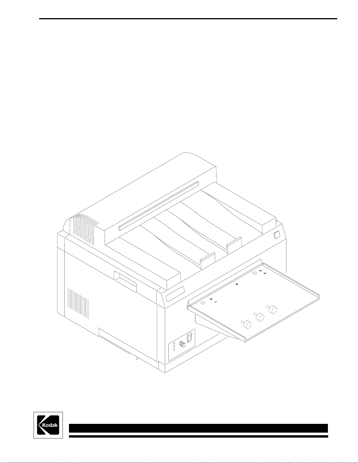
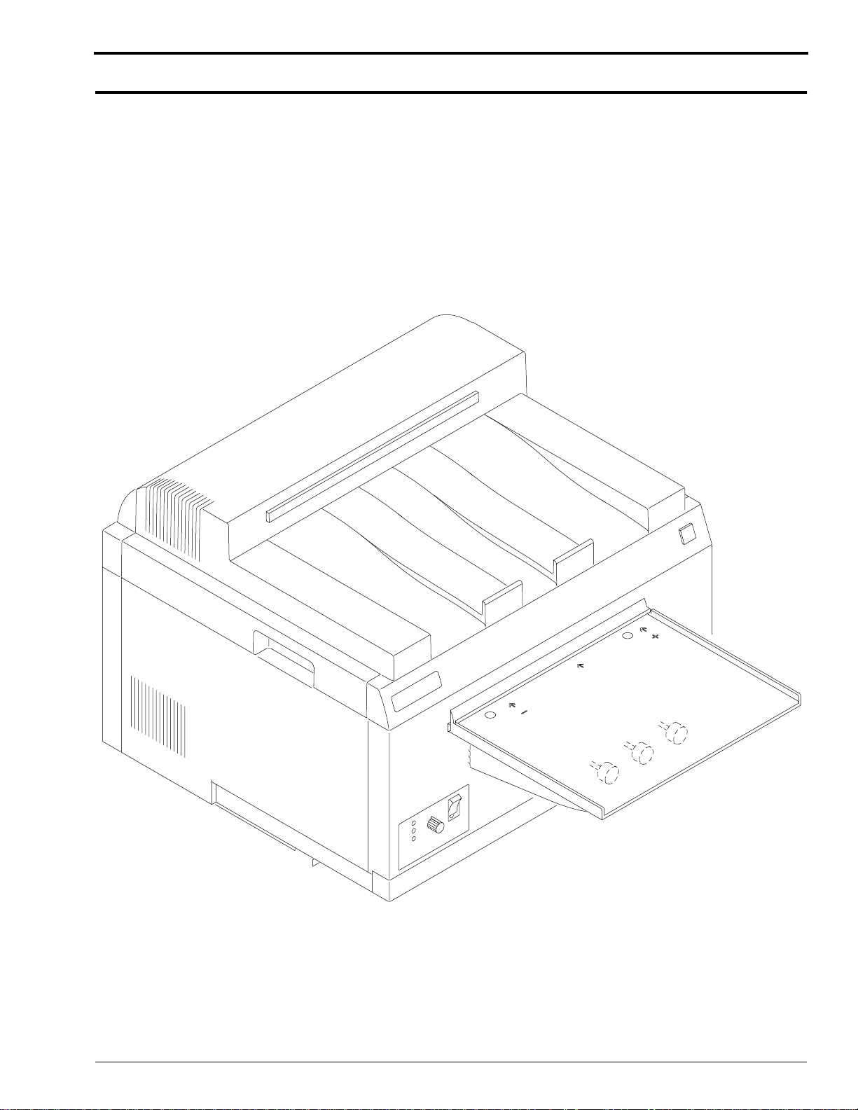
The Kodak X-Omat M43, M43A, and Clinic 1 Processors are compact, table-top processors used for
processing medical x-ray films. The Kodak X-Omat M43 and M43A Processors are designed to
perform primarily in the hospital satellite market. The Kodak X-Omat Clinic 1 Processor is designed
to perform primarily in the non-hospital market. The processors use a roller transport technology to
reliably process sheet film ranging in size from 10 x 10 cm to 35 x 43 cm (4 x 4 in. to
14 x 17 in.).
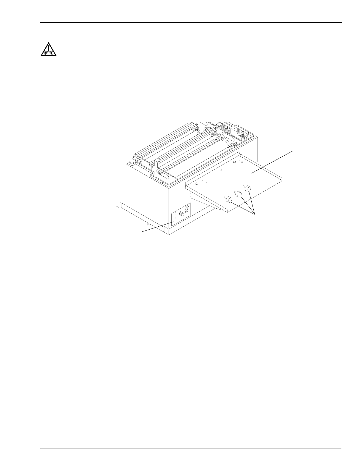
Figure 1 Front View of the Processor
Overview
H130_0009DA
981089 – September 1995 3
Page 4

OPERATOR MANUAL
Optional Accessories and Kits
Mounting Stand: An optional stand is available from Kodak. The processor stand provides a sturdy
work surface for the processor and occupies a minimum amount of space. By using the optional Kodak
M35, M43, Clinic 1 Mounting Stand, you are ensured that the processor will be at a convenient height
for feeding films. The Mounting Stand also provides the convenience of a slide-out shelf in the base
on which you may store replenishment supply tanks. Order CAT No. 808 1176.
Lighttight Feed Tray: An optional Lighttight Feed Tray Kit is available from Kodak. The Lighttight
Feed Tray allows you to turn on the darkroom lights immediately upon feeding the last sheet of film.
Order CAT No. 188 0335.
Transformer Kit: If your site does not meet the voltage specifications as outlined in the Site
Specifications, Publication Number 981087, a qualified service person can install a Transformer Kit to
ensure that your voltage will be within the correct specifications at all times. For Clinic 1 and M43A
sites whose voltage is not within the range of 104 to 127 V AC at all times, order CAT No. 167 4340.
For M43 sites whose voltage is not within the range of 207 to 253 V AC at all times, order
CAT No. 171 0292. Be sure when having a Transformer Kit installed, that it is installed according to
local codes.
Seismic Anchor Bracket Kit: If the processor is to be installed in California or in any area where the
threat of earthquakes or tremors exists, you can order the Seismic Anchor Bracket Kit. Use the
hardware supplied with the Mounting Stand to securely attach the processor to the Stand. The Seismic
Anchor Bracket Kit includes the hardware to enable a qualified service person to secure the Mounting
Stand to the floor. Order Part No. 261413. Be sure when having a Seismic Anchor Bracket Kit
installed, that it is installed according to local codes.
Vent Duct Adapter Kit: If you need venting capability, order a Vent Duct Adapter Kit that connects
to the processor. This kit can be used with the Auxiliary Ventilation Fan Kit (detailed below). For the
Vent Duct Adapter Kit, order CAT No. 143 4943.
Auxiliary Ventilation Fan Kit: If your site does not meet the specifications for room air changes as
outlined in the Site Specifications, Publication Number 981087, a qualified service person can install
the Kodak Auxiliary Ventilation Fan Kit with the Vent Duct Adapter Kit (detailed above). Order
Part No. 264503. Be sure when having a Ventilation Fan Kit installed, that it is installed according to
local codes. This kit is available for 115 V AC only and has a capacity of 122 cubic feet per minute.
Installation Kit: If your qualified service person is installing the Clinic 1 processor, the Installation
Kit provides all of the components necessary to install the processor. These parts are included when
purchasing the M43 and M43A processor models. Order CAT No. 863 2754.
Through-the-Wall Kit: If your qualified service person is installing the processor through the
darkroom wall, this kit includes all the components necessary to complete the installation. This kit
assumes the use of the Kodak M35, M43, Clinic 1 Mounting Stand (detailed above). For the Throughthe-Wall Kit, order CAT No. 871 3109.
4 September 1995 – 981089
Page 5
Operator Display
+
-
Ready
Wait
Service
Dryer
Temperature
H130_0003AA
H130_0003ACG
Breaker CB1
Main Circuit
Indicators
Status
Developer
Display
Temperature
Ready
Wait
Service
Dryer
Temperature
+
-
H130_0018AA
ON
-1-
-0-
OFF
Breaker CB1
Main Circuit
Indicators
Status
H130_0018ACE
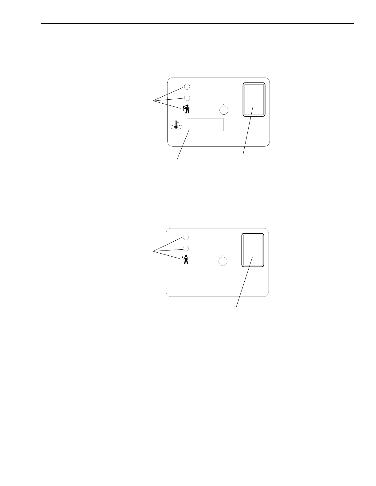
Figure 2 Display Panel of the M43 and M43A Processors
Overview
Figure 3 Display Panel of the Clinic 1 Processor
981089 – September 1995 5
Page 6

OPERATOR MANUAL
The Display Panel provides you with the following status conditions:
• Ready or Not Ready
• Warning and Error Conditions
• Current Temperature of the Developer (Models M43 and M43A Processors Only).
The 3 Status Indicators on the Display Panel provide you with the following information:
• Ready
– indicates that the processor is ready to accept film.
• Wait
– a blinking Wait Indicator means that the processor has not yet reached optimum film
processing conditions, see Page 33 for additional information.
– a solid Wait Indicator means that a film is being fed and has not yet cleared the Feed Tray.
• Service
– a blinking Service Indicator means that the processor has an error condition that you may be
able to correct. See Table 4 on Page 34 for possible remedies.
– a solid Service Indicator means that the processor is in the diagnostic mode. Call your service
provider.
6 September 1995 – 981089
Page 7

Processor Setup Options
The processor software allows for 4 optional configurations.
• Celsius or Fahrenheit Developer Temperature Display Units (Models M43 and M43A Processors
Only)
• Standard or Flooded Replenishment
• Standby Mode or Continuous Mode
• Low or Continuous Water Usage Mode
The 4 optional configurations can only be selected by qualified service personnel. Typically, the
options are configured at the time of installation, but you may change the options at any time by calling
your service provider.
Developer Temperature Display Units: (Models M43 and M43A Processors Only) You may
choose between degrees Celsius (°C) or degrees Fahrenheit (°F). The processor is factory set to display
Celsius units. To display Fahrenheit units, call your service provider.
Standard or Flooded Replenishment: The processor is factory set to the Standard Replenishment
Mode, but you may choose to set up the processor for flooded replenishment. Flooded Replenishment
Mode is intended for sites having low film volumes. Refer to the Replenishment Sheet, Publication
No. 1C0578, for low volume specifications. In the Flooded Replenishment Mode, every 24 minutes
the processor pumps the correct volume of replenishment solutions to process the equivalent of one 35
x 43 cm (14 x 17 in.) sheet of film. If you wish to operate the processor in Flooded Replenishment
Mode, call your service provider.
Standby Mode or Continuous Mode: The processor is factory set for the Standby Mode. In the
Standby Mode the processor’s Main Drive, Dryer Blower, Dryer Heater, and Wash Pump remain off.
Note: The Wash Pump may turn on during Standby Mode if cooling for the developer is required.
Standby Mode conserves both electricity and water and minimizes wear on moving parts. Ordinarily,
you may allow the processor to operate in Standby Mode. If you have selected the Continuous Mode,
the processor never enters a standby condition. This mode can be used in extreme conditions to
maintain optimum processing. For example: very cold ambient conditions, below 15°C (59°F); low
voltage sites; or sites running large films continuously back to back for long periods of time. If you
wish to operate the processor in the Continuous Mode, call your service provider.
Low or Continuous Water Usage Mode: The processor is factory set for Continuous Water Usage
Mode. In this mode, water runs at one litre per minute. This allows fresh water to circulate through
the processor and prevent biological growth. If biological growth is not a concern and you wish to
operate the processor in Low Water Usage Mode, call your service provider.
Overview
981089 – September 1995 7
Page 8
OPERATOR MANUAL
Replenishment Solutions
Mixing the Chemicals
Warning
Wear rubber gloves, safety glasses, and protective clothing when mixing chemicals and filling the tanks.
Important
• When mixing chemical solutions, follow all instructions and precautions on the labels of the chemical bottles.
• Mix only a 2-week supply of developer replenishment.
[1] Following all directions provided with the chemicals, mix at least 19 litres (5 gallons) of replenishment
solution.
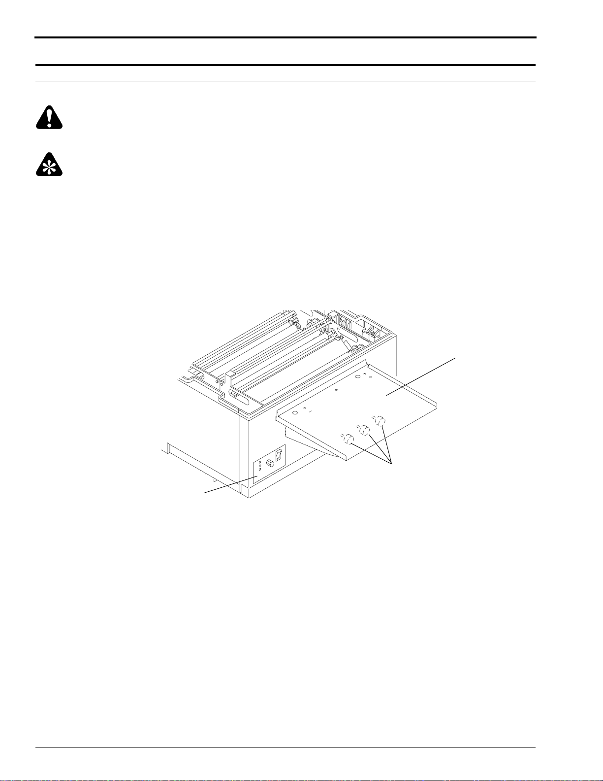
[2] Before adding fresh chemicals to an empty processor, check that the developer and fixer Drain Valves are fully
1
closed. The Drain Valve Knobs should be rotated
Figure 4 Closing the Drain Valves
/4 turn.
Display
Panel
Drain Valves
Feed Tray
H130_0019BCH
H130_0019BA
8 September 1995 – 981089
Page 9
Replenishment Solutions
Draining the Processor Tanks
Caution
If using a Silver Recovery Unit, disconnect the Drain Tube from the input side of the Silver Recovery Unit before
you open the Drain Valve. This will avoid flooding. Drain the fixer solution into a container or directly into the floor
drain. Check the local codes before draining solutions into a floor drain.
[1] Drain the Tank by rotating the Drain Valve Knob in either direction
place. When the Tank is drained, close the Drain Valve by rotating the Drain Valve Knob
direction.
Figure 5 Draining the Tanks
1
/4 turn. You will feel the stem lock into
1
/4 turn in either
Feed Tray
Drain Valves
Display
Panel
[2] Remove the Dryer Rack.
[3] Remove the Fixer and Developer Evaporation Covers.
[4] Remove the Fixer Rack and Developer Rack.
• To prevent solutions from one Tank spilling over into the next Tank, always:
– use the Splash Guard, Part No. 1C4019
– lower or raise the Racks very slowly when installing or removing them
• To prevent solutions from dripping into the processor or onto the Feed Tray:
– use the Drip Tray, Part No. 1C4011, when carrying Racks to and from the processor
– carefully tip the Racks when removing them from the processor to drain the remaining solution
– remove the Racks from the side of the processor, not from the front or back
[5] Rinse and thoroughly wipe the Racks and Evaporation Covers with a clean, lint-free cloth.
H130_0019BCH
H130_0019BA
981089 – September 1995 9
Page 10
OPERATOR MANUAL
Filling the Fixer Tank
Warning
• To avoid spilling processing solutions onto electrical components:
– fill the Tanks from the Non-Drive side as shown
– always fill the Tanks with the Access Panels in place
1
[1] Make sure that the Fixer Drain Valve is closed by rotating it
[2] Install the Splash Guard, Part No. 1C4019, between the Fixer Tank and the Developer Tank. See the figure for
the correct position of the Splash Guard.
Caution
Relatively small amounts of fixer can seriously contaminate the developer. If you are changing solutions in both the
Developer Tank and the Fixer Tank, fill the Fixer Tank first so that you can thoroughly clean any fixer solution that
spilled into the Developer Tank.
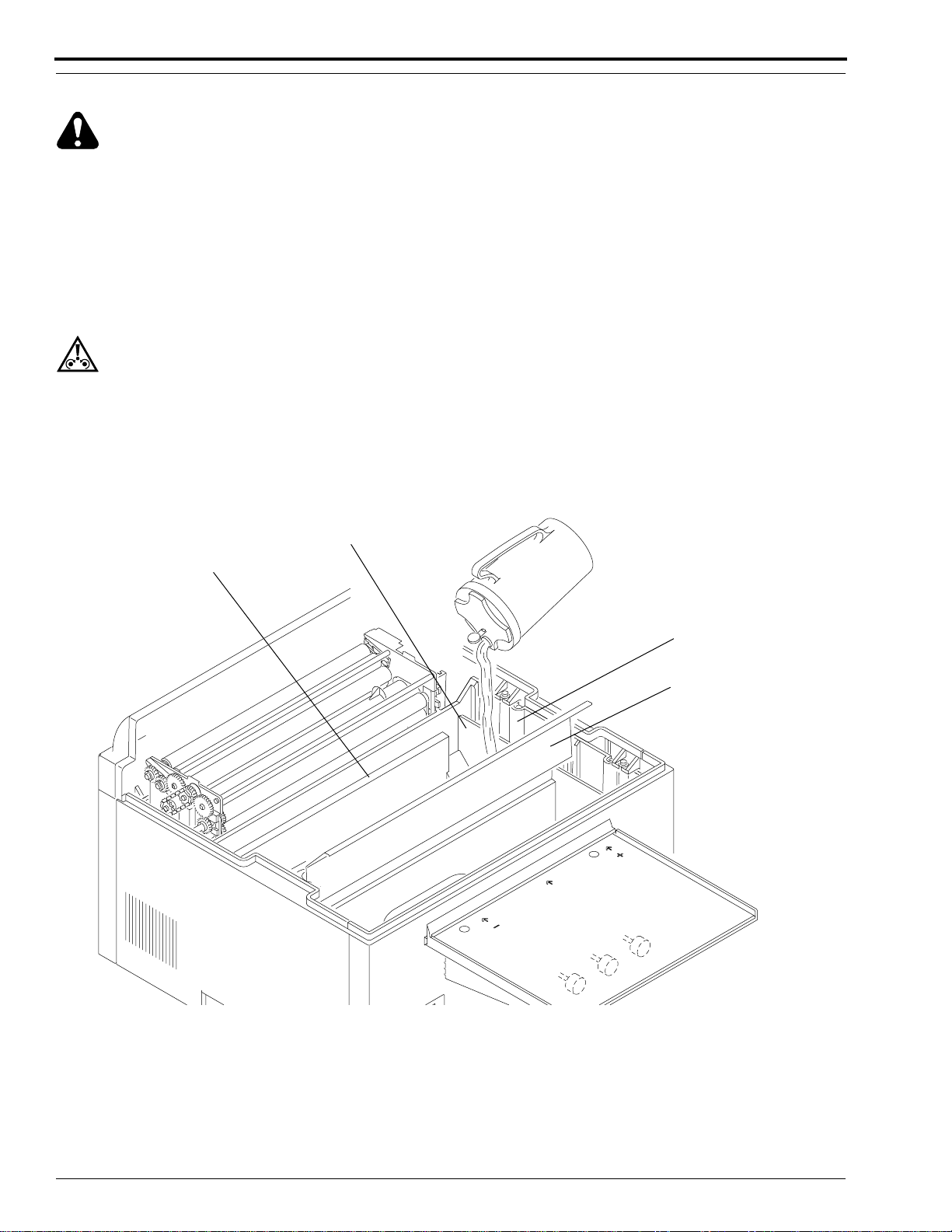
[3] Slowly pour fixer solution into the empty Fixer Tank until the level of the solution in the Fixer Tank is at the
top of the Step.
/4 turn.
Figure 6 Checking the Level of the Fixer Solution
Overflow Weir
Step
Fixer Tank
Splash Guard
P/N 1C4019
H130_0110HCD
H130_0110HA
10 September 1995 – 981089
Page 11
Replenishment Solutions
[4] Wipe any solution that spilled on the Splash Guard using a clean, damp, lint-free cloth.
[5] Very carefully, install the Fixer Rack into the Fixer Tank onto the edge of the Splash Guard. You can identify
the Fixer Rack by the blue Wire Tie.
(a) Check that the fixer solution did not spill or splash into the Developer Tank. If necessary, rinse and then
dry the Developer Tank by wiping the Tank with a clean, lint-free cloth.
(b) Check that the Fixer Rack is seated firmly in the Fixer Tank.
[6] Check that the level of the solution in the Fixer Tank is at the top of the Overflow Weir. If necessary, add more
solution. See Figure 6 on Page 10.
[7] Install the Fixer Evaporation Cover between the Fixer Rack and the Wash Rack. Position the Evaporation
Cover on the Tie Rods of the 2 Racks as shown.
Figure 7 Installing the Fixer Evaporation Cover
Fixer Evaporation Cover
Fixer Rack
Wire Tie
H130_0135HCD
H130_0135HA
981089 – September 1995 11
Page 12
OPERATOR MANUAL
Filling the Developer Tank
Warning
• To avoid spilling processing solutions onto electrical components:
– fill the Tanks from the Non-Drive side as shown
– always fill the Tanks with the Access Panels in place
Caution
Relatively small amounts of fixer can seriously contaminate the developer. If you are changing solutions in both the
Developer Tank and the Fixer Tank, fill the Fixer Tank first so that you can thoroughly clean any fixer solution that
spilled into the Developer Tank.
• To prevent solutions from one Tank spilling over into the next Tank, always:
– use the Splash Guard, Part No. 1C4019
– lower or raise the Racks very slowly when installing or removing them
• To prevent solutions from dripping into the processor or onto the Feed Tray:
– use the Drip Tray, Part No. 1C4011, when transporting Racks from the processor
– carefully tip the Racks when removing them from the processor to drain the remaining solution
– remove the Racks from the side of the processor, not from the front or back
1
[1] Check that the Developer Drain Valve is closed by rotating it
/4 turn.
Warning
Wear rubber gloves, safety glasses, and protective clothing when mixing chemicals and filling the tanks.
[2] Check that the Developer Tank does not contain any spills of fixer solution. If necessary, rinse and then dry
the Developer Tank by wiping the Tank with a clean, lint-free cloth.
Important
It is important to do the following steps in the correct sequence to prevent Kodak RP X-Omat Developer Starter from
going down the Drain Hoses.
[3] Pour developer solution into the Developer Tank until the level of the solution completely covers the Heat
Exchanger in the bottom of the Tank. See Figure 8 on Page 13.
12 September 1995 – 981089
Page 13

Replenishment Solutions
[4] Pour 266 mL (9 fl oz.) of Kodak RP X-Omat Developer Starter into the Developer Tank.
[5] Pour more developer solution into the Developer Tank until the level of the solution reaches the top of the Step
in the Developer Tank.
Figure 8 Checking the Level of the Developer Solution
Splash Guard
P/N 1C4019
Overflow
Weir
Developer
Tank
Step
Heat Exchanger
H130_0109HCF
H130_0109HA
[6] Remove the Splash Guard from between the Fixer Tank and the Developer Tank. Wipe any spilled solution
from the Splash Guard using a clean, damp, lint-free cloth.
[7] Very carefully, install the Developer Rack into the Developer Tank. You can identify the Developer Rack by
the red Wire Tie.
a. Be careful not to spill any developer solution into the Fixer Tank.
b. Check that the Developer Rack is seated firmly in the Developer Tank.
• Small amounts of developer solution in the Fixer Tank will not contaminate the fixer solution, but will
degrade the fixer solution.
981089 – September 1995 13
Page 14

OPERATOR MANUAL
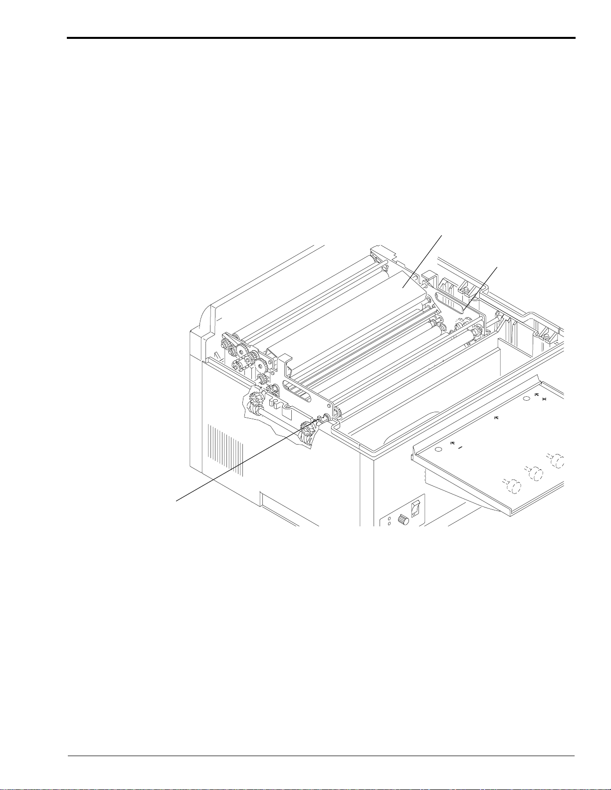
[8] Check that the Drive Gears on the Developer and Fixer Racks correctly engage the Gears on the Drive Shaft.
[9] Using a soft, lint-free cloth, dry the Entrance Rollers on the Developer and Fixer Racks to prevent artifacts.
[10] Check that the level of the solution in the Developer Tank is at the top of the Overflow Weir. If necessary, add
more solution. See Figure 8 on Page 13.
[11] Install the Developer Evaporation Cover between the Developer Rack and the Fixer Rack. Position the
Evaporation Cover on the Tie Rods of the 2 Racks as shown.
Figure 9 Installing the Developer Evaporation Cover
Fixer Evaporation Cover
Developer
Evaporation
Cover
Drive Gear
Main Drive Shaft
Circuit Breaker CB1
[12] Check that the Wash Drain Valve is closed.
[13] Install the Dryer Rack and check that it is seated properly.
[14] Install the Top Cover onto the processor.
[15] Turn on the main water supply.
[16] Turn on the processor by moving the Main Circuit Breaker CB1 to the “1” position.
[17] Allow the processor to operate for at least 60 seconds to mix the developer and starter solutions.
H130_0139HCD
H130_0139HA
14 September 1995 – 981089
Page 15

Replenishment Solutions
Replenishment Calibration Check Procedure
The Replenishment Pumps are preset at the factory so that they will pump proportional volumes of developer and
fixer replenishment solutions. The replenishment rate for the fixer should always remain 15 to 20% greater than the
replenishment rate for the developer. When checking the replenishment rate, always check the replenishment rates
for both the developer and the fixer, but make any adjustment using the developer replenishment solution.
For the recommended replenishment rates for developer and fixer, see the replenishment rate information sheet,
Publication No. 1C0578, provided in the front pocket of your publications binder.
[1] To enter the Replenishment Calibration Check Mode:
• Check that the processor is on (CB1 in the “1” position).
• Remove the Top Cover.
Note
When the Top Cover is removed, the Safety Interlock is enabled. You will not see or hear any of the individual
components of the processor running.
[2] Insert the Developer Replenishment Check Tube into a Graduated Cylinder.
Note
The Graduated Cylinder must be capable of containing at least 500 mL of solution. Use a 500 mL Graduated
Cylinder TL-1435.
Figure 10 Checking the Developer Replenishment Rate
Developer
Replenishment
Check Tube
Fixer
Replenishment
Check Tube
Feed Tray
Graduated Cylinder
H130_0021BCB
H130_0021BA
981089 – September 1995 15
Page 16

OPERATOR MANUAL
[3] Check that there is no air in the Replenishment Hoses.
[4] Insert and remove a small sheet of film into the area indicated by the middle arrow on the Feed Tray.
• The film must pass under the Middle Film Sensor.
• Do not allow the sheet of film to block the Right (+) Film Sensor or Left (-) Film Sensor.
• The processor will beep twice to acknowledge the request for replenishment and then deliver replenishment
to the Graduated Cylinder.
• The processor should pump the preset volume of developer and fixer replenishment solution for a 35 x
43 cm (14 x 17 in.) sheet of film.
[5] After the Replenishment Pump stops, repeat Step 4 two additional times.
[6] Measure and record the volume of developer replenishment solution in the Graduated Cylinder. Divide the
volume by 3 to calculate the average amount of developer replenishment for each 35 x 43 cm (14 x 17 in.) sheet
of film.
Figure 11 Inserting and Removing Film Under the Middle Film Sensor
Right (Plus)
Film Sensor
Middle
Film Sensor
Left (Minus)
Film Sensor
H130_0019BCI
H130_0019BA
16 September 1995 – 981089
Page 17

Replenishment Solutions
[7] Compare your results to the recommended volumes listed in the Replenishment Rate Sheet, Publication
No. 1C0578, which is located in the front pocket of your publications binder.
Note
Any time you adjust the replenishment rate, you are adjusting the replenishment volume for both developer and
fixer. Each time you increase or decrease the replenishment rate by inserting and removing a sheet of film under
either the Right (+) Film sensor or Left (-) Film sensor, you are changing both of the replenishment rates by
approximately 5 mL.
(a) If you measured the correct volume of developer replenishment solution, do not make any
replenishment adjustments. Go to Step 8 on Page 18.
(b) If you measured more than the recommended volume of developer replenishment solution, go to
Step (m) below.
(c) If you measured less than the recommended volume of developer replenishment solution, do the
following steps to increase the rate of replenishment.
(d) Empty the replenishment solution from the Graduated Cylinder.
(e) Insert and remove a small sheet of film under theRight (+) Film Sensor on the right side of the Feed Tray.
Listen for the processor to beep once. Each beep represents a 5 mL increase in replenishment volume.
Note
To make large changes in the replenishment rate, you may insert and remove a sheet of film from the Right (+) Film
Sensor several times consecutively.
(f) Again, insert the Developer Replenishment Check Tube into the Graduated Cylinder.
(g) Again, insert and remove a small sheet of film under the Middle Film Sensor. Wait for the processor to
beep twice and deliver replenishment solution to the Graduated Cylinder.
(h) After the Replenishment Pump stops, repeat the previous step two additional times.
(i) Measure the volume of developer replenishment solution in the Graduated Cylinder. Divide the volume
by 3 to calculate the average measurement.
(j) If the average measurement is less than the recommended volume by more than 3 mL, continue increasing
the replenishment rate as necessary.
(k) When the developer replenishment rate is correct, push the Developer Replenishment Check Tube down
into the Developer Tank to its original position.
(l) Advance to Step 9 on Page 18.
(m) If you measured more than the recommended volume of developer replenishment solution, do the
following steps to decrease the rate of replenishment.
(n) Empty the replenishment solution from the Graduated Cylinder.
(o) Insert and remove a small sheet of film under the Left (-) Film Sensor on the left side of the Feed Tray.
Listen for the processor to beep once.
Note
To make large changes in the replenishment rate, you may insert and remove a sheet of film from the Left (-) Film
Sensor several times consecutively.
(p) Insert the Developer Replenishment Check tube into the Graduated Cylinder.
(q) Again, insert and remove a small sheet of film under the Middle Film Sensor. Wait for the processor to
beep twice and deliver replenishment solution to the Graduated Cylinder.
(r) After the Replenishment Pump stops, repeat the previous step two additional times.
(s) Measure the volume of developer replenishment solution in the Graduated Cylinder. Divide the volume
by 3 to calculate the average measurement.
(t) If the average measurement is more than the recommended volume by more than 3 mL, continue
decreasing the replenishment rate as necessary.
981089 – September 1995 17
Page 18

OPERATOR MANUAL
[8] When the developer replenishment rate is correct, push the Developer Replenishment Check Tube down into
the Developer Tank to its original position.
[9] Clean and rinse the Graduated Cylinder and then insert the Fixer Replenishment Check Tube into the
Graduated Cylinder.
Note
The Graduated Cylinder must be capable of containing at least 500 mL of solution.
[10] Insert and remove a small sheet of film under the Middle Film Sensor.
a. Do not allow the sheet of film to block the Right (+) Film Sensor or Left (-) Film Sensor.
b. The processor will beep twice to acknowledge the request for replenishment.
c. The replenishment system will deliver the preset volume of fixer solution into the Graduated Cylinder.
[11] After the Replenishment Pump stops, insert and remove the sheet of film two additional times.
[12] Measure the volume of fixer replenishment solution in the Graduated Cylinder. Divide the volume by 3 to
calculate the average measurement.
[13] Check that the Fixer Replenishment Check Tube is pushed down into the Fixer Tank to its original position.
[14] Calculate the ratio of developer replenishment to fixer replenishment. Divide the average fixer replenishment
rate you obtained by the average developer replenishment rate you obtained.
[15] Compare the ratio you obtained to the recommended ratio. See the replenishment rate information sheet,
Publication No. 1C0578, located in the front pocket of the publications binder for the recommended volumes
of replenishment and expected ratios.
Note
Formula: Fixer ÷ Developer = Ratio
Example: 100 mL fixer ÷ 80 mL developer = 1.25 (Ratio)
(a) If you do not obtain the recommended ratio, check for kinked hoses outside of the processor or air in the
lines. If this does not correct the problem, call your service provider.
18 September 1995 – 981089
Page 19

Operating Instructions
Operating Instructions
Daily Start-Up
[1] Check that the level of processing solutions is at the Overflow Weir. If the solutions are not at the Overflow
Weir, place film under the Middle Film Sensor to fill the Tank.
[2] Install the Top Cover on the processor.
[3] In Low Water Usage Mode, close the Wash Drain Valve by rotating it
[4] Turn on the water supply to the processor.
[5] Check that the Developer and Fixer Replenisher Tanks contain enough solution for the day’s operation.
[6] Check that the Feed Tray is clean.
[7] Turn on the processor by moving the Main Circuit Breaker CB1 to the “1” position.
[8] Allow the processor to warm up.
• 10 to 20 minutes in average site conditions
• up to 45 minutes in extreme site conditions
[9] When the Ready Indicator illuminates and the Wait Indicator turns off, feed a test sheet of pre-exposed, non-
processed film or a new sheet of cleanup film to verify correct roller transport and operation of the processor.
• the solutions are at the correct temperature
• the Dryer is at the setpoint temperature
• you may feed film
• the solutions are at the correct temperature
• the Dryer has not reached setpoint temperature
• emergency films may be run, but may exit wet or damp
• If films are wet and feel tacky when they exit the Dryer Assembly, then the Dryer setpoint temperature is
too low.
• If films are over dry and feel hot to the touch when they exit the Dryer Assembly, then the Dryer setpoint
temperature is too high.
1
/4 turn.
Note
Using previously processed film as clean-up film can contaminate the solution in the Developer Tank due to the
residual Fixer solution on that film.
Figure 12 Preparing for Daily Start-Up
Feed Tray
Ready
Indicator
Main Circuit Breaker CB1
981089 – September 1995 19
Wash Drain Valve
H130_0019BCJ
H130_0019BA
Page 20

OPERATOR MANUAL
Operating Notes
When the Ready Indicator illuminates and neither the Wait Indicator nor Service Indicator is
illuminated or blinking, it indicates that:
• the solutions are at the correct temperature
• the Dryer is at the setpoint temperature
• you may feed film
When the Ready Indicator illuminates and the Wait Indicator is blinking 3 times, it indicates that:
• the solutions are at the correct temperature
• the Dryer has not reached setpoint temperature
• emergency films may be run, but may exit wet or damp
When the Wait Indicator or the Service Indicator is blinking, the blink pattern will be
1
⁄2 second OFF with a 2-second delay between the blink patterns.
and
Table 1 Indicator Blink Patterns
Action Ready Wait Service
Feed Film On Off Off
Feed Film
but may exit wet
On Blinks 3
Times
Off
Wait - Film in Process On On Off
Do Not Feed Film
Off Blink or Off Blink or Off
Wait for the Film Feed Signal
1
⁄2second ON
Figure 13 Identifying the Status Indicator Lights
Ready
Indicator
Service
Indicator
Wait
Indicator
Ready
Wait
Service
Dryer
Temperature
-
+
H130_0018ACG
ON
-1-
-0-
OFF
H130_0018AA
20 September 1995 – 981089
Page 21

Operating Instructions
Ready
Wait
Service
Dryer
Temperature
+
-
H130_0018AA
ON
-1-
-0-
OFF
H130_0018ACF
Dryer Temperature
Control Knob
Adjusting the Dryer Temperature
When films exit the Dryer Assembly, they should be “just dry.” The films should feel cool to the touch, but be dry.
• If films are wet and feel tacky when they exit the Dryer Assembly, then the Dryer setpoint temperature is too low.
• If films are over dry and feel hot to the touch when they exit the Dryer Assembly, then the Dryer setpoint
temperature is too high.
Note
Wait 5 minutes between Dryer temperature adjustments so that the Dryer can reach the new setpoint temperature.
To adjust the Dryer setpoint temperature to the correct temperature setting for your most commonly used
film size and type, follow the steps below.
[1] Turn the Dryer Temperature Control Knob, located on the Display Panel on the front of the processor, so that
the Pointer on the Knob points straight up ↑.
(a) If you are turning the Dryer Temperature Control Knob from its full counterclockwise position, you
will feel 5 detents as you turn the Knob to its upright position.
Figure 14 Locating the Dryer Temperature Control Knob
[2] Allow 5 minutes for the Dryer temperature to stabilize and then feed a test sheet of pre-exposed, non-
processed film.
Note
• Select the film type and size that will be most commonly used. Different film types require different drying
temperatures for optimum results.
• If you are increasing the Dryer setpoint temperature, the Ready Indicator will illuminate and the Wait Indicator
will turn off once the Dryer has reached the new setpoint temperature.
• If you are decreasing the Dryer setpoint temperature, the Wait Indicator will not illuminate when the Dryer has
[3] Examine how the sheet of film feels to the touch as it exits the Dryer Assembly.
981089 – September 1995 21
reached its new setpoint temperature. Therefore, allow 5 minutes after decreasing the Dryer setpoint temperature
for the Dryer to reach its new setpoint temperature. The processor may enter Standby Mode during this time.
a. If the sheet of film is damp or tacky when it exits the Dryer Assembly:
• turn the Dryer Temperature Control Knob clockwise one detent position.
b. If the sheet of film is dry and hot when it exits the Dryer Assembly:
• turn the Dryer Temperature Control Knob counterclockwise one detent position.
Page 22

OPERATOR MANUAL
[4] Repeat Steps 2 and 3 until the film exits “just dry.”
Film Feeding Procedure
Feeding Sheet Films:
Caution
• Do not pull back films after you begin to feed them into the processor.
• Feed all sheet films except 10 x 10 cm (4 x 4 in.) sheets square with the left edge of the Film Guide.
Feed 10 x 10 cm (4 x 4 in.) sheets square with the right edge of the Film Guide. See Figure 15 on
Page 23 for the recommended film feeding procedure. The arrows indicate the direction in which
you should feed the films into the processor for optimum replenishment.
• Feed the next sheet of film after you hear the film-feed signal and the Wait Indicator turns off. The
film-feed signal alerts you that the trailing edge of the sheet of film has left the Film Sensors and
is fully into the processor. At this point, you may either feed another sheet of film, or turn on the
room lights.
• Feed single-emulsion films with the emulsion-side up.
22 September 1995 – 981089
Page 23

Operating Instructions
Note
The Receiving Bin is only 35 cm (14 in.) long. Therefore, when sheets of film longer than 35 cm
(14 in.) exit the processor, you must manually assist the films as they enter the Receiving Bin.
Note
Feed all films square with the left side of the Film Guide except where noted differently.
Figure 15 Recommended Feeding of X-Ray Film Sizes
1 each
35 x 43 cm
or
14 X 17 in.
1 each
24 x 30 cm,
10 x 12 in.
1 each
24 x 24 cm
2 each
1 each
or
9 x 9 in.
1 each
35 x 35 cm
or
12.5 x 12.5 in.
2 each
1 each
18 x 43 cm
2 each
1 each
33 x 41 cm,
30 x 40 cm,
30 x 35 cm,
11 x 14 in.,
or
12 x 15 in.
18 x 43 cm
2 each
18 x 24 cm
or
8 x 10 in.
18 x 24 cm
or
8 x 10 in.
6.5 x 8.5 in.
Feed these films left justified.
Feed these films right justified.
1 each
10 x 10 cm
4 x 4 in.
13 x 18 cm,
3.5 x 8 in.,
5 x 7 in.
H130_9002DC
981089 – September 1995 23
Page 24

OPERATOR MANUAL
Shutdown
[1] Turn off the processor by moving the Main Circuit Breaker CB1 on the processor to the “O” position.
[2] Turn off the main power to the processor.
[3] Turn off the water supply to the processor.
[4] In Low Water Usage Mode, open the Wash Drain Valve by rotating it
Note
With Modification No. 2, Part No. 8B6930, installed, the processor will drain automatically overnight.
[5] Do the “Daily Cleanup” procedure on Page 25.
Figure 16 Shutting Down the Processor
Main
Circuit
Breaker
CB1
1
/4 turn.
Wash Drain Valve
H130_0019BCK
H130_0019BA
24 September 1995 – 981089
Page 25

Preventive Maintenance
Daily Cleanup
[1] Turn off the processor by moving the Main Circuit Breaker CB1 to the “O” position.
[2] Turn off the main power to the processor.
Note
To avoid getting debris in the processor, do not use a sponge to clean any processor parts.
[3] Wipe the following parts using warm water and a clean, damp, lint-free cloth:
• Feed Tray
• Top Cover
• Front, Back, and Side Access Panels
Preventive Maintenance
981089 – September 1995 25
Page 26

OPERATOR MANUAL
Weekly Preventive Maintenance Procedures
Warning
Wear rubber gloves, safety glasses, and protective clothing when doing any maintenance procedure. Report any
change in the operating condition of the processor to your service provider.
[1] Check that the “Daily Cleanup” section was completed as outlined.
[2] Remove the Top Cover, if it is not already removed.
Caution
• Handle these assemblies carefully to prevent changing their alignment.
• Do not clean the Racks or Rollers using abrasive materials.
• Do not wash the Rollers with water hotter than 37.5°C (100°F).
• Use the Splash Guard, Part No. 1C4019, between the Developer Tank and the Fixer Tank. Using the Splash
Guard will prevent contamination of the developer solution when you remove the Fixer Rack. Using the Drip
Tray, Part No.1C4011, when you remove or install any of the Racks will also help to prevent contamination of
the processing solutions.
Figure 17 Using the Splash Guard
Fixer Rack
Splash Guard
P/N 1C4019
Developer Tank
H130_0190HCB
H130_0190HA
26 September 1995 – 981089
Page 27

Preventive Maintenance
[3] Remove:
• Dryer Rack
• Evaporation Covers
• Wash Rack
• Fixer Rack
• Developer Rack
[4] Clean the Evaporation Covers and all the Racks with warm water and a clean, damp, lint-free cloth.
[5] Check that the holes in the Wash Tubes of the Wash Rack are clean and open.
(a) Using the Tab on the Upper Wash Tube, push the Wash Tube toward the Drive Side of the Wash Rack to
remove the Wash Tube.
(b) Use a Wash Tube Cleaning Brush Part No. TL-4833 or a toothbrush to clean any obstructions in the holes
of the Wash Tube. Do not use the Brush to clean the smooth surface of the Wash Tube. Only use the
Brush to clean the recessed area around the holes.
(c) Remove and clean the Lower Wash Tube.
(d) Install the Wash Tubes observing the Locator Key on the Non-Drive Sideplate.
Caution
Do not try to enlarge the size of the holes in the Wash Tube.
Figure 18 Removing the Upper Wash Tube of the Wash Rack
H130_0254BCA
H130_0254BA
Wash
Manifold
Tab
Upper Wash Tube
981089 – September 1995 27
Page 28

OPERATOR MANUAL
[6] Check that all the Rollers in the Racks turn freely.
[7] Check the squareness of all the Rack Assemblies.
(a) Place the Rack on a flat work surface.
Be sure that you position the Wash Rack on the flat surface so that the Wash Manifold overhangs the edge
of the table. See Figure 19.
Place the Dryer Rack on a flat work surface. See Figure 20.
(b) Check that the 2 Sideplates touch the flat surface evenly.
(c) Twist the Rack as necessary.
(d) If further adjustment is necessary, call your service provider.
Figure 19 Checking the Squareness of the Wash Rack
Wash
Rack
Sideplate
Sideplate
Wash
Screw (2)
Manifold
Figure 20 Checking the Squareness of the Dryer Rack
Tie
Rod (2)
flat surface
H130_0144ACB
H130_0144AA
Dryer
Rack
H130_0199ACA
H130_0199AA
28 September 1995 – 981089
Page 29

Preventive Maintenance
[8] Use a clean, damp, lint-free cloth to wipe all chemical residue from around the Film Detector Assembly.
[9] Wipe the Wash Tank with a clean, damp, lint-free cloth.
[10] Check that the Splash Guard is still positioned correctly between the Fixer Tank and the Developer Tank.
Caution
Install the Racks slowly to prevent contamination of the processing solutions.
[11] Install the parts in the following order making sure that all Drive Gears engage properly:
a. Fixer Rack (on the Edge of the Splash Guard)
• Remove the Splash Guard.
b. Developer Rack
c. Wash Rack
d. Evaporation Covers
e. Dryer Rack
[12] Wipe any chemical deposits from the processing section of the processor, and clean the Film Sensors.
[13] Install the Top Cover.
[14] Turn on the processor and check for correct operation by feeding a test film.
[15] Check that the building’s ventilation system is running and that all vents are open.
981089 – September 1995 29
Page 30

OPERATOR MANUAL
Recommended Monthly Maintenance
Warning
Wear rubber gloves, safety glasses, and protective clothing when doing any maintenance procedure. Report any
change in the operating condition of the processor to your service provider.
[1] Check that the “Daily Cleanup” section was completed as outlined on Page 25.
[2] Do up to Step 9 of the “Weekly Procedures” section outlined on Page 29.
[3] Do the “Replenishment Calibration Check Procedure” as outlined on Page 15.
1
[4] Drain all 3 Tanks by rotating the 3 Drain Valve Knobs
[5] Rinse the inside of all 3 Tanks with plenty of warm water.
[6] Clean any chemical residue from the Tanks by wiping the Tank walls with a clean, damp, lint-free cloth. To
prevent contamination, do not use the same cloth for the Fixer Tank and the Developer Tank.
[7] Close all 3 Drain Valves by rotating them
1
/4 turn.
[8] On all Racks, check:
(a) that all Rollers rotate freely
(b) that the Rollers are clean and smooth
(c) that the Gears do not have excessive wear
(d) that the Bearings do not have excessive wear
(e) that the E-Rings and Springs are not broken, missing, or corroded
(f) that the Drive Chain on the Wash Rack does not have excessive wear and is adjusted correctly
(g) that the Dryer Rack is not dusty or dirty
(h) rinse the Air Tubes with water
[9] If necessary, install new parts.
[10] Check the Racks for squareness.
[11] Place Clamps on the Replenishment Tubes and clean the Replenishment Strainers located between the
Replenishment Pump and the Replenisher Tanks.
[12] Check the recommended Water Supply Filter. Replace it if necessary.
[13] Fill the Tanks. See Pages 8 through 14.
/4 turn.
Caution
Install the Racks slowly to prevent contamination of the processing solutions.
[14] Install the parts in the following order:
1. Fixer Rack
2. Developer Rack
3. Wash Rack
4. Evaporation Covers
5. Dryer Rack
[15] Wipe any chemical deposits from the processing section of the processor, and clean the Film Sensors.
[16] Turn on the processor and check for correct operation by feeding a test film.
[17] Check the Drains for biological growth. If necessary, clean the Drains.
30 September 1995 – 981089
Page 31

Preventive Maintenance
Preventive Maintenance Schedule*
Service
Operator
Provider
Part or Assembly Weekly Monthly 6 Months**
Replenishment Tanks C
Wash Rack C I C(2), I, R
Wash Tubes in the Wash Rack C C(2), I, R
Developer Rack C I C(1), I, R
Fixer Rack C I C(2), I, R
Dryer Rack I C, I, R
Developer/Fixer Recirculation Pumps L
Bearings, Drive Gears, and Rollers in all Racks I, R
Squareness of all Racks I I I
Dryer Air Tubes C, I
Tension of the Dryer Drive Belt I, R
Filters for the Replenisher Strainers C C, R
Filter for the Building Water Supply I, R R
Drain Hoses I I
Ventilation of Exhaust (if connected) I T
Drive Motor Chain I, L
Incoming Water Solenoid Screen C
Developer Processor Tank C C(1)
Fixer Processor Tank C C(2)
Wash Processor Tank C C C(2)
Calibration of the Replenishment Pumps T T
Film Sensors C C C, T
Dryer Blower L
Drive Shaft Worm Gears L
Drive Shaft Thrust Bearing L
C = Rinse and clean carefully and completely
using warm water and a lint-free cloth.
C(1) =
Clean with Kodak Developer System
L = Lubricate with recommended material.
R = Replace parts, if necessary.
T = Test and adjust, if necessary.
Cleaner and Neutralizer.
C(2) =
Clean with Kodak Fixer/Wash System
Cleaner.
I = Inspect for condition and adjust, if
necessary.
*Actual usage and site characteristics may require shorter intervals between
maintenance. These guidelines are for locations adhering to Site Specifications
issued by Kodak. The customer or the trained service provider may perform the
weekly preventive maintenance.
**Maintenance performed at the 6-month time interval should be performed by an
M43/M43A/Clinic 1 trained service provider.
981089 – September 1995 31
Page 32

OPERATOR MANUAL
32 September 1995 – 981089
Page 33

Problem Solving
Problem Solving
Diagnosing the Blink Patterns on the Display Panel
When the processor is operating, the condition of the processor is indicated by the 3 status indicators as outlined
below.
• When the Ready Indicator illuminates and neither the Wait Indicator nor Service Indicator is illuminated or
blinking, it indicates that:
– Both the developer solution and the Dryer are at the correct temperature.
– You may feed film.
• When the Ready Indicator illuminates and the Wait Indicator is blinking 3 times, it indicates that:
– The solutions are at the correct temperature.
– The Dryer has not reached setpoint temperature.
– Emergency films may be run, but may exit wet or damp.
• When the Wait Indicator illuminates and remains illuminated while the processor is operating, it indicates:
– A film is being fed and is not yet off the Feed Tray.
– The Film Sensors may be blocked by dirt or other debris.
• When the Wait Indicator blinks on and off while the processor is operating, it indicates that:
– There is a temporary error condition.
– There is an error condition that the operator may be able to correct. See Table 3 on Page 33.
• When the Service Indicator blinks on and off while the processor is operating, it indicates that:
– There is an error condition that the operator may be able to correct. The pattern of on and off flashes
indicates the error code. If the operator cannot correct the error condition, call for service.
– If film is fed into the processor during a service error, the processor will beep 2 seconds “On” then 2 seconds
“Off,” while that film is processed.
• When the Service Indicator illuminates and remains illuminated while the processor is operating, it indicates
that:
– Service of the processor is required.
Table 2 Indicator Blink Patterns
Action Ready Wait Service
Feed Film On Off Off
Feed Film
but may exit wet
Wait - Film in Process
Wait for the Film Feed Signal
Do Not Feed Film Off Blink or Off Blink or Off
981089 – September 1995 33
On Blinks
3 Times
On On Off
Off
Page 34

OPERATOR MANUAL
Table 3 Wait Indicator Blink Patterns
Condition Ready Wait Service Action
Processor ready On Off Off NORMAL
No error, film being
fed
Developer is over the
set temperature
Developer is under
the set temperature
Dryer is under the set
temperature
Top Cover is not
seated properly
Diagnostic Error Off Off On
On On Off OPERATION
Off Blinks 1 time Off
Off Blinks 2 times Off
On Blinks 3 times Off
Off Off Off
• Check that the main water supply to the processor
is turned on.
• Check that the main water supply is between 4 and
°C (40 and 85°F).
29
• The processor will not enter Standby Mode.
• Call for service.
• Check the developer temperature
• Normal warm-up time from 22
20 minutes.
• For the Clinic 1 processor only, when feeding 6 or
more films back to back with cold water 4
°F), a brief Wait condition can occur.
(40
• Check that the WASH DRAIN VALVE is closed.
• Call for service.
• Check that the Dryer Temperature Control Knob
is at the correct setting. Lower the Dryer
temperature if the films exit hot.
• Normal warm-up time is:
– 15 to 20 minutes in average site conditions
– up to 45 minutes in extreme site conditions
NOTE: The Dryer Heater will turn off if the
developer solution is above the set
temperature. When the temperature
decreases, the Dryer Heater will turn on
again.
• Call for service.
• Install the Top Cover on the processor.
• Check that the Top Cover is positioned correctly.
• Check that the main power to the processor is
turned on.
• Call for service.
• Call for service.
°C (72°F) is 10 to
°C
34 September 1995 – 981089
Page 35

Problem Solving
Note
When errors occur, record the blink pattern in a Service Log Book. When requesting service, inform your service
provider of the recorded blink pattern to help minimize downtime.
Table 4 Error Conditions - Service Indicator Blink Patterns
Error Condition Ready Wait Service Action
Circuit Board Error Off Off Blinks 1 time
Loss of air flow Off Off Blinks 2 times
Air Vane Switch Error Off Off Blinks 3 times
Unable to determine
the developer
temperature
Dryer is over the
temperature
Unable to determine
the Dryer temperature
Film Detector LED
Error
Developer over set
temperature range
Off Off Blinks 4 times
Off Off Blinks 5 times
Off Off Blinks 6 times
Off Off Blinks 7 times
Off Off Blinks 8 times
• Call for service.
• Turn the processor off. Wait 5 seconds and turn
on the processor.
• Remove the Top Cover.
• Check that the Dryer Plenum is seated correctly.
• Install the Top Cover.
• If the problem recurs, call for service.
• Turn the processor off. Wait 5 seconds and turn
on the processor.
• If the problem recurs, call for service.
• Turn the processor off. Wait 5 seconds and turn
on the processor.
• If the problem recurs, call for service.
• Turn the processor off. Wait 5 seconds and turn
on the processor.
• Check that the Dryer Plenum is seated correctly.
• If the problem recurs, call for service.
• Turn the processor off. Wait 5 seconds and turn
on the processor.
• If the problem recurs, call for service.
• Clean the Film Sensors.
• Check for obstructions of the film detectors.
• If the problem recurs, call for service
.
• Check that the main water supply to the processor
is turned on and within 4 to 29.5
°C (40 to 85°F).
• Check that the WASH DRAIN VALVE is closed.
• Check that the Vent on the Side Access Panel of
the processor is free from obstruction.
• Check that the room ambient temperature is
within 15 and 30
• The processor will not enter Standby Mode in this
condition.
• This can be a temporary situation. Wait
15 minutes. If the problem has not cleared, call
for service.
981089 – September 1995 35
°C (59 and 86°F).
Page 36

OPERATOR MANUAL
Error Condition Ready Wait Service Action
Developer under set
temperature range
Dryer under set
temperature range
Off Off Blinks 9 times
Off Off Blinks 10 times
• Check that the room ambient temperature is
within 15 and 30
• This can be a temporary situation. Wait 15
minutes. If the problem has not cleared, call for
service.
• Check that the room ambient temperature is
within 15 and 30
• Turn the processor off. Wait 5 seconds and turn
on the processor.
• If the Vent Kit is installed, check for excessive
negative static pressure at the Exhaust Vent.
• If the problem recurs, call for service.
°C (59 and 86°F).
°C (59 and 86°F).
36 September 1995 – 981089
Page 37

Diagnosing Mechanical Problems
1. Transport Failure
2. Surface Artifacts
3. Abnormal Film Densities
4. Wet Films
5. Low Solution Levels
6. Overlapping of Films
123456
• • Film Feeding Error
Feed only single thicknesses of film. Feed next film only after
film feed signal. If there is no film feed signal, refer the
difficulty to qualified personnel.
•••• •
••
••••
•
• • • Remove any dirt from the Dryer Rollers, the Air Tubes, and especially
• • • • • Check the settings for correct replenishment. Check the replenishment
••
••
•••
•
••• •
••
••
•••
••
••
••
• Check that the Dryer and the Dryer Plenum are seated correctly.
••
• If the processor Tanks are not full, check that the Drain Valves are
Feed only compatible films.
Check that all Racks are seated correctly and that all Gears engage
•
correctly.
Check that the surfaces of all the Rollers, especially the Rollers in the
Wash Back, are clean and smooth.
from the Slots in the Air Tubes. Rinse the parts with water and wipe
them dry before installing them.
system outside the processor: Tubing kinks, Pump operation, and Film
Detector Sensors.
Adjust the Dryer Temperature Control Setting to the lowest possible
temperature that still allows good drying.
Remove any buildup of debris or chemicals from the Feed Tray and
Rollers that are above the level of the processing solution. Check the
Feed Tray and all Entrance and Exit Rollers for damaged surfaces.
• Clean any biological growth in the Wash Tank with a mild solution of
chlorine bleach. Use 60 mL (2 fl oz.) of bleach per 3.8 L (1 gallon) of
water. Wipe Tanks with a clean, soft, lint-free cloth.
closed and that the correct Drain Valves are installed. If necessary, call
your service provider.
Change any incorrectly mixed, exhausted, or contaminated chemicals.
Fill the Replenishment Tanks if necessary.
Do not mix more than a 2-week supply of developer
replenisher.
Mix chemicals as directed.
Always use a Rack Drip Tray when lifting the Fixer Rack to
prevent contaminating the developer.
Check that the Entrance Rollers to the Developer Rack and Fixer Rack
are dry.
•
Check that all Racks are in place, positioned, and rotating correctly.
Check that all Roller Gears, Sprockets, and Idlers are engaged.
Problem Solving
981089 – September 1995 37
Page 38

OPERATOR MANUAL
1. Transport Failure
2. Surface Artifacts
3. Abnormal Film Densities
4. Wet Films
5. Low Solution Levels
6. Overlapping of Films
123456
• • Replace any Bearings which do not allow the Rollers to rotate
•
correctly.
• • Turn water on. If incoming wash water is dirty, clean the Rack and
Tank thoroughly. Change the incoming water Filter at the main
supply.
• • Check the temperature of the incoming water. The temperature should
•
be between 4 and 29
• Check that the correct Bulb, 15 watt maximum, and the Safelight Filter
are in the safelight and at the correct distance from the Feed Tray and
work surface.
• • Check that the Cover and Panels are installed securely on the
processor.
• Check that the Alarm sounds and the Wait Indicator Light turns off
within approximately 6 seconds after the trailing edge of the film has
passed the Film Sensors.
• Check that ambient conditions are within the specifications.
• Check that all lines outside the processor are without kinks or air
bubbles.
• Check that all Developer, Fixer and Wash Gears, and Bearings rotate
freely and are not worn.
°C (40 and 85°F).
38 September 1995 – 981089
Page 39

Warranty
Warranty
Kodak warrants thisKodak X-Omat M43 and M43A Processors and the Kodak X-OmatClinic 1 Processor to function
correctly for one year from the date of initial installation, when installed within one year from date of shipment.
Warranty Repair Coverage
If this equipment does not function correctly during the warranty period, the dealer (for Kodak X-Omat M43, M43A
and Clinic 1 Processors) who sold the equipment will provide or arrange for repair of the equipment during the
dealer’s normal working hours. Such repair service will include any adjustments and/or replacement of parts
required to maintain your equipment in good working order.
How To Obtain Service
Should equipment require service, refer to the sales contract for details on whom to call for service, or contact the
dealer (for Kodak X-Omat M43, M43A, and Clinic 1 Processors) who sold the equipment.
Limitations
Warranty service is limited to the contiguous United States, the island of Oahu in Hawaii, and certain areas of Alaska.
This warranty does not cover—
• circumstances beyond the control of Kodak
• misuse
• abuse
• attachments
• accessories
• alterations not marketed by Kodak (including service or parts to correct problems resulting from the use of such
attachments, accessories, or alterations)
• failure to follow the operating instructions as recommended by Kodak.
• supply items
Kodak makes
Repair without charge is the only obligation of both Kodak and the dealer under this warranty. Kodak
responsible for any consequential or incidental damages resulting from the sale, use, or incorrect functioning
of this equipment, even if loss or damage is caused by the negligence or other fault of Kodak.
no other warranties, expressed or implied, for this equipment.
will not be
Such damages for which Kodak will not be responsible, include, but are not limited to, loss of revenue or profit,
downtime costs, loss of use of the equipment, cost of any substitute equipment, facilities or services or claims of your
customers for such damages.
This limitation of liability will not apply to claims for injury to persons or damage to property caused by the sole
negligence or fault of Kodak or by persons under its direction or control.
981089 – September 1995 39
Page 40

Publication History
Print Date Pub. No. ECO No. Affected Pages File Name Notes
Jan94 981089 2622-064 All 3229ss_d.txt 1st Printing
APR94 981089 2622-085 Front cover, 2,
42 - Back Cover
May95 981089 2622-098 Front Cover, 44,
Back Cover
3229ss_d_085.txt Added DC Interlock
Switch S6
3229ss_d_098.txt Updated the Print
Date
OCT94 981089 2622-117 All 3229ss_d_117.txt Major Revision and
Update to bring
Manual to Final
Release Status
SEP95 981089 2622_157 All om3229_1_01sep95.doc Revision due to
product changes;
reprinted entire
manual due to new
publication software
used for
documentation
Warranty
om3229_1_01sep95.doc
Printed In USA
Kodak and X-Omat are trademarks.
HEALTH SCIENCES DIVISION
EASTMAN KODAK COMPANY
● ROCHESTER, N.Y. 14650
 Loading...