

Page 1

SERVICE MANUAL
for the
Publication No. 981901
September 1996
Supersedes September 1992
Kodak
M35-M and M35A-M
X-Omat
H112_0008AC
PROCESSORS
© Eastman Kodak Company
Page 2
PLEASE NOTE The information contained herein is based on the experience and knowledge relating to the
subject matter gained by Eastman Kodak Company prior to publication.
No patent license is granted by this information.
Eastman Kodak Company reserves the right to change this information without notice, and
makes no warranty, express or implied, with respect to this information. Kodak shall not be liable
for any loss or damage, including consequential or special damages, resulting from any use of
this information, even if loss or damage is caused by Kodak’s negligence or other fault.
This equipment includes parts and assemblies sensitive to damage from electrostatic
discharge. Use caution to prevent damage during all service procedures.
Warning
To avoid hazardous conditions, keep floors and floor coverings around your
associated drains clean and dry at all times. Any accumulation of fluids from mixing tanks, drain lines, etc, should
be cleaned upimmediately. Inthe event of an accumulation of liquiddue to backup, overflow, or other malfunctions
of the drain associated with your
Kodak X-Omat
PROCESSOR, call a plumber or other contractor to correct any
problem with the drain. Kodak accepts no responsibility or liability whatsoever for the serviceability of any drain
connected to or associated with a
Kodak X-Omat
PROCESSOR. Such drains are the sole responsibility of the
customer.
Kodak X-Omat
PROCESSOR and
Related Publications for the M35-M and M35A-M PROCESSORS
This publication is part of a series of instruction books that provides technical support information on the
Kodak
M35-M and M35A-M
X-Omat
PROCESSORS. Ifyou need anadditional or replacementpublication, order it
through your Eastman Kodak Representative using the Publication Part Numbers below.
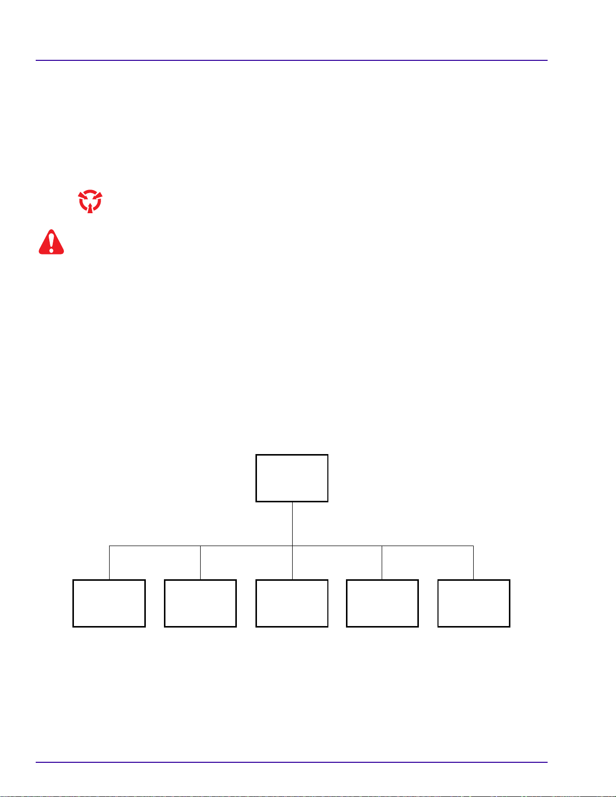
COMPLETE
BINDER
981903
OPERATOR
MANUAL
SITE SPECS
981157
INSTALLATION
INSTRUCTIONS
981900
SERVICE
MANUAL
981901981799
PARTS LIST
981902
H112_9003BC
2 September 1996 – 981901
Page 3

Table of Contents
Description Page
Introduction . . . . . . . . . . . . . . . . . . . . . . . . . . . . . . . . . . . . . . . . . . . . . . . . . . . . . . . . . . . . 1-1
Electrostatic Discharge . . . . . . . . . . . . . . . . . . . . . . . . . . . . . . . . . . . . . . . . . . . . . . . 1-1
Description . . . . . . . . . . . . . . . . . . . . . . . . . . . . . . . . . . . . . . . . . . . . . . . . . . . . . . . . . 1-1
Special Tools Needed. . . . . . . . . . . . . . . . . . . . . . . . . . . . . . . . . . . . . . . . . . . . . . . . . 1-1
Specifications and Data . . . . . . . . . . . . . . . . . . . . . . . . . . . . . . . . . . . . . . . . . . . . . . . 1-1
Adjustments and Replacements . . . . . . . . . . . . . . . . . . . . . . . . . . . . . . . . . . . . . . . . . . . . 2-1
FEED SHELF . . . . . . . . . . . . . . . . . . . . . . . . . . . . . . . . . . . . . . . . . . . . . . . . . . . . . . . 2-1
DETECTOR SWITCHES . . . . . . . . . . . . . . . . . . . . . . . . . . . . . . . . . . . . . . . . . . . . . . 2-2
CROSSOVER ASSEMBLIES . . . . . . . . . . . . . . . . . . . . . . . . . . . . . . . . . . . . . . . . . . 2-4
RACKS . . . . . . . . . . . . . . . . . . . . . . . . . . . . . . . . . . . . . . . . . . . . . . . . . . . . . . . . . . . 2-5
Main Drive . . . . . . . . . . . . . . . . . . . . . . . . . . . . . . . . . . . . . . . . . . . . . . . . . . . . . . . . . 2-18
DRYER HEATER . . . . . . . . . . . . . . . . . . . . . . . . . . . . . . . . . . . . . . . . . . . . . . . . . . . . 2-24
Plumbing . . . . . . . . . . . . . . . . . . . . . . . . . . . . . . . . . . . . . . . . . . . . . . . . . . . . . . . . . . 2-29
Overview. . . . . . . . . . . . . . . . . . . . . . . . . . . . . . . . . . . . . . . . . . . . . . . . . . . . . . . 1-1
Preventive Measures . . . . . . . . . . . . . . . . . . . . . . . . . . . . . . . . . . . . . . . . . . . . . 1-1
Film Sizes and Direction of Film Feed . . . . . . . . . . . . . . . . . . . . . . . . . . . . . . . . 1-2
Speed of the PROCESSOR and Developer Temperature . . . . . . . . . . . . . . . . 1-2
Basic Theory of Operation . . . . . . . . . . . . . . . . . . . . . . . . . . . . . . . . . . . . . . . . . 1-3
Wash Water . . . . . . . . . . . . . . . . . . . . . . . . . . . . . . . . . . . . . . . . . . . . . . . . 1-3
DRYER . . . . . . . . . . . . . . . . . . . . . . . . . . . . . . . . . . . . . . . . . . . . . . . . . . . . 1-3
Films and Chemicals. . . . . . . . . . . . . . . . . . . . . . . . . . . . . . . . . . . . . . . . . . 1-3
REPLENISHMENT PUMP . . . . . . . . . . . . . . . . . . . . . . . . . . . . . . . . . . . . . 1-3
MAIN DRIVE MOTOR. . . . . . . . . . . . . . . . . . . . . . . . . . . . . . . . . . . . . . . . . 1-3
BLOWER MOTOR . . . . . . . . . . . . . . . . . . . . . . . . . . . . . . . . . . . . . . . . . . . 1-3
Capacity of the TANKS with the RACKS Installed . . . . . . . . . . . . . . . . . . . . . . . 1-3
Adjustment of the FEED SHELF . . . . . . . . . . . . . . . . . . . . . . . . . . . . . . . . . . . . 2-1
Replacement of the PROTECTIVE MATERIAL . . . . . . . . . . . . . . . . . . . . . . . . . 2-1
Adjustment of the DETECTOR SWITCHES . . . . . . . . . . . . . . . . . . . . . . . . . . . 2-2
Replacement of the DETECTOR SWITCHES . . . . . . . . . . . . . . . . . . . . . . . . . . 2-3
Adjustment for Squareness . . . . . . . . . . . . . . . . . . . . . . . . . . . . . . . . . . . . . . . . 2-4
Adjustment for Squareness . . . . . . . . . . . . . . . . . . . . . . . . . . . . . . . . . . . . . . . . 2-5
Adjustment of the Tension on the DRIVE CHAIN . . . . . . . . . . . . . . . . . . . . . . . 2-6
Replacement of the DRIVE CHAIN . . . . . . . . . . . . . . . . . . . . . . . . . . . . . . . . . . 2-6
Adjustment of the GUIDE SHOES in the DEVELOPER RACK . . . . . . . . . . . . . 2-7
Adjustment of the SMOOTH GUIDE SHOES in the DEVELOPER RACK . . . . 2-9
Adjustment of a TURNAROUND ASSEMBLY for Squareness . . . . . . . . . . . . 2-11
Replacement of a ROLLER in a TURNAROUND ASSEMBLY . . . . . . . . . . . . . 2-12
Replacement of the DRIVE ROLLER in the Developer RACK . . . . . . . . . . . . . 2-14
Replacement of the Resilient ROLLERS in the Fixer and Wash RACKS . . . . . 2-15
Adjustment of the DRYER RACK for Squareness . . . . . . . . . . . . . . . . . . . . . . 2-16
Replacement of the DRIVE ROLLER in the DRYER RACK . . . . . . . . . . . . . . . 2-17
Adjustment of the Main DRIVE CHAIN . . . . . . . . . . . . . . . . . . . . . . . . . . . . . . . 2-18
Alignment of the MAIN DRIVE MOTOR . . . . . . . . . . . . . . . . . . . . . . . . . . . . . . 2-19
Replacement of the Main DRIVE SHAFT, WORM GEARS, or
BEARING BLOCKS . . . . . . . . . . . . . . . . . . . . . . . . . . . . . . . . . . . . . . . . . . . . 2-20
Adjustment of the Speed of the MAIN DRIVE MOTOR . . . . . . . . . . . . . . . . . . . 2-22
Adjustment of the Temperature of the DRYER . . . . . . . . . . . . . . . . . . . . . . . . . 2-24
Replacement of the BLOWER ASSEMBLY . . . . . . . . . . . . . . . . . . . . . . . . . . . 2-25
Replacement of the DRYER HEATER or the HEATER CORE . . . . . . . . . . . . . 2-27
Adjustment of the Developer Temperature . . . . . . . . . . . . . . . . . . . . . . . . . . . . 2-29
Adjustment of the Developer Temperature METER . . . . . . . . . . . . . . . . . . . . . 2-31
Removal of the Developer Temperature METER . . . . . . . . . . . . . . . . . . . . . . . 2-33
Installation of the Developer Temperature METER . . . . . . . . . . . . . . . . . . . . . . 2-34
Replacement of the DEVELOPER HEATER . . . . . . . . . . . . . . . . . . . . . . . . . . . 2-36
981901 – September 1996 3
Page 4

Replacement of the DEVELOPER OVER-TEMPERATURE THERMOSTAT . . 2-37
Replacement of the DEVELOPER THERMISTOR . . . . . . . . . . . . . . . . . . . . . . 2-38
Replacement of the HEAT EXCHANGERS . . . . . . . . . . . . . . . . . . . . . . . . . . . 2-40
Replacement of the RECIRCULATION PUMP . . . . . . . . . . . . . . . . . . . . . . . . . 2-42
Replacement of the O-RING . . . . . . . . . . . . . . . . . . . . . . . . . . . . . . . . . . . . . . . 2-43
Replacement of a REPLENISHMENT PUMP . . . . . . . . . . . . . . . . . . . . . . . . . . 2-44
Adjustment of the REPLENISHMENT PUMPS . . . . . . . . . . . . . . . . . . . . . . . . . 2-45
Adjustment of the Replenishment Flow Rates . . . . . . . . . . . . . . . . . . . . . . . . . 2-46
Periodic Maintenance . . . . . . . . . . . . . . . . . . . . . . . . . . . . . . . . . . . . . . . . . . . . . . . . . . . . 3-1
General Information . . . . . . . . . . . . . . . . . . . . . . . . . . . . . . . . . . . . . . . . . . . . . . . . . . 3-1
Roller Transport . . . . . . . . . . . . . . . . . . . . . . . . . . . . . . . . . . . . . . . . . . . . . . . . . . . . . 3-3
DETECTOR SWITCHES and DETECTOR CROSSOVER ASSEMBLY . . . . . 3-3
CROSSOVER ASSEMBLIES . . . . . . . . . . . . . . . . . . . . . . . . . . . . . . . . . . . . . . 3-4
RACK ASSEMBLIES and ROLLERS . . . . . . . . . . . . . . . . . . . . . . . . . . . . . . . . 3-5
TURNAROUND ASSEMBLIES . . . . . . . . . . . . . . . . . . . . . . . . . . . . . . . . . . . . . 3-6
DRIVE CHAIN and SPRINGS . . . . . . . . . . . . . . . . . . . . . . . . . . . . . . . . . . . . . . 3-7
DRYER. . . . . . . . . . . . . . . . . . . . . . . . . . . . . . . . . . . . . . . . . . . . . . . . . . . . . . . . . . . . 3-8
Main Drive . . . . . . . . . . . . . . . . . . . . . . . . . . . . . . . . . . . . . . . . . . . . . . . . . . . . . . . . . 3-9
Plumbing . . . . . . . . . . . . . . . . . . . . . . . . . . . . . . . . . . . . . . . . . . . . . . . . . . . . . . . . . . 3-10
General . . . . . . . . . . . . . . . . . . . . . . . . . . . . . . . . . . . . . . . . . . . . . . . . . . . . . . . 3-10
RECIRCULATION PUMPS . . . . . . . . . . . . . . . . . . . . . . . . . . . . . . . . . . . . . . . . 3-11
DEVELOPER FILTER and Temperataure . . . . . . . . . . . . . . . . . . . . . . . . . . . . 3-12
Chemical Replenishment . . . . . . . . . . . . . . . . . . . . . . . . . . . . . . . . . . . . . . . . . 3-12
INTERLOCK SWITCH . . . . . . . . . . . . . . . . . . . . . . . . . . . . . . . . . . . . . . . . . . . . . . . . 3-13
Correcting Difficulties . . . . . . . . . . . . . . . . . . . . . . . . . . . . . . . . . . . . . . . . . . . . . . . . . . . . 4-1
Diagrams . . . . . . . . . . . . . . . . . . . . . . . . . . . . . . . . . . . . . . . . . . . . . . . . . . . . . . . . . . . . . 5-1
Publication History . . . . . . . . . . . . . . . . . . . . . . . . . . . . . . . . . . . . . . . . . . . . . . . . . . . . . . 6-1
4 September 1996 – 981901
Page 5

Section 1: Introduction
Electrostatic Discharge
Overview
ESD - electrostatic discharge - is a primary source of:
• product downtime
• lost productivity
• costly repairs
While one cannotfeelastaticchargeoflessthan3,500volts,asfewas30voltscandamageordestroy
essential components in electronic equipment.
Preventive Measures
• Always look for an ESD warning label before doing any procedure involving static-sensitive
components such as CIRCUIT BOARDS. All static-sensitive components are marked with bright
graphic labels, which frequently include instructions. Follow all label instructions.
• Wear agroundingstrap when handling static-sensitive components. Always make certain that the
clip remains attached to a properly grounded, unpainted, clean surface.
• Repair static-sensitive components at an ESD-protected work station or use a portablegrounding
mat. For help in setting up an ESD-protected work station, contact your Kodak representative.
• When moving static-sensitive components from one area to another, insert and transport the
components in ESD-protective packaging. Transparent antistatic bags are available from avariety
of manufacturers and will help shield components from ESD damage.
Introduction
Description
The
Kodak
mammography. This self-threading roller-transport processor has a replenishment system, a developer solution
filter, recirculation of the developer and fixer solutions, and an automatic standby feature.
M35-M and M35A-M
X-Omat
PROCESSORS are designed to process medical x-ray sheet film used for
Special Tools Needed
The following special tools are necessary for some of the service procedures in this manual.
• TL-2244 Motor Oil, 1-oz Tube
• TL-2324 Motor Oil, 12-oz Tube
• TL-1481 Potentiometer Adjusting Tool
• TL-3230 Sealant
• TL-4802 Thermometer
• 1C7639 Turnaround Adjustment Tool
Specifications and Data
Note
Publication No. 981157 contains the site specifications forthe
Kodak
M35-M and M35A-M
X-Omat
PROCESSORS.
981901 – September 1996 1–1
Page 6
SERVICE MANUAL
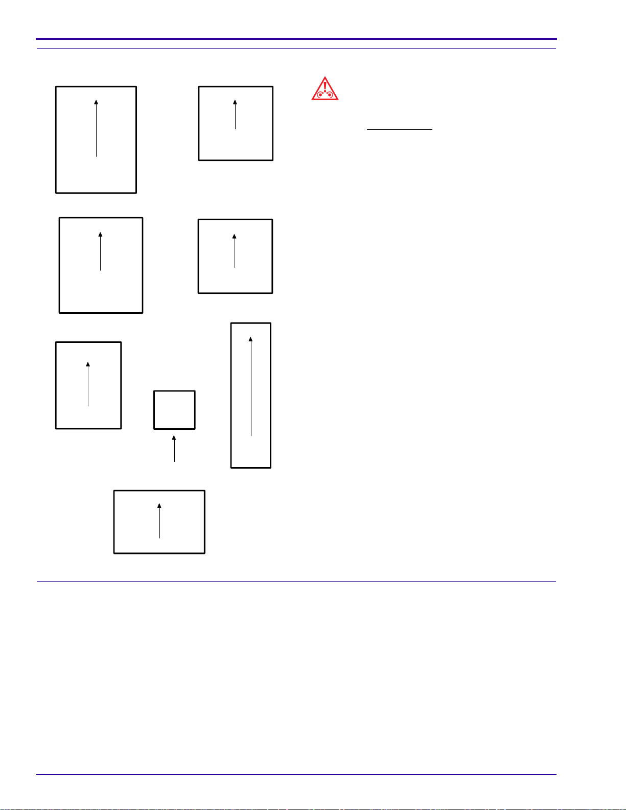
Film Sizes and Direction of Film Feed
1 each
35 x 43 cm
or
14 x 17 in.
1 each
24 x 30 cm
or
10 x 12 in.
2 each
1 each
35 x 35 cm
or
14 x 14 in.
1 each
24 x 24 cm
1 each
Caution
• Process only sheet film in the
M35A-M
X-Omat
PROCESSORS.
• Feeding other than sheet film may result in
transport failures and damage to the processing
RACKS.
The illustration shows the correct sizes of film to use.
Feed mammography film into the PROCESSOR with
the emulsion up and in the direction of the arrows. A
film feed signal will sound 8 seconds after the trailing
edge of the sheet of film leaves the DETECTOR
ROLLERS.
Kodak
M35-M and
2 each
10 x 10 cm
18 x 24 cm
or
4 x 4 in.
18 x 43 cm
1 each
11 x 14 in.
H112_9004CC
Speed of the PROCESSOR and Developer Temperature
Extended Mode: Use this mode for mammography films that the manufacturer has specified are suitable for
extended cycle processing. The transport speed for this mode is 50 cm (191⁄2) in.) per minute or 3 minutes and
23 seconds ± 2 sec drop time (dry to dry) for a 24 cm (10 in.) sheet of film. The developer temperature is 35˚C ±
0.3˚C (95.0˚F ± 0.5˚F). The development time is approximately 50 seconds and is based on using
Film.
Standard Mode: The Standard Mode is suitable for all mammography films. The transport speed for this mode is
76 cm (30 in.) per minute or 2 minutes and 15 seconds ± 2 sec drop time (dry to dry) for a 24 cm (10 in.) sheet of
film. The developer temperature is 33.3˚C ± 0.3˚C (92.0˚F ± 0.5˚F). The development time is approximately 33
seconds and is based on using
Kodak Min-R
M Film.
The temperature of the fixer is not adjustable.
Kodak Min-R
E
1–2 September 1996 – 981901
Page 7

Basic Theory of Operation
Wash Water
Thewaterforwashingthe film comes from thecustomer'swatersupply. The FLOW CONTROLVALVE
regulates the usage at approximately 1 litre (1⁄4 gallon) per minute.
DRYER
The PROCESSOR has a roller transportdryerwithslotted AIR TUBES. A THERMOSTATcontrolsthe
temperature from 46 - 65˚C (115 - 150˚F).
Films and Chemicals
The KODAK
Kodak
RP
The RECIRCULATION PUMPforthedeveloperandthefixerconsistsofathermallyprotectedMOTOR
that operates two magnetic, centrifugal pumps.
REPLENISHMENT PUMP
The replenishment system uses a positive displacement BELLOWS PUMP, designed for accurate
delivery of replenishment solutions regardless of the solution level in the REPLENISHMENT TANKS.
M35-M and M35A-M
X-Omat
Introduction
X-OMAT PROCESSORS accept film that can be processed in
Chemicals.
MAIN DRIVE MOTOR
The MAIN DRIVE MOTOR is an enclosed gearhead motor with an automatic thermal overload
protector.
BLOWER MOTOR
The BLOWER MOTOR is equipped with an automatic thermal overload protector.
Capacity of the TANKS with the RACKS Installed
The developer, fixer, and wash TANKS each contain 7.8 litres (2.07 gallons).
981901 – September 1996 1–3
Page 8

SERVICE MANUAL
1–4 September 1996 – 981901
Page 9
Section 2: Adjustments and Replacements
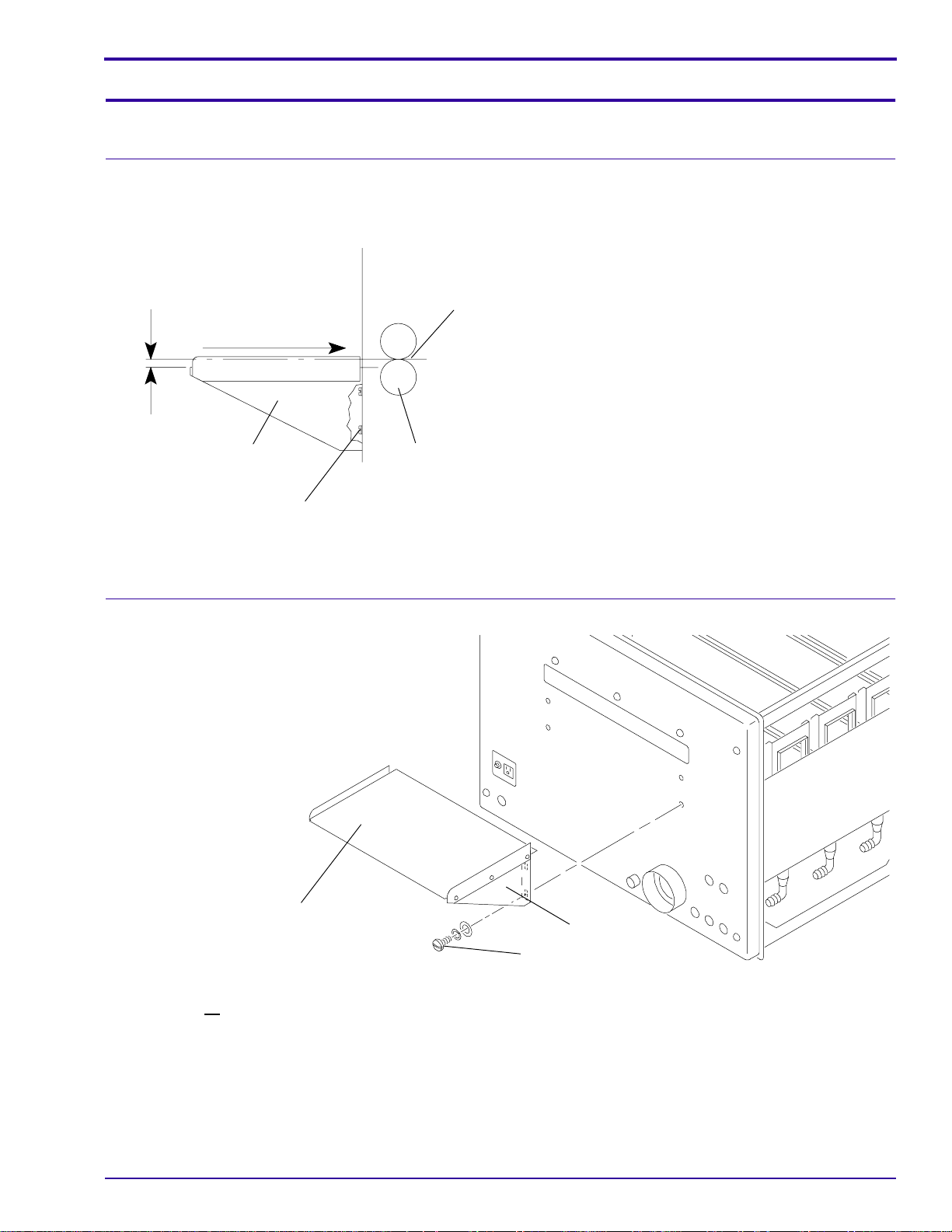
FEED SHELF
Adjustment of the FEED SHELF
[1] Adjust the height of the FEED SHELF to
approximately1.5 mm (0.06 or 1/16 in.)belowthe
NIPoftheDETECTORCROSSOVERROLLERS.
1.5 mm
(0.06 in.)
film entry path
FEED
SHELF
SCREW (4)
NIP
DETECTOR
CROSSOVER
ROLLERS
H112_0090ACB
H112_0090AA
(a) Loosen the 4 SCREWS.
(b) Adjust the FEED SHELF for the correct
(c) Insert a sheet of35 x 43 cm(14 x17 in.) film
[2] Use the edges of the film to align the FILM SHELF
withtheDETECTORCROSSOVERROLLERSfor
squareness.
[3] Tighten the 4 SCREWS.
Adjustments and Replacements
height by moving the FEED SHELF up or
down.
into the NIP of the DETECTOR
CROSSOVER ROLLERS.
Replacement of the PROTECTIVE MATERIAL
PROTECTIVE
H112_0113BCA
H112_0113BA
MATERIAL
SCREW (4)
[1] Remove the 4 SCREWS and the FEED SHELF.
[2] Remove all of the existing PROTECTIVE MATERIAL and adhesive from the FEED SHELF.
[3] Clean the FEED SHELF with a damp sponge.
[4] Check that the FEED SHELF is dry before installing the PROTECTIVE MATERIAL.
[5] Install the new PROTECTIVE MATERIAL.
[6] Install the FEED SHELF and adjust if necessary. See the above procedure.
FEED SHELF
981901 – September 1996 2–1
Page 10
SERVICE MANUAL
DETECTOR SWITCHES
Adjustment of the DETECTOR SWITCHES
DETECTOR
ROLLER
DETECTOR
SWITCH (2)
SCREW
ROCKER
ARM
1.6 mm
(0.06 in.)
MAGNET (2)
ROCKER ARM
DETECTOR
SWITCH (2)
H112_0112BCA
H112_0112BA
Caution
Moving parts.
[1] Remove the TOP COVER.
[2] Check the DEVELOPER RACK and the DETECTOR CROSSOVER ASSEMBLY for squareness. See
Pages 2–4 and 2–5.
[3] Install the DEVELOPER RACK and the DETECTOR CROSSOVER ASSEMBLY.
[4] Set the clearance between the MAGNET and theDETECTORSWITCH on the drive side to 1.6 mm (0.06 or 1/
16 in.).
[5] Check the clearance between the MAGNET and the DETECTOR SWITCH:
(a) Energize the PROCESSOR.
(b) Lift the top DETECTOR ROLLER.
(c) Insert a 5 x 7 in. sheet of film.
(d) Move the drive side DETECTOR SWITCH until the REPLENISHMENT PUMP activates.
(e) Check that the REPLENISHMENT PUMP stops within 3 seconds after you remove the sheet of film.
[6] If necessary, adjust the clearance between the MAGNET and the DETECTOR SWITCH.
(a) Loosen the SCREW.
(b) Move the ROCKER ARM.
(c) Tighten the SCREW.
[7] Do Steps 4 - 6 to adjust the DETECTOR SWITCH on the nondrive side.
[8] Install the TOP COVER.
[9] Check that the REPLENISHMENT PUMP does not operate unless you feed film.
2–2 September 1996 – 981901
Page 11
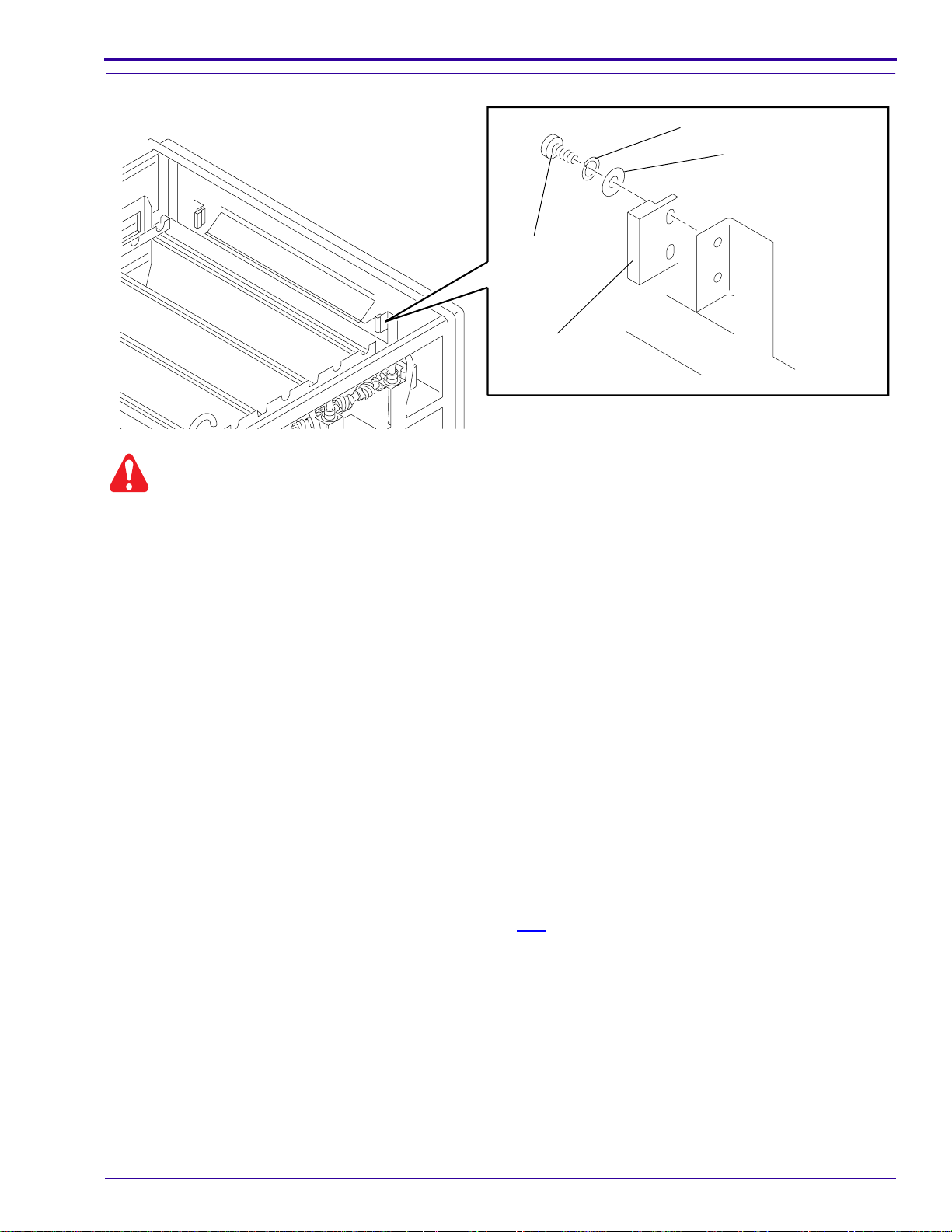
Replacement of the DETECTOR SWITCHES
Warning
Dangerous voltage.
SCREW (2)
DETECTOR
SWITCH
Adjustments and Replacements
LOCK WASHER (2)
WASHER (2)
H112_0067BCA
H112_0067BA
[1] Disconnect the main power.
[2] Remove:
• 2 SCREWS
• 2 LOCK WASHERS
• 2 WASHERS
• WIRE TIES, not shown
[3] Disconnect the SWITCH CABLE from the ELECTRICAL BOX.
[4] Connect the new SWITCH CABLE.
[5] Install:
• new DETECTOR SWITCH
• 2 WASHERS
• 2 LOCK WASHERS
• 2 SCREWS
• new WIRE TIES
[6] Connect the main power.
[7] If necessary, do the adjustment procedure. See Page 2–2.
981901 – September 1996 2–3
Page 12
SERVICE MANUAL
CROSSOVER ASSEMBLIES
Adjustment for Squareness
TIE ROD
SIDE
PLATE
GUIDE SHOE
SCREW (2)
TIE ROD
long edge
GUIDE
SHOE
NUT
SIDE PLATE
NUT
H112_0056BCC
H112_0056BA
Note
Use this procedure to check the squareness of any of
the CROSSOVER ASSEMBLIES.
[1] Remove the CROSSOVER ASSEMBLY from the
PROCESSOR.
[2] Place the CROSSOVER ASSEMBLY on a
smooth, flat surface.
[3] Loosen the 2 NUTS on the 2 TIE RODS.
[4] Check that the 2 SIDE PLATES touch the flat
surface evenly.
[5] Tighten the 2 NUTS.
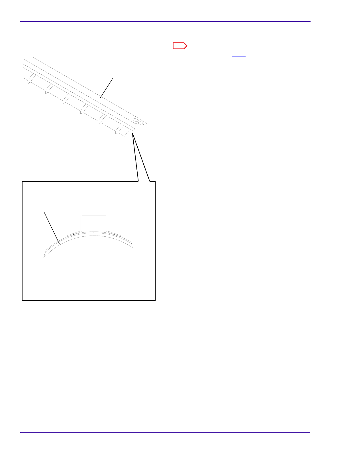
Installation of a New GUIDE SHOE
[6] Removetheexisting GUIDESHOESCREWSand
the GUIDE SHOE.
[7] Install the new GUIDE SHOE, with the long edge
long edge
in the direction of film travel.
[8] Install the 2 GUIDE SHOE SCREWS.
Note
The GUIDE SHOES have no adjustment procedures.
H112_0220CCA
H112_0220CA
2–4 September 1996 – 981901
Page 13
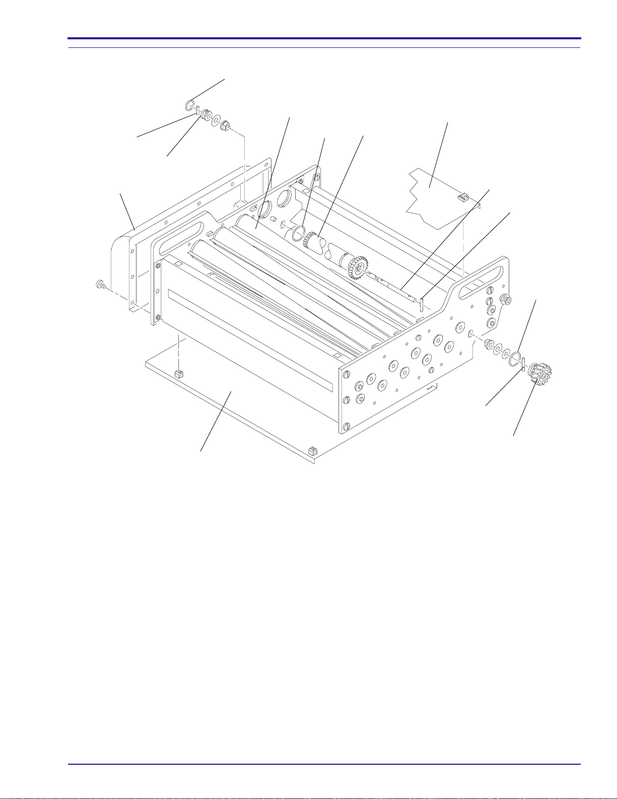
RACKS
H112_0017AC
H112_0017ACB
SCREWS
2 TIE RODS
SIDE PLATE
TIE ROD
SCREW (2)
SIDE PLATE
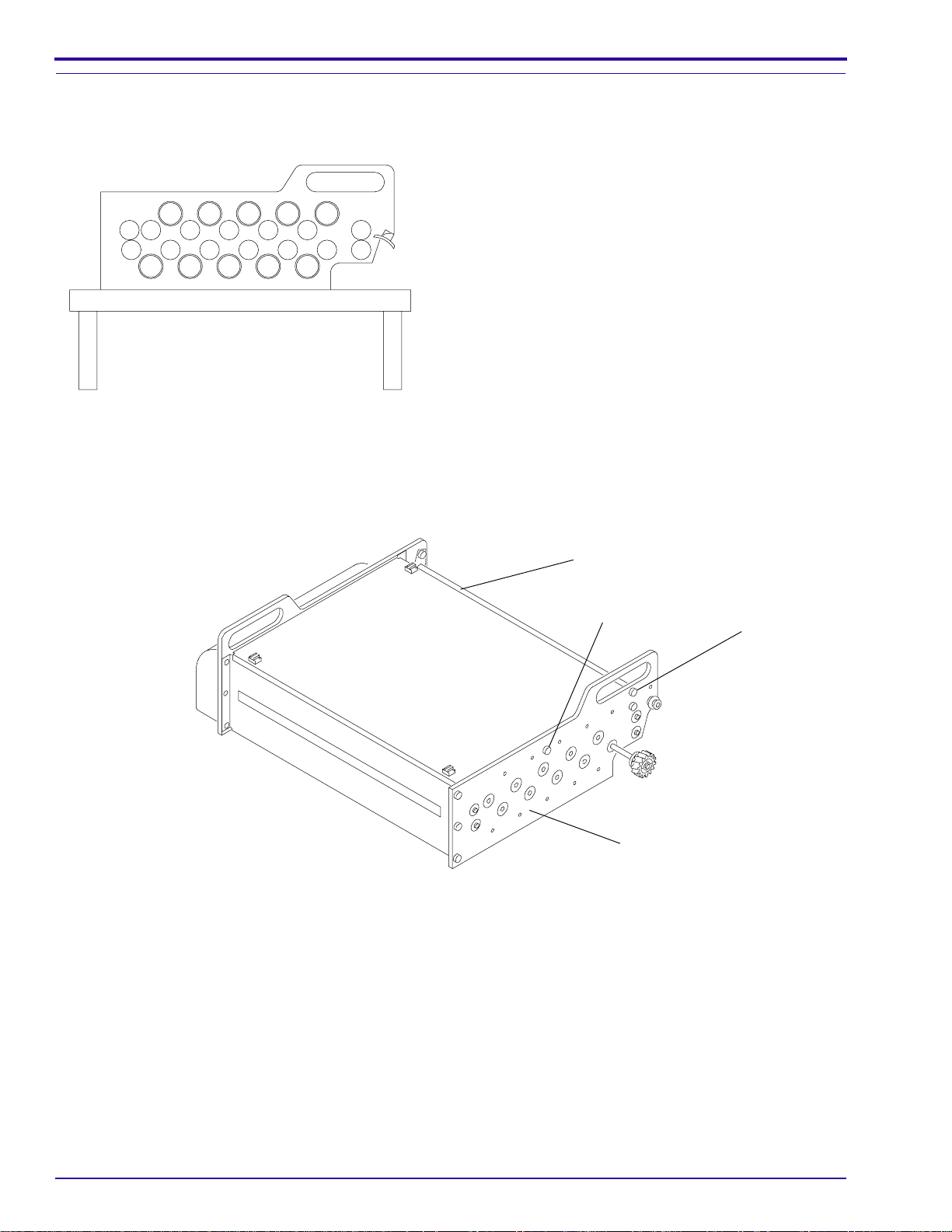
Adjustment for Squareness
smooth, flat surface
Adjustments and Replacements
Note
Use this procedure to check the squareness of any of
the RACKS.
[1] Remove the RACK from the PROCESSOR.
[2] Place the RACK on a smooth, flat surface.
[3] Loosen the SCREWS on the ends of the 3 TIE
RODS.
[4] Check that the 2 SIDE PLATES touch the flat
surface evenly.
[5] Tighten the SCREWS.
H112_0110AA
981901 – September 1996 2–5
Page 14
SERVICE MANUAL
Adjustment of the Tension on the DRIVE CHAIN
HOOK
SIDE PLATE
HOLDING
SCREW (4)
TURNAROUND
ASSEMBLY
LINK
DRIVE
GEAR
ADJUSTING
SCREW (4)
[1] Check that the DRIVE CHAIN iswet with solution.
[2] To assure that the DRIVE CHAIN is the correct
length, check that the RACK is at approximately
the same temperature as the solutions in the
tanks.
[3] Loosen the 4 HOLDING SCREWS.
[4] Allow gravity to provide full tension on the
TURNAROUNDASSEMBLY byholding theRACK
above the work surface.
[5] Rotate the DRIVE GEAR one full rotation.
[6] Tighten the 2 HOLDING SCREWS on the drive
side first.
[7] Place the RACK on the work surface.
[8] On the drive side of the RACK, tighten the
2 ADJUSTING SCREWS until both SCREWS
make contact with the SIDE PLATE of the
TURNAROUND ASSEMBLY.
[9] Loosen the 2 HOLDING SCREWS on the drive
side.
[10] Rotate the 2 ADJUSTING SCREWS on the drive
side counterclockwise one full rotation.
[11] Rotate the DRIVE GEAR one full rotation.
[12] Tighten the 2 HOLDING SCREWS on the drive
side.
[13] On the nondrive side of the RACK, rotate the
2 ADJUSTING SCREWS until the distance
betweenthe2 SIDE PLATES onthenondriveside
is the same distance as the distance betweenthe
2 SIDE PLATES on the drive side.
[14] Assemble the PROCESSOR and check that it
operates correctly.
DRIVE CHAIN
H112_0109CCA
H112_0109CA
Replacement of the DRIVE CHAIN
[1] To open the existing DRIVE CHAIN, insert a screwdriver under theHOOKS of aLINK. Ifnecessary, rotatethe
screwdriver.
[2] Attach the new DRIVE CHAIN to the existing DRIVE CHAIN with the HOOKS in the direction of travel and the
openings of the LINKS outward. See the figure above.
[3] Pull the existing DRIVE CHAIN through the RACK until the new DRIVE CHAIN is in the correct position.
[4] Disconnect the existing DRIVE CHAIN from the new DRIVE CHAIN.
[5] Connect the ends of the new DRIVE CHAIN.
[6] Adjust the DRIVE CHAIN. See the procedure above.
2–6 September 1996 – 981901
Page 15

Adjustments and Replacements
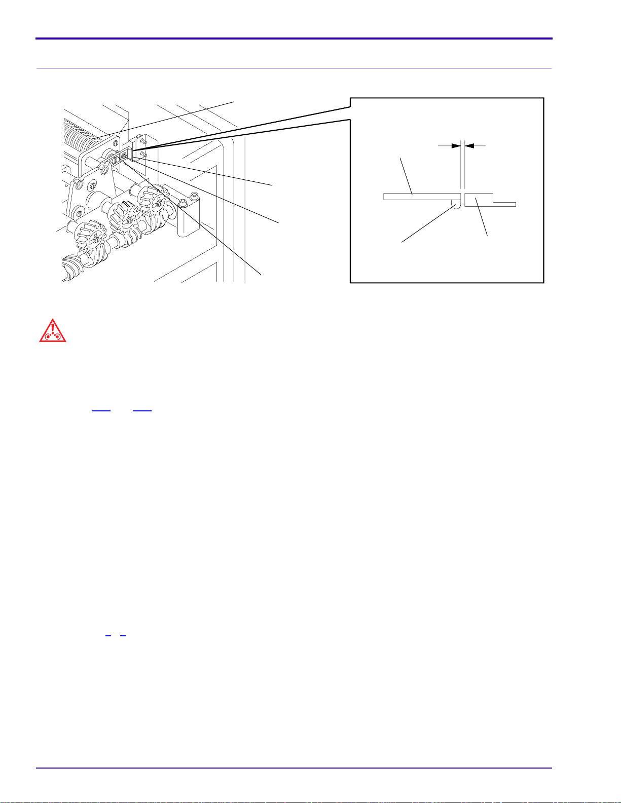
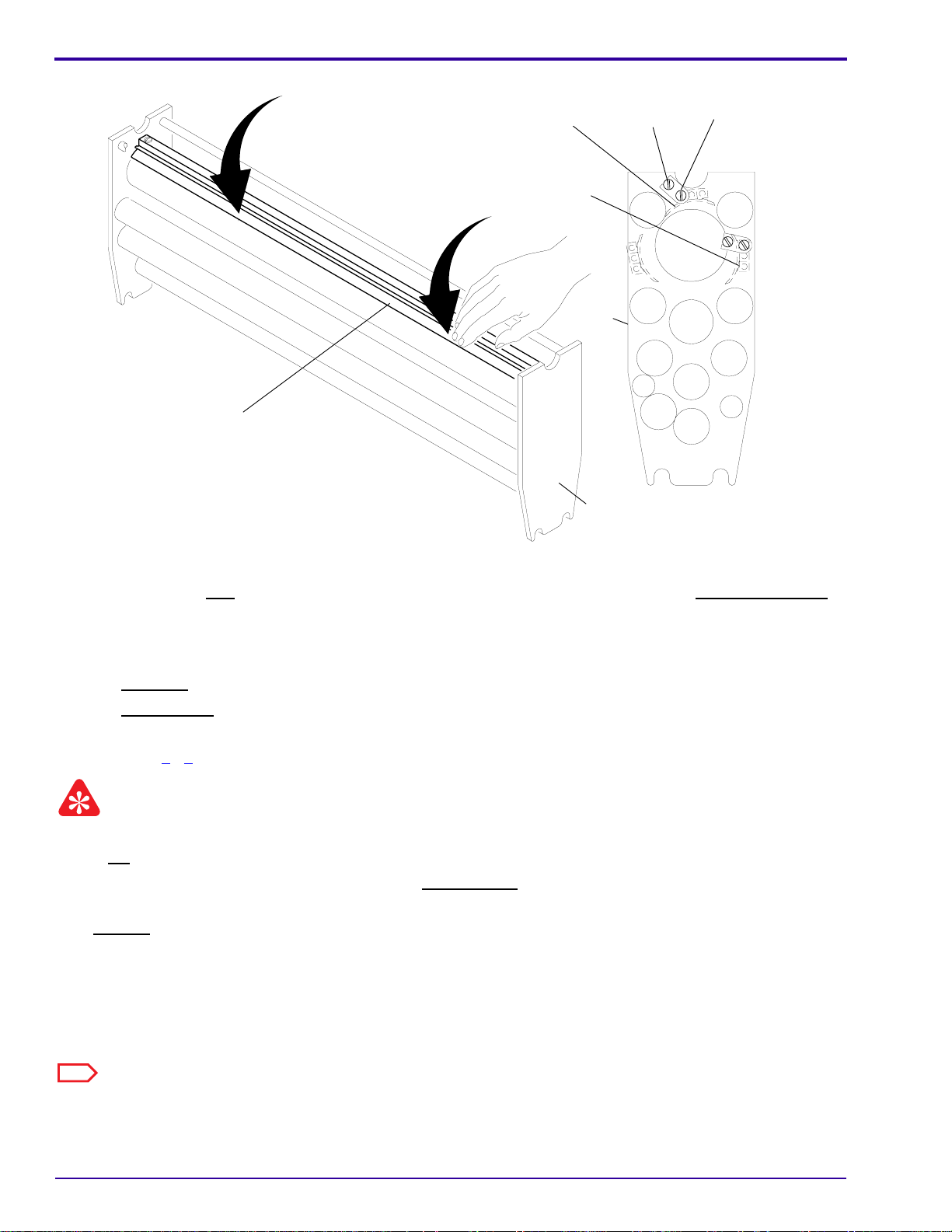
Adjustment of the GUIDE SHOES in the DEVELOPER RACK
Important
Dothisadjustmentonlyifthecustomerprocesses double-emulsion film. The GUIDE SHOES are presetatthefactory
for a gap of 0.020 in. for single-emulsion film. For a gap of 0.040 in. necessary for double-emulsion film, feed
2 TURNAROUND ADJUSTMENT TOOLS together through the DEVELOPER RACK.
[1] Remove the DEVELOPER RACK from the PROCESSOR.
[2] Do these procedures before you adjust the GUIDE SHOES:
a. Adjust the DEVELOPER RACK for squareness, on Page 2–5
b. Adjust the tension on the DRIVE CHAIN, on Page 2–6
c. Adjust the TURNAROUND ASSEMBLY for squareness, on Page 2–11
[3] For access to the GUIDE SHOE BRACKET SCREWS, release the SPRING on the drive side of the
DEVELOPER RACK.
[4] Loosen the 4 GUIDE SHOE BRACKET SCREWS and the 4 LOCKING SCREWS for the ENTRANCE GUIDE
SHOE and the BOTTOM GUIDE SHOE in the TURNAROUND ASSEMBLY.
[5] Feed 2 TURNAROUND ADJUSTMENT TOOLS 1C7639 into the DEVELOPER RACK until the leading edges
of the TOOLS are in the EXIT GUIDE SHOE. See the figure below.
LOCKING
EXIT
GUIDE SHOE
SCREW (4)
TURNAROUND
ADJUSTMENT
TOOL
1C7639
TURNAROUND
ADJUSTMENT
TOOL
1C7639
ENTRANCE
GUIDE
SHOE
LOCKING
SCREW
DOUBLE
LOCK
MOUNTING
PLATE
1C7632
GUIDE SHOE
BRACKET
SCREW (4)
BOTTOM GUIDE
SHOE ASSY
1C7635
SPRING
TURNAROUND
ASSEMBLY
GUIDE SHOE
BRACKET SCREW
(4)
LOCKING SCREW
(4)
H112_0198DCA
drive
side
H112_0198DA
981901 – September 1996 2–7
Page 16
SERVICE MANUAL
Aligning the Edges of the GUIDE SHOES in the DEVELOPER RACK
press here
long edge
of GUIDE SHOE
BOTTOM
GUIDE
SHOE
ENTRANCE
press here
GUIDE
SHOE
exit
side
LOCKING
SCREW
GUIDE SHOE
BRACKET
SCREW
nondrive
side
H112_0218HCA
H112_0218HA
[6] Place the DEVELOPER RACK with the exit side on the work surface.
[7] Pressing on the long edge of the ENTRANCE GUIDE SHOE approximately 6 cm (3 in.) from the drive side,
tighten the drive side GUIDE SHOE BRACKET SCREW.
[8] Press on the nondrive side of the long edge, and tighten the nondrive GUIDE SHOE BRACKET SCREW.
[9] Tighten:
a. drive side LOCKING SCREW
b. nondrive side LOCKING SCREW
[10] Turn the DEVELOPER RACK upside down on the work surface. See the figure above.
[11] Do Steps 7 - 9 for the BOTTOM GUIDE SHOE.
Important
•Donot continue feeding the TURNAROUND ADJUSTMENT TOOL to remove it from the DEVELOPER RACK.
• The EXIT GUIDE SHOE is preset at the factory. Do not adjust.
[12] Reverse the DRIVE GEAR to remove the TURNAROUND ADJUSTMENT TOOL from the DEVELOPER RACK.
[13] Install the SPRING.
[14] Check the DEVELOPER RACK and the TURNAROUND ASSEMBLY for squareness.
[15] Install the DEVELOPER RACK in the PROCESSOR.
[16] Energize the PROCESSOR and check for correct operation.
Note
Adjusting the GUIDE SHOES in the WASH and FIXER RACKS is not necessary.
2–8 September 1996 – 981901
Page 17
Adjustments and Replacements
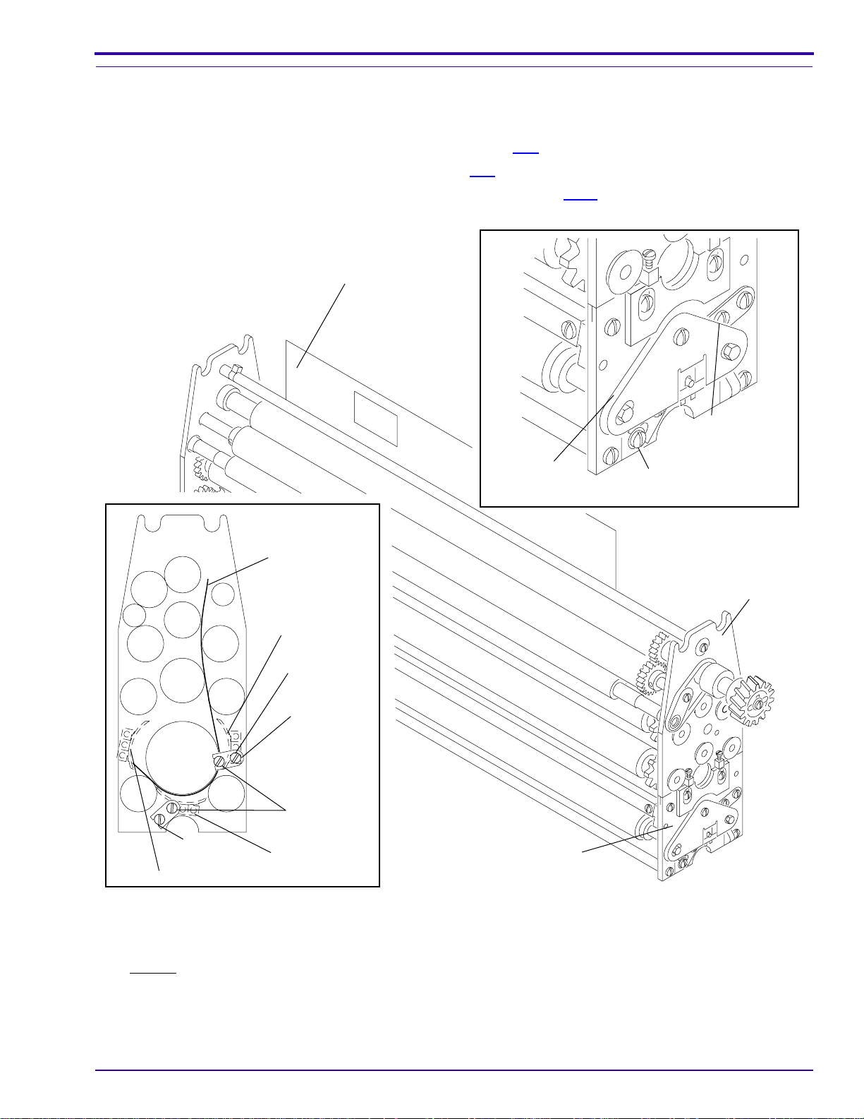
Adjustment of the SMOOTH GUIDE SHOES in the DEVELOPER RACK
[1] Remove the DEVELOPER RACK from the PROCESSOR.
[2] Do these 3 procedures before you adjust the GUIDE SHOES:
a. Adjust the DEVELOPER RACK for squareness, on Page 2–5
b. Adjust the tension on the DRIVE CHAIN, on Page 2–6
c. Adjust the TURNAROUND ASSEMBLY for squareness, on Page 2–11
TURNAROUND
ADJUSTMENT
TOOL
1C7639
SPRING
4 LOCKING SCREWS
4 GUIDE SHOE
BRACKET SCREWS
TURNAROUND
ADJUSTMENT
4 LOCKING
EXIT
GUIDE SHOE
SCREWS
TOOL
1C7639
ENTRANCE
GUIDE
SHOE
LOCKING
SCREW
DOUBLE
LOCK
MOUNTING
PLATE
4 GUIDE SHOE
BRACKET
SCREWS
BOTTOM GUIDE
SHOE ASSY
TURNAROUND
ASSEMBLY
drive
side
H112_0198DCB
H112_0198DA
[3] For access to the GUIDE SHOE BRACKET SCREWS, release the SPRING on the drive side of the
DEVELOPER RACK.
[4] Loosen the 4 GUIDE SHOE BRACKET SCREWS and the 4 LOCKING SCREWS for the ENTRANCE GUIDE
SHOE and the BOTTOM GUIDE SHOE in the TURNAROUND ASSEMBLY.
[5] Feed the TURNAROUND ADJUSTMENT TOOL 1C7639 into the DEVELOPERRACK until theleadingedgeof
the TOOL is in the EXIT GUIDE SHOE. See the figure.
981901 – September 1996 2–9
Page 18
SERVICE MANUAL
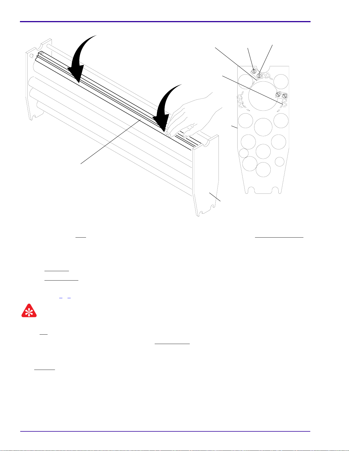
Aligning the Edges of the New GUIDE SHOES
press here
long edge
of GUIDE SHOE
BOTTOM
ENTRANCE
press here
GUIDE
SHOE
GUIDE
SHOE
exit
side
LOCKING
SCREW
GUIDE SHOE
BRACKET
SCREW
nondrive
side
H112_0218HCA
H112_0218HA
[6] Place the DEVELOPER RACK with the exit side on the work surface.
[7] Pressing on the long edge of the ENTRANCE GUIDE SHOE approximately 6 cm (3 in.) from the drive side,
tighten the drive side GUIDE SHOE BRACKET SCREW.
[8] Press on the nondrive side of the long edge, and tighten the nondrive GUIDE SHOE BRACKET SCREW.
[9] Tighten:
a. drive side LOCKING SCREW
b. nondrive side LOCKING SCREW
[10] Turn the DEVELOPER RACK upside down on the work surface. See the figure.
[11] Do Steps 7 - 9 for the BOTTOM GUIDE SHOE.
Important
•Donot continue feeding the TURNAROUND ADJUSTMENT TOOL to remove it from the DEVELOPER RACK.
• The EXIT GUIDE SHOE is preset at the factory. Do not adjust.
• Adjusting the GUIDE SHOES in the WASH and FIXER RACKS is not necessary.
[12] Reverse the DRIVE GEAR to remove the TURNAROUND ADJUSTMENT TOOL from the DEVELOPER RACK.
[13] Install the SPRING.
[14] Install the DEVELOPER RACK in the PROCESSOR.
[15] Energize the PROCESSOR and check for correct operation.
2–10 September 1996 – 981901
Page 19
Adjustments and Replacements
Adjustment of a TURNAROUND ASSEMBLY for Squareness
Note
This procedure is the same for disassembling all the RACKS.
[1] Place the RACK on a smooth, flat surface.
[2] Loosen the 4 HOLDING SCREWS.
[3] Rotate the 4 ADJUSTING SCREWS the same amounts to move the TURNAROUND ASSEMBLY up or down.
[4] Check that the 2 SIDE PLATES of the TURNAROUND ASSEMBLY touch the flat surface evenly.
[5] Tighten the 4 HOLDING SCREWS.
Upper Rack Assembly
Turnaround
Assembly
ADJUSTING
SCREW (4)
SIDE PLATE (2)
HOLDING
SCREW (4)
981901 – September 1996 2–11
H112_0096DCA
H112_0096DA
Page 20
SERVICE MANUAL
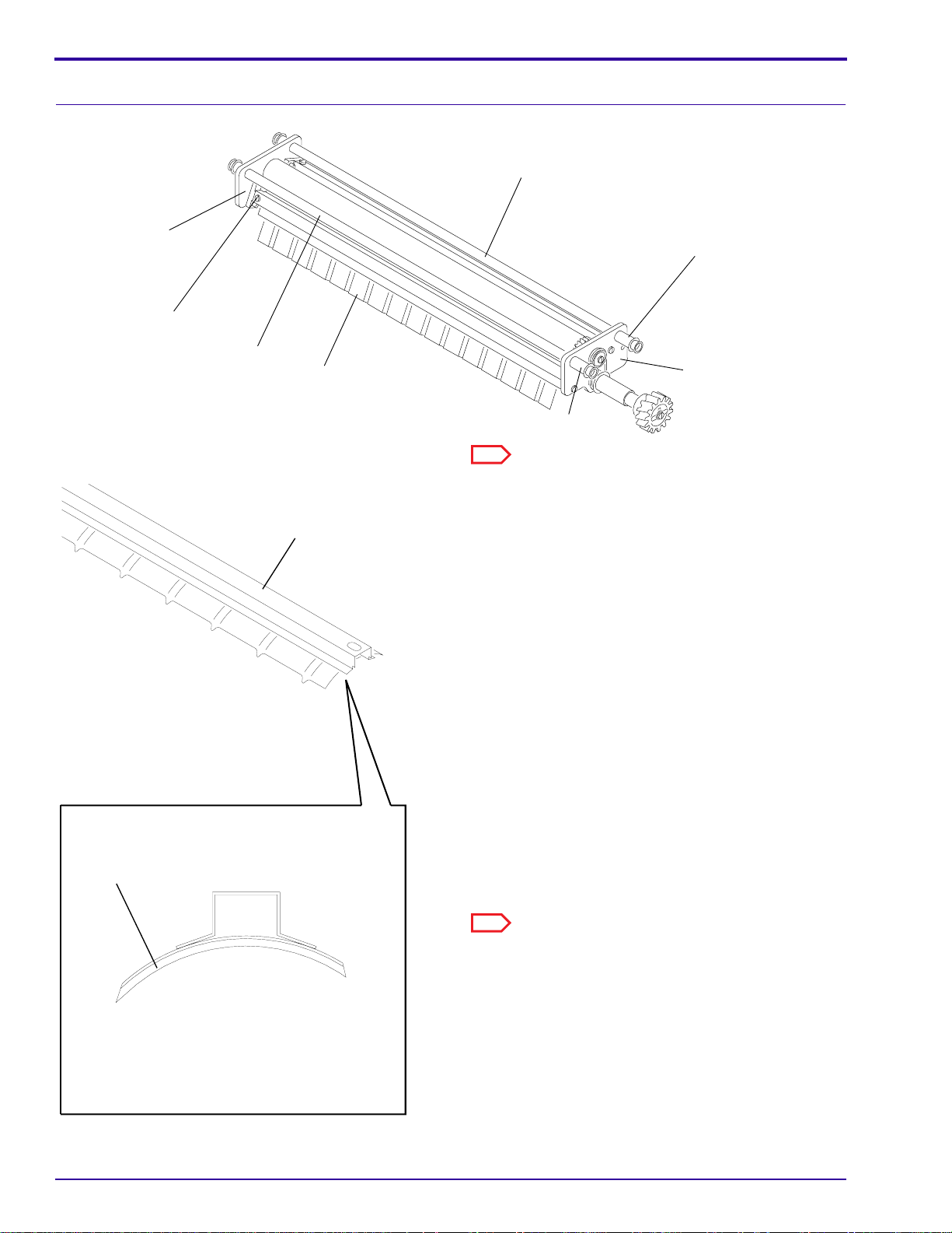
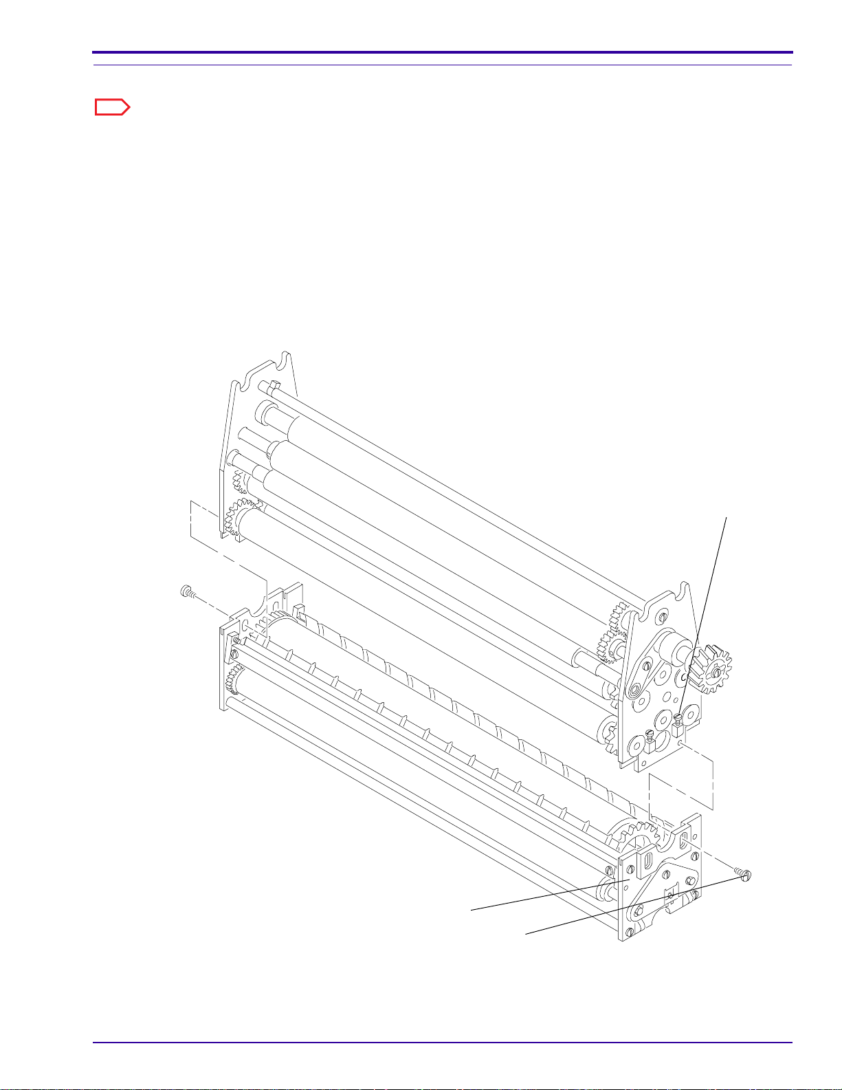
Replacement of a ROLLER in a TURNAROUND ASSEMBLY
Note
See the figure on Page 2–13 for this procedure.
[1] To remove an A ROLLER, remove:
• 2 SPRINGS
• LOCKING PLATE
• SCREW
• A ROLLER from the SHAFT
[2] To install a new A ROLLER, install:
• new A ROLLER on the SHAFT
• A ROLLER in the TURNAROUND
ASSEMBLY
• LOCKING PLATE
• 2 SPRINGS
[3] To remove the B ROLLER, remove:
• TURNAROUND ASSEMBLY from the RACK
• 2 SPRINGS
• LOCKING PLATE
• 2 A ROLLER ASSEMBLIES
• 2 SCREWS
• 2 BRACKETS
• EXIT GUIDE SHOE
• SHAFT, THRUST WASHERS, and the
BEARING from the B ROLLER
[4] Install the new B ROLLER and the other existing
parts.
[5] Check that the DRIVE CHAIN has the correct
tension. See Page 2–6 if adjustment of the
DRIVE CHAIN is necessary.
[6] Check that the long edges of the GUIDE SHOES
are in the directionof film travel. See the figureat
the left.
[7] Check that all GEARS in the TURNAROUND
ASSEMBLY engage.
long edge
GUIDE
SHOE
H112_0220CCA
H112_0220CA
2–12 September 1996 – 981901
Page 21
Disassembling a TURNAROUND ASSEMBLY
SHAFT
Adjustments and Replacements
B ROLLER
A ROLLER
EXIT
GUIDE
SHOE
A ROLLER
CHAIN
BRACKET (2)
HOLDING
SCREW (4)
SPRING
(2)
LOCKING
PLATE
SCREW (2)
H112_0075ECA
H112_0075EA
981901 – September 1996 2–13
Page 22
SERVICE MANUAL
R
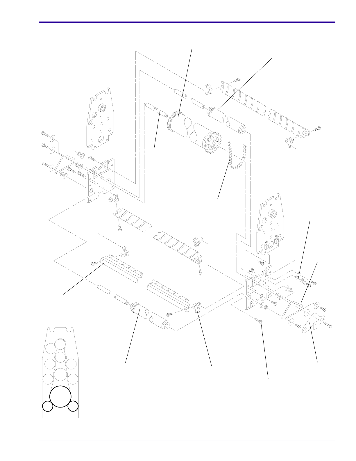
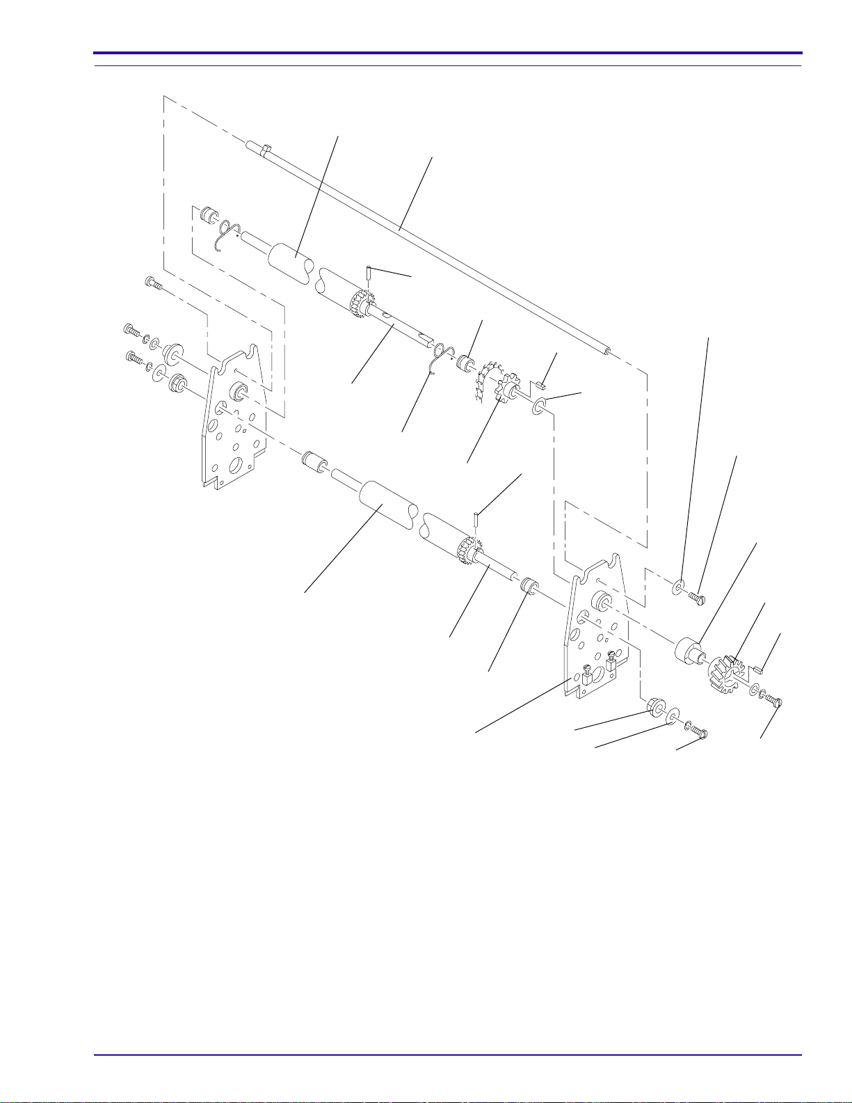
Replacement of the DRIVE ROLLER in the Developer RACK
SCREW
WASHER
LOCK
WASHER
SPRING
BEARING
SPACER
SPACER
SHAFT
DRIVE
ROLLER
SPROCKET
SPACER
KEY
THRUST
WASHER
DRIVE
GEAR
KEY
SCREW
non-drive
SIDE PLATE
drive
SIDE PLATE
SPRING
BEARING
SPACER
WASHER
H112_0106DCA
LOCK
WASHE
H112_0106DA
[1] Remove the 2 SPRINGS from the top of the RACK.
[2] Remove the SCREWS, WASHERS, LOCK WASHERS, GEAR, SPACERS, and BEARINGS from the DRIVE
ROLLER on the outside of both SIDE PLATES.
[3] Rotate the flat part of the SHAFT to the up position.
[4] Move the DRIVE ROLLER to the nondrive side and remove the KEY from the SPROCKET.
[5] Pull the SHAFT to the drive side to remove it from the nondrive SIDE PLATE.
[6] Remove the THRUST WASHER, SPROCKET, and SPACER.
[7] Continue to pull the SHAFT to the nondrive side.
[8] Remove the DRIVE ROLLER.
[9] Reverse the procedure to install the new DRIVE ROLLER.
2–14 September 1996 – 981901
Page 23
Adjustments and Replacements
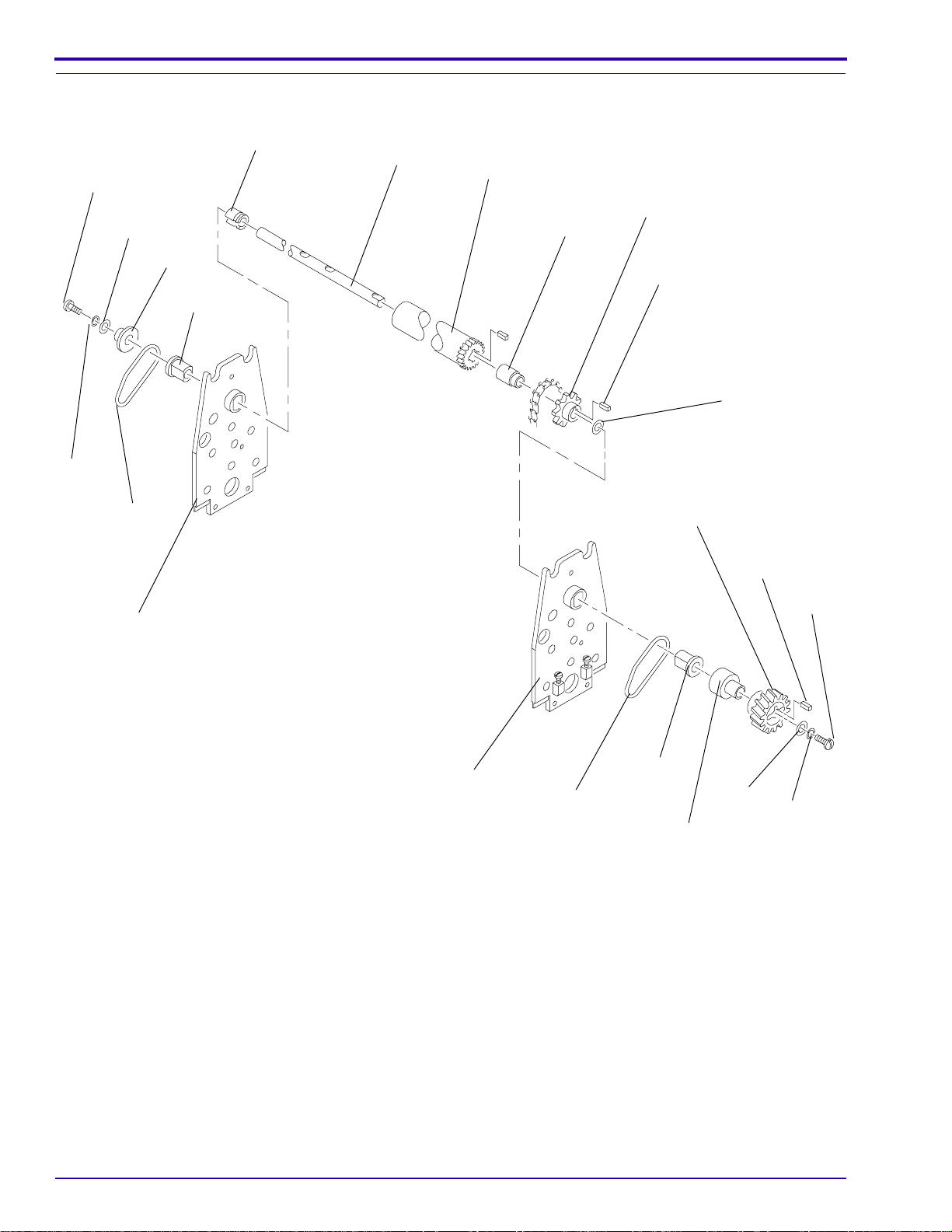
Replacement of the Resilient ROLLERS in the Fixer and Wash RACKS
DRIVE
ROLLER
TIE
ROD
PIN
SPACER
KEY
ID WASHER
SHAFT
THRUST
WASHER
SPRING
(2)
SPROCKET
PIN
SCREW (2)
SPACER
DRIVE
GEAR
DRIVEN
ROLLER
KEY
SHAFT
SPACER
H112_0105DCA
H112_0105DA
SIDE PLATE
BEARING
WASHER
SCREW
SCREW
[1] Remove:
• 2 SCREWS and the ID WASHER from the TIE ROD
• SCREWS, WASHERS, DRIVE GEAR, SPACERS, and BEARINGS from the DRIVE and DRIVEN
ROLLERS on the outside of both SIDE PLATES
[2] Rotate the flat part of the SHAFT of the DRIVE ROLLER to the up position.
[3] Move the DRIVE ROLLER to the nondrive side and remove the KEY from the SPROCKET.
[4] Remove the 2 SPRINGS.
[5] Pull the 2 SHAFTS of the DRIVE ROLLERand the DRIVENROLLER to the drive side to remove the SHAFTS
from the nondrive SIDE PLATE.
[6] Bend the SIDE PLATE slightly to allow removal of the DRIVE ROLLER.
[7] Remove the THRUST WASHER, SPROCKET, and SPACERS.
[8] Reverse the procedure to install new resilient ROLLERS.
981901 – September 1996 2–15
Page 24
SERVICE MANUAL
Adjustment of the DRYER RACK for Squareness
smooth, flat surface
H112_0104AA
[1] Remove the DRYER RACK from the
PROCESSOR and place it on a smooth, flat
surface.
[2] Loosen the 2 SCREWS and 2 NUTS from the
2 TIE RODS.
[3] Check that the SIDE PLATES touch the flat
surface evenly.
[4] Tighten the 2 SCREWS and 2 NUTS.
TIE ROD
TIE ROD
SCREW (2)
SIDE PLATE (2)
NUT (2)
H112_0064BCA
H112_0064BA
2–16 September 1996 – 981901
Page 25
Replacement of the DRIVE ROLLER in the DRYER RACK
O-RING
Adjustments and Replacements
PIN
COLLAR
PLENUM
AIR TUBE
O-RING
DRIVE
ROLLER
COVER
SHAFT
PIN
O-RING
COVER
[1] Remove:
• top and bottom COVERS from the DRYER RACK
• PLENUM
• first 3 AIR TUBES
• O-RING from the DRIVE GEAR
• PIN
• DRIVE GEAR
[2] On the nondrive side, remove:
• O-RING from the COLLAR
• PIN
• COLLAR
[3] On the drive side, remove the O-RING from the DRIVE ROLLER.
[4] Remove the PIN from the DRIVE ROLLER.
[5] Remove the SHAFT from the DRIVE ROLLER.
[6] Reverse the procedure to install the new DRIVE ROLLER.
PIN
DRIVE GEAR
H112_0103DCA
H112_0103DA
981901 – September 1996 2–17
Page 26
SERVICE MANUAL
Main Drive
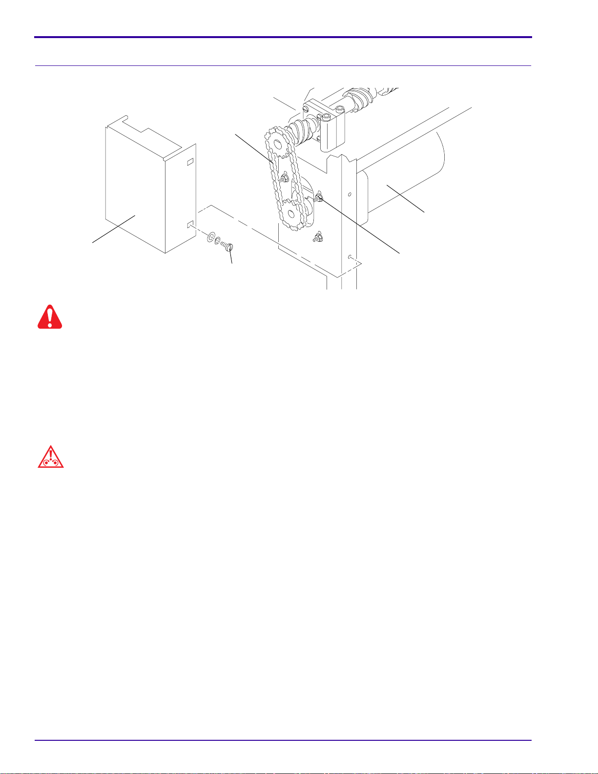
Adjustment of the Main DRIVE CHAIN
DRIVE
CHAIN
MAIN DRIVE MOTOR
CHAIN
GUARD
GUARD SCREW (2)
MOUNTING SCREWS (4)
H112_0181BCA
H112_0181BA
Warning
Moving parts.
[1] Disconnect the main power.
[2] Remove:
• drive SIDE PANEL
• 2 GUARD SCREWS
• CHAIN GUARD
[3] Loosen the 4 MOUNTING SCREWS.
Caution
Do not overtighten the DRIVE CHAIN.
[4] Move the MAIN DRIVE MOTOR up or down until the DRIVE CHAIN is tight. Do not overtighten the DRIVE
CHAIN.
[5] Tighten the 4 MOUNTING SCREWS.
[6] Install:
• CHAIN GUARD
• 2 GUARD SCREWS
• SIDE PANEL
2–18 September 1996 – 981901
Page 27
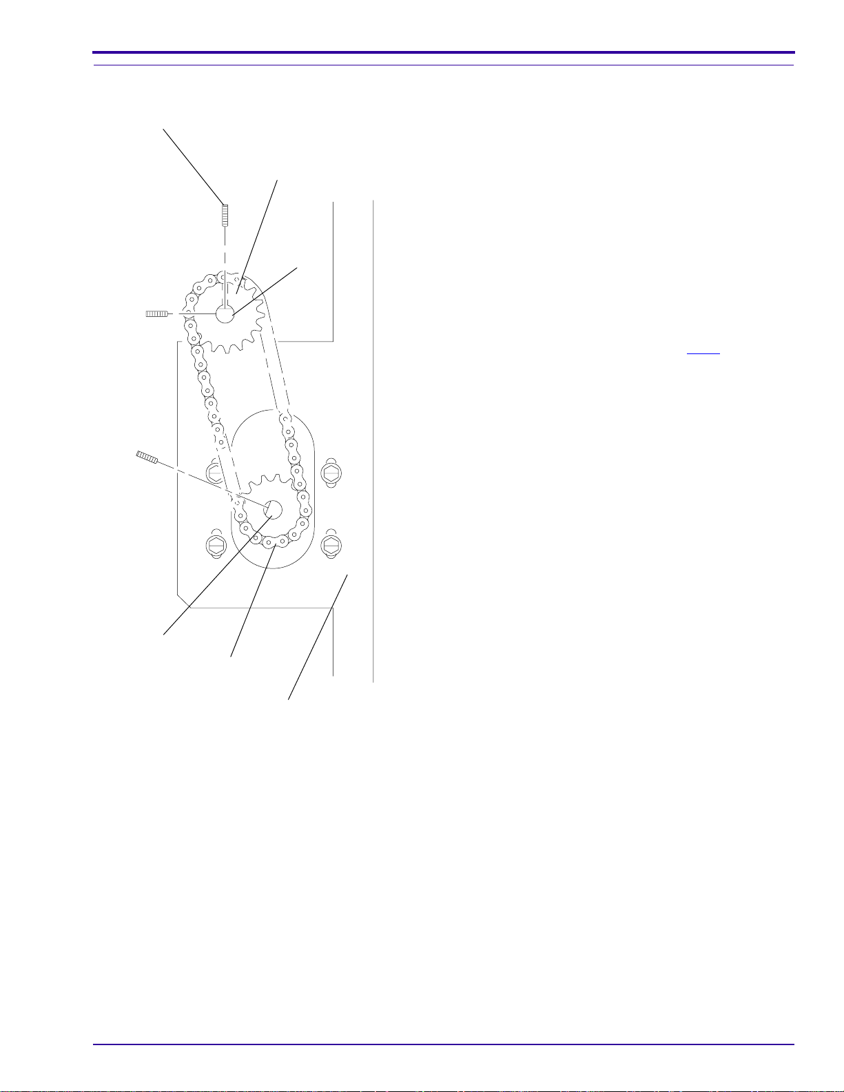
Alignment of the MAIN DRIVE MOTOR
SETSCREW (3)
SPROCKET (2)
DRIVE
SHAFT
Adjustments and Replacements
[1] Remove:
• drive SIDE PANEL
• 2 GUARD SCREWS
• CHAIN GUARD
[2] Loosen the 3 SETSCREWS.
[3] Align the SPROCKETS with the ends of the
DRIVE SHAFT and the MOTOR SHAFT.
[4] Tighten the 3 SETSCREWS.
[5] Check that the DRIVE CHAIN does not touch the
MOUNTING PLATE.
[6] Check that theSPROCKETontheDRIVE SHAFT
does not touch the DRIVE GEAR on the DRYER
RACK. See the figure on Page 2–17.
[7] Install:
• CHAIN GUARD
• 2 GUARD SCREWS
• SIDE PANEL
MOTOR
SHAFT
DRIVE
CHAIN
MOUNTING
PLATE
H112_0088CCA
H112_0088CC
981901 – September 1996 2–19
Page 28
SERVICE MANUAL
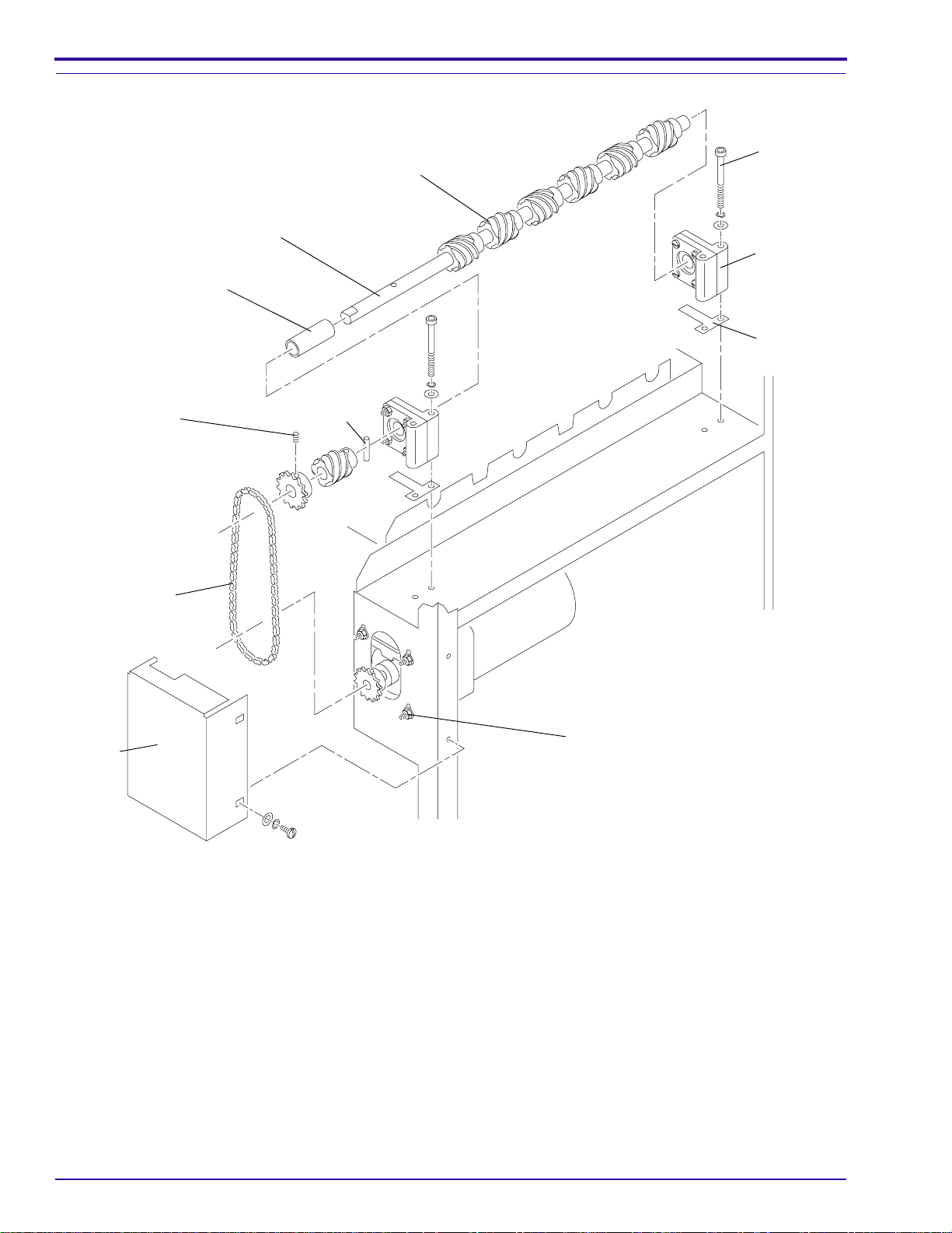
Replacement of the Main DRIVE SHAFT, WORM GEARS, or BEARING BLOCKS
SPACER
SETSCREW
DRIVE
SHAFT
PIN
WORM
GEAR
SCREW
(4)
BEARING
BLOCK
(2)
SHIM
(2)
DRIVE
CHAIN
MOUNTING SCREW (4)
CHAIN
GUARD
[1] Remove the CHAIN GUARD.
[2] Loosen the 4 MOUNTING SCREWS.
[3] Remove:
• DRIVE CHAIN
• 4 SCREWS from the 2 BEARING BLOCKS
• DRIVE SHAFT ASSEMBLY from the PROCESSOR
[4] If the PROCESSOR has SHIMS under the BEARING BLOCKS, save the SHIMS.
[5] Align the SHIMS with the holes for the SCREWS.
[6] Install:
• if necessary, new WORM GEARS or BEARING BLOCKS
• DRIVE SHAFT ASSEMBLY
H112_0182DCA
H112_0182DA
2–20 September 1996 – 981901
Page 29

Caution
Do not overtighten the 4 SCREWS.
[7] Install the 4 SCREWS in the BEARING BLOCKS.
[8] Adjust the position of the BEARING BLOCKS until the DRIVE SHAFT moves freely.
[9] Install the DRIVE CHAIN.
[10] Adjust the DRIVE CHAIN. See Page 2–6.
[11] Tighten the 4 MOUNTING SCREWS.
[12] Install the CHAIN GUARD.
Adjustments and Replacements
981901 – September 1996 2–21
Page 30
SERVICE MANUAL
Adjustment of the Speed of the MAIN DRIVE MOTOR
TOP COVER
ELECTRICAL
BOX
H112_0042ACB
H112_0042AC
[1] Determine the speed of the MAIN DRIVE MOTOR.
(a) Process sheets of 24 cm (10 in.) film in Extended and Standard Modes.
(b) Record the processing times. The correct time for a 24 cm (10 in.) film is:
Extended: 3 minutes and 23 seconds, ±2 sec
Standard: 2 minutes and 15 seconds, ±2 sec
SIDE
PANEL
ESD
Possible damage from electrostatic discharge.
[2] If the dry to dry processing times are not correct, adjust the speed of the MAIN DRIVE MOTOR.
(a) Remove the TOP COVER and the drive SIDE PANEL from the PROCESSOR.
(b) Open the ELECTRICAL BOX.
(c) Measure 24 cm (10 in.) on several new sheets of film.
(d) Set the STD/EXT SWITCH to “STD”.
(e) Feed half of the sheetsof film into the PROCESSOR. Measure the timefor each 24 cm (10 in.) of filmto
enter the PROCESSOR. The correct time is:
Standard: 20 seconds
(f) Set the STD/EXT SWITCH to “EXT”.
(g) Feed the other sheets of film into the PROCESSOR. Measure the time for each 24 cm (10 in.) of film to
enter the PROCESSOR. The correct time is:
Extended: 31 seconds
(h) If thetransport time is not correct, adjustR201 for the Extended Mode or R202 for theStandard Mode on
200 CIRCUIT BOARD. See the figure on the next page.
Important
It is important to check the speed of both modes, especially if an adjustment is necessary for one mode.
(i) Do Steps (a)-(h) again to check the processing times. Continue the procedure until theprocessingtimes
are correct.
(j) Close the ELECTRICAL BOX.
[3] Install the SIDE PANEL and the TOP COVER.
2–22 September 1996 – 981901
Page 31

Adjusting the Speed of the MAIN DRIVE MOTOR
R202
R201
Adjustments and Replacements
STD/EXT SWITCH
200 CIRCUIT BOARD
REPLENISHMENT
PUMP TIMER
ELECTRICAL
BOX
H112_0187ECE
H112_0187EC
981901 – September 1996 2–23
Page 32

SERVICE MANUAL
DRYER HEATER
Adjustment of the Temperature of the DRYER
DRYER
TEMPERATURE
CONTROL
KNOB
Insert
THERMOMETER
here
H112_0089ACC
H112_0089AC
[1] To check the temperature of the DRYER, insert a
THERMOMETER, Part No. 761217, under the
DRYER on the drive side of the PROCESSOR.
See the figure.
Important
The correct temperature for the DRYER depends on
the condition of the air and on the amount and type of
film fed into the PROCESSOR. Use the lowest
temperature possible for good drying.
[2] If necessary, adjust the temperature of the
DRYER,byrotating the DRYER TEMPERATURE
CONTROL KNOB:
clockwise
counterclockwise
increases the
temperature
decreases the
temperature
H112_0040AC
2–24 September 1996 – 981901
Page 33

Adjustments and Replacements
Replacement of the BLOWER ASSEMBLY
Warning
Dangerous voltage.
[1] Disconnect the main power.
[2] Remove:
• TOP COVER
• DRYER RACK
TOP COVER
Possible damage from electrostatic discharge.
H112_0028ACB
H112_0028AC
[3] Disconnect CONNECTORS 801 and 802, not shown, from the 800 CIRCUIT BOARD. See the figure on
Page 2–26 for the position of the 800 CIRCUIT BOARD.
[4] Disconnect the CABLE ASSEMBLY from the ELECTRICAL BOX.
[5] See the figure on Page 2–26. Remove:
• 2 MOUNTING SCREWS from the BRACKET
• 4 MOUNTING SCREWS from the DRYER HEATER
• BLOWER MOTOR and BRACKET
• BLOWER MOTOR from the BRACKET
[6] Install the new BLOWER MOTOR and the 4 MOUNTING SCREWS on the BRACKET.
• RECEIVING END COVER
• SIDE PANELS
ESD
Note
Do not tighten the 4 MOUNTING SCREWS on the BLOWER MOTOR until Step 9.
[7] Install the BRACKET on the DRYER HEATER.
[8] Install the 6 MOUNTING SCREWS.
[9] Tighten the MOUNTING SCREWS.
[10] Connect the CABLE ASSEMBLY to the ELECTRICAL BOX.
[11] Install:
• SIDE PANELS
• RECEIVING END COVER
• DRYER RACK
• TOP COVER
981901 – September 1996 2–25
Page 34

SERVICE MANUAL
Replacement of the BLOWER ASSEMBLY
MOUNTING
SCREW (4)
ELECTRICAL
BOX
RECEIVING
END
COVER
BLOWER
MOTOR
MOUNTING
SCREW (2)
800
CIRCUIT
BOARD
DRYER
HEATER
BRACKET
H112_0100DCA
H112_0100DA
2–26 September 1996 – 981901
Page 35

Adjustments and Replacements
Replacement of the DRYER HEATER or the HEATER CORE
Warning
Dangerous voltage.
[1] Disconnect the main power.
[2] Remove:
• TOP COVER
• DRYER RACK
TOP COVER
Possible damage from electrostatic discharge.
H112_0028ACB
H112_0028AC
[3] Disconnect CONNECTORS 801 and 802, not shown, from the 800 CIRCUIT BOARD. See the figure on
Page 2–28 for the position of the 800 CIRCUIT BOARD.
[4] Disconnect TB2-1, TB2-3, TB2-5, and the ground wire from the ELECTRICAL BOX.
[5] See the figure on Page 2–28. Remove:
• EXHAUST HOSE
• 4 SCREWS under the foam strips
• 6 MOUNTING SCREWS
• DRYER HEATER
[6] Do Steps 7 - 10 to install only a new HEATER CORE inside the DRYER HEATER. To install an entire new
DRYER HEATER, reverse the above procedure.
[7] Loosen the 2 SCREWS.
[8] Remove the HEATER TOP COVER.
[9] Remove the HEATER CORE from the DRYER HEATER:
(a) Remove the 4 HEX NUTS, not shown.
(b) Loosen the 4 MOUNTING SCREWS, not shown.
(c) Remove the HEATER CORE.
[10] Reverse the procedure to install the new HEATER CORE in the DRYER HEATER.
[11] Reverse Steps 2 - 5 to install the DRYER HEATER in the PROCESSOR.
• RECEIVING END COVER
• SIDE PANELS
ESD
981901 – September 1996 2–27
Page 36

SERVICE MANUAL
Replacement of the DRYER HEATER or the HEATER CORE
MOUNTING
SCREW (4)
ELECTRICAL
BOX
RECEIVING
END
COVER
800
CIRCUIT
BOARD
HEATER
TOP COVER
SCREW (2)
HEATER
CORE
MOUNTING
SCREW (2)
SCREW (2)
EXHAUST
HOSE
H112_0100DCB
H112_0100DA
2–28 September 1996 – 981901
Page 37

Adjustments and Replacements
Plumbing
Adjustment of the Developer Temperature
[1] Remove the TOP COVER.
[2] Insert a THERMOMETER of known accuracy, such as Part No. 761217, into the nondrive side of the
DEVELOPER TANK between the SIDE PLATE of the DEVELOPER RACK and the RACK SUPPORT.
Note
If checking both the Standard developer temperature and the Extended developer temperature, check for Standard
Mode first.
The correct temperatures are:
Standard: 33.3˚C ± 0.3˚C (92.0˚F 0.5˚F)
Extended: 35˚C ± 0.3˚C (95.0˚F 0.5˚F)
Insert THERMOMETER
here
H112_0121BCA
H112_0121BA
Caution
• Possible damage from electrostatic discharge. Use an ESD wrist strap.
• Use the POTENTIOMETER ADJUSTING TOOL TL-1481 to adjust R301 and R302.
[3] If a developer temperature adjustment is necessary, adjust R301 and R302 on the 300 CIRCUIT BOARD.
(a) Remove the drive SIDE PANEL from the PROCESSOR.
(b) Open the ELECTRICAL BOX.
(c) Use thePOTENTIOMETERADJUSTINGTOOLTL-1481toadjustthe developertemperaturebyrotating
R302 for Standard Mode or R301 for Extended Mode.
clockwise
counterclockwise
(d) Allow the developer to reach the new, adjusted temperature.
(e) Check the developer temperature in the DEVELOPER TANK with the THERMOMETER.
(f) If the developer temperature is not correct, do Steps (c) - (e) again.
(g) Close the ELECTRICAL BOX and install the SIDE PANEL.
[4] If the METER does not display the same temperature as the THERMOMETER, adjust the METER. See
Page 2–31.
increases the temperature
decreases the temperature
981901 – September 1996 2–29
Page 38

SERVICE MANUAL
Important
• After changing from Extended Mode to Standard Mode, set the DRYER TEMPERATURE CONTROL KNOB to
“0” and remove the TOP COVER for venting. Check that the METER displays the correct temperature before
adjusting R302 or processing film.
•Donot process films until the METER shows that the developer is at the correct temperature.
[5] Install the TOP COVER.
R302
R301
300 CIRCUIT
BOARD
100 CIRCUIT BOARD
H112_0041BCB
H112_0041BC
2–30 September 1996 – 981901
Page 39

Adjustment of the Developer Temperature METER
[1] Check:
TOP COVER
SIDE
PANEL
[2] Remove the TOP COVER.
[3] Check the temperature of the developer.
H112_0042ACB
H112_0042AC
ELECTRICAL
BOX
Adjustments and Replacements
• that the water to the PROCESSOR is on
• that the PROCESSOR is energized
• that the temperaturedisplayedonthe METER
has stablized
• for agitation of the developer in the
DEVELOPER TANK
• that the level of the developer is correct
(a) Insert a THERMOMETER of known
accuracy, such as Part No. 761217, into the
nondrive side of the DEVELOPER TANK
between the SIDE PLATE of the
DEVELOPER RACK and the RACK
SUPPORT. See the figure on Page 2–29.
(b) Compare the temperatures on the
THERMOMETER and on the METER.
Note
The correct temperature is:
METER
Standard: 33.3˚C ± 0.3˚C (92.0˚F ± 0.5˚F)
Extended: 35˚C ± 0.3˚C (95.0˚F ± 0.5˚F)
HOLES
H112_0184ACB
H112_0184AC
[4] If the temperatures are not the same, adjust the METER.
(a) Remove the drive SIDE PANEL from the PROCESSOR.
Caution
Possible damage from electrostatic discharge. Use an ESD wrist strap and a POTENTIOMETER ADJUSTING
TOOL TL-1481.
(b) Open the ELECTRICAL BOX.
(c) Check that CR10 on the 100 CIRCUIT BOARD is blinking.
(d) After CR10 hasblinked for 2 minutes,insert the POTENTIOMETER ADJUSTING TOOL TL-1481 through
the holes in the edge of the ELECTRICAL BOX. See the figure above.
(e) Rotate TL-1481 to adjust the POTENTIOMETER, not shown, on the METER.
clockwise
counterclockwise
increases the temperature
decreases the temperature display
(f) Check the developertemperaturewith the THERMOMETER. If the temperature is notthesameasonthe
METER, adjust the METER again.
981901 – September 1996 2–31
Page 40

SERVICE MANUAL
[5] Close the ELECTRICAL BOX.
[6] Check for correct operation of the PROCESSOR.
(a) Check that the DRYER and developer are at the correct temperatures.
(b) Feed 3 or 4 test sheets of film through the PROCESSOR.
[7] Install the drive SIDE PANEL and the TOP COVER.
2–32 September 1996 – 981901
Page 41

Removal of the Developer Temperature METER
METER
Adjustments and Replacements
[1] De-energize the PROCESSOR.
[2] Remove the TOP COVER and the drive SIDE
PANEL.
ESD
Possible damage from electrostatic discharge.
[3] Open the ELECTRICAL BOX.
[4] Remove from the METER:
• NUTS
• STAR WASHERS
• ground wire
• LOCK WASHER
• WASHER
• wire No. 27
• wire No. 13
• the red wire
• the black wire
• SHIELD
• 2 STANDOFFS
[5] Remove the CIRCUIT BOARD and the PLASTIC
COVER.
H112_0188CCA
H112_0188CC
MOUNTING STUD
PLASTIC COVER
CIRCUIT BOARD
SHIELD
STAR
WASHERS
NUT
WASHER
MOUNTING
STUD
2 STANDOFFS
981901 – September 1996 2–33
GROUND LUG
LOCK WASHER
NUT
ground wire
H112_0179BCA
H112_0179BA
Page 42

SERVICE MANUAL
Installation of the Developer Temperature METER
MOUNTING STUD
PLASTIC COVER
CIRCUIT BOARD
MOUNTING
STUD
2 STANDOFFS
ESD
Possible damage from electrostatic discharge.
GROUND LUG
SHIELD
WASHER
LOCK WASHER
NUT
STAR
WASHERS
ground wire
NUT
H112_0179BCA
H112_0179BA
[1] Align the holes of the PLASTIC COVER and the CIRCUIT BOARD.
[2] Install the PLASTIC COVER and the CIRCUIT BOARD on the MOUNTING STUDS inside the ELECTRICAL
BOX.
[3] Install the 2 STANDOFFS on the front and back MOUNTING STUDS.
Note
The center MOUNTING STUD is not used.
[4] Install the SHIELD on the 2 STANDOFFS.
[5] Install on each STANDOFF:
• WASHER
• LOCK WASHER
• NUT
[6] Connect:
• the red wire to the top TERMINAL
• the black wire to the second TERMINAL
• wire No. 27 to the third TERMINAL
• wire No. 13 to the bottom TERMINAL
[7] Install on the GROUND LUG:
• a STAR WASHER
• the ground wire
• another STAR WASHER
• a NUT
[8] Check that the METER operates correctly.
(a) Energize the PROCESSOR.
(b) Insert a THERMOMETER of known accuracy in the DEVELOPER TANK.
(c) Check that the temperature on the THERMOMETER and on the METER are the same.
2–34 September 1996 – 981901
Page 43

Adjustments and Replacements
H112_0184AC
HOLES
METER
H112_0184ACB
Note
The METER is operating correctly if the temperatures are the same. The correct developer temperature is:
Standard: 33.3˚C 0.3˚C (92.0˚F 0.5˚F)
Extended: 35˚C ± 0.3˚C (95.0°F ± 0.5°F)
(d) If the temperatures are the same, advance to Step 9 .
If the METER does not display the correct temperature, do Steps (e) to (g) below until the METER
displays the correct temperature.
ESD
Possible damage from electrostatic discharge.
(e) Insert the POTENTIOMETER ADJUSTING TOOL TL-1481 through the holes in the edge of the
ELECTRICAL BOX and rotate the POTENTIOMETER, not shown, on the CIRCUIT BOARD.
clockwise
counterclockwise
increase the temperature
decrease the temperature
Important
If decreasing the developer temperature, wait a few minutes before checking the developer temperature.
(f) Check that the developer temperature on the THERMOMETER in the DEVELOPER TANK and on the
METER are the same. If necessary, adjust the POTENTIOMETER again.
(g) Feed 3 sheets of test film to check the operation of the PROCESSOR.
[9] Close the ELECTRICAL BOX
[10] Install the SIDE PANEL and the TOP COVER.
981901 – September 1996 2–35
Page 44

SERVICE MANUAL
Replacement of the DEVELOPER HEATER
H112_0170BCB
H112_0170BA
DEVELOPER
TANK
TUBE
DEVELOPER
HEATER
2 SCREWS
[1] Disconnect the main power.
[2] Drain the DEVELOPER TANK, or install CLAMPS on the 2 TUBES to the THERMOWELL.
[3] Disconnect the wires to the DEVELOPER HEATER at TB2-9 and TB2-10.
TUBE
Caution
When you remove the DEVELOPER HEATER from the THERMOWELL, a small amount of developer may spill.
Clean any spilled solution.
[4] Remove:
• 2 SCREWS
• THERMOWELL
• DEVELOPER HEATER from the THERMOWELL
Caution
• Use only SEALANT TL-3230. AnyotherSEALANTwillcausedamage to the plastic. See the instructionspacked
with the SEALANT.
• Overtightening the DEVELOPER HEATER may cause damage to the THERMOWELL.
[5] Apply SEALANT TL-3230 to the threads of the new DEVELOPER HEATER.
(a) Cut the tube of SEALANT on an angle.
(b) Apply a small amount of SEALANT to the threads.
(c) Use the end of the tube of SEALANT to press the SEALANT into the threads.
[6] Insert the new DEVELOPER HEATER into the THERMOWELL.
[7] Check that the DEVELOPER HEATER isinthecorrectpositionthroughtheHEATER LOCATOR. See the figure
below.
[8] Hand tighten the DEVELOPER HEATER plus1⁄2 turn.
[9] Install the THERMOWELL and 2 SCREWS.
[10] Connect the wires to TB2-9 and TB2-10.
2–36 September 1996 – 981901
Page 45

[11] Remove the CLAMPS from the 2 TUBES, or fill the DEVELOPER TANK.
Adjustments and Replacements
5 mm
(13/64 in.)
13.9 cm
(5.500 .060 in.)
THERMOWELL
HEATER
HEATER LOCATOR
Replacement of the DEVELOPER OVER-TEMPERATURE THERMOSTAT
DEVELOPER
DEVELOPER
THERMISTOR
5 mm
(13/64 in.)
DEVELOPER
OVER-TEMPERATURE
THERMOSTAT
60
HEATER
LOCATOR
H048_0153BCA
H048_0153BA
13.9 cm
(5.500 + .060 in.)
-
THERMOWELL
H048_0162BCA
H048_0162BA
[1] Disconnect the main power.
[2] Drain the DEVELOPER TANK, or install CLAMPS on the 2 TUBES to the THERMOWELL. See the figure on
Page 2–36.
[3] Disconnect the OVER-TEMPERATURE THERMOSTAT at TB4-15, TB4-16, TB4-8, and TB4-9.
Caution
When you remove the OVER-TEMPERATURE THERMOSTAT from the THERMOWELL, a small amount of
developer may spill. Clean any spilled solution.
[4] Remove the OVER-TEMPERATURE THERMOSTAT from the THERMOWELL.
981901 – September 1996 2–37
Page 46

SERVICE MANUAL
Caution
Use only SEALANT TL-3230. Any other SEALANT will cause damage to the plastic. See the instructions packed
with the SEALANT.
[5] Apply SEALANT TL-3230 to the threads of the new OVER-TEMPERATURE THERMOSTAT.
(a) Cut the tube of SEALANT on an angle.
(b) Apply a small amount of SEALANT to the threads.
(c) Use the end of the tube of SEALANT to press the SEALANT into the threads.
Caution
Do not install the new OVER-TEMPERATURE THERMOSTAT below the position shown in the figure.
[6] Install the new OVER-TEMPERATURE THERMOSTAT 5 mm (13/64 in.) from the THERMOWELL. See the
figure above.
[7] Connect TB4-15, TB4-16, TB4-8, and TB4-9 to the new OVER-TEMPERATURE THERMOSTAT.
[8] Remove the CLAMPS from the 2 TUBES, or fill the DEVELOPER TANK.
Replacement of the DEVELOPER THERMISTOR
DEVELOPER
THERMISTOR
[1] Disconnect the main power.
[2] Drain the DEVELOPER TANK, or install CLAMPS on the 2 TUBES to the THERMOWELL. See the figure on
Page 2–36.
[3] Disconnect the DEVELOPER THERMISTOR at TB4-13 and TB4-14.
4 mm
(5/32 in.)
THERMOWELL
H112_0180BCA
H112_0180BA
Caution
When you remove the DEVELOPER THERMISTOR from the THERMOWELL, a small amount of liquid may spill.
Clean any spilled solution.
[4] Remove the DEVELOPER THERMISTOR from the THERMOWELL.
2–38 September 1996 – 981901
Page 47

Adjustments and Replacements
Caution
Use only SEALANT TL-3230. Any other SEALANT will cause damage to the plastic. See the instructions packed
with the SEALANT.
[5] Apply SEALANT TL-3230 to the threads of the new DEVELOPER THERMISTOR.
(a) Cut the tube of SEALANT on an angle.
(b) Apply a small amount of SEALANT to the threads.
(c) Use the end of the tube of SEALANT to press the SEALANT into the threads.
Caution
Do not install the new DEVELOPER THERMISTOR lower than shown in the figure.
[6] Install the new DEVELOPER THERMISTOR 4 mm (5/32 in.) from the DEVELOPER THERMOWELL.
[7] Connect TB4-13 and TB4-14 to the new DEVELOPER THERMISTOR.
[8] Remove the CLAMPS from the 2 TUBES, or fill the DEVELOPER TANK.
981901 – September 1996 2–39
Page 48

SERVICE MANUAL
Replacement of the HEAT EXCHANGERS
RACK
SUPPORT
SCREW (2)
TANK
CLIP (2)
Warning
Dangerous voltage.
[1] Disconnect the main power.
[2] Disconnect the water supply.
[3] Drain the 3 TANKS.
[4] Remove:
• 2 SCREWS from the RACK SUPPORT
• RACK SUPPORT
• TANK SEALS
• TANK CLIPS
[5] Disconnect all tubing from the TANK.
[6] If necessary, remove the 2 FITTINGS and the
WATER INLET TUBE. See the figure on
Page 2–42.
[7] Lift the nondrive side of the TANK, and then
remove the TANK from the PROCESSOR.
TANK
SEALS
(2)
H112_0146CCA
H112_0146CA
2–40 September 1996 – 981901
Page 49

GASKET (2)
FITTING (2)
O-RING (2)
WATER INLET
TUBE
TANK
HEATER
EXCHANGER
WASHER (2)
GLAND NUT (2)
Adjustments and Replacements
[8] Remove:
• 2 GLAND NUTS
• 2 O-RINGS
• 2 WASHERS
• HEAT EXCHANGER from the TANK
[9] Install:
• new HEAT EXCHANGER
• 2 O-RINGS
• 2 WASHERS
• 2 GLAND NUTS
• TANK in the PROCESSOR
• 2 FITTINGS, withnewGASKETSif in thefixer
TANK
• WATER INLET TUBE, wash TANK only
• TANK SEALS
• TANK CLIPS
• tubing
• RACK SUPPORT
[10] Pull the RACK SUPPORT toward the nondrive
side of the PROCESSOR and install the
2 SCREWS.
[11] Connect the water and fillthe3 TANKS with water.
[12] Check for leakage.
[13] Drain the water from the developer and fixer
TANKS. Fill the 2 TANKS with developer and fixer.
[14] Connect the main power.
H112_0098CCA
H112_0098CA
981901 – September 1996 2–41
Page 50

SERVICE MANUAL
Replacement of the RECIRCULATION PUMP
RECIRCULATION PUMP
Warning
Dangerous voltage.
[1] Disconnect the main power.
[2] Disconnect the water supply.
[3] Remove the TOP COVER and 2 SIDE PANELS.
[4] Drain the 3 TANKS.
[5] Use PINCH CLAMPS on the tubing to prevent leakage.
[6] Disconnect the tubing to the RECIRCULATION PUMP.
[7] Remove the MOUNTING SCREWS.
[8] Remove the RECIRCULATION PUMP.
[9] Reverse the above procedure to install a new RECIRCULATION PUMP.
[10] Connect the water supply.
[11] Remove the PINCH CLAMPS.
[12] Fill the 3 TANKS with water.
[13] Connect the main power.
MOUNTING
SCREW
H112_0166BCC
H112_0166BA
Caution
Never operate the RECIRCULATION PUMPS if the TANKS are empty.
[14] Actuate the RECIRCULATION PUMPS.
[15] Check for agitation on the surface of the solutions.
[16] Check for leakage.
[17] Drain the water thoroughly from the developer and fixer TANKS and fill the TANKS with developer and fixer.
2–42 September 1996 – 981901
Page 51

Replacement of the O-RING
Adjustments and Replacements
O-RING
WING
NUT
(4)
OUTER
PUMP
HOUSING
SCREW
WASHER
IMPELLER
SHAFT
H112_0084DCA
H112_0084DA
Warning
Dangerous voltage.
[1] Disconnect the main power.
[2] Remove the TOP COVER and the 2 SIDE PANELS.
[3] Install PINCH CLAMPS on the tubing of the RECIRCULATION PUMP to prevent leakage.
[4] Remove:
• 4 WING NUTS
• OUTER PUMP HOUSING
• O-RING
[5] Check that the O-RING is correctly seated.
[6] Install the OUTER PUMP HOUSING and the 4 WING NUTS.
[7] Remove the PINCH CLAMPS.
981901 – September 1996 2–43
Page 52

SERVICE MANUAL
[8] Connect the main power.
Caution
Never operate the RECIRCULATION PUMPS if the TANKS are empty.
[9] Actuate the RECIRCULATION PUMPS.
[10] Check for agitation on the surface of the solutions.
[11] Check for leakage.
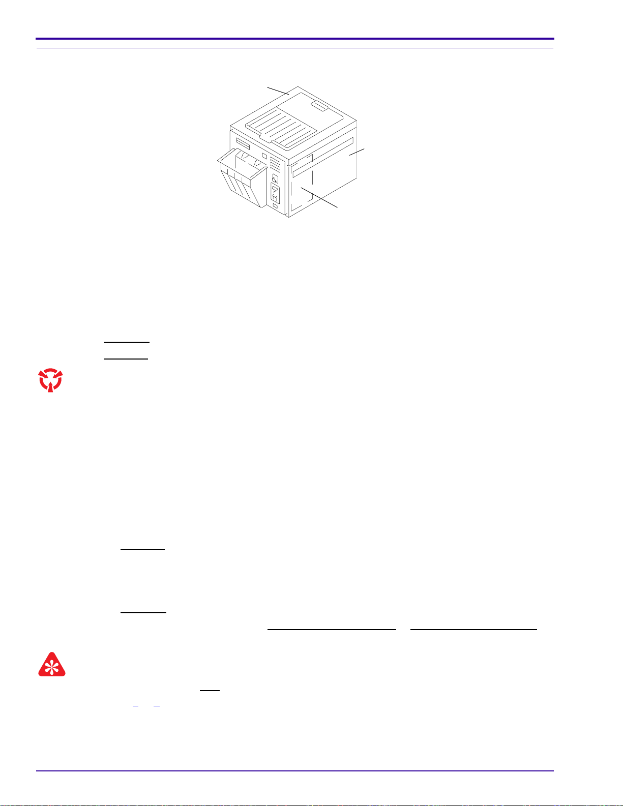
Replacement of a REPLENISHMENT PUMP
EXIT PANEL
TOP COVER
SIDE
PANEL
(2)
Warning
Dangerous voltage.
[1] Disconnect the main power.
[2] Disconnect the water supply.
PUMP
COVER
[3] Remove:
• TOP COVER
• 2 SIDE PANELS
• RECEIVING BIN
• DRYER TEMPERATURE CONTROL KNOB
• PUMP COVER
DRYER
TEMPERATURE
CONTROL KNOB
H112_0005ACC
H112_0005AC
• EXIT PANEL
[4] Disconnect the 2 MOTOR LEADS TB3-6 and
TB3-2 and the ground wire.
[5] Install a CLAMP on the REPLENISHER TUBE.
[6] Remove the REPLENISHER TUBE LINES from the REPLENISHMENT PUMP.
[7] Remove and keep the 2 SCREWS, the 2 WASHERS, and the 2 LOCK WASHERS.
[8] Remove the REPLENISHMENT PUMP.
[9] Reverse the above procedure to install a new REPLENISHMENT PUMP.
REPLENISHER
TUBE LINES
REPLENISHMENT
PUMP (2)
WASHER (2)
LOCK
WASHER (2)
H112_0097BCA
SCREW (2)
2–44 September 1996 – 981901
H112_0097BA
Page 53

Adjustment of the REPLENISHMENT PUMPS
Adjustments and Replacements
BRACKET
HOLE
BIN.
[2] Loosen the 2 SCREWS and remove the PUMP
COVER.
[3] Actuate the DETECTOR SWITCH, by lifting the
top DETECTOR ROLLER of the DETECTOR
CROSSOVER ASSEMBLY, until the
ADJUSTMENT SCREW is visible through the
hole in the BRACKET.
[4] Loosen the SETSCREW.
Caution
[1] Remove the TOP COVER and the RECEIVING
PUMP
COVER
SCREW (2)
H112_0005ACB
H112_0005AC
[7] See Page 2–46 and check theflow rates. If necessary, do Steps 2 - 6 again. See the table on Page 2–46 for
various replenishment rates.
[8] Install the TOP COVER, the PUMP COVER, and the RECEIVING BIN.
[9] Check that theREPLENISHMENTPUMPS operate correctly by feeding a sheet offilm into the PROCESSOR.
See Page 2–2.
Do not adjust the LOCKNUT on the other end of the
ADJUSTMENT SCREW.
[5] Rotate the ADJUSTMENT SCREW:
clockwise
counterclockwise
increases the flow rate
decreases the flowrate
[6] Tighten the SETSCREW.
SETSCREW
Do not
adjust!
LOCKNUT
H112_0030BCB
H112_0030BC
ADJUSTMENT
SCREW
REPLENISHMENT PUMP
BRACKET
HOLE
ADJUSTMENT SCREW
DECREASE INCREASE
OUTPUT
981901 – September 1996 2–45
Page 54

SERVICE MANUAL
Adjustment of the Replenishment Flow Rates
[1] Remove the TOP COVER.
[2] Lift the top DETECTOR ROLLER of the
DETECTOR CROSSOVER ASSEMBLY.
[3] Check that the replenisher solutions flow freely
through the TUBING along the drive side of the
PROCESSOR.
METAL
LATCH
DEVELOPER TUBING
QUICK
DISCONNECT
GRADUATED
CYLINDER
FIXER TUBING
[4] Press the METAL LATCH on the red QUICK
DISCONNECT to disconnect the DEVELOPER
TUBING.
[5] Pull the DEVELOPER TUBING slightly byrotating
the DEVELOPER TUBING over the edge of the
PROCESSOR.
[6] Insert the DEVELOPER TUBING into a
GRADUATED CYLINDER.
H112_0114ACA
H112_0114AC
[7] Lift the top DETECTOR ROLLER of the
DETECTOR CROSSOVER ASSEMBLY for the
correct time. See the table on the next page.
Note
The REPLENISHMENT PUMP will operate 3 seconds after you release the DETECTOR ROLLER.
[8] Check that the amount of developer in the GRADUATED CYLINDER is the same as in the table.
[9] If necessary, adjust the REPLENISHMENT PUMP. See Page 2–45 for the adjustment procedure.
[10] If necessary, so Steps 7 - 9 again.
[11] Connect the QUICK DISCONNECT.
[12] Do this procedure again to check the flow rate of the fixer.
Film Size
Processed
Only 35 x 35 cm
(14 x 14 in.) film
Average size
film intermix
Only 35 x 43 cm
(14 x 17 in.) film
Use
Condition
High
Medium
Low
High
Medium
Low
High
Medium
Low
Average Amount
of Film
per 8 Hours of
Processor Operation
90 sheets or more
31 - 89 sheets
30 sheets or less
115 sheets or more
41 - 114 sheets
40 sheets or less
75 sheets or more
26 - 74 sheets
25 sheets or less
Replenishment Flow Rate
mL per 35 cm (14 in.)
28 sec
of Film Travel
Developer Fixer
50 70
65 85
80 100
50 70
65 85
80 100
— —
mL per 43 cm (17 in.)
34 sec
of Film Travel
Developer Fixer
— —
— —
60 85
80 100
100 120
2–46 September 1996 – 981901
Page 55

Film Size
Processed
Only 18 x 24 cm
Kodak Min-R
E Film
Only 18 x 24 cm
Kodak Min-R
M Film
Only 18 x 24 cm
Kodak Min-R
H Film
Only 18 x 24 cm
Kodak Min-R
2000 Film
Use
Condition
High
Medium
Low
High
Medium
Low
High
Medium
Low
High
Medium
Low
Average Amount
of Film
per 8 Hours of
Processor Operation
150 sheets or more
60 - 149 sheets
59 sheets or less
150 sheets or more
60 - 149 sheets
59 sheets or less
150 sheets or more
60 - 149 sheets
59 sheets or less
150 sheets or more
60 - 149 sheets
59 sheets or less
Replenishment Flow Rate
mL per 24 cm
26 sec
of Film Travel
in Standard Mode
Developer Fixer
— —
30 30
30 35
35 40
50 30
50 35
50 40
20 30
20 35
20 40
Adjustments and Replacements
mL per 24 cm
36 sec
of Film Travel
in Extended Mode
Developer Fixer
20 30
27 35
35 40
— —
— —
— —
Note
• Kodak
• Replenishment rates are based on one sheet of 18 x 24 cmfilm. Iffeedingtwosheets,doublethereplenishment
• For best results, feed film consistently.
• Slight sensitometric changes will occur as subsequent films are processed through a freshly started process.
• For 30 sheets of film or less per day, flooded replenishment is recommended.
• Film travel time includes feed time plus an approximate 3-second delay.
RP
X-Omat
Chemicals are recommended.
rates.
This is known as “seasoning” and is normal with any photographic process. Process control targets may have
to be adjusted slightly to compensate.
981901 – September 1996 2–47
Page 56

SERVICE MANUAL
2–48 September 1996 – 981901
Page 57

Periodic Maintenance
Section 3: Periodic Maintenance
General Information
Note
• This section includes additional procedures that are not in the Operator Manual, Publication No. 981799.
• To provide for optimum operation of the PROCESSOR, it is important to use the following procedures.
[1] Process 5 sheets of unprocessed film before you begin the periodic maintenance. Check for artifacts.
[2] Check for:
• cleanliness
• broken parts
• wear of parts
• leakage
• site specifications
[3] Install new parts for the broken parts and parts that have wear.
Warning
Dangerous Voltage
• Disconnect the main power before lubricating the parts.
• Do not allow anyoil or grease to touchthe CROSSOVERS and RACK ASSEMBLIES or to drip into the TANKS.
[4] If necessary, provide lubrication.
[5] Use the correct procedure to clean parts.
[6] Make the necessary adjustments.
[7] Process 5 sheets of unprocessed film in the PROCESSOR after you have performed any service. Check for
artifacts.
Periodic Maintenance Schedule
See Service
ITEM TO CHECK WEEKLY MONTHLY
Feed Shelf Alignment X 2–1
Detector and Crossover Assemblies X 3–3 and 3–4
Rollers
Gears
Guide Shoes
Bearings
Brackets
Nuts
Rack Assemblies X 3–5
Rollers
Gears
Guide Shoes
Procedure on Page:
981901 – September 1996 3–1
Page 58

SERVICE MANUAL
ITEM TO CHECK WEEKLY MONTHLY
Procedure on Page:
Bearings
Chain
Springs
Rewet Rollers
Turnaround Assemblies X 3–6
Rollers
Springs
Main Drive Assembly X 3–7
Plumbing X 3–11
Connections
Tubing
Recirculation System X 3–11
Developer Filter Or after 1000 films 3–12
Developer Temperature X 3–12
Water Flow to the Processor X
Chemical Replenishment X 3–12
Strainer Assemblies X 3–12
Dryer Sections 3–8
Bearings X
Air Tubes X
Rollers X
O-Rings X
Dryer Temperature X
Processor Speeds X
EXT
STD
See Service
Lubrication Table
Part Lubricant Frequency Procedure
Main DRIVE CHAIN NLGI - No. 2 Lithium Ball
andRollerBearingGrease,
As necessary.
Check each month.
Apply to surface of Chain.
TL-2324
RECIRCULATION PUMPS Light oil, such as SAE
No. 20 Motor Oil, TL-2244
Every 6 months. Several drops in the oil
holes.
Main DRIVE MOTOR No lubrication necessary ---- ---GEAR HOUSING of the
No lubrication necessary ---- ----
Main Drive Motor
BEARINGS in the Dryer
Blower Motor
3–2 September 1996 – 981901
Light oil, such as SAE
No. 20 Motor Oil, TL-2244
Every 6 months. Several drops in the oil
holes.
Page 59

Roller Transport
DETECTOR SWITCHES and DETECTOR CROSSOVER ASSEMBLY
DETECTOR
ROLLER
ROCKER
ARM
DETECTOR
SWITCH (2)
SCREW
Periodic Maintenance
1.6 mm
(0.06 in.)
MAGNET (2)
ROCKER ARM
DETECTOR
SWITCH (2)
H112_0112BCA
H112_0112BA
[1] Check that theDETECTOR SWITCHES operatetheREPLENISHMENT PUMP. SeePage 2–2foradjustment.
[2] Clean the DETECTOR ROLLERS with a damp, lint-free cloth or natural sponge.
[3] Check:
• That the ROCKER ARM moves freely. If not, remove the ROCKER ARM and BUSHING and clean with
warm water.
• For corrosion of the ROCKER ARM. If necessary, install a new ROCKER ARM.
• For squareness of the DETECTOR CROSSOVER ASSEMBLY. See Page 2–4.
• That the DETECTOR CROSSOVER ASSEMBLY is seated correctly.
981901 – September 1996 3–3
Page 60

SERVICE MANUAL
CROSSOVER ASSEMBLIES
BRACKET
ROLLER
ROLLER
GEAR
NUT
DRIVE
GEAR
GUIDE
SHOE
BEARING
H112_0056BCB
H112_0056BA
[1] Remove the CROSSOVER ASSEMBLIES from the PROCESSOR.
[2] Rinse the CROSSOVER ASSEMBLIES with running water.
[3] If necessary, use a soft brush and warm water or:
Developer/Fixer Crossover Assembly Kodak Liquid Developer System Cleaner
Fixer/Wash Crossover Assembly Kodak Fixer/Wash System Cleaner
[4] Check the ROLLER GEARS for broken or worn teeth. If necessary, install new ROLLERS.
[5] Check that the RESILIENT ROLLER is smooth. If necessary, install a new RESILIENT ROLLER.
[6] Check the BEARING, BRACKETS, and NUTS for wear or broken parts. If necessary, install new parts.
[7] Check the DRIVE GEAR for wear or burrs. If necessary, install a new DRIVE GEAR.
[8] Place the CROSSOVER ASSEMBLIES on a flat surface with the GUIDE SHOES up.
[9] Check for squareness. See Page 2–5 of this manual.
3–4 September 1996 – 981901
Page 61

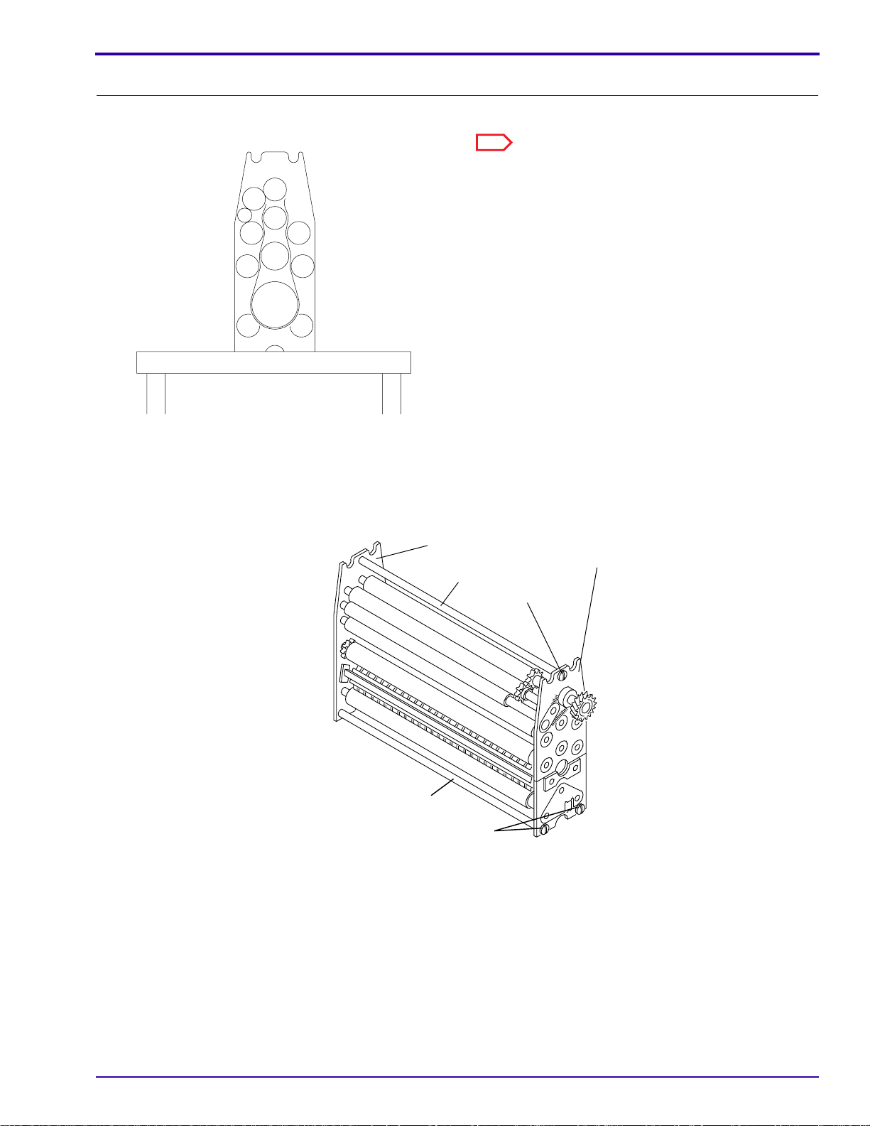
RACK ASSEMBLIES and ROLLERS
DRIP TRAY
SPLASH GUARD
H112_0015ACA
H112_0015AC
Periodic Maintenance
Caution
When you remove the FIXER RACK ASSEMBLY,
install a SPLASH GUARD between the DEVELOPER
TANK and the FIXER TANK to prevent contamination
of the developer. Usea DRIP TRAY when youremove
the RACK ASSEMBLIES. Install the RACK
ASSEMBLIES slowly into the TANKS.
[1] Remove the RACK ASSEMBLIES from the
PROCESSOR.
[2] Rinse the RACK ASSEMBLIES with warm water,
approximately 44°C (110°F).
Note
Discoloration of the ROLLERS is normal.
[3] If necessary, use a soft brush or:
Assembly Use:
Developer Rack
Assembly
Fixer Rack Assembly
or Wash Rack
Assembly
Kodak Liquid
Developer System
Cleaner
Kodak Fixer/Wash
System Cleaner
smooth, flat surface
H112_0110AA
[4] Remove the STUDS from the drive side.
[5] Remove all the OUTER ROLLERS on the entrance side except the bottom OUTER ROLLER.
[6] Clean the INNER and OUTER ROLLERS.
[7] Check all SPROCKETS and GEARS for wear.
[8] Check that all ROLLERS are straight.
[9] Install the ROLLERS in the RACK ASSEMBLY.
[10] Check:
• That the ROLLERS are installed correctly.
• The REWET ROLLER for wear.
• That the REWET ROLLER is smooth.
• That the REWET ROLLER touches the ROLLERS above and below it.
• The RACK ASSEMBLY for squareness. See Page 2–4.
981901 – September 1996 3–5
Page 62

SERVICE MANUAL
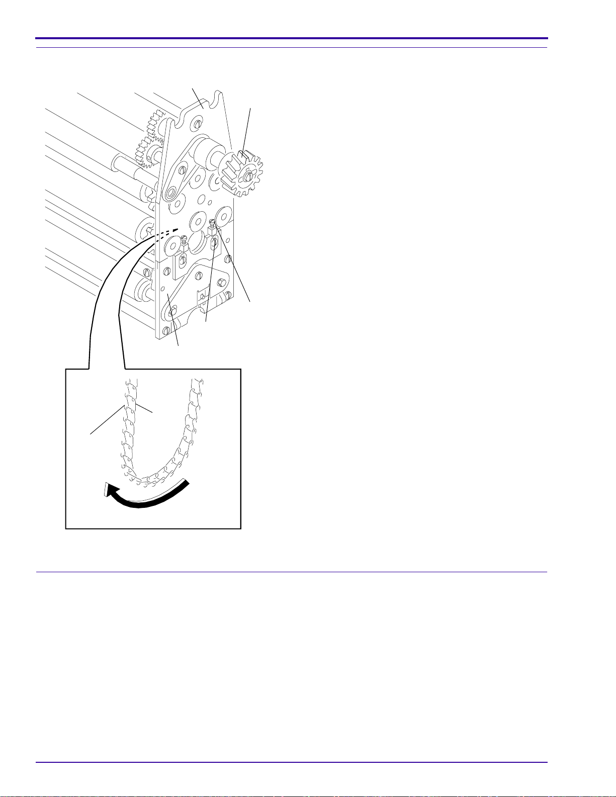
TURNAROUND ASSEMBLIES
bottom view
BEARING
SHAFT
SPRING
ROLLER
top view
LOCKING
PLATE
BEARING
[1] Remove the TURNAROUND ASSEMBLIES from the RACK ASSEMBLIES.
[2] Clean the DEVELOPER TURNAROUND ASSEMBLY with
[3] Clean the FIXER TURNAROUND ASSEMBLY with
Kodak
Kodak
Liquid Developer System Cleaner.
Liquid Fixer/Wash System Cleaner.
[4] Check the tension of the SPRINGS. If necessary, install new SPRINGS.
[5] Check the BEARINGS. If a ROLLER does not rotate freely on the SHAFT, install new BEARINGS.
[6] Check that the ROLLERS move freely in the slots of the LOCATING PLATES.
[7] Check that the surfaces of the ROLLERS are smooth.
[8] Wipe all ROLLERS with a damp cloth or sponge.
H112_0108DCA
H112_0108DA
3–6 September 1996 – 981901
Page 63

DRIVE CHAIN and SPRINGS
Periodic Maintenance
SPROCKET
GEAR
TURNAROUND
ASSEMBLY
SHAFT
DRIVE
GEAR
SPRING
BEARING
LOCKING
PLATE
[1] Manually rotate the DRIVE GEAR to check the
LINKS of the DRIVE CHAIN.
[2] Check the tension of the DRIVE CHAIN.
Important
If the DRIVE CHAIN is too tight,theROLLERSwill bind
and cause wear to the BEARINGS. If the DRIVE
CHAIN is too loose, the ROLLERS will not move
smoothly.
[3] If necessary, adjust the DRIVE CHAIN. See
Page 2–6.
Note
If you adjust the DRIVE CHAIN, adjust both sides of the
TURNAROUND ASSEMBLY by the same distance.
[4] Check theSPRINGSfor wear. Ifnecessary,install
new SPRINGS.
LINK
DRIVE CHAIN
H112_0109CCB
H112_0109CA
981901 – September 1996 3–7
Page 64

SERVICE MANUAL
DRYER
DRYER TEMPERATURE
CONTROL KNOB
Insert THERMOMETER
here
H112_0043ACC
H112_0043AC
[1] Check that all ROLLERS rotate freely.
[2] Check for broken GEARS. If necessary, install
new ROLLERS.
[3] Remove dirt and dust from the AIR TUBES.
[4] Check the SPRINGS, not shown, for wear. If
necessary, install new SPRINGS.
[5] Check the temperature at the bottom of the
DRYER on the drive side of the PROCESSOR.
[6] If necessary, turn the DRYER TEMPERATURE
CONTROLKNOB to adjust the temperature. See
Page 2–24.
Note
The temperature of the DRYER should be as low as
possible for drying the film.
GEAR
SPRING
ROLLER
AIR TUBE
H112_0095BCA
H112_0095BA
3–8 September 1996 – 981901
Page 65

Main Drive
DRIVE
CHAIN
Periodic Maintenance
WORM
GEAR
BEARING
SPROCKET
H112_0183BCA
[1] Check the DRIVE CHAIN for wear. If necessary, install a new DRIVE CHAIN. See Page 2–6.
[2] Check the tension of the DRIVE CHAIN. See Page 2–6 if adjustment is necessary.
[3] If necessary, lubricate the DRIVE CHAIN.
[4] Check the BEARINGS, SPROCKETS, and WORM GEARS for wear. If necessary, install new parts.
[5] Check the teeth of the SPROCKETS. If the teeth are sharp, install new SPROCKETS.
[6] Check the WORM GEARS for burrs. If necessary, install new WORM GEARS.
[7] Rinse the WORM GEARS with a small amount of warm water.
H112_0183BA
981901 – September 1996 3–9
Page 66

SERVICE MANUAL
Plumbing
General
TANK (3)
WEIR (3)
FILL TUBE
H112_0154DCB
H112_0154DA
[1] Check all the CONNECTIONS to the RECIRCULATION PUMPS, the VALVES, TUBING, and TANKS for
leakage.
[2] Check that the temperature of the incoming water is 4 - 30°C (40 - 85°F).
[3] Check the flow rate of the wash water.
(a) Drain the TANKS.
(b) Remove:
• FIXER/WASH CROSSOVER ASSEMBLY
• DRYER RACK ASSEMBLY
• WASH RACK ASSEMBLY
(c) Turn on the water.
(d) Measure theflowrateof the water. It should be 946 mL/min (1⁄4gal/min), +10% -0%,fromthe water FILL
TUBE.
3–10 September 1996 – 981901
Page 67

RECIRCULATION PUMPS
Periodic Maintenance
DRIP TRAY
SPLASH GUARD
H112_0015ACA
H112_0015AC
Note
When doing periodic maintenance and when changing
the processing solutions, check the RECIRCULATION
PUMPS and tubing.
Caution
• Always use a DRIP TRAY and the SPLASH
GUARD when you remove RACK ASSEMBLIES.
• Never operate theRECIRCULATIONPUMPSif the
TANKS are empty.
[1] Actuate the RECIRCULATION PUMPS.
[2] Check for:
• agitation on the surface of the solutions
• leakage
• excessive noise in the RECIRCULATION
PUMPS
RECIRCULATION PUMP
H112_0166BCB
H112_0166BA
981901 – September 1996 3–11
Page 68

SERVICE MANUAL
DEVELOPER FILTER and Temperataure
CAP
O-RING
[1] Install a new DEVELOPER FILTER at least once
a month or after approximately 1000 sheets of
film.
[2] Check that the O-RING is correctly seated before
you install the CAP.
[3] Check the temperature of the developer. If
necessary, adjust R301 or R302. See Page 2–
29.
DEVELOPER
FILTER
FILTER
HOUSING
H112_0169CCA
H112_0169CA
Chemical Replenishment
[1] Check the replenishment flow rates by doing the procedure on Page 2–46.
[2] Check the STRAINERS for debris.
(a) Place CLAMPS on the tubing to stop the replenishment flow.
(b) Disassemble the STRAINER ASSEMBLIES.
(c) Use a brush and warm water to clean the STRAINER ASSEMBLIES and to remove dirt and chemical
deposits from the SCREENS.
3–12 September 1996 – 981901
Page 69

INTERLOCK SWITCH
Periodic Maintenance
STRAINER ASSEMBLY
SCREEN
H112_0092BCA
H112_0092BA
MAGNET
TOP COVER
MAGNET
INTERLOCK
SWITCH
H112_0091BCA
H112_0091BA
[1] Check the operation of the INTERLOCK SWITCH:
(a) Press one of the RUN/STANDBY SWITCHES.
(b) Remove the TOP COVER. TheMAINDRIVE MOTOR,the BLOWER MOTOR, andthe DRYERHEATER
will stop.
(c) If the DRYER HEATER does not stop, adjust the position of the MAGNETS on the TOP COVER.
(d) Install the TOP COVER and do Steps (a) - (c) again.
[2] If the MAIN DRIVE MOTOR, the BLOWER MOTOR, and the DRYER HEATER do not stop, install a new
INTERLOCK SWITCH.
981901 – September 1996 3–13
Page 70

SERVICE MANUAL
3–14 September 1996 – 981901
Page 71

Correcting Difficulties
Section 4: Correcting Difficulties
Important
• Many film transport and sensitometric difficulties can be caused or aggravated by inadequate hardening of the
emulsion due to underreplenishment of the developer and fixer solution.
• Another cause of inadequate hardening of the emulsion may be deterioration of the developer replenisher
because of age or storage at too high a temperature. Do not mix more than a 2-week supply of developer
replenisher.
1. Transport Failure
2. Surface Artifacts
3. Abnormal Film Densities
4. Wet Films
5. Low Solution Levels
6. Overlapping of Films
123456
• • Film Feeding Error
Feed only single thicknesses of film. Feed the next film only after
the film feed signal sounds. If there is no film feed signal, refer
the difficulty to qualified personnel.
• • • • Feed only compatible films.
• • Check that all Racks and Crossovers are seated correctly.
• • Check that the surfaces of all the Rollers are clean and smooth, especially in
the developer Turnaround Assembly.
• • Check that the Dryer Air Tubes are in the correct positions.
• • Remove any dirt from the Dryer Rollers and Air Tubes, especially the slots.
Use a bottle brush and rinse with water.
•••• Check the settings for correct replenishment. Check the replenishment
system: Tubing kinks, Pump operation, Detector Switches, and
Replenishment Pump.
• Adjust the Dryer temperature control setting to the lowest possible
temperature that still allows good drying.
• Clean the Feed Shelf and Detector Rollers.
• • • Clean any biological growth in the wash Tank with a mild solution of chlorine
bleach. Use 60 mL (2 fluidounces) of bleach per 3.8 L (1 gallon) of water.
Wipe the Tanks with a soft sponge.
• • Check that the Weirs are seated correctly.
Check that the Tanks are full.
•••• •Change any chemicals that were not mixed correctly, are exhausted, or are
contaminated.
Change the Developer Filter if necessary.
Check that replenishment flow rates are correctly set. If necessary, fill the
Replenishment Tanks.
Mix the developer replenishment in quantities not to exceed a
2-week supply.
Always use a Splash Guard and Rack Drip Tray when lifting the
fixer Rack to prevent contaminating the developer.
Mix chemicals as directed.
981901 – September 1996 4–1
Page 72

SERVICE MANUAL
1. Transport Failure
2. Surface Artifacts
3. Abnormal Film Densities
4. Wet Films
5. Low Solution Levels
6. Overlapping of Films
123456
• • • Check that all Rollers are in place and positioned and rotating correctly.
• • • Check that all Roller Gears, Sprockets, and Idlers are engaged.
• • • Replace any Rollers that have broken or worn Gudgeons.
• • • Replace any Bearings that do not allow the Turnaround Rollers to rotate
correctly.
• • Check the tension on the Rack Chain. Check that the Rollers do not hesitate
and that the Chain moves smoothly.
• With the Processor on, check for movement on the surface of the solutions.
Movement indicates recirculation. If you do not observe any movement,
check that the Tubing is not kinked, that the Recirculation Pump is operating,
and that the Developer Filter is clean and in position.
• • If the incoming wash water is dirty, clean the Rack and Tank thoroughly.
Change the incoming water Filter. Make sure to use the correct water Filter.
• Check that the Poppets in the Replenishment Pump are clean and are not
distorted or worn. If the Poppets are preventing proper replenishment, have
qualified personnel clean or replace them.
• Check that the Dryer air exhaust is free from any obstruction and is installed
correctly according to specifications in the Installation Instructions.
• • Check that theTurnaround Assemblies are adjustedcorrectly. Make surethat
the Turnaround Assemblies are square with the Racks.
• • Check the incoming water temperature. Temperature must be between 4˚C
(40˚F) and 30˚C (85˚F).
• Check that the Orifices in the developer and fixer recirculation lines are the
correct size and are not plugged.
• Check that the correct Bulb and Safelight Filter are in the Safelight and at the
correct distance from the Feed Shelf and work surface.
• • Check that the Top Cover and Panels are tight on the Processor.
Check that there are no leaks in the Lighttight Gasket.
• 10 x 10 cm films - feed films diagonally if they fail to transport reliably.
• Check the timedelay. For alltransport speeds, the Buzzer shouldsound once
the trailing edge of the film has advanced 75 mm (3 in.) into the Processor.
• • • • Check that the solution levels in the Tanks are at the overflow Weirs.
• • Adjust the Guide Shoes correctly.
NOTE: Most often in the developer Turnaround Assembly. Adjust the long
edges of the Guide Shoes in the exit Turnaround Assembly as close as
possible to the Rack Roller above them.
• Check for solution in the Replenishment Tanks. Fill if necessary.
NOTE: Mix developer replenisher in quantities not to exceed a 2-week
supply.
• Check that the correct Bulb is in the Safelight.
4–2 September 1996 – 981901
Page 73

Correcting Difficulties
1. Transport Failure
2. Surface Artifacts
3. Abnormal Film Densities
4. Wet Films
5. Low Solution Levels
6. Overlapping of Films
123456
• With a thermometer of known accuracy, check that the temperature of the
developer is correct for the mode selected -- Standard or Extended. If
necessary, have qualified personnel make adjustments.
NOTE: Check the incoming water temperature. It must be a minimum of 4˚C
(7˚F) lower than the desired developer temperature.
• If the digital temperature display is blank and all noise ceases, including the
Main Drive Motor and the ventilation Fan:
Turn off the main power and the main power switch on the Processor.
Remove the drive Side Panel.
Open the Electrical Box Cover.
Check the Fuse. If necessary, install a new Fuse, making certain to
match the size and type of the existing one.
• • Check that the film is compatible with the selected mode, Standard or
Extended.
981901 – September 1996 4–3
Page 74

SERVICE MANUAL
4–4 September 1996 – 981901
Page 75

Page 76

Page 77

Page 78

Page 79

Page 80

Page 81

Page 82

Page 83

Page 84

Page 85

Page 86

Page 87

Page 88

Page 89

Page 90

Page 91

Page 92

Page 93

Page 94

Page 95

Page 96

Page 97

Page 98

Page 99

Page 100

 Loading...