

Page 1

Supersedes 635817 and 635038
INSTALLATION INSTRUCTIONS
for the
Publication No. 981159
September 1992
12/88
KODAK
M35 and M35A
X-OMAT Processors
Eastman Kodak Company, 1992
H112_0089AC
Page 2
PLEASE NOTE
The information contained herein is based on the experience and knowledge relating to the subject matter gained by
Eastman Kodak Company prior to publication.
No patent license is granted by this information.
Eastman Kodak Company reserves the right to change this information without notice, and makes no warranty, express
or implied, with respect to this information. Kodak shall not be liable for any loss or damage, including consequential or
special damages, resulting from the use of this information, even if loss or damage is caused by Kodak’s negligence or
other fault.
This equipment includes parts and assemblies sensitive to damage from electrostatic discharge. Use
caution to prevent damage during all service procedures.
Related Publications for the M35 and M35A Processors
This publication is part of a series of instruction books that provide technical support information on the KODAK
M35 and M35A
X-OMAT Processors. It is recommended that these publications be kept in the binder provided.
If an individual book is misplaced or destroyed, order another copy from your Eastman Kodak Representative
using the Publication Part Numbers below.
COMPLETE
BINDER
981797
OPERATOR
MANUAL
SITE SPECS
981157
INSTALLATION
INSTRUCTIONS
981159
SERVICE
MANUAL
981777981158
Special Tools Required
Only qualified personnel should install this processor. The following tools are required:
PARTS LIST
981778
H112_9002BC
Part No. Description
TL-2431 Air Meter
TL-1434 Level - approximately 30 cm (12 inches)
TL-1481 Potentiometer Adjusting Tool
2 981159
Page 3

Table of Contents
Description Page
Electrostatic Discharge ......................................................................................................................................... 4
Unpacking the Processor...................................................................................................................................... 5
Preparing the Processor for Installation ............................................................................................................. 8
Installing the Feed Shelf, the Detector Crossover Assembly, and the Developer Rack................................. 8
Adjusting the Feed Shelf ................................................................................................................................ 11
Changing to 50 Hz Operation......................................................................................................................... 12
Installing the Processor......................................................................................................................................13
Installing the Processor onto a Base ............................................................................................................. 13
Installing the Processor Through a Wall........................................................................................................ 14
Leveling the Processor...................................................................................................................................16
Installing Seismic Brackets............................................................................................................................. 17
Connecting the Plumbing ................................................................................................................................... 18
Connecting the Replenishment Tanks to the Replenishment Pump ............................................................. 19
Installing the Silver Recovery Unit .................................................................................................................... 20
Environmental Requirements ............................................................................................................................. 21
Connecting the Exhaust Hose ........................................................................................................................ 21
Checking the Ventilation................................................................................................................................. 22
Connecting the Main Power for an M35A Processor, 120 Volts Only ........................................................... 24
Connecting the Power Cord on an M35 Processor, 220 Volts Only.............................................................. 25
Circuit Diagrams .................................................................................................................................................. 29
Preparing the Processor for Use ....................................................................................................................... 31
Checking the Tubing Clamps, Tanks, and Racks .......................................................................................... 31
Filling the Tanks.............................................................................................................................................. 32
Checking the Replenishment Flow Rates ...................................................................................................... 34
Adjusting the Replenishment Pump ............................................................................................................... 36
Installing the Racks......................................................................................................................................... 37
Checking the Operation of the Processor...................................................................................................... 38
New Equipment Warranty ................................................................................................................................... 41
Publication Change Table................................................................................................................................... 42
981159 3
Page 4

Electrostatic Discharge
Overview Preventive Measures
ESD--electrostatic discharge--is a primary source of: • Always look for an ESD warning label before doing
any procedure involving static-sensitive
• product downtime
• lost productivity
• costly repairs
While one cannot feel a static charge of less than
3,500 volts, as few as 30 volts can damage or
destroy essential components in electronic
equipment.
Effective ESD control requires following these static-sensitive components. Always make certain
guidelines. that the clip remains attached to a properly
Personnel Awareness
Everyone within the organization needs to be aware
of ESD, because partial ESD control is no ESD
control at all. Please note:
• ESD is a primary source of
frustrating equipment failures and
intermittent malfunctions.
• ESD affects productivity and
profitability.
• ESD can be controlled.
components such as circuit boards. All
static-sensitive components are marked with bright
graphic labels, which frequently include
instructions. Follow all label instructions.
• If the work area is carpeted, spray the carpet with
an antistatic solution. In low-humidity
environments, spray carpets periodically with an
antistatic preparation, available at local stores.
• Wear a grounding strap when handling
grounded, unpainted, clean surface.
• Repair static-sensitive components at an
ESD-protected work station or use a portable
grounding mat. For help in setting up an
ESD-protected work station, contact your Kodak
representative.
• When moving static-sensitive components from one
area to another, insert and transport the
components in ESD-protective packaging.
Transparent antistatic bags are available from a
variety of manufacturers and will help shield
components from ESD damage.
General Precautions
• Do not store trash near static-sensitive equipment.
• Do not place plastic materials near electronic
components. Trash-can liners and styrofoam cups
generate static electricity, which can damage or
destroy electronic components.
4 981159
Page 5
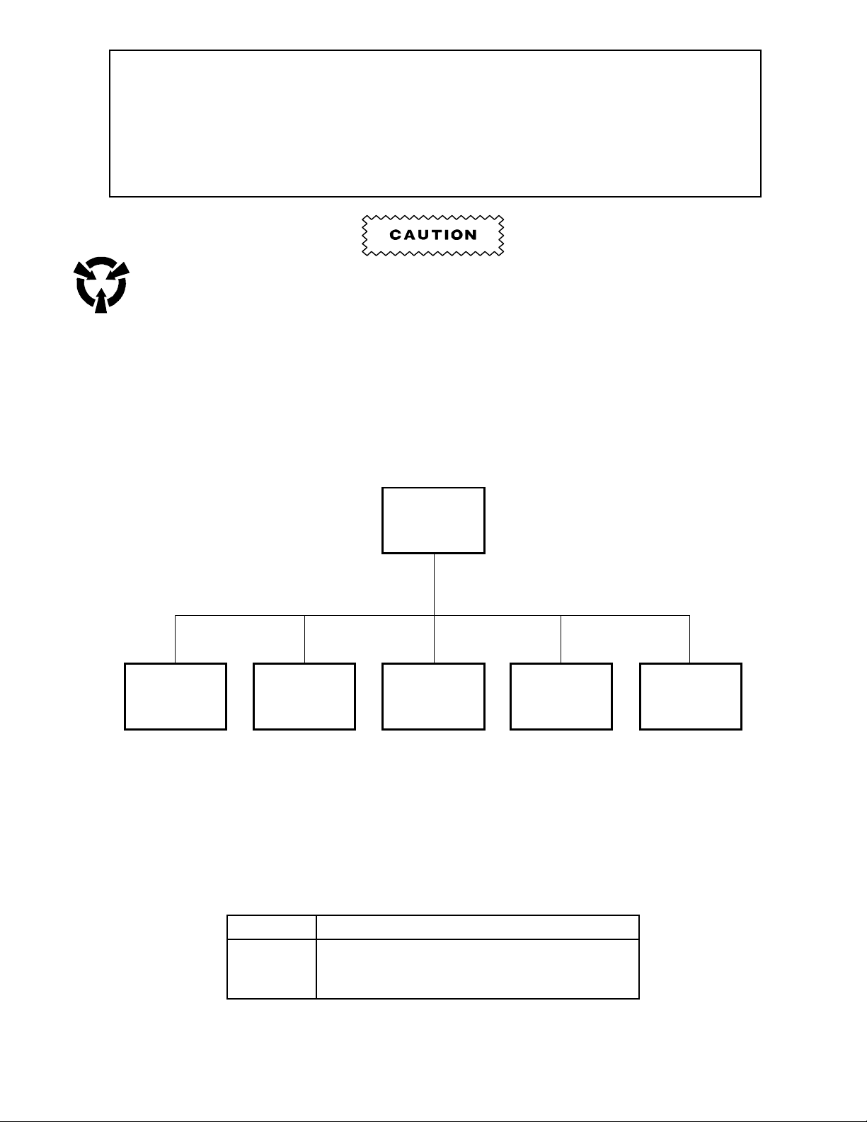
Unpacking the Processor
[1] Remove the PACKING CARTON.
[2] Remove and keep the boxes and bags of
parts.
[3] Check the parts with the Packing List as you
unpack.
[4] Remove the:
• TOP COVER
• 2 SIDE PANELS
• PACKING MATERIAL
• DETECTOR CROSSOVER ASSEMBLY
• 2 CROSSOVER ASSEMBLIES
• DRYER ASSEMBLY
• 3 RACKS
RACK (3)
CROSSOVER
ASSEMBLY (2)
DRYER
ASSEMBLY
FEED SHELF
DETECTOR
CROSSOVER
ASSEMBLY
PACKING MATERIAL
SHIPPING
BASE
H112_0066CCA
H112_0066CC
H112_0120BCA
H112_0120BA
981159 5
Page 6
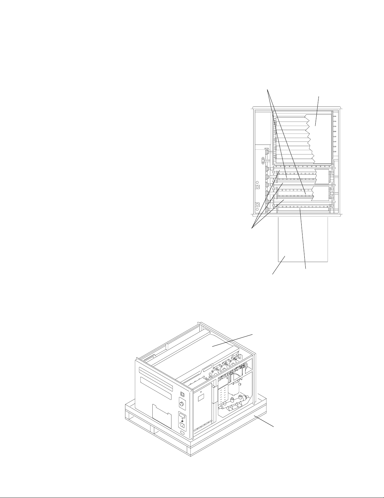
[5] From the DRYER ASSEMBLY, remove the:
• top and bottom COVERS
• PACKING MATERIAL
[6] Install the top and bottom COVERS on the DRYER ASSEMBLY.
Avoid lifting the HEAT EXCHANGERS when removing the PACKING MATERIAL from inside the
TANKS or the fittings may crack.
[7] Carefully remove the PACKING MATERIAL from the TANKS.
COVER
DRYER ASSEMBLY
HEAT EXCHANGER (2)
PACKING MATERIAL
TANK (3)
H112_0064BCB
H112_0064BA
H112_0119BCA
H112_0119BA
6 981159
Page 7

Checking the Parts
[1] Before starting the processor installation, check that you have all the parts listed below.
Packed In or Prepack Box Quantity
Is Already On the Processor Quantity
Cover Assembly 1
Side Panel Assembly 2
Detector Crossover Assembly 1
Fixer/Wash Crossover Assembly 1
Developer/Fixer Crossover Assembly 1
Developer Rack Assembly 1
Fixer Rack Assembly 1
Wash Rack Assembly 1
Bin - Receiving 1
Deflector - Bin 1
Feed Shelf Assembly 1
Gasket - Light Lock 1
Manual Binder 1
Support - Rack 1
Weir - Developer, red 1
Weir - Fixer, blue 1
Weir - Wash, beige 1
Dryer Rack Assembly 1
Wrapped in Paper Quantity
Cover - Evaporation 2
Guard - Splash 1
Tray - Drip 1
Prepack Plastic Bag Prepack Plastic Bag
for an M35A Processor Quantity for an M35 Processor Quantity
Bolt - Hook 2 Bolt - Hook 2
Cartridge - Filter 1 Bracket - Strain Relief, 220 volt only 1
Clamp - Hose, large 2 Cartridge - Filter 1
Clamp - Hose, small 6 Clamp - Hose, large 2
Elbow - Exhaust 1 Clamp - Hose, small 6
Elbow - Hose 1 Elbow - Hose 1
Fastener - Bin 2 Fastener - Bin 2
Guide - Film, right 1 Guide - Film, right 1
Nut - No. 8, 32 3 Nut - No. 8, 32 3
Nut - No. 10, 32 4 Nut - No. 10, 32 4
Plate - Floor 4 Plate - Floor 4
Receptacle - Polarized 1 Relief - Strain, 220 volt only 1
Screw - No. 8, 32 x 5/16 1 Screw - No. 8, 32 x ⁄
Screw - No. 8, 32 x ⁄
Screw - No. 10, 32 x ⁄
Screw - No. 10, 32 x ⁄
3
8
3
8
1
2
3 Screw - No. 10, 32 x ⁄
2 Screw - No. 10, 32 x ⁄
4 Sprocket - 19-Tooth, 50 Hz 1
3
8
3
8
1
2
Sprocket - 19-Tooth, 50 Hz 1 Strainer Assembly 2
Strainer Assembly 2 Strip - Data 1
Washer - Flat 4 Washer - Flat 4
Washer - Hook 2 Washer - Hook 2
Washer - Lock, No. 8 3 Washer - Lock, No. 8 3
Washer - Lock, No. 10 6 Washer - Lock, No. 10 7
Washer - No. 8 3 Washer - No. 8 3
Washer - No. 10 6 Washer - No. 10 7
Tie - Wire 2
3
3
4
981159 7
Page 8
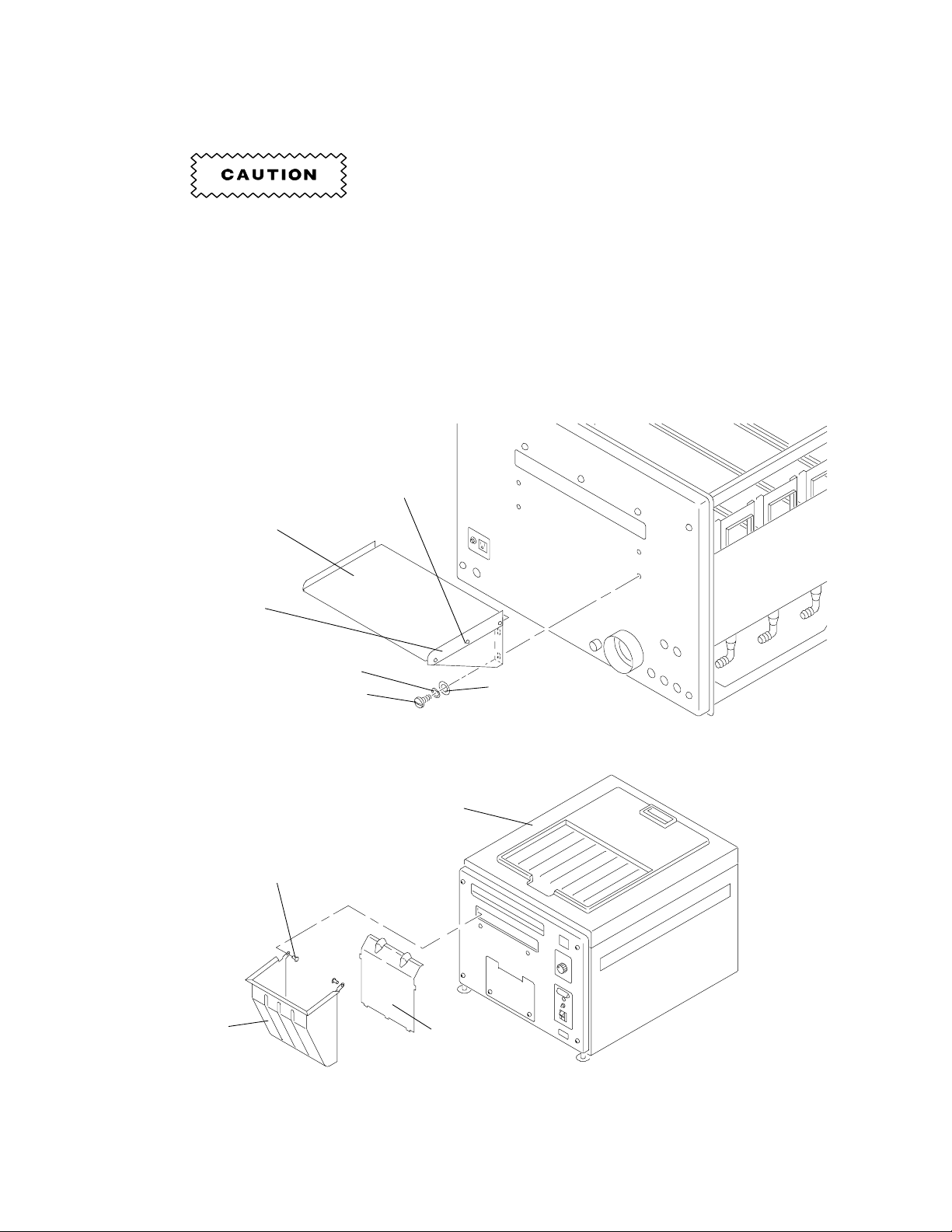
Preparing the Processor for Installation
Installing the Feed Shelf, the Detector Crossover Assembly, and the Developer Rack
[2] Install the:
• FILM GUIDE
Do not overtighten the SCREWS.
[1] Install the:
• FEED SHELF
• 4 WASHERS - No. 10
• 4 LOCK WASHERS - No. 10
• 4 SCREWS - No. 10, 32 x ⁄
FEED SHELF
1
2
SCREW (3)
• 3 SCREWS - No. 8, 32 x ⁄
• 3 WASHERS - No. 8
• 3 LOCK WASHERS - No. 8
• 3 NUTS - No. 8, 32
[3] Install the DEFLECTOR in the RECEIVING
BIN.
[4] Install the RECEIVING BIN on the processor
using the 2 BIN FASTENERS.
3
8
H112_0113BCB
H112_0113BA
RECEIVING
BIN
FILM GUIDE
LOCK WASHER (4)
BIN FASTENER (2)
SCREW (4)
TOP COVER
DEFLECTOR
WASHER (4)
H112_0151BCA
H112_0151BC
8 981159
Page 9

[5] Install the 3 WEIRS.
[6] Install the RACK SUPPORT on the non-drive
side of the processor with the 2 No. 10
WASHERS, LOCK WASHERS, and
SCREWS.
WEIR (3)
[7] Install the DEVELOPER RACK.
[8] Pull the RACK SUPPORT to the non-drive
side of the processor.
[9] Check the clearance by removing the WEIRS
and the DEVELOPER RACK.
[10] Move the RACK SUPPORT, if necessary.
[11] Tighten the 2 SCREWS on the RACK
SUPPORT.
[12] Install the DEVELOPER RACK, the WEIRS,
and the DETECTOR CROSSOVER
ASSEMBLY.
SCREW (2)
LOCK
WASHER (2)
WASHER (2)
O-RING
RACK
SUPPORT
H112_0146CCB
H112_0146CA
SCREW (2)
RACK
SUPPORT
WEIR (3)
DEVELOPER RACK
DETECTOR
CROSSOVER
ASSEMBLY
H112_0150DCA
H112_0150DA
981159 9
Page 10
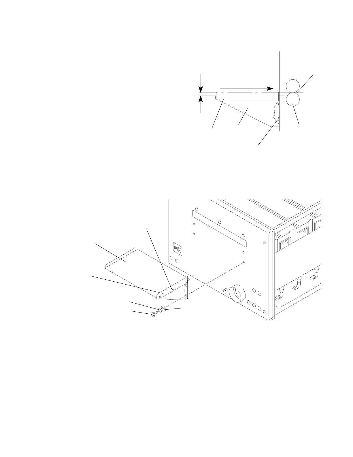
Adjusting the Feed Shelf
1.5 mm
(0.06 in.)
H112_0090AA
H112_0090ACA
GUIDE
FILM
SHELF
FEED
SCREW (4)
ROLLERS
CROSSOVER
DETECTOR
NIP
film entry path
[1] Adjust the height of the FEED SHELF to
approximately 1.5 mm (0.06 or 1/16 in.) below
the NIP of the DETECTOR CROSSOVER
ROLLERS.
(a) Loosen the 4 SCREWS.
(b) Adjust the FEED SHELF for the correct
height by moving the FEED SHELF up
or down.
(c) Insert a sheet of 35 x 43 cm film into
the NIP of the DETECTOR
CROSSOVER ROLLERS.
[2] Use the edges of the film to align the FILM
GUIDE with the DETECTOR CROSSOVER
ROLLERS for squareness.
[3] Tighten the 4 SCREWS.
FEED SHELF
FILM GUIDE
H112_0113BCB
H112_0113BA
LOCK WASHER (4)
SCREW (4)
SCREW (3)
WASHER (4)
10 981159
Page 11
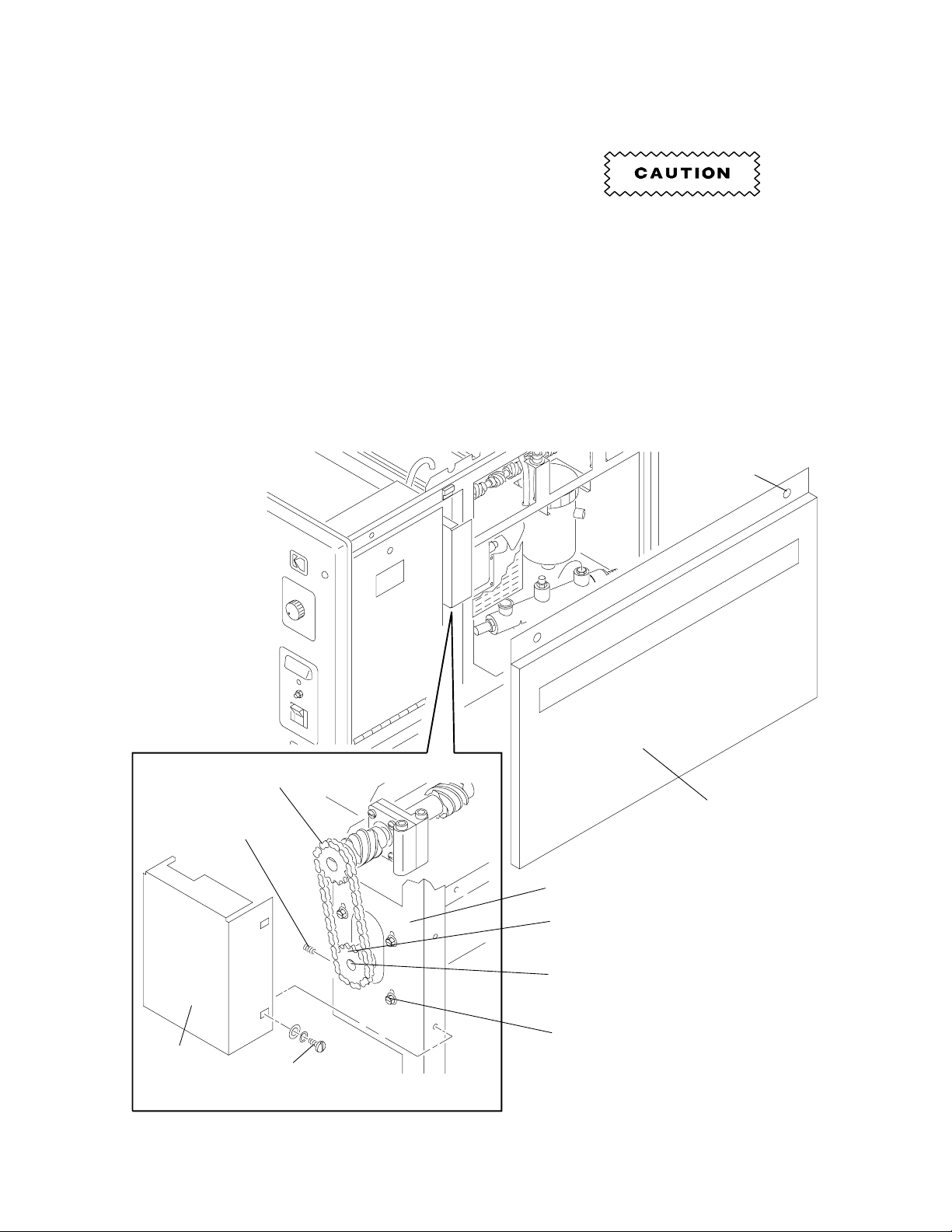
Changing to 50 Hz Operation
[1] Loosen the 2 SCREWS and remove the drive [10] Check that the DRIVE CHAIN does not touch
SIDE PANEL. the MOUNTING PLATE.
[2] Remove the 2 GUARD SCREWS and the
CHAIN GUARD.
[3] Loosen the 4 MOUNTING SCREWS.
[4] Remove the DRIVE CHAIN.
Do not overtighten the MOUNTING
SCREWS. Tighten only until the
[5] Loosen the SETSCREW.
[6] Remove the existing 16-TOOTH SPROCKET
from the MOTOR SHAFT.
RUBBER ISOLATORS, not shown, on
the MOUNTING SCREWS are partially
seated.
[7] Install the new 50 Hz 19-TOOTH SPROCKET
on the MOTOR SHAFT.
[8] Tighten the SETSCREW.
[9] Install the DRIVE CHAIN.
DRIVE CHAIN
SETSCREW
[11] Tighten the 4 MOUNTING SCREWS.
[12] Install the CHAIN GUARD and the 2 GUARD
SCREWS.
[13] Install the SIDE PANEL.
SCREW (2)
SIDE
PANEL
MOUNTING PLATE
16-TOOTH SPROCKET
MOTOR SHAFT
MOUNTING SCREWS (4)
CHAIN
GUARD
GUARD
SCREW (2)
H112_0149DCA
H112_0149DA
981159 11
Page 12
Installing the Processor
H112_0148CA
H112_0148CCA
PROCESSOR
LEVELING
SCREW
(4)
MOUNTING
STAND
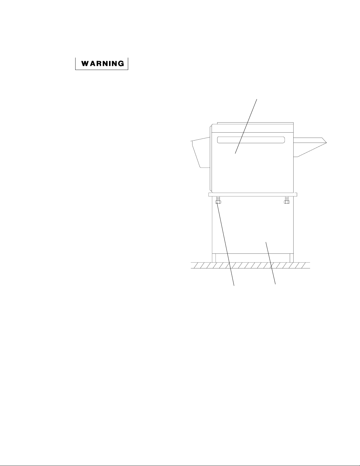
Installing the Processor onto a Base
The processor weighs 90 kg (200 lb).
Use qualified personnel to install this
processor.
[1] Remove the processor from the SHIPPING
BASE. See the illustration on page 5.
[2] Remove the 4 LEVELING SCREWS from the
processor.
[3] Install the processor on a stable, flat surface
or on a KODAK
Stand, CAT No. 808 1176.
[4] Install the LEVELING SCREWS through the
MOUNTING STAND or the stable, flat
surface.
M35
X-OMAT Mounting
12 981159
Page 13

H112_0129CA
Dark Room
5 cm
(2 in.)
Offset
56 cm
(22 in.)
Opening
in wall
46 cm
(18 in.)
Plywood
opening
Leave flexibility
in this dimension
to allow for
leveling
of processor
H112_0129CCA
GASKET
LIGHT LOCK
cover wall opening
frame, large enough to
20 mm (0.75 in.) plywood
Installing the Processor Through a Wall
NOTE
The processor may be installed with either the FEED SHELF or the RECEIVING BIN through the wall.
Dark Room
20 cm
(8 in.)
Offset
LIGHT LOCK
GASKET
71 cm
(28 in.)
Opening
in wall
46 cm
(18 in.)
Plywood
opening
Leave flexibility
in this dimension
to allow for
leveling
of processor
20 mm (0.75 in.)
plywood frame,
large enough to
cover wall opening
H112_0128CCA
H112_0128CA
Wall Installation Wall Installation
with the Receiving Bin through the Wall with the Feed Shelf through the Wall
981159 13
Page 14

• The processor weighs 90 kg (200 lb). Use qualified personnel to install this processor.
• Do not pull the LIGHT LOCK GASKET too tight.
[1] Install the LIGHT LOCK GASKET to the PLYWOOD FRAME. Do not stretch the LIGHT LOCK GASKET.
LIGHT LOCK GASKET
around opening
and attached to
plywood frame
20 mm
(0.75 in.)
plywood
61 cm (24 in.)
frame to
cover wall
opening
46 cm
(18 in.)
HOOK BOLT (2)
HOOK
WASHER (2)
HOOK
NUT (4)
48.7 cm
(19.18 in.)
2.5 cm (1.0 in.)
1.4 cm (.56 in.)
LEVELING
SCREW (4)
FLOOR PLATE (4)
H112_0130DCA
H112_0130DA
14 981159
Page 15

Leveling the Processor
2.5 cm
(1.00 in.)
H112_0133AA
H112_0133ACA
FLOOR PLATE (4)
LEVELING
SCREW
(4)
[1] Move the processor into position.
[2] Install the 4 FLOOR PLATES under the
LEVELING SCREWS or under the
MOUNTING STAND.
NOTE
If an M35 MOUNTING STAND is used,
bolt the processor to the MOUNTING
STAND and level the MOUNTING
STAND.
[3] Level the processor side-to-side and
end-to-end.
[4] Install the 2 HOOK BOLTS around the front
2 LEVELING SCREWS and through the wall.
See the illustration on page 15.
[5] Install the 4 HOOK NUTS and the 2 HOOK
WASHERS on the 2 HOOK BOLTS.
LEVEL
H112_0126BCA
H112_0126BA
981159 15
Page 16

Installing Seismic Brackets
IMPORTANT
Local building codes may require that SEISMIC BRACKETS be used.
[1] Install SEISMIC BRACKETS to the processor or to the MOUNTING STAND if required by local codes. A
Seismic Bracket Kit, Part No. 261413, is available.
SEISMIC BRACKET KIT
LEVELING
SCREW
(4)
FLOOR
PLATE
(4)
H112_0134DCA
H112_0134DA
16 981159
Page 17

Connecting the Plumbing
• Use local codes when installing the FLOOR DRAIN.
• Do not use brass or copper for the FLOOR DRAIN. Use PCV or cast iron.
• Do not make a solid connection to the FLOOR DRAIN. Use an open FLOOR DRAIN with a minimum
clearance of 2.5 cm (1 in.) between the tubing from the processor and the FLOOR DRAIN.
[1] Check that the developer and fixer WEIRS are installed correctly.
[2] Use ⁄
[3] Connect the incoming water supply to the WATER INLET of the processor.
1
-inch (1.27 cm) ID tubing, Part No. 760476, to connect the developer, fixer, and wash DRAINS to
2
the FLOOR DRAIN. See the illustration on page 20. Order the tubing by the foot.
WEIRS
wash
WATER INLET
DRAIN (3)
wash
fixer
developer
fixer
developer
H112_0071DCB
H112_0071DA
981159 17
Page 18

Connecting the Replenishment Tanks to the Replenishment Pump
[1] Check that the connections in the tubing are
tight.
• Do not allow water in the tubing from
the REPLENISHMENT TANKS.
• The highest solution level in the
REPLENISHMENT TANKS must be below
the solution level in the processor TANKS.
• Maximum processor solution level is 97 cm
(38 in.) with the processor installed on an
M35 MOUNTING STAND.
[2] Install the 2 STRAINERS in the tubing
between the REPLENISHMENT PUMP and
the REPLENISHMENT TANKS. Use the ⁄
3
in.
8
(9.5 cm) TUBING supplied.
[3] Connect the tubing to the processor TANKS.
[4] Check that the REPLENISHMENT TANKS are
connected to the correct processor TANKS.
REPLENISHMENT TANKS
Installing the Silver Recovery Unit
[1] Connect the SILVER RECOVERY UNIT to the
fixer DRAIN with ⁄
1
-inch (1.27 cm) ID tubing.
2
STRAINERS
OUT
FLOOR DRAIN
H104_0026BCB
IN
SILVER RECOVERY UNIT
H112_0118AC
18 981159
Page 19

Connecting the Exhaust Hose
Clearance for
Exhaust Duct
H104_0005AA
Environmental Requirements
The building ventilation system must
draw air to the outside of the building,
so that no air is reused.
[1] Connect a 7.6 cm (3 inch) EXHAUST HOSE,
EXHAUST
DUCT
5 cm (2 in.)
maximum
not supplied, to the EXHAUST ADAPTER.
[2] Connect the EXHAUST HOSE to the
EXHAUST DUCT from the building ventilation
system.
[3] Leave a 5 cm (2 inch) air gap between the
EXHAUST
HOSE
EXHAUST HOSE and the EXHAUST DUCT.
IMPORTANT
• If the venting is not correct, fumes will corrode equipment and cause artifacts. Do not install the
processor or accessories if the venting is not correct.
• The building ventilation system must draw air to the outside of the building, so that no air is reused.
• The AIR FLOW is correct when the fumes are flowing out of the processor through the EXHAUST
HOSE. Before installing the processor, or at the next service call, do the following to check that the
AIR FLOW is correct.
H104_0005ACA
EXHAUST ADAPTER
H112_0071BCB
H112_0071BA
981159 19
Page 20

Checking the Ventilation
Do the following procedure, using an AIR METER TL-2431, to check that the venting is correct.
[1] If the processor is installed, deenergize the processor.
[2] Disconnect the EXHAUST HOSE from the processor EXHAUST ADAPTER.
[3] Place the RUBBER HOSE on the CENTER CONNECTOR of the AIR METER.
[4] If a replenishment J TUBE, Part No. 592380, is available, do the following. If not, advance to Step 5.
(a) Cut off and discard the curved portion of the replenishment J TUBE.
(b) Install the tapered end of the replenishment J TUBE into the RUBBER HOSE.
(c) Advance to step 7.
[5] If a replenishment J TUBE is not available, align a HOSE SUPPORT, such as a straightened coat
hanger, next to the RUBBER HOSE. The ends of the HOSE SUPPORT and the RUBBER HOSE must
be together.
[6] Place TAPE around the HOSE SUPPORT and the RUBBER HOSE at 3 points. See the illustration.
IMPORTANT
The TAPE should not inhibit the AIR FLOW through the RUBBER HOSE.
[7] Insert the replenishment J TUBE or the RUBBER HOSE into the EXHAUST HOSE until the end is 30 cm
(12 in.) from the end of the EXHAUST HOSE.
IMPORTANT
The RUBBER HOSE or J TUBE must be in the center of the EXHAUST DUCT.
[8] Hold the AIR METER vertical, and record the average of several readings.
AIR FLOW
30 cm
(12 in.)
EXHAUST HOSE
RUBBER HOSE or
MODIFIED J TUBE
TAPE (3 places)
HOSE SUPPORT
CENTER CONNECTOR
AIR METER
H048_0118BCA
H048_0118BA
20 981159
Page 21

[9] Compare the average reading with the table:
Clearance for
Exhaust Duct
H104_0005AA
Table 1 Measuring the Static Pressure
Negative Static Pressure, Water Head
Duct Diameter MIN MAX
76 mm (3 in.) 0.76 mm (0.03 in.) 1.02 mm (0.04 in.)
102 mm (4 in.) 0.25 mm (0.01 in.) 0.51 mm (0.02 in.)
[10] Adjust one of the following to obtain the
required reading:
(a) the damper (or fan) in the building
ventilation system or
(b) the clearance between the EXHAUST
DUCT and the EXHAUST HOSE to
5 cm (2 inches); see the illustration.
[11] If the AIR FLOW reading is still not correct,
contact the sales representative and the
customer to correct the venting.
[12] When the AIR FLOW reading is the same as
the measurements in the table, connect all the
hoses.
[13] If the processor has been installed, install the
COVERS and PANELS on the processor.
5 cm (2 in.)
maximum
EXHAUST
DUCT
EXHAUST
HOSE
H104_0005ACA
IMPORTANT
• Inform the customer that all COVERS and PANELS must be installed while the processor is
energized.
• If the processor is installed through the darkroom wall, it is most important that the air pressure in the
darkroom is greater than the air pressure of the area surrounding the darkroom. For example, the air
in a 3 m3 (10 ft3) room should change 10 times per hour.
[14] Do the following to check the AIR FLOW at the FEED SHELF:
(a) If the processor is installed, deenergize the processor.
(b) Hold a piece of tissue paper in front of the FEED SHELF.
NOTE
The AIR FLOW should be toward the processor.
(c) If the tissue paper moves away from the processor, call Customer Service for Health Sciences
Monday through Friday from 8:00 a.m. to 5:00 p.m. Rochester, New York, time at (716) 724-1789.
Then press ‘‘1’’.
981159 21
Page 22

Connecting the Main Power for an M35A Processor,
H112_0089AC
MAIN POWER SWITCH
TOP COVER
H112_0089ACB
120 Volts Only
• Dangerous voltage.
• Possible damage from electrostatic
discharge.
[1] Check and use the Local Electrical Codes.
[2] Consult with the customer about installing the
POLARIZED RECEPTACLE.
[3] Turn off the power to the wall outlet where the
POLARIZED RECEPTACLE will be installed.
[4] Install, or have the customer install, the
POLARIZED RECEPTACLE.
NOTE
The COVER PLATE is not supplied.
[5] Move the MAIN POWER SWITCH on the
processor to the ‘‘OFF’’ position.
[6] Plug the POWER CORD into the POLARIZED
RECEPTACLE.
POLARIZED
RECEPTACLE,
M35A Processor
only
POWER
CORD
H112_0122BCB
H112_0122BA
22 981159
Connecting the Main Power to an M35A Processor
Page 23

Connecting the Power Cord on an M35 Processor,
220 Volts Only
• Dangerous voltage.
• Possible damage from electrostatic
discharge.
[1] Check and use the Local Electrical Codes.
[2] Disconnect the main power at the wall.
[3] Move the MAIN POWER SWITCH to the
‘‘OFF’’ position.
[4] Remove the TOP COVER and the drive SIDE
PANEL, not shown.
[5] Open the ELECTRICAL BOX DOOR.
[6] Move wire No. 8A to the correct terminal on
TB5.
[7] Move JUMPER 8:
[8] Apply the correct DATA STRIP inside the
ELECTRICAL BOX DOOR to indicate the
correct supply voltage.
[9] Install the STRAIN RELIEF BRACKET inside
the processor. See the illustration below.
[10] Feed the CABLE through the FRONT PANEL.
[11] Insert the CABLE through the STRAIN
RELIEF.
[12] Install the STRAIN RELIEF to the STRAIN
RELIEF BRACKET with the NUT.
[13] Feed the CABLE into the ELECTRICAL BOX.
[14] Connect the incoming wires to L1, L2, and N
of TB1. See the connection charts on the
circuit diagrams on pages 29 and 30.
[15] Connect the ground wire to the GROUND
LUG. See the illustration on the next page.
Volts Jumper 8
200 or 208 TB5-2
220 TB5-3 COVER.
240 TB5-4
FRONT PANEL
Position of
ELECTRICAL BOX
[16] Install the 2 WIRE TIES to the CABLE and
the STRAIN RELIEF.
[17] Close the ELECTRICAL BOX DOOR.
[18] Install the drive SIDE PANEL and the TOP
STRAIN RELIEF
CABLE
NUT
STRAIN
RELIEF
BRACKET
H112_0162BCA
H112_0162BA
981159 23
Page 24

TB5
TB1
GROUND
LUG
ELECTRICAL BOX DOOR
DATA STRIP
H112_0086ECB
H112_0086EC
Connecting the 220 Volt Power Cord
24 981159
Page 25

Circuit Diagrams
981159 25
Page 26

.
26 981159
Page 27

Preparing the Processor for Use
Checking the Tubing Clamps, Tanks, and Racks
[1] Tighten and check all CLAMPS. [3] Fill the 3 TANKS with water.
[4] Run the processor for a few minutes.
[5] Check for leakage.
Check all CLAMPS 2 - 4 weeks after
installing any new tubing. Tighten the
CLAMPS if necessary. Although a
CLAMP may be tight when tubing is
installed, temperature changes or
shrinkage of the plastic tubing will
cause the CLAMP to loosen.
[2] Check that the 3 WEIRS are installed and
fully seated:
red in the developer TANK
blue in the fixer TANK
beige in the wash TANK
WEIR (3)
[6] Drain the processor completely.
[7] Rinse the DEVELOPER, FIXER, and WASH
RACK ASSEMBLIES with warm water.
[8] Rotate the ROLLERS manually.
[9] Check that the ROLLERS rotate fully.
[10] Check that all the moving parts engage
correctly.
TANK (3)
WATER
INLET
TUBE
H112_0070DCA
H112_0070DA
981159 27
Page 28

Filling the Tanks
H112_0093CA
CAP
O-RING
DEVELOPER
FILTER
FILTER
HOUSING
H112_0093CCB
[1] Soak the DEVELOPER FILTER for
30 seconds in warm water.
[2] Insert the DEVELOPER FILTER into the
FILTER HOUSING.
[3] Check that the O-RING is seated correctly, or
leakage may occur.
[4] Tighten the CAP and install the FILTER
HOUSING in the processor.
[5] Check that the tubing is not kinked.
• Mix the developer first, then the fixer.
• Wash the mixing equipment thoroughly
between solutions to avoid contamination of
the solutions.
• Rinse the mixing and filling equipment
before each use.
• Fill the FIXER TANK first.
[6] Install the SPLASH GUARD between the
DEVELOPER TANK and the FIXER TANK.
SPLASH
GUARD
H112_0117ACA
H112_0117AC
Splash Guard Installed Between the Developer
and Fixer Tanks
28 981159
Page 29

[7] To fill the processor FIXER TANK, add fixer
H112_0014AC
LINES
FILL
TANK
DEVELOPER
TANK
FIXER
TANK
WASH
WEIRS
H112_0014ACC
H112_0114AC
H112_0114ACB
GRADUATE
DISCONNECT
QUICK
TUBING
LATCH
METAL
replenisher until the solution is at the higher
FILL LINE on the blue WEIR.
[8] Remove and rinse the SPLASH GUARD.
[9] Install the SPLASH GUARD over the FIXER
TANK.
[10] To fill the processor DEVELOPER TANK:
(a) Fill the DEVELOPER TANK half full of
developer replenisher from the
replenishment tank.
(b) Add 190 mL (6.5 fl oz) of KODAK
X-OMAT Developer Starter.
(c) Fill the DEVELOPER TANK to the
higher FILL LINE on the red WEIR with
developer replenisher.
[11] Remove the SPLASH GUARD and rinse
thoroughly.
[12] Allow the developer to reach the operating
temperature before processing any film.
Checking the Replenishment Flow Rates
[1] Remove the TOP COVER.
[2] Lift the top DETECTOR ROLLER of the
DETECTOR ASSEMBLY.
NOTE
The REPLENISHMENT PUMP will
continue to operate for 3 seconds after
releasing the DETECTOR ROLLER.
RP
[3] Check that the replenisher solutions flow
freely through the TUBING along the drive
side of the processor.
[4] Press the METAL LATCH of the red QUICK
DISCONNECT of the developer to disconnect
the developer TUBING.
[5] Pull the TUBING slightly by rotating the
TUBING over the edge of the frame.
[6] Insert the TUBING into a GRADUATE.
981159 29
Checking the Replenishment Flow Rates
Page 30

[7] Lift the top DETECTOR ROLLER of the DETECTOR ASSEMBLY for the correct time, for 28 or
34 seconds. See the table below.
[8] Check that the amount of developer in the GRADUATE is the same as in the table below.
[9] Adjust the REPLENISHMENT PUMP if necessary. See page 36 for the adjustment procedure.
[10] Repeat steps 7 - 9 if necessary.
[11] Connect the QUICK DISCONNECT.
[12] Repeat this procedure with the fixer TUBING to check the flow rate of the fixer.
Replenishment Flow Rate
Average Amount mL per 35 cm mL per 43 cm
of Film (14 in.) 28 sec (17 in.) 34 sec
Film Size Use per 8 Hours of of Film Travel of Film Travel
Processed Condition Processor Operation Developer Fixer Developer Fixer
Only 35 x 35 cm High 90 sheets or more 50 70 .
(14 x 14 in.) film Medium 60 sheets 65 85 -- --
Low 30 sheets or less 80 100
Average size High 115 sheets or more 50 70 .
film intermix Medium 80 sheets 65 85 -- --
Low 40 sheets or less 80 100
Only 43 x 35 cm High 75 sheets or more . 60 85
(17 x 14 in.) film Medium 50 sheets -- -- 80 100
Low 25 sheets or less 100 120
NOTE
• KODAK
• Replenishment rates are based on one sheet of film.
• Film feeding orientation should be consistent for best results.
• Slight sensitometric changes will occur as subsequent films are processed through a freshly started
process. This is known as ‘‘seasoning’’ and is normal with any photographic process. Process control
aims may have to be adjusted slightly to compensate.
• For 30 sheets or less, flooded replenishment is recommended.
RP
X-OMAT Chemicals are recommended.
30 981159
Page 31

Adjusting the Replenishment Pump
H112_0115AC
H112_0115ACC
BRACKET
SCREW (2)
PUMP COVER
TOP COVER
[1] Remove the TOP COVER and the
RECEIVING BIN.
[2] Loosen the 2 SCREWS and remove the
PUMP COVER.
[3] Actuate the DETECTOR SWITCH by lifting
the top DETECTOR ROLLER of the
DETECTOR CROSSOVER ASSEMBLY until
the ADJUSTMENT SCREW is visible through
the hole in the BRACKET.
[4] Loosen the SETSCREW.
Do not adjust the LOCKNUT on the
other end of the ADJUSTMENT
SCREW.
[5] Rotate the ADJUSTMENT SCREW to adjust [8] Install the TOP COVER and the PUMP
the flow rate. COVER.
clockwise to increase the flow
rate
counterclockwise to decrease the flow
rate
[6] Tighten the SETSCREW.
[7] Check the flow rates and do steps 2 - 6 again
if necessary. See the table on page 35 for
various replenishment rates.
REPLENISHMENT PUMP
ADJUSTMENT
SCREW
SETSCREW
Do not
adjust!
LOCKNUT
H112_0030BCB
H112_0030BC
[9] Feed a sheet of film into the processor to
check that the REPLENISHMENT PUMPS
operate correctly. See the adjustment
procedure for the Detector Switches in the
Service Manual, Part No. 981777, if
necessary.
ADJUSTMENT SCREW
DECREASE INCREASE
BRACKET
HOLE
OUTPUT
981159 31
Page 32

Installing the Racks
H112_0164CC
ASSEMBLY
CROSSOVER
DETECTOR
CROSSOVER ASSEMBLY
DEVELOPER/FIXER
ASSEMBLY
CROSSOVER
FIXER/WASH
RACK
FIXER
RACK
WASH
ASSEMBLY
DRYER
RACK
DEVELOPER
H112_0164CCA
[1] Install the RACKS in the correct TANKS.
[2] Install the:
Use the DRIP TRAY and SPLASH
GUARD when you install or remove
the RACKS. Lower the RACKS slowly.
Seat them firmly.
NOTE
The WASHER on the top of the drive
side of the DEVELOPER RACK has a
‘‘D’’ on it. The one on the FIXER
RACK has an ‘‘F’’. The RACKS may
also have red, blue, and white wire ties
for easy identification.
red DEVELOPER RACK
blue FIXER RACK
white WASH RACK
• DEVELOPER/FIXER CROSSOVER
ASSEMBLY
• FIXER/WASH CROSSOVER ASSEMBLY
• DETECTOR CROSSOVER ASSEMBLY
• DRYER ASSEMBLY
• EVAPORATION COVERS, not shown
DRIP TRAY
SPLASH GUARD
H112_0015ACA
H112_0015AC
32 981159
Page 33

Checking the Operation of the Processor
H112_0089AC
H112_0089ACE
DRYER
TEMPERATURE
CONTROL
KNOB
RUN/STANDBY
SWITCH
TEMPERATURE
READY LIGHT
TOP COVER
SIDE
PANEL
(2)
[1] Turn on the water supply.
[2] Energize the processor.
[3] Check that the:
• Developer and fixer have agitation
• No leakage occurs
• Solutions overflow into the WEIRS
• Water flows into the processor
[4] Install the 2 SIDE PANELS and the TOP
COVER.
[5] Check the operation of the RUN/STANDBY
SWITCH.
[6] Set the DRYER TEMPERATURE CONTROL
KNOB to the minimum temperature necessary
to provide dry film.
[7] Check that warm air is coming out of the
exhaust.
[8] When the TEMPERATURE READY LIGHT blinks, insert a THERMOMETER of known accuracy, such as
NOTE
The processor is now in the run mode.
Part No. 761217, into the DEVELOPER TANK on the non-drive side between the SIDE PLATE of the
DEVELOPER RACK and the RACK SUPPORT.
Insert THERMOMETER
here
H112_0121BCA
H112_0121BA
981159 33
Page 34

Possible damage from electrostatic discharge. Use the POTENTIOMETER ADJUSTING TOOL
TL-1481 to prevent damage to the 100 CIRCUIT BOARD.
[9] Check that the temperature is 33.3°C (92°F). If not, use TL-1481 to rotate R2 on the 100 CIRCUIT
BOARD:
clockwise to increase the temperature
counterclockwise to decrease the temperature
[10] With the DRYER and developer at the correct temperature, feed 3 or 4 test films to check the operation
of the DETECTOR SWITCHES and the REPLENISHMENT PUMP.
100 CIRCUIT BOARD
R2
R1
Adjusting the Developer Temperature
ELECTRICAL
BOX
H112_0087BCB
H112_0087BC
34 981159
Page 35

[11] To check the time required to process a sheet of film (Clear Time) do the following:
(a) With the TEMPERATURE READY LIGHT blinking, press one of the RUN/STANDBY SWITCHES.
(b) The processor should operate (run mode) for 3 minutes.
(c) If an adjustment is necessary, turn R1 on the 100 CIRCUIT BOARD clockwise to increase
and counterclockwise to decrease the cycle.
NOTE
The processor will remain in the standby mode when not in use, but will go into the run mode
every 8 to 10 seconds if the temperature in the DRYER is not at the reading of the
THERMOSTAT.
RUN/STANDBY
SWITCH
H112_0002DCA
H112_0002DC
981159 35
Page 36

New Equipment Warranty
Kodak warrants this KODAK
initial installation, when installed within 1 year from the date of shipment.
Warranty Repair Coverage
If this equipment does not function properly during the waranty period, the Dealer in KODAK X-OMAT
Processors who sold the equipment will provide or arrange for repair of the equipment during the dealer’s
normal working hours. Such repair service will include any necessary adjustments and/or replacement of parts
necessary to maintain your equipment in good working order.
How to Obtain Service
Should equipment require service, refer to the sales contract for details on whom to call for service, or contact
the Dealer in KODAK X-OMAT Processors who sold the equipment.
Limitations
Warranty service is limited to the contiguous United States, the island of Oahu in Hawaii, and certain areas of
Alaska.
This warranty does not cover: circumstances beyond Kodak’s control; misuse; abuse; any attachments,
accessories, alterations not marketed by Kodak, (including service or parts to correct problems resulting from
the use of such attachments, accessories or alterations); failure to follow Kodak’s operating instructions; or
supply items.
M35 or M35A
X-OMAT Processor to function properly for 6 months from date of
Kodak makes no other warranties, express, implied, or of merchantability for this equipment.
Repair without charge is Kodak’s and the Dealer’s only obligation under this warranty.
Kodak will not be
responsible for any consequential or incidental damages resulting from the sales, use, or improper
functioning of this equipment even if loss or damage is caused by the negligence or other fault of
Kodak.
or profit, downtime costs, loss of use of the equipment, cost of any substitute equipment, facilities or services or
claims of your customers for such damages.
This limitation of liability will not apply to claims for injury to persons or damage to property caused by the sole
negligence of fault of Kodak or by persons under its direction or control.
Such damages for which Kodak will not be responsible, include, but are not limited to, loss of revenue
36 981159
Page 37

Publication Change Table
Rev. Date ECO No. PCN No. Pub. No. Affected Pages Description
September 4014-318 1 981159 All Supersedes Publications
1992 No. 635817 and 635038. The
previous installation
instructions for the M35 and
M35A Processors were
combined into one manual,
and the information updated.
.
3047ii_c.txt
981159 37
Page 38

EASTMAN KODAK COMPANY • ROCHESTER, N.Y. 14650Printed in USA
Kodak
and
X-Omat
are trademarks.
Health Sciences Division
 Loading...