

Page 1

Publication No. 981900
Supersedes September 1992
INSTALLATION INSTRUCTIONS
for the
September 1996
Kodak
M35-M and M35A-M
X-Omat
H112_0008AC
PROCESSORS
© Eastman Kodak Company
Page 2
PLEASE NOTE The information contained herein is based on the experience and knowledge relating to the
subject matter gained by Eastman Kodak Company prior to publication.
No patent license is granted by this information.
Eastman Kodak Company reserves the right to change this information without notice, and
makes no warranty, express or implied, with respect to this information. Kodak shall not be liable
for any loss or damage, including consequential or special damages, resulting fromany useof
this information, even if loss or damage is caused by Kodak’s negligence or other fault.
This equipment includes parts and assemblies sensitive to damage from electrostatic
discharge. Use caution to prevent damage during all service procedures.
Warning
To avoid hazardous conditions, keep floors and floor coverings around your
associated drains clean and dry at all times. Any accumulation of fluids from mixing tanks, drain lines, etc, should
be cleaned upimmediately. In the eventof an accumulationof liquid dueto backup, overflow, or other malfunctions
of the drain associated with your
Kodak X-Omat
PROCESSOR, call a plumber or other contractor to correct any
problem with the drain. Kodak accepts no responsibility or liability whatsoever for the serviceability of any drain
connected to or associated with a
Kodak X-Omat
PROCESSOR. Such drains are the sole responsibility of the
customer.
Kodak X-Omat
PROCESSOR and
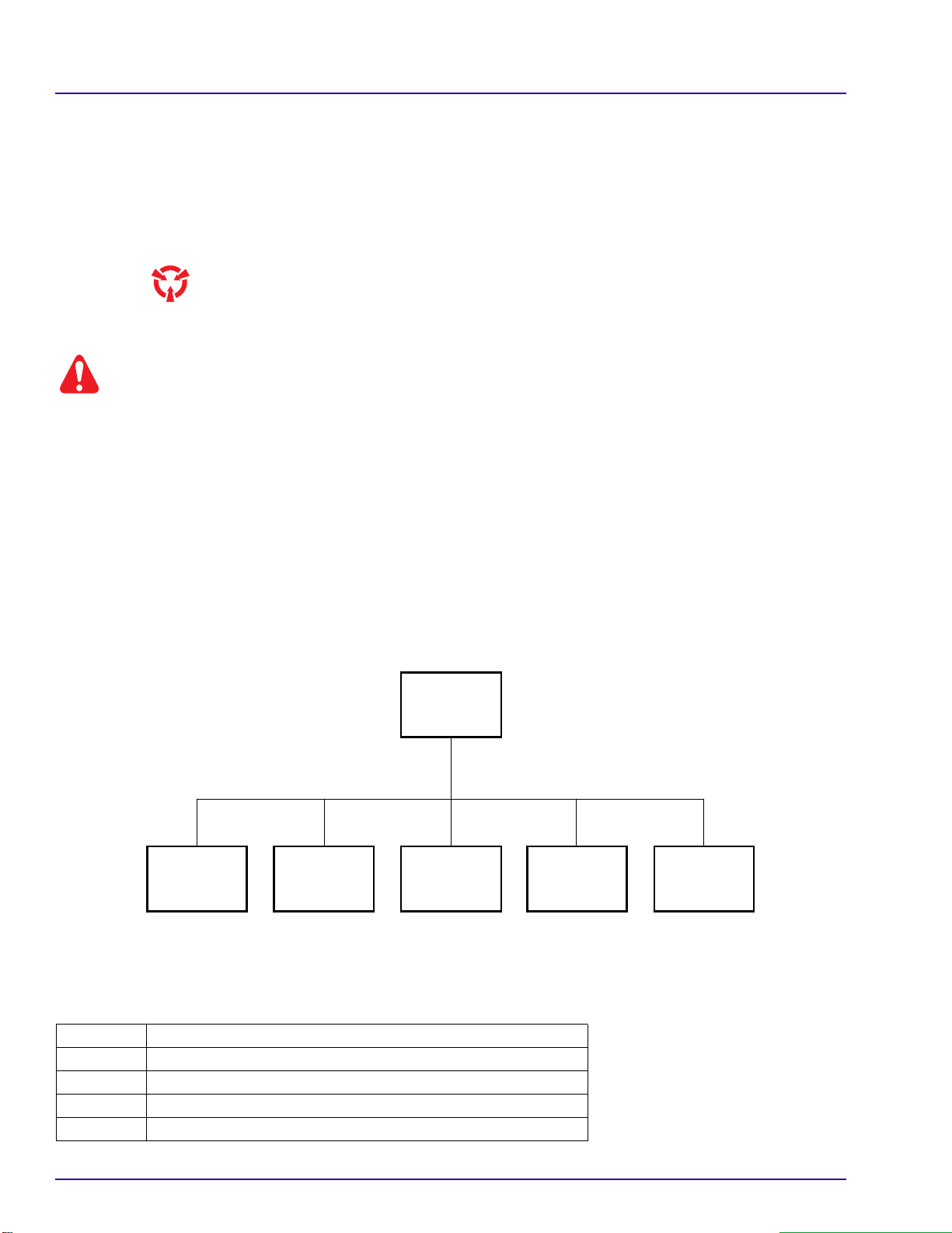
Related Publications for the M35-M and M35A-M PROCESSORS
This publication is part of a series of instruction books that provides technical support information on the
M35-M and M35A-M
X-Omat
PROCESSORS. If you need an adiitionalor replacement publication,order it through
your Eastman Kodak Representative using the Publication Part Numbers below.
COMPLETE
BINDER
981903
OPERATOR
MANUAL
SITE SPECS
981157
INSTALLATION
INSTRUCTIONS
981900
SERVICE
MANUAL
981901981799
PARTS LIST
981902
H112_9003BC
Special Tools Required
Only qualified personnel should install this PROCESSOR. The following tools are required:
Kodak
Part No. Description
TL-2431 Air Meter
TL-1434 Level - approximately 30 cm (12 in.)
TL-1481 Potentiometer Adjusting Tool
1C7639 For M35A-M Processors only, Turnaround Adjustment Tool
2 September 1996 – 981900
Page 3

Table of Contents
Description Page
Electrostatic Discharge . . . . . . . . . . . . . . . . . . . . . . . . . . . . . . . . . . . . . . . . . . . . . . . . . . . 4
Unpacking the PROCESSOR . . . . . . . . . . . . . . . . . . . . . . . . . . . . . . . . . . . . . . . . . . . . . . 5
Preparing the PROCESSOR for Installation . . . . . . . . . . . . . . . . . . . . . . . . . . . . . . . . . . . 8
Installing the PROCESSOR . . . . . . . . . . . . . . . . . . . . . . . . . . . . . . . . . . . . . . . . . . . . . . . 11
Connecting the Plumbing . . . . . . . . . . . . . . . . . . . . . . . . . . . . . . . . . . . . . . . . . . . . . . . . . 17
Connecting the REPLENISHMENT TANKSto the REPLENISHMENT PUMPSandthe SILVER
RECOVERY UNIT . . . . . . . . . . . . . . . . . . . . . . . . . . . . . . . . . . . . . . . . . . . . . . . . . . . . . 18
Environmental Requirements . . . . . . . . . . . . . . . . . . . . . . . . . . . . . . . . . . . . . . . . . . . . . . 19
Connecting the Main Power for an M35A-M PROCESSOR, 120 Volts Only . . . . . . . . . . 22
Connecting the POWER CORD on an M35-M PROCESSOR, 220 Volts Only . . . . . . . . . 23
Circuit Diagrams . . . . . . . . . . . . . . . . . . . . . . . . . . . . . . . . . . . . . . . . . . . . . . . . . . . . . . . . 25
Preparing the PROCESSOR for Use . . . . . . . . . . . . . . . . . . . . . . . . . . . . . . . . . . . . . . . . 26
Publication History . . . . . . . . . . . . . . . . . . . . . . . . . . . . . . . . . . . . . . . . . . . . . . . . . . . . . . . 38
Installing the FEED SHELF . . . . . . . . . . . . . . . . . . . . . . . . . . . . . . . . . . . . . . . . 8
Adjusting the FEED SHELF . . . . . . . . . . . . . . . . . . . . . . . . . . . . . . . . . . . . . . . 9
Installing the DEVELOPER RACK and the DETECTOR CROSSOVER AY . . . 10
Installing the PROCESSOR onto a Flat Surface . . . . . . . . . . . . . . . . . . . . . . . 11
Installing the PROCESSOR Through a Wall . . . . . . . . . . . . . . . . . . . . . . . . . . 12
Leveling the PROCESSOR . . . . . . . . . . . . . . . . . . . . . . . . . . . . . . . . . . . . . . . . 14
Installing SEISMIC BRACKETS . . . . . . . . . . . . . . . . . . . . . . . . . . . . . . . . . . . . 15
Connecting the EXHAUST HOSE . . . . . . . . . . . . . . . . . . . . . . . . . . . . . . . . . . . 19
Checking the Ventilation . . . . . . . . . . . . . . . . . . . . . . . . . . . . . . . . . . . . . . . . . . 20
Checking the Tubing CLAMPS, TANKS, and RACKS . . . . . . . . . . . . . . . . . . . . 26
Filling the TANKS . . . . . . . . . . . . . . . . . . . . . . . . . . . . . . . . . . . . . . . . . . . . . . . 27
Removing the REPLENISHMENT PUMP TIMER, for Very Low Volume Use Only 28
Checking the Replenishment Flow Rates . . . . . . . . . . . . . . . . . . . . . . . . . . . . . 29
Adjusting the REPLENISHMENT PUMP . . . . . . . . . . . . . . . . . . . . . . . . . . . . . . 31
Installing the RACKS . . . . . . . . . . . . . . . . . . . . . . . . . . . . . . . . . . . . . . . . . . . . . 32
Checking the Operation of the PROCESSOR . . . . . . . . . . . . . . . . . . . . . . . . . . 33
Adjusting the Speed of the MAIN DRIVE MOTOR . . . . . . . . . . . . . . . . . . . . . . 36
981900 – September 1996 3
Page 4

INSTALLATION INSTRUCTIONS
Section 1: Electrostatic Discharge
Overview
ESD - electrostatic discharge - is a primary source of:
• product downtime
• lost productivity
• costly repairs
While one cannot feel a static charge of less than 3,500 volts, as few as 30 volts can damage or destroy
essential components in electronic equipment.
Preventive Measures
• Always look for an ESD warning label before doing any procedure involving static-sensitive
components such as CIRCUIT BOARDS. All static-sensitive components are marked with bright
graphic labels, which frequently include instructions. Follow all label instructions.
• Wearagrounding strap when handling static-sensitivecomponents. Always make certainthatthe
clip remains attached to a properly grounded, unpainted, clean surface.
• Repairstatic-sensitive components at an ESD-protected work station oruse a portable grounding
mat. For help in setting up an ESD-protected work station, contact your Kodak representative.
• When moving static-sensitive components from one area to another, insert and transport the
components in ESD-protective packaging. Transparent antistatic bags are availablefromavariety
of manufacturers and will help shield components from ESD damage.
4 September 1996 – 981900
Page 5
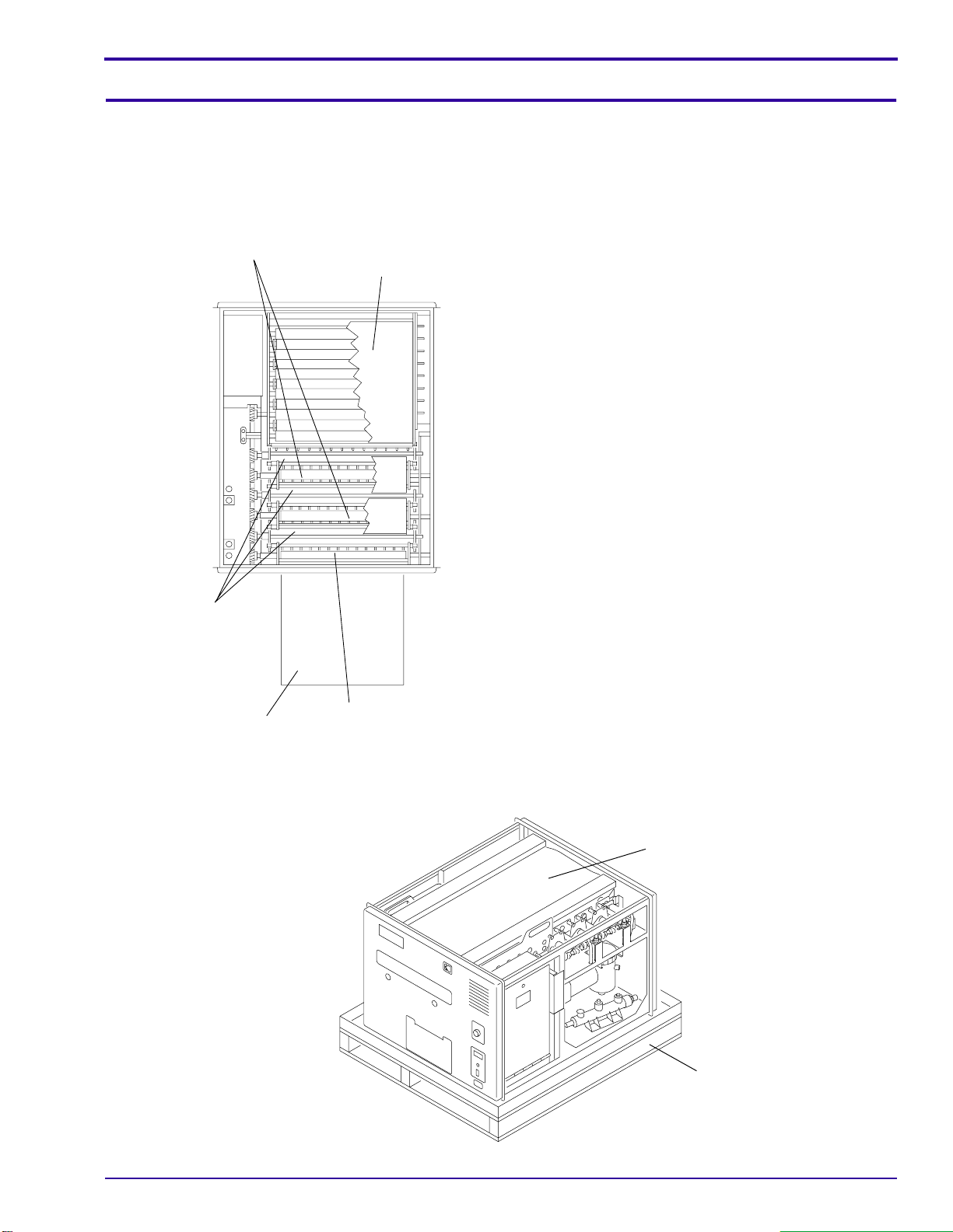
Section 2: Unpacking the PROCESSOR
[1] Remove the PACKING CARTON.
[2] Remove and keep the bags of parts, loose parts,
[3] During the unpacking, check the parts with the
CROSSOVER
ASSEMBLY (2)
DRYER
ASSEMBLY
[4] Remove:
Unpacking the PROCESSOR
and wrapped parts.
Packing List.
• TOP COVER
• 2 SIDE PANELS
• PACKING MATERIAL
• DETECTOR CROSSOVER ASSEMBLY
• 2 CROSSOVER ASSEMBLIES
• DRYER ASSEMBLY
• 3 RACKS
• installation and operator publications
RACK (3)
FEED SHELF
DETECTOR
CROSSOVER
ASSEMBLY
H112_0066CCA
H112_0066CC
PACKING MATERIAL
SHIPPING
BASE
H112_0186BCA
H112_0186BA
981900 – September 1996 5
Page 6
INSTALLATION INSTRUCTIONS
COVER
DRYER ASSEMBLY
H112_0064BCB
H112_0064BA
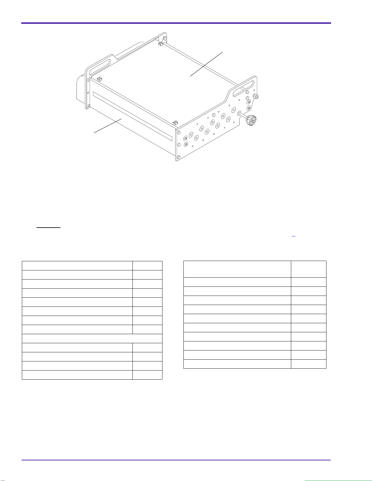
[5] From the DRYER ASSEMBLY, remove the:
• top and bottom COVERS
• PACKING MATERIAL
[6] Install the top and bottom COVERS on the DRYER ASSEMBLY.
[7] Carefully remove the PACKING MATERIAL from the TANKS.
[8] Before you start the PROCESSOR installation, check that you have all the parts listed on Page 6.
[9] Remove dust from the TANKS, the RACKS, the CROSSOVER ASSEMBLIES, and the DRYER SECTION by
rinsing with water. Wipe dry with a soft, clean cloth.
Packed In Top of Packing Carton Quantity
Bin - Receiving 1
Deflector - Bin 1
Feed Shelf Assembly 1
Gasket - Light Lock 1
Weir - Developer, red 1
Weir - Fixer, blue 1
Weir - Wash, beige 1
Wrapped in Paper Quantity
Cover - Evaporation 2
Guard - Splash 1
Tray - Drip 1
Packed In or Is Already On the
Processor Quantity
Cover Assembly 1
Side Panel Assembly 2
Detector Crossover Assembly 1
Fixer/Wash Crossover Assembly 1
Developer/Fixer Crossover Assembly 1
Developer Rack Assembly 1
Fixer Rack Assembly 1
Wash Rack Assembly 1
Dryer Rack Assembly 1
Installation and Operator Publications 2
6 September 1996 – 981900
Page 7

Unpacking the PROCESSOR
Prepack Plastic Bag for an M35A-M
Processor Quantity
Bolt - Hook 2
Cartridge - Filter 1
Clamp - Hose, large 2
Clamp - Hose, small 6
Elbow - Exhaust 1
Elbow - Hose 1
Fastener - Bin 2
Guide - Film, right 1
Nut - No. 8-32 3
Nut - No.1⁄4 -20
Plate - Floor 4
Receptacle - Polarized 1
Screw - No. 8-32 x5⁄
Screw - No. 8-32 x3⁄
Screw - No. 10-32 x3⁄
Screw - No. 10-32 x1⁄
16
8
8
2
Sprocket - 19-Tooth, 50 Hz 1
Strainer Assembly 2
Washer - Flat 4
Washer - Hook 2
Washer - Lock, No. 8 3
Washer - Lock, No. 10 6
Washer - No. 8 3
Washer - No. 10 6
Prepack Plastic Bag for an M35-M
Processor Quantity
Bolt - Hook 2
Bracket - Strain Relief, 220 volt only 1
Cartridge - Filter 1
Clamp - Hose, large 3
Clamp - Hose, small 6
Elbow - Hose 1
Fastener - Bin 2
Guide - Film, right 1
Nut - No. 8-32 3
4
Nut - No.1⁄4 -20
4
Plate - Floor 4
Relief - Strain, 220 volt only 1
1
3
2
4
Screw - No. 8-32 x3⁄
Screw - No. 10-32 x3⁄
Screw - No. 10-32 x1⁄
8
8
2
Sprocket - 19-Tooth, 50 Hz 1
3
3
4
Strainer Assembly 2
Strip - Data 1
Tie - Wire 2
Washer - Flat 4
Washer - Hook 2
Washer - Lock, No. 8 3
Washer - Lock, No. 10 7
Washer - No. 8 3
Washer - No. 10 7
981900 – September 1996 7
Page 8
INSTALLATION INSTRUCTIONS
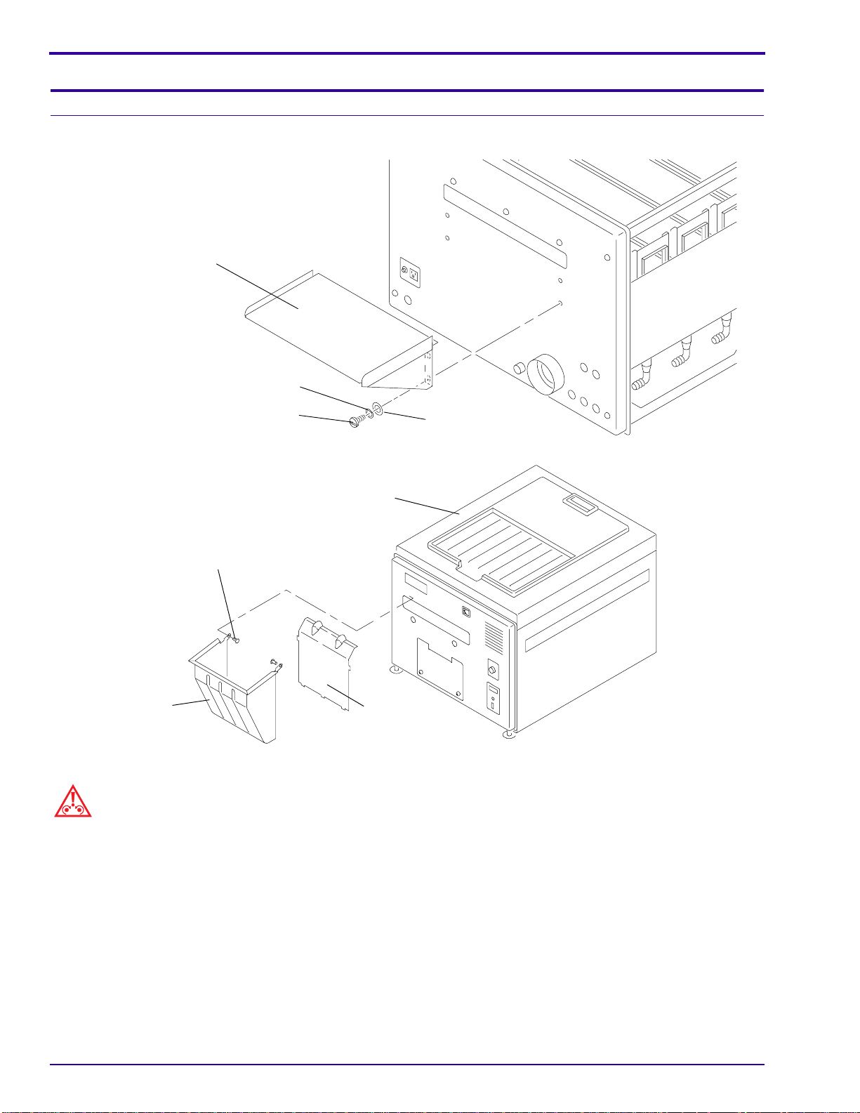
Section 3: Preparing the PROCESSOR for Installation
Installing the FEED SHELF
FEED SHELF
LOCK WASHER (4)
SCREW (4)
BIN FASTENER (2)
RECEIVING
BIN
Caution
Do not overtighten the SCREWS.
[1] Install the:
• FEED SHELF
• 4 WASHERS - No. 10
• 4 LOCK WASHERS - No. 10
TOP COVER
DEFLECTOR
WASHER (4)
H112_0193BCA
H112_0193BA
H112_0174BCA
H112_0174BC
• 4 SCREWS - No. 10-32 x1⁄
2
[2] Install the DEFLECTOR in the RECEIVING BIN.
[3] Install the RECEIVING BIN on the PROCESSOR using the 2 BIN FASTENERS.
8 September 1996 – 981900
Page 9
Preparing the PROCESSOR for Installation
Note
If you are using a LIGHTTIGHT FEED TRAY, you cannot feed 2 sheets of 18 x 24 cm film side-by-side.
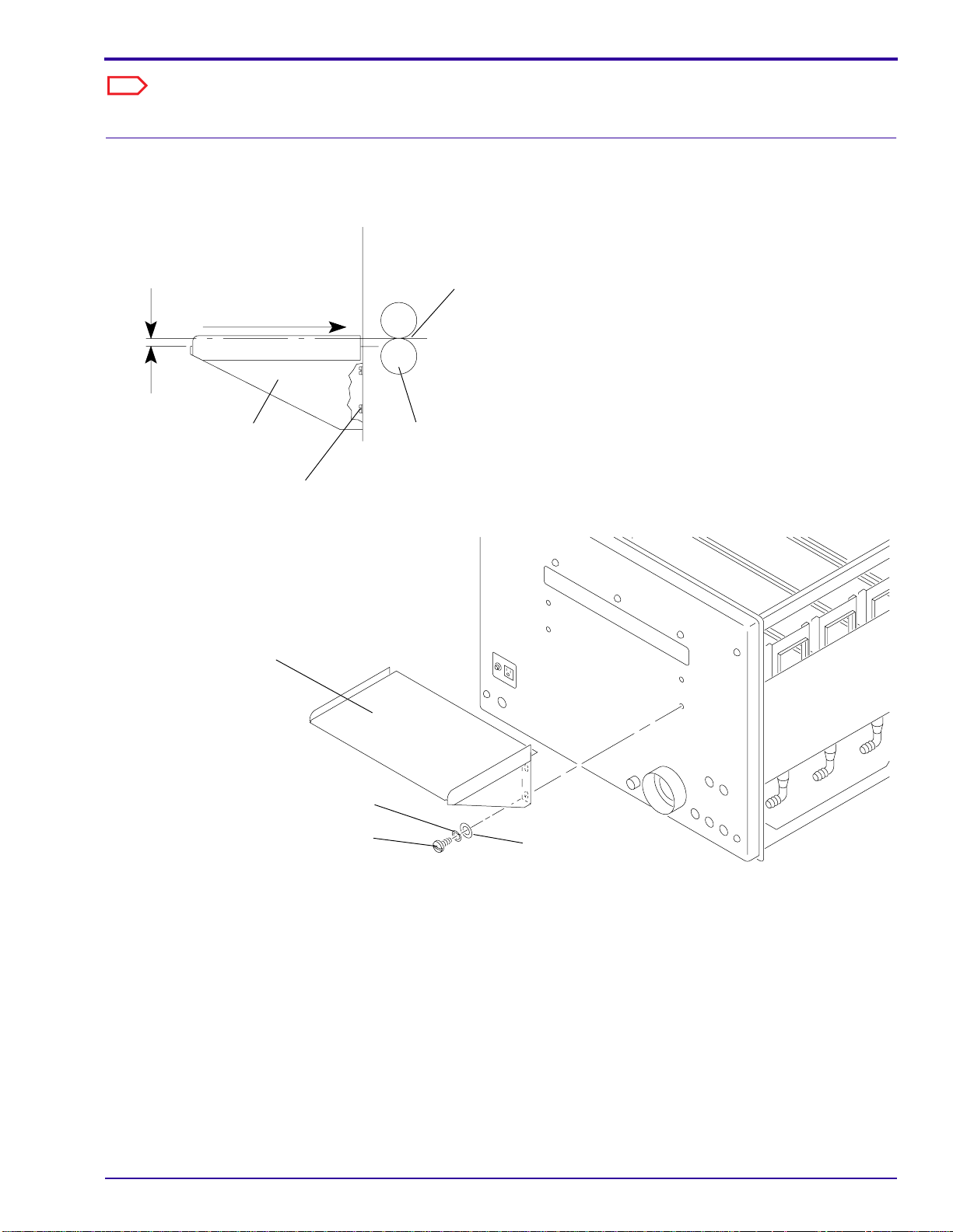
Adjusting the FEED SHELF
[1] Adjust the height of the FEED SHELF to
approximately1.5 mm (0.06 or 1/16in.)belowthe
NIP of theDETECTORCROSSOVER ROLLERS.
1.5 mm
(0.06 in.)
film entry path
FEED
SHELF
SCREW (4)
NIP
DETECTOR
CROSSOVER
ROLLERS
H112_0090ACB
H112_0090AA
(a) Loosen the 4 SCREWS.
(b) Adjust the FEED SHELF for the correct
height by moving the FEED SHELF up or
down.
(c) Inserta sheet of 35 x43cmfilm into the NIP
of the DETECTOR CROSSOVER
ROLLERS.
[2] Use the edges of the film to align the FEED
SHELF with the DETECTOR CROSSOVER
ROLLERS for squareness.
[3] Tighten the 4 SCREWS.
FEED SHELF
LOCK WASHER (4)
SCREW (4)
WASHER (4)
H112_0193BCA
H112_0193BA
981900 – September 1996 9
Page 10
INSTALLATION INSTRUCTIONS
Installing the DEVELOPER RACK and the DETECTOR CROSSOVER AY
WEIR (3)
SCREW (2)
RACK
SUPPORT
DEVELOPER RACK
DETECTOR
CROSSOVER
ASSEMBLY
H112_0150DCA
H112_0150DA
[1] Install the 3 WEIRS.
[2] Install the DEVELOPER RACK.
[3] Loosen the 2 SCREWS and pull the RACK SUPPORT to the nondrive side of the PROCESSOR.
[4] Check the clearance by removing the WEIRS and the DEVELOPER RACK.
[5] If necessary, move the RACK SUPPORT.
[6] Tighten the 2 SCREWS on the RACK SUPPORT.
[7] Install:
• DEVELOPER RACK
• WEIRS
• DETECTOR CROSSOVER ASSEMBLY
10 September 1996 – 981900
Page 11
Section 4: Installing the PROCESSOR
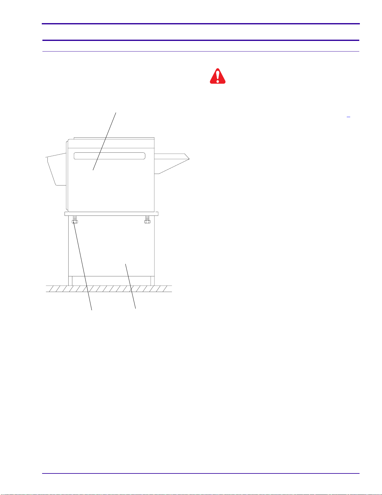
Installing the PROCESSOR onto a Flat Surface
PROCESSOR
Installing the PROCESSOR
Warning
ThePROCESSORweighs90kg(200 lb). Usequalified
personnel to install this PROCESSOR.
[1] Remove the PROCESSOR from the SHIPPING
BASE. See the figure at the bottom of Page 5.
[2] Remove the 4 LEVELING SCREWS from the
PROCESSOR.
[3] Install the PROCESSOR on a stable, flat surface
or on a
STAND, CAT No. 808 1176.
[4] Install the LEVELING SCREWS through the
MOUNTING STAND or the stable, flat surface.
Kodak
M35/M43
X-Omat
MOUNTING
LEVELING
SCREW
(4)
981900 – September 1996 11
MOUNTING
STAND
H112_0148CCA
H112_0148CA
Page 12
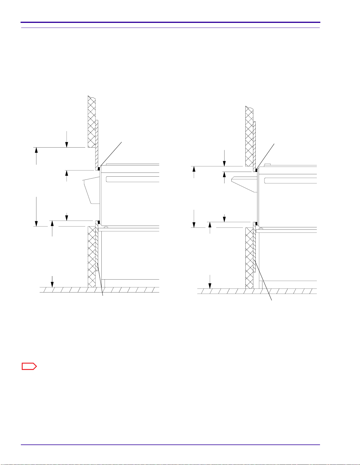
INSTALLATION INSTRUCTIONS
H112_0129CA
Dark Room
5 cm
(2 in.)
Offset
56 cm
(22 in.)
Opening
in wall
46 cm
(18 in.)
Plywood
opening
Leave flexibility
in this dimension
to allow for
leveling
of processor
H112_0129CCA
GASKET
LIGHT LOCK
cover wall opening
frame, large enough to
20 mm (0.75 in.) plywood
Installing the PROCESSOR Through a Wall
Wall Installation with the RECEIVING BIN through
the Wall
Dark Room
20 cm
(8 in.)
Offset
LIGHT LOCK
GASKET
71 cm
(28 in.)
Opening
in wall
46 cm
(18 in.)
Plywood
opening
Wall Installation with the FEED SHELF through the
Wall
Leave flexibility
in this dimension
to allow for
leveling
of processor
Note
The PROCESSOR may be installed with either the FEED SHELF or the RECEIVING BIN through the wall.
20 mm (0.75 in.)
plywood frame,
large enough to
cover wall opening
H112_0128CCA
H112_0128CA
12 September 1996 – 981900
Page 13

20 mm
(0.75 in.)
plywood
frame to
cover wall
opening
46 cm
(18 in.)
Installing the PROCESSOR
LIGHT LOCK GASKET
around opening
and attached to
plywood frame
61 cm (24 in.)
HOOK BOLT (2)
LEVELING
SCREW (4)
HOOK
FLOOR PLATE (4)
WASHER (2)
HOOK
NUT (4)
48.7 cm
(19.18 in.)
2.5 cm (1.0 in.)
1.4 cm (.56 in.)
Warning
• The PROCESSOR weighs 90 kg (200 lb). Use qualified personnel to install this PROCESSOR.
• Do not pull the LIGHT LOCK GASKET too tightly.
H112_0130DCA
H112_0130DA
[1] Install the LIGHT LOCK GASKET to the PLYWOOD FRAME. Do not stretch the LIGHT LOCK GASKET.
981900 – September 1996 13
Page 14

INSTALLATION INSTRUCTIONS
Leveling the PROCESSOR
FLOOR PLATE (4)
LEVELING
SCREW
(4)
2.5 cm
(1.00 in.)
H112_0133ACA
H112_0133AA
[1] Move the PROCESSOR into position.
[2] Install the 4 FLOOR PLATES under the
LEVELING SCREWS or under the MOUNTING
STAND.
Note
If using an M35/M43 MOUNTING STAND, bolt the
PROCESSORto the MOUNTING STAND and level the
MOUNTING STAND.
[3] Install the other RACKS and the CROSSOVER
ASSEMBLIES.
[4] Place the LEVEL on the CROSSOVER
ASSEMBLIES, not on the walls of the
PROCESSOR.
[5] Level the PROCESSOR side-to-side and then
end-to-end.
[6] Install the 2 HOOK BOLTS around the front 2
LEVELING SCREWS and through the wall. See
the figure on Page 13.
[7] Install the 4 HOOK NUTS and the 2 HOOK
WASHERS on the 2 HOOK BOLTS.
LEVEL
H112_0126BCA
H112_0126BA
14 September 1996 – 981900
Page 15

Installing SEISMIC BRACKETS
Installing the PROCESSOR
LEVELING
SCREW
(4)
FLOOR
PLATE
(4)
SEISMIC BRACKET KIT
H112_0189DCA
H112_0189DA
Important
Local building codes may require that SEISMIC BRACKETS be used.
[1] Install SEISMIC BRACKETS to the PROCESSOR or to the MOUNTING STAND if required by local codes. A
Seismic Bracket Kit, Part No. 261413, is available.
981900 – September 1996 15
Page 16

INSTALLATION INSTRUCTIONS
16 September 1996 – 981900
Page 17

Connecting the Plumbing
Section 5: Connecting the Plumbing
Warning
• Drains must be made of chemically resistant, non-corrosive material. Use PVC or the equivalent.
• The drain must have a minimum diameter of 7.6 cm (3 in.) and be free of obstruction.
• Drain service must comply with all local codes.
• Donot makea solid connection to the FLOOR DRAIN. Use anopen FLOOR DRAINwith a minimum clearance
of 2.5 cm (1 in.) between the tubing from the PROCESSOR and the FLOOR DRAIN.
[1] Check that the developer and fixer WEIRS are installed correctly.
[2] Use1⁄2 -in. (1.27 cm) ID tubing, Part No. 760476, to connect the developer, fixer, and wash DRAINS to the
FLOOR DRAIN. See the figure on Page 18. Order the tubing by the foot.
[3] Connect the incoming water supply to the WATER INLET of the PROCESSOR.
WEIRS
wash
WATER INLET
wash
fixer
DRAIN (3)
981900 – September 1996 17
developer
fixer
developer
H112_0160DCB
H112_0160DA
Page 18

INSTALLATION INSTRUCTIONS
Section 6: Connecting the REPLENISHMENT TANKS to the
REPLENISHMENT PUMPS and the SILVER RECOVERY UNIT
Caution
• Do not allow water in the tubing from the REPLENISHMENT TANKS.
• The highest solution level in the REPLENISHMENT TANKS must be below the solution level in the processing
TANKS.
• Maximum solution level is 97 cm (38 in.) with the PROCESSOR installed on an M35/M43 MOUNTING STAND.
[1] Check that the connections in the tubing are tight.
[2] Install the 2 STRAINERS in the tubing between the REPLENISHMENT PUMP and the REPLENISHMENT
TANKS. Use the3⁄8 -in. (9.5 mm) TUBING supplied.
[3] Connect the TUBING from the PUMPS to the processing TANKS.
[4] Check that the REPLENISHMENT TANKS are connected to the correct processing TANKS.
OUT
IN
REPLENISHMENT TANKS
STRAINERS
[5] Connect the SILVER RECOVERY UNIT to the
fixer DRAIN with1⁄2 -in. (1.27 cm) ID tubing.
FLOOR DRAIN
H104_0026BCB
SILVER RECOVERY UNIT
H112_0118AC
18 September 1996 – 981900
Page 19

Section 7: Environmental Requirements
Connecting the EXHAUST HOSE
The building ventilation system must draw air to the
outside of the building, so that no air is reused.
EXHAUST
DUCT
EXHAUST
HOSE
5 cm (2 in.)
maximum
Clearance for
Exhaust Duct
H104_0005ACA
H104_0005AA
[1] Connect a 7.6 cm (3 in.) EXHAUST HOSE, not
[2] Connect the EXHAUST HOSE to the EXHAUST
[3] Leave a 5 cm (2 in.) air gap between the
Environmental Requirements
Caution
supplied, to the EXHAUST ADAPTER.
DUCT from the building ventilation system.
EXHAUST HOSE and the EXHAUST DUCT.
Important
• Ifthe venting is not correct, fumes will corrode equipment andcause artifacts. Donot install the PROCESSOR
or accessories if the venting is not correct.
• The building ventilation system must draw air to the outside of the building, so that no air is reused.
• The AIR FLOW is correct when the fumes are flowing out of the PROCESSOR through the EXHAUST HOSE.
Before installing the PROCESSOR, or at the next service call, do the following to check that the AIR FLOW is
correct.
EXHAUST ADAPTER
981900 – September 1996 19
H112_0166BCA
H112_0166BA
Page 20

INSTALLATION INSTRUCTIONS
Checking the Ventilation
Important
• If the venting is not correct, fumes will corrode the equipment. Do not install the PROCESSOR or accessories
if the venting is not correct. Check local codes for venting requirements.
• Theair flow is correct whenthe fumes are flowing fromthe PROCESSOR through the EXHAUSTHOSE. Before
installing the PROCESSOR, orwhen checking thestatic pressurelater, do thefollowing procedureto checkthat
the air flow is correct.
AIR FLOW
30 cm
(12 in.)
AIR METER
EXHAUST HOSE
RUBBER HOSE or
MODIFIED J TUBE
TAPE (3 places)
HOSE SUPPORT
CENTER CONNECTOR
H048_0118BCA
H048_0118BA
Use an AIR METER TL-2431, to check that the venting is correct.
[1] If the PROCESSOR is installed, de-energize the PROCESSOR.
[2] Disconnect the EXHAUST HOSE from the EXHAUST ADAPTER on the PROCESSOR.
[3] Place the RUBBER HOSE on the CENTER CONNECTOR of the AIR METER.
[4] If a replenishment J TUBE, Part No. 592380, is available, do the following. If not, advance to Step 5.
(a) Cut off and discard the curved portion of the replenishment J TUBE.
(b) Install the tapered end of the replenishment J TUBE into the RUBBER HOSE.
(c) Advance to Step 7.
[5] Ifa replenishment J TUBE is not available, align a HOSE SUPPORT, such as a straightened coat hanger, next
to the RUBBER HOSE. The ends of the HOSE SUPPORT and the RUBBER HOSE must be together.
[6] Place tape around the HOSE SUPPORT and the RUBBER HOSE at 3 points. See the figure.
Important
The tape should not inhibit the air flow through the RUBBER HOSE.
[7] Insert the replenishment J TUBE or the RUBBER HOSE into the EXHAUST HOSE until the end is 30 cm
(12 in.) from the end of the EXHAUST HOSE.
20 September 1996 – 981900
Page 21

Measuring the Static Pressure
Negative Static Pressure, Water Head
Duct Diameter MIN MAX
76 mm (3 in.) 0.76 mm (0.03 in.) 1.02 mm (0.04 in.)
102 mm (4 in.) 0.25 mm (0.01 in.) 0.51 mm (0.02 in.)
5 cm (2 in.)
Exhaust
Duct
Exhaust
Hose
maximum
Clearance for
Exhaust Duct
Environmental Requirements
Important
The RUBBER HOSE or J TUBE must be in the center
of the EXHAUST DUCT.
[8] Hold the AIR METER vertical, and record the
average of several readings.
[9] Compare the average reading with the table:
[10] Adjust one of the following to obtain the required
reading:
(a) thedamper(orfan) in the buildingventilation
system or
(b) theclearance betweenthe EXHAUSTDUCT
andthe EXHAUSTHOSE to 5cm(2 in.); see
the figure.
[11] Ifthe air flowreadingis still not correct,contactthe
sales representative and the customer to correct
the venting.
[12] When the air flow reading is the same as the
measurements in the table, connect all the hoses.
[13] Ifthe PROCESSOR has been installed, install the
COVERS and PANELS on the PROCESSOR.
H104_0005ACB
H104_0005AA
Important
• Inform the customer that all COVERS and PANELS must be installed while the PROCESSOR is energized.
• The darkroom should have 10 room air exchanges per hour.
• If the PROCESSOR is installed through the darkroom wall, it is most important that the air pressure in the
darkroom is greater than the air pressure of the area surrounding the darkroom.
[14] Do the following to check the air flow at the FEED SHELF:
(a) If the PROCESSOR is installed, de-energize the PROCESSOR.
(b) Hold a piece of tissue paper in front of the FEED SHELF.
Note
The air flow should be toward the PROCESSOR.
(c) If the tissue paper moves away from the PROCESSOR, call Customer Service for Health Imaging,
Monday through Friday from 8:00 a.m. to 5:00 p.m. (Rochester, New York, time) at (800) 336-4722.
981900 – September 1996 21
Page 22

INSTALLATION INSTRUCTIONS
Section8: ConnectingtheMainPowerforanM35A-MPROCESSOR,120
Volts Only
TOP COVER
MAIN POWER SWITCH
H112_0043ACE
H112_0043AC
Connecting the Main Power to an M35A-M PROCESSOR
Warning
• Dangerous voltage.
• Possible damage from electrostatic discharge.
[1] Check and use the Local Electrical Codes.
[2] Consult with the customer about installing the
POLARIZED RECEPTACLE.
[3] Turn off the power to the wall outlet where the
POLARIZED RECEPTACLE will be installed.
[4] Install, or have the customer install, the
POLARIZED RECEPTACLE.
Note
The COVER PLATE is not supplied.
[5] Move the MAIN POWER SWITCH on the
PROCESSOR to the “OFF” position.
[6] Plug the POWER CORD into the POLARIZED
RECEPTACLE.
POLARIZED
RECEPTACLE,
M35A-M Processor
only
POWER
CORD
H112_0122BCC
H112_0122BA
22 September 1996 – 981900
Page 23

Connecting the POWER CORD on an M35-M PROCESSOR, 220 Volts Only
Section9: Connecting thePOWERCORDonanM35-MPROCESSOR,
220 Volts Only
Warning
• Dangerous voltage.
• Possible damage from electrostatic discharge.
[1] Check and use the Local Electrical Codes.
[2] Disconnect the main power at the wall.
[3] Move the MAIN POWER SWITCH to the “OFF” position.
[4] Remove the TOP COVER and the drive SIDE PANEL, not shown.
[5] Open the DOOR to the ELECTRICAL BOX.
[6] Move wire No. 8A to the correct terminal on TB5. See the figure on Page 24.
[7] Move JUMPER 8:
Volts Position of Jumper 8
200 or 208 TB5-2
220 TB5-3
240 TB5-4
[8] Apply the correct DATA STRIP inside the ELECTRICAL BOX DOOR to indicate the correct supply voltage.
[9] Install the STRAIN RELIEF BRACKET inside the PROCESSOR. See the figure below.
[10] Feed the CABLE through the FRONT PANEL.
[11] Insert the CABLE through the STRAIN RELIEF.
[12] Install the STRAIN RELIEF to the STRAIN RELIEF BRACKET with the NUT.
[13] Feed the CABLE into the ELECTRICAL BOX.
[14] Connect the incoming wires to L1, L2, and N of TB1. See the connection charts on the circuit diagrams that
start on Page 25.
[15] Connect the ground wire to the GROUND LUG, not shown.
[16] Install the 2 WIRE TIES to the CABLE and the STRAIN RELIEF.
[17] Close the DOOR to the ELECTRICAL BOX, and install the drive SIDE PANEL and the TOP COVER.
FRONT PANEL
CABLE
STRAIN RELIEF
NUT
ELECTRICAL BOX
981900 – September 1996 23
STRAIN
RELIEF
BRACKET
H112_0173BCA
H112_0173BA
Page 24

INSTALLATION INSTRUCTIONS
Connecting the 220 Volt POWER CORD
TB5
TB1
DATA
STRIP
DOOR
ELECTRICAL
BOX
H112_0187ECD
H112_0187EC
24 September 1996 – 981900
Page 25

Section 10: Circuit Diagrams
Processor Diagram See Page
M35-M Circuit Diagram, Sheet 1 of 2 25
M35-M Circuit Diagram, Sheet 2 of 2 25
M35A-M Circuit Diagram 25
Circuit Diagrams
Page 26 - Circuit Diagram, M35-M Processor, Sheet 1 of 2
Circuit Diagram, M35-M Processor, Sheet 2 of 2 - Page 27
Page 28 - Circuit Diagram, M35A-M Processor
981900 – September 1996 25
Page 26

INSTALLATION INSTRUCTIONS
Section 11: Preparing the PROCESSOR for Use
Checking the Tubing CLAMPS, TANKS, and RACKS
[1] Tighten and check all CLAMPS.
Caution
Check all CLAMPS 2 - 4 weeks after installing any new tubing. Tighten the CLAMPS if necessary. Although a
CLAMP may be tight when tubing is installed, temperature changes or shrinkage of the plastic tubingwill cause the
CLAMP to loosen.
[2] Check that the 3 WEIRS are installed and fully seated:
red in the developer TANK
blue in the fixer TANK
beige in the wash TANK
[3] Fill the 3 TANKS with water.
[4] Operate the PROCESSOR for a few minutes, and check for leakage.
[5] Drain the PROCESSOR completely.
TANK (3)
WEIR (3)
FILL TUBE
H112_0154DCB
H112_0154DA
26 September 1996 – 981900
Page 27

[6] Rinse the DEVELOPER, FIXER, and WASH RACKS with warm water.
H112_0117AC
GUARD
SPLASH
H112_0117ACA
[7] Rotate the ROLLERS manually to check that the ROLLERS rotate fully.
[8] Check that all the moving parts engage correctly.
[9] Wait to install the RACKS until Page 32.
Filling the TANKS
[1] Soakthe DEVELOPERFILTER for 30 secondsin
warm water.
[2] Insert the DEVELOPER FILTER into the FILTER
HOUSING.
[3] Check that the O-RING is seated correctly, or
leakage may occur.
[4] Tighten the CAP and install the FILTER
HOUSING in the PROCESSOR.
[5] Check that the tubing is not kinked.
Caution
To avoid contamination of the solutions:
• Rinsethe mixingand fillingequipment beforeeach
CAP
O-RING
use.
• Mix the developer first, then the fixer.
• Fill the FIXER TANK first.
• Wash the mixing equipment thoroughly between
solutions.
[6] Install the SPLASH GUARD between the
DEVELOPER TANK and the FIXER TANK.
Preparing the PROCESSOR for Use
DEVELOPER
FILTER
FILTER
HOUSING
H112_0169CCA
H112_0169CA
981900 – September 1996 27
Page 28

INSTALLATION INSTRUCTIONS
WEIRS
FIXER
TANK
H112_0014ACC
H112_0014AC
WASH
TANK
DEVELOPER
TANK
FILL
LINES
[7] To fill the FIXER TANK, add FIXER
REPLENISHER until the solution is at the higher
FILL LINE on the blue WEIR.
[8] Remove and rinse the SPLASH GUARD.
[9] Install the SPLASH GUARD over the FIXER
TANK.
[10] To fill the DEVELOPER TANK:
(a) Fill the DEVELOPER TANK half full of
DEVELOPER REPLENISHER from the
REPLENISHMENT TANK.
(b) Add190 mL(6.5 fl oz) of
KodakRPX-Omat
DEVELOPER STARTER.
(c) Fill the DEVELOPER TANK to the higher
FILL LINE on the red WEIR with
DEVELOPER REPLENISHER.
[11] Remove the SPLASH GUARD and rinse it
thoroughly.
[12] Allow the developer to reach the operating
temperature before processing any film.
Removing the REPLENISHMENT PUMP TIMER, for Very Low Volume Use Only
Important
The PROCESSOR is shipped with the
REPLENISHMENT PUMP TIMER installed.
[1] Skip this procedure if processing less than 30
sheets of film per 8 hours in this PROCESSOR.
Advance to Page 29.
[2] Remove the drive SIDE PANEL.
[3] Open the ELECTRICAL BOX by loosening the
SCREW.
[4] Remove the REPLENISHMENT PUMP TIMER.
[5] Close the ELECTRICAL BOX.
H112_0042ACC
H112_0042AC
SIDE
PANEL
ELECTRICAL
BOX
28 September 1996 – 981900
Page 29

REPLENISHMENT
PUMP TIMER
Preparing the PROCESSOR for Use
SCREW
Checking the Replenishment Flow Rates
METAL
LATCH
H112_0114ACA
H112_0114AC
DEVELOPER TUBING
QUICK
DISCONNECT
GRADUATED
CYLINDER
FIXER TUBING
H112_0041BCC
H112_0041BC
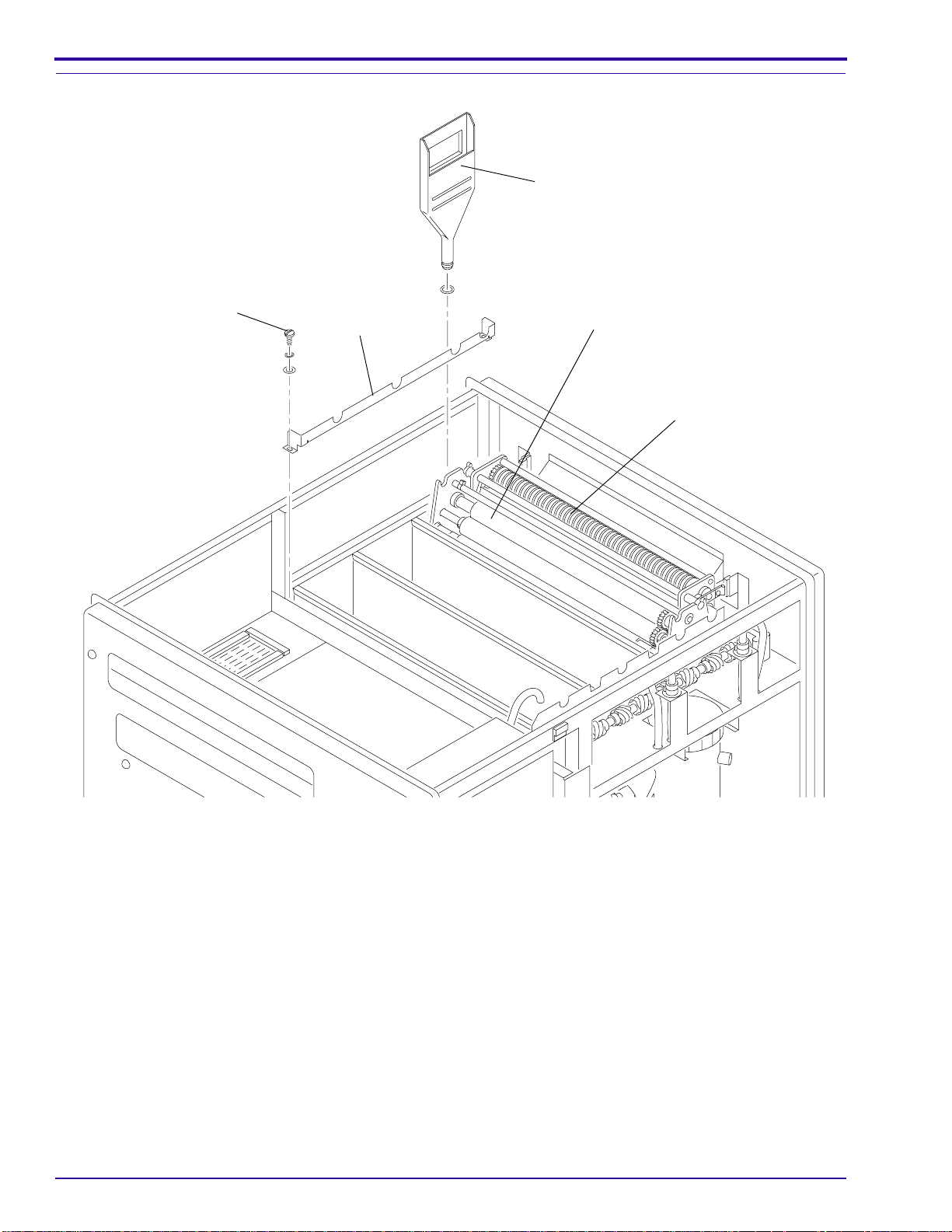
[1] Remove the TOP COVER if installed.
[2] Lift the top ROLLER of the DETECTOR
CROSSOVER ASSEMBLY.
[3] Check that the replenisher solutions flow freely
through the TUBING along the drive side of the
PROCESSOR.
[4] Press the METAL LATCH on the red QUICK
DISCONNECT to disconnect the developer
TUBING.
[5] Pull the TUBING slightly by rotating the TUBING
over the edge of the frame.
[6] Insert the TUBING into a GRADUATED
CYLINDER.
[7] Lift the top ROLLER of the DETECTOR
CROSSOVER ASSEMBLY for the correct time.
See the table on the next page.
Note
The REPLENISHMENT PUMP will operate 3 seconds
after you release the ROLLER.
[8] Check that the amount of developer in the
GRADUATED CYLINDER is the same as in the
table.
[9] If necessary, adjust the REPLENISHMENT
PUMP. See Page 31.
[10] If necessary, do Steps 7 - 9 again.
[11] Connect the QUICK DISCONNECT.
[12] Dothis procedure again with the fixer TUBING to
check the flow rate of the fixer.
981900 – September 1996 29
Page 30

INSTALLATION INSTRUCTIONS
Use
Film Size Processed
Only 35 x 35 cm
(14 x 14 in.) film
Average size film
intermix
Only 35 x 43 cm
(14 x 17 in.) film
Film Size Processed
Only 18 x 24 cm
Kodak Min-R
Only 18 x 24 cm
Kodak Min-R
Only 18 x 24 cm
Kodak Min-R
Only 18 x 24 cm
Kodak Min-R
Film
E Film
M Film
H Film
2000
Condition
High
Medium
Low
High
Medium
Low
High
Medium
Low
Use
Condition
High
Medium
Low
High
Medium
Low
High
Medium
Low
High
Medium
Low
Average Amount of
Film per 8 Hours of
Processor Operation
90 sheets or more
31 - 89 sheets
30 sheets or less
115 sheets or more
41 - 114 sheets
40 sheets or less
75 sheets or more
26 - 74 sheets
25 sheets or less
Average Amount of
Film per 8 Hours of
Processor Operation
150 sheets or more
60 - 149 sheets
59 sheets or less
150 sheets or more
60 - 149 sheets
59 sheets or less
150 sheets or more
60 - 149 sheets
59 sheets or less
150 sheets or more
60 - 149 sheets
59 sheets or less
Replenishment Flow Rate
mL per 35 cm(14 in.)
28 sec
of Film Travel
Developer Fixer
50 70
65 85
80 100
50 70
65 85
80 100
- - 60 85
Replenishment Flow Rate
mL per 24 cm
26 sec
of Film Travel in
Standard Mode
Developer Fixer
- - 20 30
30 30
30 35
35 40
50 30
50 35
50 40
20 30
20 35
20 40
mL per 43 cm (17 in.)
Developer Fixer
of Film Travel in
Extended Mode
Developer Fixer
34 sec
of Film Travel
- -
- -
80 100
100 120
mL per 24 cm
36 sec
27 35
35 40
- -
- -
- -
Note
•
Kodak
RP
X-Omat
• Replenishmentrates are based on one sheet of 18 x 24 cm film. If feeding two sheets, double the replenishment
rates.
• For best results, feed film consistently.
• Slight sensitometric changes will occur as subsequent films are processed through a freshly started process.
This is known as “seasoning” and is normal with any photographic process. Process control targets may have
to be adjusted slightly to compensate.
• For 30 sheets of film or less per day, flooded replenishment is recommended.
• Film travel time includes feed time plus an approximate 3-second delay.
30 September 1996 – 981900
Chemicals are recommended.
Page 31

Adjusting the REPLENISHMENT PUMP
Preparing the PROCESSOR for Use
BRACKET
HOLE
[2] Loosen the 2 SCREWS and remove the PUMP
COVER.
[3] Actuatethe DETECTORSWITCHbyliftingthetop
ROLLER of the DETECTOR CROSSOVER
ASSEMBLY until the ADJUSTMENT SCREW is
visible through the hole in the BRACKET.
[4] Loosen the SETSCREW.
Caution
Do not adjust the LOCKNUT on the other end of the
ADJUSTMENT SCREW.
[1] Remove the TOP COVER.
PUMP
COVER
SCREW (2)
H112_0005ACB
H112_0005AC
[7] Check theflowratesand, ifnecessary,do Steps 2 - 6 again. See the table on Page 30 forvarious replenishment
rates.
[8] Install the TOP COVER and the PUMP COVER.
[9] Feed a sheet of film into the PROCESSOR to check that the REPLENISHMENT PUMPS operate correctly. If
necessary, see the adjustment procedure for the DETECTOR SWITCHES in the Service Manual, Part No.
981901.
[5] Rotate the ADJUSTMENT SCREW to adjust the
flow rate.
clockwise
counterclockwise
increases the flow rate
decreases the flow rate
[6] Tighten the SETSCREW.
SETSCREW
Do not
adjust!
LOCKNUT
H112_0030BCB
H112_0030BC
ADJUSTMENT
SCREW
REPLENISHMENT PUMP
BRACKET
HOLE
ADJUSTMENT SCREW
DECREASE INCREASE
OUTPUT
981900 – September 1996 31
Page 32

INSTALLATION INSTRUCTIONS
H112_0015AC
DRIP TRAY
SPLASH GUARD
H112_0015ACA
Installing the RACKS
DEVELOPER/FIXER
CROSSOVER ASSEMBLY
FIXER/WASH
CROSSOVER
ASSEMBLY
FIXER
WASH
RACK
DRYER
ASSEMBLY
RACK
DETECTOR
CROSSOVER
ASSEMBLY
DEVELOPER
RACK
Caution
Use the DRIP TRAY and SPLASH GUARD when you
install or remove the RACKS. Lower the RACKS
slowly.
[1] Install the RACKS in the correct TANKS. Seat
them firmly.
H112_0171CCA
H112_0171CC
Note
The WASHER on the top of the drive side of the
DEVELOPER RACK has a “D” on it. The one on the
FIXER RACK has an “F”. The RACKS may also have
red, blue, and white wire ties for easy identification.
red DEVELOPER RACK
blue FIXER RACK
white WASH RACK
[2] Install the:
• DEVELOPER/FIXER CROSSOVER
ASSEMBLY
• FIXER/WASH CROSSOVER ASSEMBLY
• DETECTOR CROSSOVER ASSEMBLY
• DRYER ASSEMBLY
• EVAPORATION COVERS, not shown
[3] Check that the gap in the developer RACK
between the the GUIDE SHOES and the
MASTER ROLLER is:
Gap between Shoes and Master Roller
0.020 in.
If necessary, adjust the GUIDE SHOES. See the
procedure in the Service Manual, Publication Part
No. 981901.
32 September 1996 – 981900
Page 33

Checking the Operation of the PROCESSOR
Preparing the PROCESSOR for Use
[1] Turn on the water supply.
[2] Energize the PROCESSOR.
[3] Check that the:
• Developer and fixer have agitation
DRYER
TEMPERATURE
CONTROL
KNOB
TOP COVER
SIDE
PANEL
(2)
• No leakage occurs
• Solutions overflow into the WEIRS
• Water flows into the PROCESSOR
[4] Install the 2 SIDE PANELS and the TOP COVER.
[5] Check the operation of the RUN/STANDBY
SWITCH.
[6] Set the DRYER TEMPERATURE CONTROL
KNOB to the minimum temperature necessary to
provide dry film.
[7] Check that warm air comes out of the exhaust.
RUN/STANDBY
SWITCH
DIGITAL
TEMPERATURE
DISPLAY
H112_0043ACD
H112_0043AC
Note
• The PROCESSOR is now in the run mode.
• If checking both the Standard developer temperature and the Extended developer temperature, check for
Standard Mode first. The correct temperatures are:
Standard: 33.3˚C 0.3˚C (92.0˚F 0.5˚F)
Extended: 35˚C 0.3˚C (95.0˚F 0.5˚F)
[8] Insert a THERMOMETER of known accuracy, such as Part No. 761217, into the nondrive side of the
DEVELOPER TANK between the SIDE PLATE of the DEVELOPER RACK and the RACK SUPPORT.
Insert THERMOMETER
here
Caution
• Possible damage from electrostatic discharge. Use an ESD WRIST STRAP.
• Use the POTENTIOMETER ADJUSTING TOOL TL-1481 to adjust R301 and R302.
H112_0121BCA
H112_0121BA
981900 – September 1996 33
Page 34

INSTALLATION INSTRUCTIONS
[9] If a developer temperature adjustment is necessary, adjust R301 and R302 on the 300 CIRCUIT BOARD.
(a) Remove the drive SIDE PANEL from the PROCESSOR.
(b) Open the ELECTRICAL BOX.
(c) Usethe POTENTIOMETERADJUSTINGTOOLTL-1481 toadjust thedevelopertemperature byrotating
R302 for Standard Mode or R301 for Extended Mode.
clockwise
counterclockwise
increases the temperature
decreases the temperature
(d) Check the developer temperature in the DEVELOPER TANK with a THERMOMETER.
(e) If the developer temperature is not correct, do Steps (c) and (d) again.
Important
• Afterchanging from Extended Modeto Standard Mode,set the DRYERTEMPERATURE CONTROL
KNOB to “0” and remove the TOP COVER for venting. Check that the METER displays the correct
temperature before adjusting R302 or processing film.
•Donot process film until the METER shows that the developer is at the correct temperature.
Adjusting the Developer Temperature on the 300 CIRCUIT BOARD by Rotating R302 for Standard Mode or
R301 for Extended Mode
R302
R301
300 CIRCUIT
BOARD
100 CIRCUIT BOARD
34 September 1996 – 981900
H112_0041BCB
H112_0041BC
Page 35

Preparing the PROCESSOR for Use
Adjusting the Potentiometer on the Developer
Temperature METER
METER
HOLES
H112_0184ACB
H112_0184AC
[10] If the METER does not display the same
temperature as the THERMOMETER, adjust the
METER.
(a) Remove the drive SIDE PANEL.
(b) Open the ELECTRICAL BOX.
(c) Check that CR10 on the 100 CIRCUIT
BOARD is blinking.
(d) AfterCR10 has blinked for 2 minutes,insert
the POTENTIOMETER ADJUSTING TOOL
TL-1481 through the holes in the frame of
the ELECTRICAL BOX.
(e) Rotate TL-1481 to adjust the METER.
clockwise
increases the
temperature display
counterclockwise
decreases the
temperature display
(f) Check the developer temperature with the
THERMOMETER. If the temperature is not
the same as on the METER, adjust the
METER again.
[11] Close the ELECTRICAL BOX.
[12] Install the SIDE PANELS and the TOP COVER.
[13] Check the operation of the DETECTOR
SWITCHES by feeding a sheet of filmthrough the
PROCESSOR to check that the
REPLENISHMENT PUMP is operating.
981900 – September 1996 35
Page 36

INSTALLATION INSTRUCTIONS
Adjusting the Speed of the MAIN DRIVE MOTOR
R202
R201
STD/EXT SWITCH
200 CIRCUIT BOARD
REPLENISHMENT
PUMP TIMER
ELECTRICAL
BOX
H112_0187ECE
H112_0187EC
36 September 1996 – 981900
Page 37

Preparing the PROCESSOR for Use
[1] Determine the speed of the MAIN DRIVE
MOTOR.
(a) Process sheets of 24 cm (10 in.) film in
Extended and Standard Modes.
(b) Record the dry-to-dry processing times.
SIDE
PANEL
The correct time for a 24 cm (10 in.) film is:
Extended: 3 minutes and 23 seconds
Standard: 2 minutes and 15 seconds
ELECTRICAL
BOX
H112_0042ACC
H112_0042AC
[2] If the dry-to-dry processing times are not correct, adjust the speed of the MAIN DRIVE MOTOR.
(a) Remove the TOP COVER and drive SIDE PANEL from the PROCESSOR.
ESD
Possible damage from electrostatic discharge.
(b) Open the ELECTRICAL BOX.
(c) Set the STD/EXT SWITCH to “STD”.
(d) Feed 24 cm (10in.) of film into the PROCESSOR. Measure the time for each 24 cm(10 in.) of film to enter
the PROCESSOR. The correct time is: Standard: 19 seconds
(e) Set the STD/EXT SWITCH to “EXT”.
(f) Feed 24 cm (10in.) of film into the PROCESSOR. Measure the time for each 24 cm(10 in.) of film to enter
the PROCESSOR. The correct time is: Extended: 29 seconds
(g) Ifthe transport time is not correct, adjust R201for theExtended Modeor R202 for the Standard Modeon
the 200 CIRCUIT BOARD. See the figure on Page 36.
Important
It is important to check the speed of both modes, especially if an adjustment is necessary for one mode.
(h) DoSteps (a)-(g) again to check the processing times. Continue the procedure until the processingtimes
are correct.
(i) Close the ELECTRICAL BOX.
[3] Install the SIDE PANEL and the TOP COVER.
981900 – September 1996 37
Page 38

Publication History
Section 12: Publication History
Affected
Print Date Pub. No. ECO No.
Sept 1992 981900 4014-318 All 3133ii_f.txt Original Printing in caps
Sept 1996 981900 4014-432 All ii3133_1_432.doc Revisedto reflect the new sizeFeed Shelf,
Pages File Name Notes
update the replenishment flow rate table,
and add warnings on drain construction.
Converted to FrameBuilder.
ii313301.fm
Printed In USA
Kodak, Min-R,
and
X-Omat
are trademarks.
Health Imaging
EASTMAN KODAK COMPANY ● ROCHESTER, N.Y. 14650
 Loading...