

Page 1

Publication No. 990602
INSTALLATION INSTRUCTIONS
for the
January 1996
Supersedes 990602
August 1993
Kodak X-Omatic
MODELS 4, 4L, and 4SL
IDENTIFICATION CAMERA
© Eastman Kodak Company
Page 2

PLEASE NOTE The information contained herein is based on the experience and knowledge relating to the
subject matter gained by Eastman Kodak Company prior to publication.
No patent license is granted by this information.
Eastman Kodak Company reserves the right to change this information without notice, and
makes no warranty, express or implied, with respect to this information. Kodak shall not be liable
for any loss or damage, including consequential or special damages, resulting from any use of
this information, even if loss or damage is caused by Kodak’s negligence or other fault.
This equipment includes parts and assemblies sensitive to damage from electrostatic
discharge. Use caution to prevent damage during all service procedures.
Table of Contents
Description Page
Electrostatic Discharge . . . . . . . . . . . . . . . . . . . . . . . . . . . . . . . . . . . . . . . . . . . . . . . . . . . 3
Description and Specifications . . . . . . . . . . . . . . . . . . . . . . . . . . . . . . . . . . . . . . . . . . . . . 4
Description . . . . . . . . . . . . . . . . . . . . . . . . . . . . . . . . . . . . . . . . . . . . . . . . . . . . . . . . . 4
Specifications. . . . . . . . . . . . . . . . . . . . . . . . . . . . . . . . . . . . . . . . . . . . . . . . . . . . . . . 4
Space Requirements . . . . . . . . . . . . . . . . . . . . . . . . . . . . . . . . . . . . . . . . . . . . . 4
Environmental Requirements . . . . . . . . . . . . . . . . . . . . . . . . . . . . . . . . . . . . . . 4
Cassettes . . . . . . . . . . . . . . . . . . . . . . . . . . . . . . . . . . . . . . . . . . . . . . . . . . . . . 5
Power Requirements . . . . . . . . . . . . . . . . . . . . . . . . . . . . . . . . . . . . . . . . . . . . . 5
Unpacking the ID CAMERA . . . . . . . . . . . . . . . . . . . . . . . . . . . . . . . . . . . . . . . . . . . . . . . 6
Setting Up the ID CAMERA . . . . . . . . . . . . . . . . . . . . . . . . . . . . . . . . . . . . . . . . . . . . . . . 9
Selecting the Correct Voltage . . . . . . . . . . . . . . . . . . . . . . . . . . . . . . . . . . . . . . 9
Selecting the Date Format . . . . . . . . . . . . . . . . . . . . . . . . . . . . . . . . . . . . . . . . . 11
Selecting the Time Format . . . . . . . . . . . . . . . . . . . . . . . . . . . . . . . . . . . . . . . . 14
Setting the Date and Time . . . . . . . . . . . . . . . . . . . . . . . . . . . . . . . . . . . . . . . . . 17
Clearing the Date and Time . . . . . . . . . . . . . . . . . . . . . . . . . . . . . . . . . . . . . . . 19
Performing the Density Step Test Procedure . . . . . . . . . . . . . . . . . . . . . . . . . . . . . . . . . . 20
Publication History . . . . . . . . . . . . . . . . . . . . . . . . . . . . . . . . . . . . . . . . . . . . . . . . . . . . . . 21
2 January 1996 – 990602
Page 3

Section 1: Electrostatic Discharge
Overview
Electrostatic discharge (ESD) is a primary source of
• product downtime
• lost productivity
• costly repairs
While you cannot feel a static charge of less than 3,500 volts, as few as 30 volts can damage or destroy
essential components in electronic equipment.
Preventive Measures
• Always look for an ESD warning label before doing any procedure involving static-sensitive
components such as CIRCUIT BOARDS. All static-sensitive components are marked with bright
graphic labels, which frequently include instructions. Follow all label instructions.
• Wear a grounding strap whenhandling static-sensitive components. Alwaysmake certain that the
clip remains attached to a properly grounded, unpainted, clean surface.
• Repair static-sensitive components at an ESD-protected work station or use a portable grounding
mat. For help in setting up an ESD-protected work station, contact your Kodak representative
• When you move static-sensitive components from one area to another, insert and transport the
components in ESD-protective packaging.
Electrostatic Discharge
990602 – January 1996 3
Page 4

INSTALLATION INSTRUCTIONS
Section 2: Description and Specifications
Description
The
Kodak X-Omatic
CAMERA), records patient identification data onto x-ray film in lighttight cassettes.
The camera provides:
• Dual lenses for use with C-1 and C-1N windows for MODELS 4 and 4L
• Excellent image quality with high-quality lenses
• Operation in normal room illumination
• The exact time anddate of the exposurerecorded on the film witha variety of customizeddate and time formats
available
• The serial number of the camera is recorded on the film for all models and lens positions except the C-1N lens
position in the MODEL 4L.
• Choice of both anterior-posterior and posterior-anterior imaging
• MODEL 4 records patient data on the upper corner of the film
• MODELS 4L and 4SL record patient data on the lower corner of the film
When you insert a CASSETTE correctly into the SLOT above the BASE, and a patient ID CARD is in either the PA or A-P SLOT, the camera automatically:
[1] Actuates a mechanical ARM to open a WINDOW in the CASSETTE.
[2] Illuminates the LAMP to record the identification data, time, and date on the film.
[3] Closes the WINDOW in the CASSETTE.
This entire operation takes approximately 2 seconds.
IDENTIFICATION CAMERA, MODELS 4, 4L, and 4SL (hereafter referred to as the ID
Specifications
Space Requirements
• The physical characteristics of the camera are:
Height: 32.5 cm (12.80 in.)
Width: 32.4 cm (12.76 in.)
Depth: 43.5 cm (17.13 in.)
Weight: 12 kg (26.5 lb)
• Install the camera on a flat surface, with a minimum overhead clearance of approximately 75 cm (30 in.).
• To be able to insert the largest CASSETTES, provide these clearances:
1 m (3 ft) between the front edge of the camera and the nearest wall
1 m (3 ft) between the right edge of the camera and the nearest wall
Environmental Requirements
The camera operates in the ambient room conditions normally encountered in an x-ray department:
15 to 30˚C (59 to 86˚F)
15 to 76% relative humidity
4 January 1996 – 990602
Page 5

Description and Specifications
Cassettes
The ID CAMERA will operate with the following CASSETTES:
• All sizes of
• All sizes of
• All sizes of
Kodak X-Omatic
Kodaflex
Kodak Min-R
CASSETTES with C-1 windows
2 CASSETTES with C-1N windows
CASSETTES with C-1 windows
Power Requirements
[1] For theMODELS4,4L,and4SL ID CAMERAS: These cameraswill operate correctly at the followingvoltages
and tolerances. The cameras are internally switchable to obtain each of the following voltage ranges.
[2] Do not connect the camera to a power source that serves other equipment.
[3] Small variations in the voltage can cause variations in the density of the film. If necessary, install a voltage
regulator for a constant AC voltage to the camera.
[4] Use a reliable earth ground.
[5] Use the correct FUSE for your current.
Frequency
Model
4, 4L, and 4SL 50 or 60 1.5 220 TUV 1 A
(Hz)
50 or 60 3 100 UL/CSA 3 A
50 or 60 3 120 UL/CSA 3 A
50 or 60 1.5 230 TUV 1 A
50 or 60 1.5 240 TUV 1 A
Maximum
Current (A) V AC 10% Fuse
990602 – January 1996 5
Page 6

INSTALLATION INSTRUCTIONS
Section 3: Unpacking the ID CAMERA
SUPPORT (4)
SUPPORT
(4)
RETAINING
CUSHION
ACCESSORY
BOX
CAMERA
BOX
Caution
Do not turn the shipping carton upside down.
Important
Be careful opening the shipping carton and removing
the packing material. Keep the carton and all packing
materialfor the customer, incase the ID CAMERA must
be returned for service.
[1] Remove the sealing tape from the shipping
carton.
[2] Removethe4 SUPPORTSfrom the topcornersof
the CAMERA BOX.
[3] Open the CAMERA BOX.
[4] Remove the RETAINING CUSHION and the
ACCESSORY BOX.
H139_0072CCA
H139_0072CC
6 January 1996 – 990602
Page 7
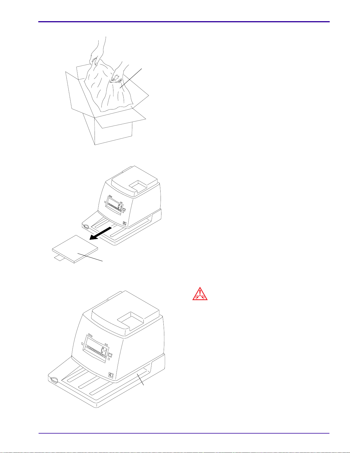
BAG
H139_0014ACA
H139_0014AC
Unpacking the ID CAMERA
[5] Take the aluminum shielding BAG containing the
ID CAMERA out of the CAMERA BOX.
(a) Cut the BAG carefully and remove the ID
CAMERA.
(b) Remove the dessicant container from the
back of the ID CAMERA.
[6] Remove the PROTECTIVE SHEET from the ID
CAMERA.
PROTECTIVE SHEET
H139_0073ACA
H139_0073AC
CASSETTE
SLOT
H139_0001ACB
H139_0001AC
Check the Contents of the ACCESSORY BOX
Caution
When moving the ID CAMERA, do not put your hands
into the CASSETTE SLOT. Hold the ID CAMERA from
underneath. If excessive force is applied to the
CASSETTE SLOT, it might break.
990602 – January 1996 7
Page 8

INSTALLATION INSTRUCTIONS
Check that the ACCESSORY BOX contains the following:
• 2 spare MAIN EXPOSURE LAMPS 10 W, 4.6 V
• 1 spare UL CSA FUSE 3 A
• 1 spare TUV FUSE 1 A
• 2 spare CLOCK LAMPS
• 2 POWER CORDS: one for 100 or 120 V AC operation and one for 220, 230, or 240 V AC operation
• Warranty card
• “Cassette Window Description” and “Error Code Label” Part No. 1C0069
• “Character Label” for Serial No. identification when replacing the A-P or P-A CIRCUIT BOARDS
• Publication No. 2B6405, containing the Operator Manual, Installation Instructions, and the Service Guide
Important
Remember to keep the shipping carton and all packing material for the customer, in case it is necessary to
return the ID CAMERA for service.
8 January 1996 – 990602
Page 9

Section 4: Setting Up the ID CAMERA
H139_0066AC
SCREW (6)
COVER PLATE
POWER SWITCH
H139_0066ACA
Selecting the Correct Voltage
Warning
Dangerous Voltage.
Removing the POWER SWITCH COVER PLATE
Setting Up the ID CAMERA
[1] Check that the ID CAMERA is de-energized and that the POWER CORD is disconnected.
[2] Turn the ID CAMERA on its side.
[3] Remove the 6 SCREWS from the POWER SWITCH COVER PLATE, and remove the POWER SWITCH
COVER PLATE.
[4] Use a 3.0 mm ALLEN WRENCH to remove the 3 SCREWS from the bottom of the ID CAMERA.
[5] Turn the ID CAMERA upright.
Caution
Do not stretch the RIBBON CABLE attached to the COVER and CPU BOARD.
990602 – January 1996 9
Page 10

INSTALLATION INSTRUCTIONS
Removing the COVER
COVER
RIBBON
CABLE
CPU BOARD
H139_0042CCA
H139_0042CA
[6] Remove the COVER carefully, and disconnect the RIBBON CABLE from the CPU BOARD. Turn the COVER
upside down and place the COVER next to the ID CAMERA.
10 January 1996 – 990602
Page 11

Setting Up the ID CAMERA
Installing a new FUSE
Selecting the Correct Voltage
VOLTAGE SELECTOR
FUSE CAP
FUSE
VOLTAGE
SELECTOR
H139_0034ACA
H139_0034AC
[7] Usea FLATHEADSCREWDRIVER toremovethe
FUSE CAP holding the FUSE.
[8] Measure the source voltage.
[9] Use a flat WIDEBLADE SCREWDRIVER, or
COIN, to turn the VOLTAGE SELECTOR to the
correct voltage.
[10] Insert the correct FUSE, install the new FUSE
CAP, and press and turn clockwise.
H139_0019ACA
H139_0019AC
Selecting the Date Format
SWITCHES 1 and 2 of DP SW1 control the date format.
Note
If you are installing and setting up the ID CAMERA for
the first time, you can keep the COVER off andbegin at
Step7 on Page 14for the procedure forsetting the Date
Format and with Step 7 on Page 17 for the procedure
for setting the Time Format.
[11] Connectthe RIBBONCABLE to theCPU BOARD,
and place the COVER on the ID CAMERA.
[12] Turn the ID CAMERA on its side.
[13] Install the 3 SCREWS, and the 6 SCREWS and
POWER SWITCH COVER PLATE removed
earlier.
[14] Turn the ID CAMERA upright.
990602 – January 1996 11
Page 12

INSTALLATION INSTRUCTIONS
H
Warning
Dangerous Voltage.
Removing the POWER SWITCH COVER PLATE
POWER SWITC
COVER PLATE
SCREW (6)
H139_0066ACA
H139_0066AC
[1] Check that the ID CAMERA is de-energized and that the POWER CORD is disconnected.
[2] Turn the ID CAMERA on its side.
[3] Remove the 6 SCREWS from the POWER SWITCH COVER PLATE, and remove the POWER SWITCH
COVER PLATE.
[4] Use a 3.0 mm ALLEN WRENCH to remove the 3 SCREWS from the bottom of the ID CAMERA.
[5] Turn the ID CAMERA upright.
Caution
Do not stretch the RIBBON CABLE attached to the COVER and CPU BOARD.
12 January 1996 – 990602
Page 13

Removing the COVER
H139_0042CA
H139_0042CCA
CPU BOARD
CABLE
RIBBON
COVER
Setting Up the ID CAMERA
[6] Remove the COVER carefully, and disconnect the RIBBON CABLE from the CPU BOARD. Turn the COVER
upside down and place the COVER next to the ID CAMERA.
990602 – January 1996 13
Page 14

INSTALLATION INSTRUCTIONS
Locating the DATE DIP SWITCHES
DATE DIP SWITCHES
1
2
3
4
5
6
7
OFF
DP SW1
8
CPU
BOARD
[7] To select themonth-day-year format, to set 02-28-
93, for example:
(a) DIP SWITCH 1 to ON and
(b) DIP SWITCH 2 to OFF
[8] To select the day-month-year format, to set 28-
02-93, for example:
(a) DIP SWITCH 1 to OFF and
(b) DIP SWITCH 2 to ON
[9] To select theyear-month-day format, to set 93-02-
28, for example:
(a) DIP SWITCH 1 to ON and
(b) DIP SWITCH 2 to ON
[10] Connectthe RIBBONCABLE to theCPU BOARD,
and place the COVER on the ID CAMERA.
[11] Turn the ID CAMERA on its side.
[12] Install the 3 SCREWS, and the 6 SCREWS and
POWER SWITCH COVER PLATE removed
earlier.
[13] Turn the ID CAMERA upright.
[14] Energize the ID CAMERA while holding the
DENSITY DECREASE BUTTON. This will reset
the microprocessor.
SW2
H139_0033CCA
H139_0033CC
Selecting the Time Format
SWITCHES 1 and 2 of SW2 control the time format.
Warning
Dangerous Voltage.
14 January 1996 – 990602
Page 15

Removing the POWER SWITCH COVER PLATE
H139_0066AC
SCREW (6)
COVER PLATE
POWER SWITCH
H139_0066ACA
Setting Up the ID CAMERA
[1] Check that the ID CAMERA is de-energized and that the POWER CORD is disconnected.
[2] Turn the ID CAMERA on its side.
[3] Remove the 6 SCREWS from the POWER SWITCH COVER PLATE, and remove the POWER SWITCH
COVER PLATE.
[4] Use a 3.0 mm ALLEN WRENCH to remove the 3 SCREWS from the bottom of the ID CAMERA.
[5] Turn the ID CAMERA upright.
Caution
Do not stretch the RIBBON CABLE attached to the COVER and CPU BOARD.
990602 – January 1996 15
Page 16

INSTALLATION INSTRUCTIONS
Removing the COVER
COVER
RIBBON
CABLE
CPU BOARD
H139_0042CCA
H139_0042CA
[6] Remove the COVER carefully, and disconnect the RIBBON CABLE from the CPU BOARD. Turn the COVER
upside down and place the COVER next to the ID CAMERA.
16 January 1996 – 990602
Page 17

Setting Up the ID CAMERA
Locating the Time Date DIP SWITCHES
DP SW1
CPU
BOARD
[7] To select the 12-hour time format, set:
(a) DIP SWITCH 1 to OFF and
(b) DIP SWITCH 2 to OFF
[8] To select the 24-hour time format, set:
(a) DIP SWITCH 1 to ON and
(b) DIP SWITCH 2 to OFF
[9] Connectthe RIBBONCABLE to theCPU BOARD,
and place the COVER on the ID CAMERA.
[10] Turn the ID CAMERA on its side.
[11] Install the 3 SCREWS, and the 6 SCREWS and
POWER SWITCH COVER PLATE removed
earlier.
[12] Turn the ID CAMERA upright.
[13] Energize the ID CAMERA while holding the
DENSITY DECREASE BUTTON. This will reset
the microprocessor.
SW2
TIME DIP SWITCHES
O
F
F
1
2
H139_0032CCA
H139_0032CC
Setting the Date and Time
[1] Check that the ID CAMERA is connected to a power source with a reliable earth ground. Energize the ID
CAMERA.
990602 – January 1996 17
Page 18

INSTALLATION INSTRUCTIONS
DATE BUTTONS
DATE DISPLAY
DENSITY
DECREASE
BUTTON
PM
TIME BUTTONS
TIME DISPLAY
WINDOW
BUTTON
2
1
4
3
8
765
10
9
LCD PANEL
[2] Set the date and time:
(a) Press the DENSITY INCREASE andDENSITY DECREASE BUTTONS at the same time. The values in
the DATE and TIME DISPLAYS will flash.
(b) Press the DATE BUTTONSto select the date you want. The DATE BUTTONSare programmed to the date
format selected earlier.
• For example, if your date format is month/day/year, the left DATE BUTTON controls the month, the
middle DATE BUTTON controls the day, and the right DATE BUTTON controls the year.
• If your date format is day/month/year, the left DATE BUTTON controls the day, the middle DATE
BUTTON controls the month, and the right DATE BUTTON controls the year.
• If your date format is year/month/day, the left DATE BUTTON controls the year, the middle DATE
BUTTON controls the month and the right DATE BUTTON controls the day.
(c) Continue to press the appropriate DATE BUTTONS until the correct date is displayed on the LCD.
(d) Press the TIME BUTTONS to select the time. The TIME BUTTONS are programmed to the time format
selected earlier, either a 12- or 24-hour clock.
• In both the 12- and 24-hour time formats, the leftTIME BUTTON controls the hour, and theright TIME
BUTTON controls the minutes.
(e) Continue to press the TIME BUTTONS until the correct time is displayed on the LCD PANEL.
(f) PRESS the DENSITY INCREASE BUTTON only, approximately 2 - 3 seconds,until the DATE and TIME
DISPLAYS stop flashing.
DENSITY
INCREASE
BUTTON
H139_0003BCA
H139_0003BC
Note
• The DENSITY BUTTONS are deactuated while the DATE and TIME DISPLAYS are flashing.
• The time or date cannot be changed if a PATIENT ID CARD is in either the P-A or A-P CARD SLOT.
18 January 1996 – 990602
Page 19

Clearing the Date and Time
DATE BUTTONS
DATE DISPLAY
DENSITY
DECREASE
BUTTON
Setting Up the ID CAMERA
PM
TIME BUTTONS
TIME DISPLAY
WINDOW
BUTTON
2
1
4
3
8
765
10
9
DENSITY
INCREASE
BUTTON
LCD PANEL
H139_0003BCA
To clear the date and time, or set the date and time to “0”, de-energize the CAMERA, press the DENSITY
DECREASE BUTTON and then press the POWER BUTTON. This clears, or resets, the microprocessor.
H139_0003BC
990602 – January 1996 19
Page 20

INSTALLATION INSTRUCTIONS
Section 5: Performing the Density Step Test Procedure
Density Step Test Procedure
The purpose of the Density Step Test Procedure is to choose the preferred density exposure for the customer. It is
important that the customer be involved in this procedure.
This is a good opportunity for you to instruct the customer in the operation of the ID CAMERA. As you perform the
StepTest, allow the customer to help prepare CASSETTES and ID CARDS, and to make a few of the test exposures.
Afterward, give the Operator Manual to the customer and answer any questions.
[1] Prepare 10 ID CARDS bynumbering each from 1 to 10. Prepare 10 CASSETTES by loading with unexposed
film. Use the smallest CASSETTE available.
[2] Exposeeach CASSETTE to an increasing density,making sure to changethe ID CARD foreach exposure. Use
the ID CARD marked “1” for DENSITY SETTING 1, and use the ID CARD marked “2” for DENSITY SETTING
2, and so on. Make the exposures with the CASSETTES used most often.
[3] Process the film. Choose the best exposure. Check the density with a densitometer if one is available. The
background density from a bright white card should be 1.2. Record the preferred exposure for the customer.
Note
If you cannot get satisfactory results, see the Service Manual section “Adjusting Potentiometers” for instructions on
adjusting the LAMP POTENTIOMETERS.
20 January 1996 – 990602
Page 21

Section 6: Publication History
Print Date Pub. No. ECO No. Affected Pages File Name Notes
August 1993 990602 All Pages 3294ii_a.doc First printing.
January
1996
990602 2504-435 All Pages ii3294_1_435.doc Added 4SL information.
Publication History
990602 – January 1996 21
Page 22

Kodak, Kodaflex, Min-R
and
X-Omatic
are trademarks.
ii3294_1.fm
Printed In USA
Health Imaging
EASTMAN KODAK COMPANY ● ROCHESTER, N.Y. 14650
 Loading...