

Page 1

KODAK
VERSAMARK DS5110 Printer
Operator’s Manual
Kodak Versamark, Inc.
Page 2

Page 3

KODAK VERSAMARK
DS5110 Printer
Operator’s Guide
Page 4

FCC Compliance Statement
This equipment has been tested and found to comply with the limits for a Class A digital device, pursuant to Part 15 of the FCC Rules. These
limits are designed to provide reasonable protection against harmful interference when the equipment is operated in a commercial environment.
This equipment generates, uses, and can radiate radio frequency energy and, if not installed and used in accordance with the instruction manual, may cause harmful interference to radio communications. Operation of this equipment in a residential area is likely to cause harmful interference, in which case the user will be required to correct the interference at his own expense.
Note: Good quality, shielded (braided shielded) cables must be used for the RS-232-C and Centronics interfaces.
Canadian EMI Compliance Statement
Le présent appareil numérique n’émet pas de bruits radioélectriques dépassant les limites applicables aux appareils numériques de la classe A
prescrites dans le Règlement sur le brouillage radioélectrique édicté par le ministère des Communications du Canada.
This digital apparatus does not exceed the Class A limits for radio noise emissions from digital apparatus set out in the Radio Interference Regulations of the Canadian Department of Communications.
EMI-CISPR 22/EN 55 022/CE Marking
Warning: This is a Class A product. In a domestic environment, this product may cause radio interference in which case the user may be
required to take adequate measures.
KODAK VER SA MARK DS5110 Printer
Operator’s Guide
Part Number Media Revision Date Description ECN
0114214-602
0114214-603
Print
PDF
001 07/2004 Revised manual format xxxxx
© Eastman Kodak Company, 2004. All rights reserved.
This document contains proprietary information of Kodak Versamark, Inc. or its licensors and is their exclusive property. It may not be
reproduced without a written agreement from Kodak Versamark, Inc. No patent or other license is granted to this information.
The software described in this document is furnished under a license agreement. The software may not be used or copied except as provided
in the license agreement.
Kodak Versamark, Inc. makes no warranty of any kind with regard to the contents of this document, including, but not limited to, the implied
warranties of merchantability and fitness for a particular purpose. Kodak Versamark shall not be liable for any errors or for compensatory,
incidental or consequential damages in connection with the furnishing, performance, or use of this document or the examples contained herein.
Information concerning products not manufactured by Kodak Versamark, Inc. is provided without warranty or representation of any kind, and
Kodak Versamark, Inc. will not be liable for any damages resulting from the use of such information.
0114214-602
0114214-603 08/2004 Printed in U.S.A.
Page 5

Scope
This guide describes operating, troubleshooting, and maintenance procedures for
the K
ODAK VERSAMARK DP5110 printer (DP5110).
This guide assumes that the reader is the operator, who is responsible for printing
jobs, troubleshooting common printing problems, and performing routine
maintenance. The reader should have a basic knowledge of computers and the
printing environment in which the printer is being used.
When other system components or system software programs are required to
complete a procedure, appropriate manuals are referenced.
Operator’s Guide iii
Page 6

Text Notations
Safety Notations
This manual uses the following typogra phi ca l conv en tio ns .
This style Refers to
Ready
go
ENTER
[NEXT] Buttons and lights on the printer operator panel.
Save Software command buttons and sections of dialog boxes, such as
→ Open
File
ALT+F1
ALT, TAB
xx,yy
jobfile.dat File names.
Text displayed by the software.
Anything you type, exactly as it appears, whether referenced in text or
at a prompt.
Special keys on the keyboard, such as enter, alt, and spacebar.
group boxes, text boxes, and text fields.
A menu and a specific menu command.
Pressing more than one key at the same time.
Pressing more than one key in sequen ce .
Variable in error messages and text.
The following definitions indicate safety precautions to the operator.
Note: Information that needs to be brought to the reader’s attention.
Caution: A situation where a mistake could result in the destruction of data or system-type
damage.
!
WARNING
A potential hazard that could result in serious injury or death.
!
DANGER
An imminent hazard that will result in serious injury or death.
iv
Page 7

Service and Support
Technical equipment support is available 24 hours a day, 7 days a week.
Software and applications support is available 8:00 a.m. to 5:00 p.m. EST/EDT,
Monday through Friday.
Call for telephone or on-site tec hnical support; to order pa rts or supplies; to re quest
documentation or product information.
Phone Fax
U.S.A., Canada, and worldwide (+1-800-472-4839)
+1-937-259-3739
Europe +41-21-806-0404 +41-21-806-1920
Asia/Pacific Rim +65-6744-6400 +65-6744-6700
Japan +81-3-3256-2613 +81-3-3256-2616
Updated service information http://www.kodakversamark.com
Customer support customer@kodakversamark.com
+1-937-259-3808
Operator’s Guide v
Page 8

Page 9

Contents
Chapter 1. Getting Started
Printer Components ............................................................................. 1-2
Printer ............................................................................................ 1-2
Operator Panel .............................................................................. 1-3
Printhead and Umbilical................................................................. 1-3
Fluid Compartment ........................................................................ 1-4
Supporting the Printhead ..................................................................... 1-5
Setting Up the Printhead...................................................................... 1-7
Determining Substrate Movement................................................. 1-7
Locating the Print Array ................................................................. 1-7
Printing at 90° ................................................................................ 1-8
Positioning Multiple Printheads...................................................... 1-8
Determining Cue Distance and Cue Delay......................................... 1-10
Tach Encoder .............................................................................. 1-10
Cue Sensor.................................................................................. 1-11
Cue Distance......................................................................... 1-11
Cue Delay.............................................................................. 1-12
Document and Image Lengths........ ...... ....... ...... ....... ...... ................... 1-13
Operator’s Guide vii
Chapter 2. Basic Operation
Operator Panel Functions .................................................................... 2-2
Panel Buttons ................................................................................ 2-2
Panel Lights.................................................................................. 2-4
Operating Procedures .......................................................................... 2-5
Turning On the Printer ..................................................... ...... ....... . 2-5
Bypassing the POC Test and Fluid System................................... 2-6
Turning On the Fluid System When Idle........................................ 2-6
Turning On the Fluid System When Bypassed.............................. 2-6
Idle Time Guidelines...................................................................... 2-7
Turning Off the Fluid System ......................................................... 2-7
Turning Off the Printer and the Fluid System ................................ 2-7
Clearing Errors............................................................................... 2-7
Page 10

Contents
Replacing Ink and Replenisher....... ....... ...... ........................................ 2-8
Moving the Printer................................................................................ 2-9
Power Failure..................................................................................... 2-10
Chapter 3. Troubleshooting
Printing Test Patterns .......................................................................... 3-2
Identifying Printing Problems............................................................... 3-3
Voltage Defects............................................................................. 3-3
Phase Defects............................................................................... 3-5
Dirty Printhead Components ......................................................... 3-6
Miscellaneous Problems..................................... ...... .............. 3 -9
Chapter 4. Maintenance
Required Tools and Supplies............................................................... 4-1
Daily Maintenance ............................................................................... 4-2
Cleaning the Printhead Bottom Cover........................................... 4-2
Cleaning the Printhead.................... ...... ....... ...... ....... ...... ....... ...... . 4-3
Periodic Maintenance .......................................................................... 4-4
Cleaning the Air Filter................................... ...... ....... ...... ....... ....... 4-4
Replacing the Mist Filter................................................................ 4-5
Corrective Maintenance....................................................................... 4-7
Cleaning the Printhead Catcher Bottom Plate............................... 4-7
Swabbing the Printhead................................................................ 4-8
Glossary
viii
Page 11

Figures
Figure 1.1 Printer components .................................................... 1-2
Figure 1.2 Printhead mount......................................................... 1-5
Figure 1.3 Printhead mount stand ............................................... 1-6
Figure 1.4 Print array................................................................... 1-7
Figure 1.5 Printing at 90×............................................................ 1-8
Figure 1.6 Multiple printer dimensions......................................... 1-9
Figure 1.7 Tach encoder ........................................................... 1-10
Figure 1.8 Cue sensor example ................................................ 1-11
Figure 1.9 Cue distance and cue delay..................................... 1-12
Figure 1.10 Document parameters.............................................. 1-13
Figure 2.1 Operator panel buttons and lights.............................. 2-2
Figure 2.2 Ink and replenisher bottles......................................... 2-8
Figure 2.3 Printer - rear view..................................................... 2-10
Figure 3.1 Test pattern ................................................................ 3-1
Figure 3.2 Test print example...................................................... 3-2
Figure 4.1 Removing the printhead bottom cover ....................... 4-2
Figure 4.2 Cleaning the printhead bottom cover ......................... 4-3
Figure 4.3 Removing the air filter ................................................ 4-4
Figure 4.4 Removing the mist filter fitting.................................... 4-6
Figure 4.5 Replacing the mist filter.............................................. 4-6
Figure 4.6 Cleaning the catcher bottom plate.............................. 4-8
Operator’s Manual ix
Page 12

Page 13

Chapter 1. Getting Started
The DH5110 printhead is 1.0 inch (2.54 cm) wide. Vertical resolution is
fixed at 120 dpi and spans the width of the printhead array. Horizontal
resolution is in the direction of substrate movement and can be set to 120
or 240 dpi. Resolution is measured in dots per inch (dpi). The DS5110 is
capable of printing 100-percent variable data at a print speed of up to
1000 fpm.
After installation, basic setup procedures must be performed before
printing can begin. Along with a brief overview of the system components,
this chapter describes the required setup procedures, which include
supporting the printhead, setting up the printhead, printing at angles,
positioning multiple printheads, and determining cue values.
Operator’s Guide 1 - 1
Page 14
Chapter 1. Getting Started
Printer Components
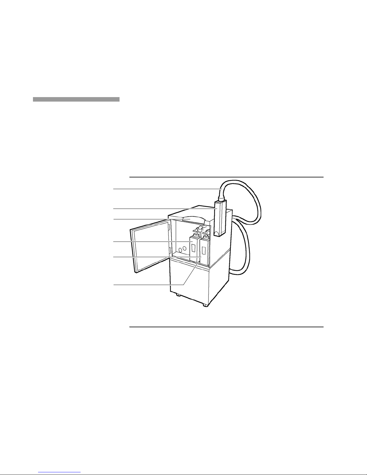
Printer Components
Umbilical
Printhead
Operator panel
Replenisher bottle
The printer contains the following components (Figure 1.1):
• Printer
• Operator panel
• Printhead with attached umbilical
• Fluid compartment.
Figure 1.1 Printer components
Ink bottle
Fluid compartment
Printer
The printer, which includes all of the components within the printer
cabinet, accepts print data and commands that determine job setup and
control printer functions. The printer receives this information from a
controller and translates it into a bitmapped format that is sent to the
printhead through the umbilical.
1 - 2
Page 15

Chapter 1. Getting Started
Printer Components
Operator Panel
The five buttons appearing across the top of the operator panel control
printer operations, such as powering the printer and fluid system on and
off, opening and closing the eyelid, and cleaning the printhead. The seven
lights appearing across the bottom of the panel report operating
conditions such as low fluid levels, errors, and the detection of tach and
cue signals.
Printhead and Umbilical
Caution: To prevent damage to the printhead or printed circuit board components,
use the supplied wrist grounding strap when handling these components;
also, handle circuit boards only by edges free of connectors.
The printhead contains the print array , a row of holes (orifices) from which
the jets of ink are formed. The printhead provides a 1.06-inch (2.69 cm)
print width.
A covering, called the eyelid, protects the print array from damage and
dust and keeps fluids from leaking during printer startup and shutdown.
When the printer is idle, the eyelid should be closed. During printing, the
eyelid must be open to allow ink to reach the substrate.
The standard 12-ft (3.6576 m) or optional 24-ft (7.3152 m) umbilical
connects the printhead to the fluid system. The umbilical contains the fluid
tubes and electrical cables that transfer ink and data between the fluid
system and the printhead.
Operator’s Guide 1 - 3
Page 16

Chapter 1. Getting Started
Printer Components
Fluid Compartment
Note: Use only Kodak Versamark-approved inks.
The fluid compartment, contains the ink and replenisher bottles.
Replenisher maintains the relative concentration of ink to water. A light on
the operator panel comes on when a fluid bottle or external ink container
is depleted and needs to be replaced.
The printer has quick-release couplings in the lines to the ink and
replenisher bottles to allow you to connect larger containers located
outside of the cabinet.
See Chapter 2 for fluid bottle and external container replacement
procedures.
1 - 4
Page 17
Supporting the Printhead
Chapter 1. Getting Started
Supporting the Printhead
The printhead support must hold the printhead steady to protect it from
vibration. The support must also hold the printhead within 0.0 to 1.00 inch
(2.54 cm) of the substrate, and support the weight of the printhead and
umbilical. Printhead height restrictions vary from model to model.
Maximum printhead height is 1.0 inch (2.54 cm).
Two support options are available: the printhead mount and the printhead
mount stand. Refer to the installation instructions shipped with the
supports for assembly and installation instructions. The supports for the
one-inch and two-inch printheads vary only slightly. The printhead mount
holds the printhead over a label base or document transport (Figure 1.2).
Figure 1.2 Printhead mount
Operator’s Guide 1 - 5
Page 18
Chapter 1. Getting Started
Supporting the Printhead
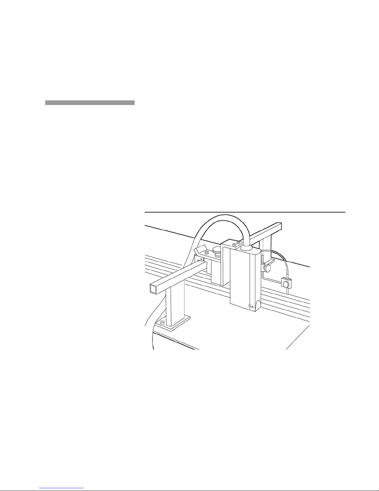
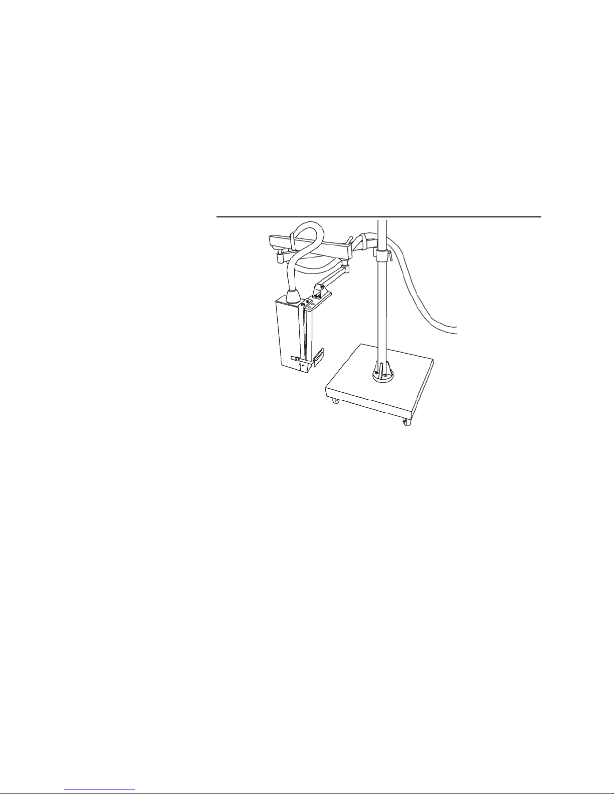
The printhead mount stand consists of an extendable arm, mounted on a
steel base with casters. The printhead mount stand provides a stable,
mobile printhead support (Figure 1.3).
Figure 1.3 Printhead mount stand
1 - 6
Page 19
Setting Up the Printhead
Chapter 1. Getting Started
Setting Up the Printhead
Proper printhead setup helps to ensure print quality. Multiple printer
configurations and angle printing require certain restrictions or
considerations when positioning the printhead.
Determining Substrate Movement
The printhead has a series of dot indentations appearing on the sides of
the printhead cover to indicate the direction of normal substrate
movement. These dots decrease in size in the direction of normal
substrate movement.
Locating the Print Array
The printhead has a dot indentation on the seam of the printhead cover
which is the largest dot indentation. The seam indicates the location of the
print array (Figure 1.4).
Figure 1.4 Print array
Print array
Operator’s Guide 1 - 7
Page 20
Chapter 1. Getting Started
Setting Up the Printhead
Substrate moving vertically
Print array
Printing at 90°
The printhead starts up, prints, and shuts down from all angular positions
between 6 ft (1.83 m) above and 2 ft (0.61 m) below the base plate of the
printer.
When printing with the substrate at a 90° angle to the ground, position the
printhead so that the front cover of the printhead faces the ground and the
print array faces the substrate, as shown in Figure 1.5.
Figure 1.5 Printing at 90°
Positioning Multiple Printheads
Position multiple printheads as closely together as possible. The most
downstream printhead (the last printhead to print) must finish printing
before the next substrate passes under the cue sensor. (See the section
“Determining Cue Distance and Cue Delay” in this chap ter.)
The following dimensions, shown in Figure 1.6, need to be considered:
• Feedstroke - the substrate length plus the distance between
substrates
• Cue distance - the distance between the cue sensor and the print
array of each printhead
• Image length - the length of the image being printed.
For proper positioning, feedstroke must be equal to or greater than
the cue distance for each printhead plus the image length.
1 - 8
Page 21

Chapter 1. Getting Started
Setting Up the Printhead
You can further verify accurate printhead positioning by ensuring that the
distance between substrates is equal to or greater than the cue distance
for the most downstream printhead.
In multiple printer configurations, all printers to be used for the job must
be selected to print and must be configured according to the system
software being used. (See your system software operator's manual for
details.)
Figure 1.6 Multiple printer dimensions
Distance between substrates
Feedstroke
Cue
sensor
Image
length
Substrate direction
Cue
distance
Synchronization (Cue Checking) options must be enabled for all printers
and all printers must be set for the same cue error response. (See your
system software manual for details on setting this parameter.)
Operator’s Guide 1 - 9
Page 22

Chapter 1. Getting Started
Determining Cue Distance and Cue Delay
Determining Cue Distance and Cue Delay
The cue sensor and tach encoder, each mounted on the document
transport, are required for proper printing.
The information provided by these devices determines when printing
occurs.
Tach and cue installation are application specific. See the
for general installation guidelines.
Guide
Installation
Tach Encoder
The tach encoder generates pulses that indicate the travel distance and
speed of the transport (Figure 1.7). The tach rate must match (or be a
multiple of) the print resolution being used. (See your system software
operator's manual for details on selecting print resolution and tach rate.)
Figure 1.7 Tach encoder
1 - 10
Page 23

Cue amplifier
Chapter 1. Getting Started
Determining Cue Distance and Cue Delay
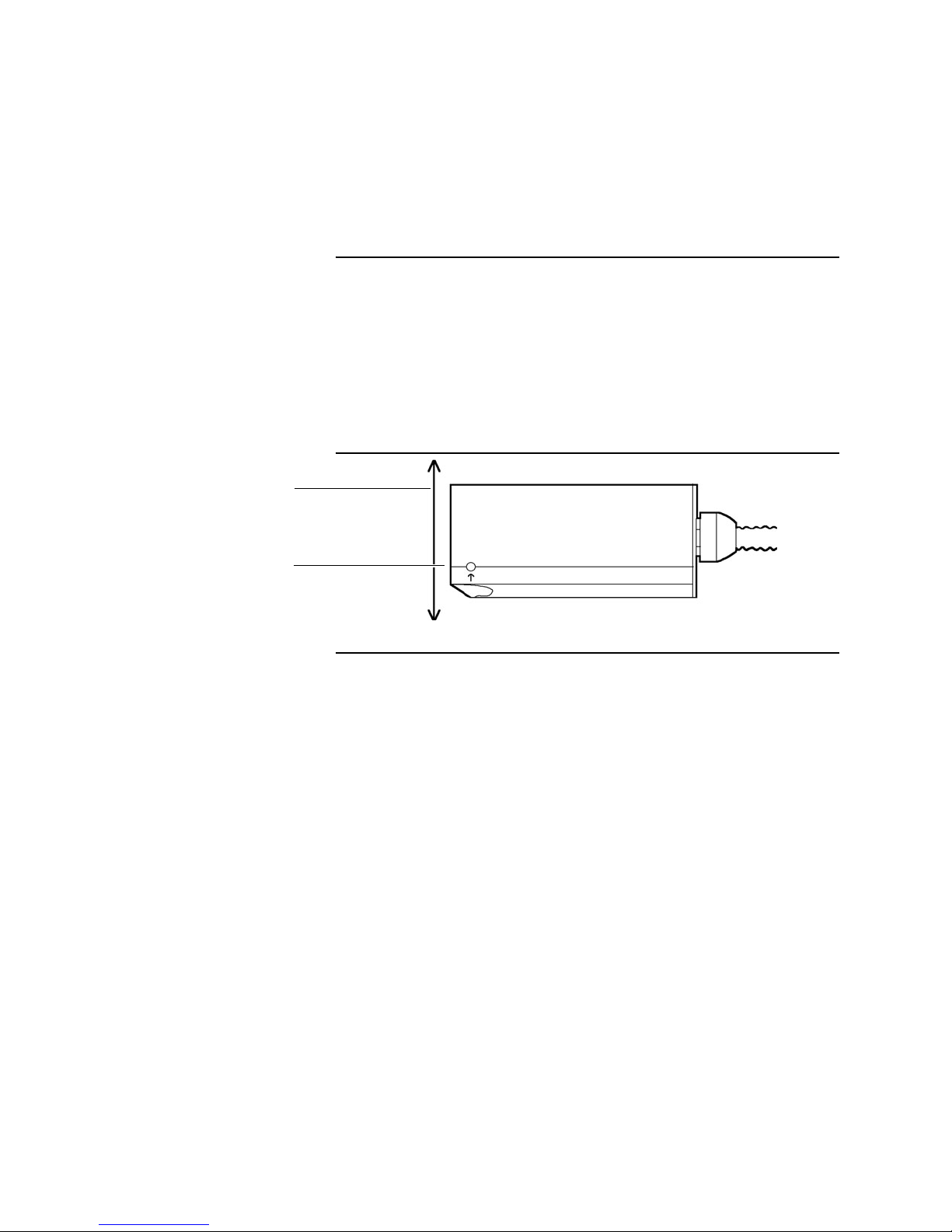
Cue Sensor
The cue sensor detects the substrate as it passes under the print array.
Two cue values, cue distance and cue delay, must be entered in the
system software for printing to occur at the desired position within the
image area. (Figure 1.8 shows an example of one type of cue sensor
used with the printers.)
Figure 1.8 Cue sensor example
Cue Dist ance
Cue distance is the distance from the cue sensor to the print array (Figure
1.9). The minimum cue distance is 1.0 inch (2.54 cm). The maximum cue
distance is dependent on the print resolution in the direction of substrate
movement and is shown in Table 1.1 on page 1-14. To determine cue
distance, slowly move the substrate under the cue sensor until the light on
the cue amplifier goes out. Stop the piece and measure the distance from
leading edge of the piece to the print array.
Operator’s Guide 1 - 11
Page 24

Chapter 1. Getting Started
Determining Cue Distance and Cue Delay
Cue Delay
Cue delay is the distance from the leading edge of the piece (or
substrate) to the start of the image (Figure 1.9). The value entered for cue
delay is based on the image position required for the job.
Figure 1.9 Cue distance and cue delay
Substrate direction
Substrate
Cue
delay
Array
Printhead
Cue distance
Cue
sensor
The minimum value for cue delay is zero. A value of zero causes printing
to start right at the edge of the substrate. The maximum value allowed for
cue delay depends on the print resolution in the direction of substrate
movement. See Table 1.1 on page 1-14.
Enter the cue distance and cue delay values at job setup using the
procedures described in your systems software
Operator’s Guide.
Adding the cue distance and cue delay tells the printer how long to wait
before starting to print after the leading edge of the substrate is detected
by the cue sensor. Tach pulses are counted to determine when the
substrate has moved from the cue sensor to the print position.
1 - 12
Page 25

Document and Image Lengths
Two other parameters are required by the printer: document length and
image length. These two parameters are illustrated in Figure 1.10.
Figure 1.10 Document parameters
Piece
Image length is used by the printer to set aside the amount of buffer
space required for the image. Document length is used to stop printing if
the image is still being printed when the document length is reached.
Chapter 1. Getting Started
Document and Image Len gth s
Image
Length
Leading
Edge
Cue Delay
Document
Length
When printi n g o n di scr et e pi ec es of su b st ra t e, t he cue sensor detects th e
leading and trailing edges of the substrate and, in effect, provides a startof-document and an end-of-document signal. In this case, the document
length could be specified as being shorter than the substrate length to
make sure that printing stops before a sensitive area, such as a
preprinted area, is reached.
If printing on a web, the start-of-document signal may come from a cue
mark on the web or from a mechanical cue generator. In this case, the
document length is used as an end-of-document indicator.
The maximum image length is fixed by the physical size of the printer
page buffer and is dependent on the horizontal resolution being used.
Maximum image length is 136 inches (345.4 cm) at 120 dpi and 68 inches
(172.7 cm) at 240 dpi.
Operator’s Guide 1 - 13
Page 26

Chapter 1. Getting Started
Document and Image Lengths
The maximum document length is dependent upon horizontal resolution
and is the same as those shown for cue distance and cue delay in Table
1.1.
Enter the values for document length (sometimes called substrate length)
and image length at job setup using the procedures described in your
systems software Operator’s Guide.
Table 1.1 Maximum distances
Horizontal
Resolution
120 dpi 120 inches (304.8 cm)
240 dpi 60 inches (152.4 cm)
Maximum Cue Distance,
Cue Delay, and Document Length
1 - 14
Page 27

Chapter 2. Basic Operation
This chapter describes basic operating procedures for the printer.
Operating procedures include turning the printer on and off, bringing the
printer online, and replacing fluids. Moving and idle time guidelines are
also described.
Operator’s Guide 2 - 1
Page 28

Chapter 2. Basic Operation
Operator Panel Functions
Operator Panel Functions
The printer operator panel allows you to perform basic operating
procedures, such as turning the printer on and cleaning the printhead
(Figure 2.1). Using the buttons and lights on the panel, you can perform
specific functions and monitor the printer's performance.
Figure 2.1 Operator panel buttons and lights
Standby
Add Replenisher
For Future Use
Test Print
Add Ink
Open Eyelid
Error
Clean Printhead
Data
Tach
Printer On
Power
Cue
Panel Buttons
The five buttons across the top of the operator panel perform online
operations. The lights above each button indicate the status of specific
printer conditions.
The [STANDBY], [TEST PRINT], [OPEN EYELID], and [PRINTER ON]
buttons provide more than one function. When you initially press one of
these four buttons, the printer performs the function associated with the
name of the button. The light above the button comes on to indicate the
button is the On position.
2 - 2
If you press the button again, the printer reverses the function and the
light goes off. For example, when you press [OPEN EYELID] the first
time, the eyelid opens. The light above [OPEN EYELID] flashes. When
you press [OPEN EYELID] again, the eyelid closes and the light goes off.
The [CLEAN PRINTHEAD] button initiates one function. Each time you
press this button, a printhead clean is performed.
Page 29

Chapter 2. Basic Operation
Operator Panel Functions
Table 2.1 describes the functions associated with each button and
identifies the On and Off positions for each button.
Table 2.1 Operator panel buttons
Button Name On Position Off Position
ST ANDBY If the fluid system is off ,
turns on the fluid
system with the eyelid
closed.
Light is on.
TEST PRINT Starts printing test
patterns.
Light is on.
OPEN EYELID
Opens the eyelid.
1
Light is on.
CLEAN
PRINTHEAD
Initiates a printhead
clean.
If the fluid system is
on, turns off the fluid
system and closes the
eyelid.
Light is off.
Stops printing test
patterns.
Light is off.
Closes the eyelid.
Light is off.
None
Light is on during the
printhead clean; goes
off when complete.
PRINTER ON Turns on the printer
and the fluid system.
[PRINTER ON] and
[STANDBY] come on.
1. [OPEN EYELID] is also used to clear errors and to turn the printer on with the fluid
system and power-on confidence (POC) test bypassed. (See the operating procedures
section of this chapter for the POC test bypass procedure.)
Turns off the printer
and the fluid system.
[PRINTER ON] and
[STANDBY] go off.
Operator’s Guide 2 - 3
Page 30

Chapter 2. Basic Operation
Operator Panel Functions
Panel Lights
The eight lights across the bottom of the operator panel indicate specific
operating conditions. Table 2.2 describes the lights and the conditions
they represent.
Table 2.2 Operator panel lights
Light Definition Operating Condition
ADD REPLENISHER Flashes when replenisher is low.
ADD INK Flashes when ink is low.
ERROR Flashes for an inkjet (or pri nth ead ) sh ort
error; remains lit for any other type of
error. (See your system software
operator's manual for details on error
messages.)
DATA READY Lights up when data is available for
printing.
TACH Lights up each time a tach pulse is
received.
CUE Lights up each time the cue changes
POWER Lights when the printer has electrical
2 - 4
state. Cue signals cannot be received
without tach pulses.
power connected.
Page 31

Operating Procedures
Note: Ensure the printer has electrical power connected before turning on the
Chapter 2. Basic Operation
Operating Procedures
The procedures used to perform online operations are described in the
following section.
Turning On the Printer
To ensure proper communication between the printer and other system
components, always turn on components in the following sequence:
1. Printer
2. Tape drive (if installed)
3. Host controller.
printer. (The [POWER] light is lit.)
Turn on the printer and the fluid system by pressing [PRINTER ON].
During the power-on cycle, various operator panel lights come on or flash.
When the cycle is complete, the [PRINTER ON] and [STANDBY] lights
remain lit, indicating the fluid system is on.
Under normal operating conditions, 70°F (21°C) and 50% relative
humidity, the power-on cycle takes about 7 minutes to complete.
Note: If the printer power-on cycle is not successful, repeat the power-on
procedure a minimum of three times before requesting assistance from
service personnel.
Operator’s Guide 2 - 5
Page 32

Chapter 2. Basic Operation
Operating Procedures
Bypassing the POC Te st and Fluid System
The printer can be turned on with the fluid system bypassed. Use this
method when the printer is to remain idle for more than 1 hour or during
troubleshooting.
To turn the printer on with the fluid system and POC test bypassed, press
and hold [OPEN EYELID]; press and release [PRINTER ON]. When all
lights on the operator panel come on, release [OPEN EYELID]. The
[PRINTER ON] light remains lit.
Turning On the Fluid System When Idle
To bring the fluid system out of idle, press [STANDBY]. The [STANDBY]
light flashes while the fluid system powers up and remains lit when the
fluid system is completely powered up. (See “Idle Time Guidelines” on
page 2-7.)
Turning On the Fluid System When Bypassed
To turn on the fluid system when it has been bypassed, press [CLEAN
PRINTHEAD]. The [CLEAN PRINTHEAD] light flashes during the
cleaning cycle and then goes off. The [STANDBY] light remains lit.
You may want to print a test pattern to ensure that print quality is
satisfactory (See Chapter 3, ”Troubleshooting”.)
2 - 6
Page 33

Chapter 2. Basic Operation
Operating Procedures
Idle Time Guidelines
You can leave the printer on indefinitely without printing; however, if
leaving the printer idle for more than 1 hour, you can extend ink life by
following the guidelines in Table 2.3.
Table 2.3 Idle time guidelines
Idle Time Procedure
Less than 1 hour Leave printer and fluid system on and close the eyelid.
1 to 7 hours Turn off fluid system. Perform a printhead clean to restart.
7 hours to 7 days Turn off fluid system and printer. Power on printer and fluid
More than 7 days
Open the eyelid to continue.
system to restart.
See the 5000 Series
shutdown procedures.
Service Guide
for long-term
Turning Off the Fluid System
To turn off the fluid system, press [STANDBY]. During power down, the
[STANDBY] light flashes at a faster rate than it does at power up; the
[STANDBY] goes off when the fluid system is completely powered down.
Some ink remains in the printhead. The printer can be left in this state for
up to 7 hours.
Turning Off the Printer and the Fluid System
To turn off the printer and the fluid system, press [PRINTER ON]. The
[PRINTER ON] and [STANDBY] lights flash rapidly and go off when
power-off is complete (approximately 5 minutes).
Operator’s Guide 2 - 7
Clearing Errors
When an error is detected, the [ERROR] light comes on. If the error is an
inkjet short (IJ-42) error, the [ERROR] light flashes. To clear an error,
press [OPEN EYELID]. The status of the eyelid remains the same.
Page 34

Chapter 2. Basic Operation
Replacing Ink and Replenisher
Replacing Ink and Replenisher
Ink and replenisher bottles or external ink containers must be replaced as
required. The bottles are located in the fluid compartment (Figure 2.2).
Figure 2.2 Ink and replenisher bottles
Quick-disconnect
couplings for external
containers
Replenisher
Ink
When ink or replenisher is low, [ADD INK] or [ADD REPLENISHER]
flashes. If the supply reaches a critical level before being replaced, an
error occurs (and the [ERROR] light comes on).
The fluid bottles can also be replaced while the printer is on or printing. To
replace an ink or a replenisher bottle, perform the following procedure:
1. Open the fluid compartment door.
2. Unscrew the ink cap from the empty bottle and set the bottle aside.
Note: Before installing the replacement bottle, verify that the sticker on the
replacement bottle matches the emblem that appears on the fluid
compartment panel.
3. Remove the cap and seal from the replacement bottle. Retain the cap
for future bottle disposal.
2 - 8
Page 35

Moving the Printer
Chapter 2. Basic Operation
Moving the Printer
4. Position the replacement bottle inside the fluid compartment so that
the collar sits on top of the metal supports. Pull up on the collar of the
bottle while sliding the bottle into the compartment.
5. Attach the ink fitting to the top of the replacement bottle.
6. Close the compartment door.
7. Install the cap from the replacement bottle on the empty bottle.
8. Dispose of the empty bottle in accordance with governmental
regulations.
When moving the printer, refer to the following procedure and Figure 2.3
to prevent damage to the printhead and umbilical.
Caution: To avoid fluid leakage that could cause an inkjet (or printhead) short,
ensure the printer and the fluid system are turned off before moving the
printer.
1. If the printer is on, turn it off by pressing [PRINTER ON].
2. Press the circuit breaker switch located on the back of the printer to
the Off position.
3. Unplug the printer from the electrical outlet.
4. Coil the umbilical around the umbilical hanger located on the back of
the printer and cradle the printhead in the coils.
Operator’s Guide 2 - 9
Page 36

Chapter 2. Basic Operation
Power Failure
Umbilical hanger
Circuit breaker switch
Power Failure
Figure 2.3 Printer - rear view
The printer can withstand a power interruption of up to ½ the operating
cycle without affecting operation.
During a complete power loss, the eyelid closes to prevent ink spills.
Setup parameters are saved.
When power is restored, the printer does not automatically power back
on. To turn on the printer and the fluid system, press [PRINTER ON]. The
power-on cycle is performed.
See your system software operator's manual for information on restarting
a job.
2 - 10
Page 37

Figure 3.1 Test pattern
Chapter 3. Troubleshooting
This chapter describes the troubleshooting tools used to determine the
cause of common printing problems and identifies the maintenance
procedures used to correct the problems. These tools include test
patterns and text prints.
Test patterns can be printed by pressing [TEST PRINT] on the operator
panel. A test pattern consists of a pattern of lines designed to verify print
quality or to reveal specific print problems. Figure 3.1 provides an
example of a test pattern.
Operator’s Guide 3 - 1
By comparing the print quality of the test patterns you print with the test
pattern examples provided in this chapter, you can determine the cause
of the printing problem.
Page 38

Chapter 3. Troubleshooting
Printing Test Patterns
Printing Test Patterns
You can also use the test print examples provided in this chapter to
determine the causes of printing problems by comparing the print quality
of the test prints to the print quality of your print data. Figure 3.2 provides
an example of a test print.
Figure 3.2 Test print example
The maintenance procedures used to correct the printing problems are
described in Chapter 4. Other corrective actions are referenced as
required.
Perform the following procedure to print test patterns from the printer
operator panel:
1. Turn on the printer and the fluid system by pressing [PRINTER ON].
2. Open the eyelid by pressing [OPEN EYELID].
3. Press [TEST PRINT]. The [TEST PRINT] light comes on. The [DATA
READY] light comes on, indicating data is available for printing.
4. Start the document transport. The [TEST PRINT] light flashes,
indicating test patterns are printing. The [TACH] light flashes,
indicating tach pulses are being received. The [CUE] light flashes to
indicate cue signals are being received.
5. To stop printing, press [TEST PRINT] again; the [TEST PRINT] light
goes off.
Note: The host controller cannot communicate with the printer while test
patterns are being printed.
3 - 2
Page 39

Identifying Printing Problems
This section provides examples of test patterns and test prints showing
common print problems. Possible causes and suggested corrective
actions to be taken to correct the problems are also described.
Perform each step in a corrective action in the order described. After
completing each corrective action, print test patterns or run the job;
examine the print quality of the output. If necessary, repeat the corrective
action until the problem is corrected.
The following printing problems are caused by incorrect voltage settings.
(See your system software operator's manual for details on adjusting
printhead voltage settings.)
Voltage Defect s
Missing or Misdirected Drops
Missing or misdirected drops usually appear in the sixth bar from the
left of the test pattern when the charge voltage applied to the
printhead is too high.
Chapter 3. Troubleshooting
Identifying Printing Problems
Operator’s Guide 3 - 3
#6
Page 40

Chapter 3. Troubleshooting
Identifying Printing Problems
#2 #3
Extra Dots
At even higher voltages, extra drops may occur. Extra drops may also
appear between the second and third bars of a test pattern when the
charge voltage is too low.
At the highest voltages an inkjet (or printhead) short may occur. When
this error occurs, the [ERROR] light flashes. (See your system
software operator's manual for details on error messages.)
Voltage defects appear on test prints as extra dots of ink that appear
near the center of the printed image or across the bottom the image.
3 - 4
Page 41

Chapter 3. Troubleshooting
Identifying Printing Problems
To correct printing problems caused by voltage defects, perform the
following steps:
1. Clean the catcher bottom plate as described in Chapter 4.
2. Record the current voltage setting.
3. Raise or lower the voltage level by 5 volts. (See your system software
operator's manual for details on adjusting printhead voltage settings.)
4. Continue adjusting the voltage level until the problem is corrected.
5. If the problem persists, reset the voltage level to its original setting.
6. Perform the printhead cleaning procedure described in Chapter 4.
7. If the problem persists, repeat the printhead cleaning procedure.
8. When all other corrective actions fail, perform the printhead swabbing
procedure described in Chapter 4.
Phase Defects
To correct a printing problem caused by phase defects, perform the
following steps:
1. Verify that the problem is not caused by interference by cleaning the
catcher plate as described in Chapter 4.
2. Record the current phase setting.
3. Raise or lower the phase setting by 5 units. (See your system
software operator's manual for details on adjusting the printhead
phase setting.)
4. Continue adjusting the phase setting until the problem is corrected.
5. If the problem persists, reset the phase setting to its original setting.
6. Perform the printhead cleaning procedure described in Chapter 4.
7. Repeat the printhead cleaning procedure until the problem is
corrected.
Operator’s Guide 3 - 5
Page 42

Chapter 3. Troubleshooting
Identifying Printing Problems
Dirty Printhead Components
The print problems described in the following section are caused by dirty
printhead components.
Streakers
Streakers appear on test patterns as solid black lines.
Streakers appear on test prints as horizontal bands of ink.
Streakers are usually caused by dirty printheads or improper voltage
settings. At high voltage settings, light streakers appear near the sixth
bar of a test pattern; low voltage settings cause more solid streakers.
To correct printing problems caused by streakers, perform the following
steps:
1. Perform the printhead cleaning procedure described in Chapter 4.
2. If the problem persists, repeat the printhead cleaning procedure.
3. If the problem still persists, clean the printhead bottom cover as
described in Chapter 4.
4. Perform steps 2, 3, and 4 from the voltage defect procedure
described in the previous section.
5. If the problem persists, repeat the printhead cleaning procedure.
3 - 6
Page 43

Chapter 3. Troubleshooting
Identifying Printing Problems
6. If the problem still persists, repeat the printhead cleaning procedure.
7. When all other corrective actions fail, perform the printhead swabbing
procedure described in Chapter 4.
Interference
Interference appears on a test pattern as a ragged line of print or
scattered dots.
Interference appears on test prints as a solid, horizontal line of
missing print.
This printing problem indicate s inte rfer enc e with the flight of dro ps (also
known as drop interference). This condition is the most common print
problem and is usually caused by particles of dust adhering to the
printhead bottom cover. Drop interference can also be caused by dust on
the eyelid or inside the printhead assembly.
To correct a printing problem caused by interference, perform the
following steps:
1. Clean the printhead bottom cover and the eyelid (See Chapter 4).
2. Clean the catcher bottom plate (See Chapter 4).
3. If the problem improves or has moved, clean the catcher bottom plate
again.
4. Perform the printhead cleaning procedure described in Chapter 4.
5. If the problem persists, perform the phase defect procedure. See
“Phase Defects” on page 3-5.
Operator’s Guide 3 - 7
Page 44

Chapter 3. Troubleshooting
Identifying Printing Problems
Irregular Gaps
Irregular gaps appearing in the test pattern at powerup usually
indicate that air is trapped within the printhead. Irregular gaps can
also be caused by a concentration of ink.
Perform a printhead clean to remove the air bubbles or ink concentration.
(See Chapter 4 for printhead cleaning procedures.)
Irregular gaps may also appear when the voltage or phase setting is
incorrect; however, always perform a printhead clean before attempting to
adjust the printhead voltage level. (See your system software operator's
manual for details on adjusting printhead voltage and phase levels.)
A Single Line of Dots
A single line of dots indicates that the printhead needs to be cleaned.
(See Chapter 4 for printhead cleaning procedures.)
3 - 8
Page 45

Chapter 3. Troubleshooting
Identifying Printing Problems
Miscellaneous Problems
The following printing problems are caused by several different sources.
Smears
Smears appear on test prints as areas of smudged ink.
Print smears are caused by outside sources, such as substrate
stacking, wet print, and paper guide malfunctions. Check for these
types of problems after the substrate has passed under the printhead.
Smears can also be caused by improper printhead height. Printhead
height is the distance between the bottom of the printhead and the
substrate. (See Chapter 1 for details on printhead height.)
1. Make sure there is clearance between the substrate and the
printhead bottom cover.
2. Verify that the software parameter for printhead height matches the
actual physical printhead height; adjust the printhead height
parameter to match the printhead's position as required. (See your
system software operator's manual for details on adjusting printhead
height.)
Distortion
Distortion appears on test prints as wavy or irregular characters or
characters of varying width and height.
Operator’s Guide 3 - 9
Page 46

Chapter 3. Troubleshooting
Identifying Printing Problems
To correct printing problem s cau se d by distorti on, per form the fol lowing
steps:
1. If characters are wavy or irregular, verify that the current printhead
height falls within the appropriate range for the printer being used, as
described in Chapter 1.
2. If possible, decrease the printhead height to move the printhead
closer to the substrate.
3. Verify that the software parameter for printhead height matches the
actual physical printhead height; adjust the printhead height
parameter to match the printhead's position as required. (See your
system software operator's manual for details on adjusting printhead
height.)
Elongation
Elongation appears on test prints as a consistent widening of
characters.
To correct elongated characters, perform the following steps:
1. Verify that the parameter settings defined for tach and cue are
correct. (See your system software operator's manual for details on
adjusting tach and cue.)
2. If the tach encoder is tracking paper speed incorrectly, verify that the
document transport is operating at the proper rate of speed.
Compression
To correct printing problems with compressed print, perform the
following procedure:
1. Verify that the parameter settings defined for tach and cue are
correct. (See your system software operator's manual for details on
adjusting tach and cue.)
3 - 10
Page 47

Chapter 3. Troubleshooting
Identifying Printing Problems
2. If the tach encoder is tracking paper speed incorrectly, verify that the
document transport is operating at the proper rate of speed.
3. If using a wheeled tach, verify that the wheel is traveling on the belt or
on the substrate, not on roller or other surface.
4. Make sure that the rubber on the wheel is not worn excessively.
5. Make sure that the tach encoder is properly grounded to avoid
interference by high-frequency noise.
Narrow Print
Narrow print appears on text prints as a consistent narrowing of
characters.
To correct printing problems with narrow print, perform the following
procedure:
1. Adjust the parameter settings defined for tach and cue. (See your
system software operator's manual for details on adjusting tach and
cue.)
2. If the substrate flow appears to be hindered, check the document
transport for proper operation.
Improper Print Density
The number of drops of ink used to produce one dot of an image is
known as print density. Print quality can be improved by changing
print density, which makes the printed image lighter or darker. (See
your system software operator's manual for details on defining print
density.)
Operator’s Guide 3 - 11
Page 48

Page 49

Chapter 4. Maintenance
This chapter describes the routine and corrective maintenance
procedures that may be performed by an operator.
Routine maintenance must be performed to ensure the printer continues
to operate properly. As operator, you perform two types of routine
maintenance on the printer: daily and periodic.
Corrective maintenance procedures are performed to correct printing
problems, as directed by the troubleshooting procedures described in
Chapter 3.
Required Tools and Supplies
The following tools are required to perform the mai nten anc e proc edure s
described in this chapter:
• Compressed air
• Mist filter
• Spare printhead bottom cover
• Kodak Versamark-supplied, foam-tipped swabs
• Distilled water
• Wrist grounding strap.
Operator’s Guide 4 - 1
Page 50

Chapter 4. Maintenance
Daily Maintenance
Daily Maintenanc e
Daily printer maintenance consists of cleaning the printhead bottom cover
and the printhead. Perform these two tasks every 8 hours of run time and
when the printhead bottom cover or printhead appears to be dirty. Both
tasks require less than 10 minutes to perform.
Cleaning the Printhead Bottom Cover
To clean the printhead bottom cover, perform the following procedure:
1. Turn off the printer by pressing [PRINTER ON].
2. Position the printhead so that the bottom cover is easily accessible;
insert an index finger into the slot on the bottom cover and carefully
pull the cover off. Figure 4.1 illustrates the printhead position used
when the printhead is not installed on a mount.
Figure 4.1 Removing the printhead bottom cover
4 - 2
Page 51

Chapter 4. Maintenance
Daily Maintenance
3. Rinse the bottom cover in water (especially around the print array
opening) until all ink buildup is removed (Figure 4.2). For stubborn
buildup, soak the cover in water overnight.
Figure 4.2 Cleaning the printhead bottom cover
!
WARNING
Before disposing of ink buildup, dilute it with water until colorless. Follow
all federal, state, and local regulations regarding chemical disposal.
4. Replace the bottom cover with the spare cover provided at
installation; be sure to align the slot on the bottom cover with the print
array.
5. Let the replaced bottom cover air dry.
Cleaning the Printhead
The printhead may be cleaned at any time during printer operations. The
printhead should be cleaned under the following circumstances:
• Before printing, when the POC is bypassed
• After every 8 hours of run time
• When the printhead bottom cover is cleaned
• When the printhead is dirty
• When required by the procedure being performed.
To perform a printhead clean, press [CLEAN PRINTHEAD]. The fluid
system powers down and the eyelid closes. When the cleaning cycle is
complete, [CLEAN PRINTHEAD] goes off and [STANDBY] comes on,
indicating the fluid system is on.
Operator’s Guide 4 - 3
Page 52

Chapter 4. Maintenance
Periodic Maintenance
Periodic Maintenance
Periodic maintenance consists of cleaning the air filter and replacing the
mist filter. The frequency at which these two tasks are performed depends
on the amount of dust in the printer environme nt.
Cleaning the Air Filter
Remove and clean the air filter, mounted on the back of the printer when it
appears dirty. Perform the following steps to clean the filter:
1. Grasp the sides of the air filter and press down to free the top of the
air filter from the upper bracket; lift the air filter out of the bottom
bracket (Figure 4.3).
Figure 4.3 Removing the air filter
4 - 4
2. Rinse the air filter in tap water, shaking out the excess water.
3. Air dry or use compressed air to dry the air filter.
4. When the air filter is completely dry, seat the bottom edge of the filter
in the lower bracket and press down on the upper edge of the air filter
until it slips under the upper bracket.
Page 53

Chapter 4. Maintenance
Periodic Maintenance
Replacing the Mist Filter
The mist filter, located inside the fluid compartment, controls the
accumulation of moisture inside the printer. A mist filter installed must be
replaced approximately every 500 hours of operation or when the filter
becomes clogged with ink. In general, the frequency of mist filter
replacement depends largely on the operating environment. Drier
environments clog the mist filter faster.
To replace the mist filter, perform the following steps:
Note: Because the mist filter is clogged with ink, wear gloves when performing
this procedure.
1. Open the fluid compartment door and locate the mist filter assembly,
which is centered above the ink and replenisher bottles.
2. Press the release button on the left side of the filter fitting to release
the mist filter assembly from its mount (Figure 4.4).
3. Pull the filter fitting out far enough to remove the mist filter.
4. Remove the filter from the filter fitting.
5. Insert the new filter into the filter fitting, allowing approximately 1.5
in. (3.81 cm) of the filter to protrude (Figure 4.5).
6. Reinstall the mist filter fitting assembly and close the fluid
compartment door.
Operator’s Guide 4 - 5
Page 54

Chapter 4. Maintenance
Periodic Maintenance
Release button
Mist filter
Filter fitting
Figure 4.4 Removing the mist filter fitting
Figure 4.5 Replacing the mist filter
Mist filter
Filter fitting
4 - 6
Page 55

Corrective Maintenance
Chapter 4. Maintenance
Corrective Maintenance
This section describes the corrective maintenance procedures used to
correct printing problems identified by the troubleshooting procedures in
Chapter 3.
Cleaning the Printhead Catcher Bottom Plate
This section describes the procedure used to clean the printhead catcher
bottom plate. This procedure should always be performed before
attempting to swab the printhead.
To prevent damage to the printhead and printed circuit board
components, follow anti-static safety precautions and use the K
V
ERSAMARK-supplied wrist grounding strap when handling the printhead
and circuit boards. Handle circuit boards only by edges free of
connectors.
1. Press [STANDBY].
2. Press [OPEN EYELID].
ODAK
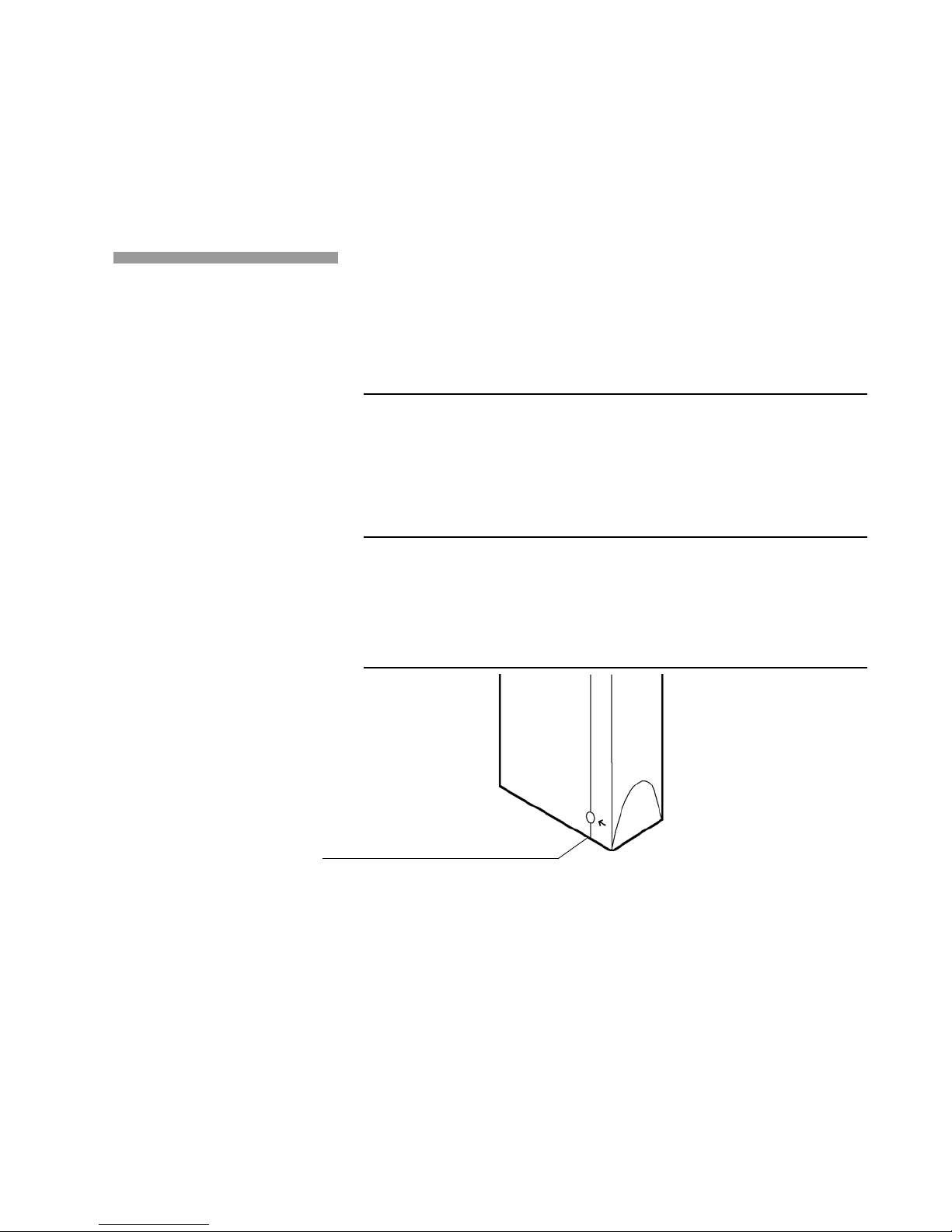
3. Position the printhead at a 90° angle.
4. Remove the printhead bottom cover by inserting an index finger into
the slot on the bottom cover and carefully pulling the cover off.
5. Using a K
ODAK VERSAMARK-supplied, polyester wipe dampened with
distilled water, clean the area of the catcher bottom plate (Figure 4.6).
6. Press [CLEAN PRINTHEAD].
Operator’s Guide 4 - 7
Page 56

Chapter 4. Maintenance
Corrective Maintenance
Catcher bottom plate
Printhead bottom
Figure 4.6 Cleaning the catcher bottom plate
Swabbing the Printhead
This section describes the procedure used to swab the printhead. This
procedure should only be performed under advisement from K
ERSAMARK service personnel and only after all other corrective actions
V
have proven unsuccessful in correcting the problem.
Caution: To prevent damage to the printhead and its printed circuit board
components, follow anti-static safety precautions and use the K
V
ERSAMARK-supplied wrist grounding strap when handling the printhead
and circuit boards. Handle circuit boards only by edges free of
connectors.
1. Exit any system software program.
ODAK
ODAK
2. Turn the printer off by pressing [PRINTER ON]. ([PRINTER ON] goes
off, while [POWER] remains on.)
3. Remove the printhead bottom cover from the printhead housing
assembly.
4. Loosen the captive screw on the printhead front cover and remove
the cover.
5. Remove the eyelid assembly as described in the following procedure:
Caution: To avoid damaging the eyelid seal, handle the seal carefully when
removing the eyelid assembly.
a. Remove the hitch pin in the eyelid pivot shaft.
b. Remove the eyelid by pressing slightly at the front to relieve the
pressure on the eyelid pivot shaft and pushing the shaft from the
4 - 8
Page 57

Chapter 4. Maintenance
Corrective Maintenance
hitch pin end and pulling it out the other. The eyelid assembly and
solenoid plunger are connected in the DH5110 printhead.
Caution: Because the printhead charge leads and orifice plate are very fragile
components, read steps 6 and 7 thoroughly before attempting to perform
the described procedures.
6. Saturate a K
ODAK VERSAMARK-supplied foam swab with replenisher
from the replenisher bottle.
Note: Use only fresh replenisher to wet the swab. Cotton swabs must not be
used to swab printhead components; small-tipped swabs can be used.
7. Lightly press the corner of the swab into the charge leads and orifice
plate corner and gently drag the swab back and forth over the charge
leads and orifice plate; repeat this swabbing motion two or three
times using both sides of the swab.
Caution: To avoid damaging the orifice plate or charge leads, do not scrub the
printhead with the swab or drag the swab past the ends of the orifice
plate.
8. Re-install the eyelid assembly as described in the following
procedure:
c. Set eyelid springs into holes inside the printhead frame.
d. Align the pin holes and slide the eyelid pivot shaft through the
printhead eyelid mounting brackets and the printhead. Secure the
eyelid with the hitch pin in the eyelid pivot shaft.
e. Push on the eyelid arm to manually open and close the eyelid to
verify that the eyelid has been installed correctly. The eyelid
should move freely.
9. Reinstall the printhead front cover as described in the following
procedure:
a. Position the printhead front cover on the printhead housing
assembly by squeezing the printhead rear cover at the area of
overlap.
b. Secure the printhead front cover to the printhead housing assem-
bly by tightening the captive screw.
Operator’s Guide 4 - 9
Page 58

Chapter 4. Maintenance
Corrective Maintenance
10. Reinstall the printhead bottom cover on the printhead housing; verify
that the opening on the bottom cover is aligned with the print array
opening on the printhead assembly.
11. Return the printhead to its normal operating position.
12. Turn the printer on by pressing [PRINTER ON].
4 - 10
Page 59

Glossary
catcher bottom plate The component of the catcher plate that
contains a row of electric leads that control drops of ink. When a charge
lead is activated, it imparts a charge to the ink drop that causes the ink
drop to be attracted to the catcher. When a lead remains deactivated, the
drop of ink remains uncharged and falls to the substrate.
charge voltage A parameter in the system software that determines
the voltage applied to the printhead, which charges drops of ink, attracting
them to the catcher or leaving them uncharged so that they hit the
substrate. (Also called printhead volts or volts.)
charge phase The parameter in the system software that determines
when the charge voltage is applied to the printhead. Charge phase is
measured in counts. (Also called printhead phase or phase.)
cue A signal that represents the start of a document. A cue signal
occurs each time the cue sensor detects the leading edge of a piece of
substrate or a pre-printed cue mark on the substrate.
cue delay The distance from the leading edge of a piece to the start of
the image.
cue distance The distance from the cue sensor to the print array.
cue error A parameter in the system software that allows the operator
to determine how a cue or piece overrun error is handled.
cue mark A pre-printed mark on a web that, in most cases, indicates
the start of a new document.
cue sensor A device mounted on the document transport that detects
the beginning of a document. The beginning can be indicated by marks
on a web or the leading edges of pieces of substrate.
Operator’s Guide
Page 60

Glossary
distortion A printing problem characterized by wavy or irregular
characters that occurs when the printhead is positioned too far away from
the substrate.
document A complete image as defined in the input data. A document
may include more than one page of data. Most common data preparation
establishes one document for each cue mark on a web.
document transport A device used to move the substrate or pieces
during printing.
dot 1. The smallest mark that can be printed by the printer.
2. A unit of measure related to the resolution of the printhead and tach
encoder. For example, at 120-dpi resolution, a distance of one dot equals
1
/120 in.
downstream In a multiple printer configuration, the last printer to print.
dpi Dots per inch, a measure of print resolution.
drop interference A printing problem characterized by a ragged line of
print or scattered dots, which indicate an interference with the flight of
drops. Drop interference is usually caused by particles of dust adhering to
the printhead bottom cover. Drop interference may also be caused by
dust adhering to the eyelid or to the inside of the printhead assembly.
elongation A printing problem characterized by elongated characters
that occurs when the parameters set for tach and cue are incorrect or the
tach encoder is incorrectly tracking the substrate speed.
extra dots A printing problem characterized by extra drops of ink,
which occurs when the charge voltage is too high.
eyelid The part of the printhead that opens to allow uncharged drops to
fall to the substrate. When closed, the eyelid protects the interior of the
printhead from damage and dust and seals the printhead during power-on
and power-off to prevent fluid leakage.
feedstroke A measure men t used in mul tip le pr int er configur at ion s to
determine where an image is printed on the substrate. Feedstroke equals
the piece length plus the distance between pieces.
filament A short, continuous stream of ink extending from the orifice,
which is broken into drops by the measured application of a physical
vibration.
Page 61

Glossary
fluid compartment The area inside the printer cabinet that contains
the ink and replenisher bottles.
fluid supply The ink and re plenisher supplies.
font A collection of characters that have the same typeface, style,
weight and point size.
fpm Feet per minute; 1 fpm equals 0.3048 meters per minute.
idle time Any time during which the printer is either turned on and not
printing or turned off.
image The information printed, including text and graphics.
image length The length of the image to be printed.
image width The width of the print array.
ink jet The stream of ink made up of the filament and drops coming
from one orifice.
irregular gaps A printing problem that usually occurs at powerup and
is characterized by missing areas of print. These gaps are caused by air
trapped within the printhead.
missing jet A white line that appears where ink should be, caused by
high charge voltage, contamination of the eyelid, or an open circuit.
online A term used to indicate that the printer is ready to print; the
printer and fluid station are on and the eyelid is open.
orifice A small hole through which pressurized ink extends in a
filament.
parameter An item in the system software for which a value can be
specified.
PC The component of the printer that accepts input data from tape or
disk, formats the data according to job setup instructions, and sends
character-coded image data to the printer. The PC is the primary operator
interface to the printer .
phase defect A printing problem that is caused by an improper charge
phase setting.
Operator’s Guide
Page 62

Glossary
piece A discrete segment of substrate upon which the image is printed.
For example, an envelope.
power-on cycle (POC) The sequence of procedures the printer
performs when it is turned on. The procedures include an internal
diagnostics test of the hardware, the warming of fluids, and a printhead
clean.
print array The 1.06-in. (2.69-cm) line of holes (orifices) in the
printhead through which ink jets are formed to create an image.
print density The number of dots of ink used to produce a dot of ink on
the substrate.
printhead The part of the printer that forms charged ink drops, allows
uncharged drops to fall on the substrate, and recovers charged drops for
return to the fluid cabinet. The printhead receives data in bitmap format
and, using ink and charge voltages, creates inkjet images.
print width The maximum width of the area that can be printed by the
printhead, usually provided in inches or dots.
printhead height The distance between the bottom of the printhead
and the substrate.
replenisher A fluid contained within a plastic bottle, mounted inside
the fluid compartment, that maintains the proper concentration of ink.
resolution The degree of sharpness of an image, measured in dpi.
shrunken print A printing problem characterized by shortened (or
shrunken) characters that occurs when tach and cue parameters are set
incorrectly or the document tra ns port is not operat ing properly.
streaker A recurring streak of ink (or solid black line) caused by one or
more jets printing continuously or by ink dripping from a part of the
printhead, creating a line (streak) on the substrate. Streakers are caused
by improper voltage levels and dirty printheads.
substrate The surface on which an image is printed. The substrate can
be a continuous sheet (web) or separate pieces of various types of
material.
substrate length The length of a piece of substrate.
Page 63

Glossary
tach 1. A measure of distance, as measured by the tach encoder.
2. A signal emitted by the tach encoder in response to the speed of the
substrate.
tach encoder A device that detects movement of the substrate and
generates tach signals in relationship to substrate speed.
test pattern A special image that can be printed by the printer operator
repeatedly to examine print quality.
test print A series of printed characters that the printer operator
compares against the text produced by the printer to troubleshoot printing
problems.
umbilical The part of the printer that transfers the fluids and signals
between the fluid system and the printhead through an assembly of hoses
and wiring encased within a flexible, protec ti ve shie ld.
voltage defect A printing problem that is caused by an improper
voltage setting.
web A continuous sheet of substrate.
Operator’s Guide
Page 64

Page 65

Page 66

0114214-602
0114214-603
© Kodak Versamark, Inc.
 Loading...