

Kodak Versamark DS5600 Series, Versamark DP5630, Versamark DP5640, Versamark DP5650 Operator's Manual
Page 1

0114332-603
Versamark DS5600 Series
Printing Systems
Operator Guide
Page 2

FCC Compliance Statement
This equipment has been tested and found to comply with the limits for a Class A digital device, pursuant to Part 15 of the FCC Rules. These
limits are designed to provide reasonable protection against harmful interference when the equipment is operated in a commercial environment.
This equipment generates, uses, and can radiate radio frequency energy and, if not installed and used in accordance with the instruction manual, may cause harmful interference to radio communications. Operation of this equipment in a residential area is likely to cause harmful interference, in which case the user will be required to correct the interference at his own expense.
Note: Good quality, shielded (braided shielded) cables must be used for the RS-232-C and Centronics interfaces.
Canadian EMI Compliance Statement
Le présent appareil numérique n’émet pas de bruits radioélectriques dépassant les limites applicables aux appareils numériques de la classe A
prescrites dans le Règlement sur le brouillage radioélectrique édicté par le ministère des Communications du Canada.
This digital apparatus does not exceed the Class A limits for radio noise emissions from digital apparatus set out in the Radio Interference Regulations of the Canadian Department of Communications.
EMI-CISPR 22/EN 55 022/CE Marking
Warning: This is a Class A product. In a domestic environment, this product may cause radio interference in which case the user may be
required to take adequate measures.
Versamark DS5600 Series Printing Systems Operator Guide
Part Number Media Revision Date Description ECN
0114332-603 PDF 02 09/2010 Revision for CS150 Version 4.0.2.0 K10566
Previous Releases
Part Number Media Revision Date Description ECN
0114332-602
0114332-603
© Kodak, 2010. All rights reserved.
This document contains proprietary information of Eastman Kodak Company or its licensors and is their exclusive property. It may not be
reproduced without a written agreement from Eastman Kodak Company. No patent or other license is granted to this information.
The software described in this document is furnished under a license agreement. The software may not be used or copied except as provided in
the license agreement.
Eastman Kodak Company makes no warranty of any kind with regard to the contents of this document, including, but not limited to, the implied
warranties of merchantability and fitness for a particular purpose. Eastman Kodak Company shall not be liable for any errors or for
compensatory, incidental or consequential damages in connection with the furnishing, performance, or use of this document or the examples
contained herein. Information concerning products not manufactured by Eastman Kodak Company. is provided without warranty or
representation of any kind, and Eastman Kodak Company will not be liable for any damages resulting from the use of such information.
Kodak and Versamark are trademarks of Eastman Kodak Company.
0114332-603 09/2010
Print
PDF
001 01/2008 Initial release with CS150 and CS150 UTS K7790
Page 3

Scope
This guide describes how to operate the Kodak Vers am ar k DS5600 Series
Printing Systems. These printing systems produce letter-quality, variable
data images using continuous inkjet technology at up to 500 fpm
(150 mpm) with print resolutions of 240x240, 240x480, 300x300, or
300x600 dots per inch (dpi).
The DS5600 series printing systems can be used for business forms, tag
and label, direct mail, booklets, bar coding, numbering, addressing,
personalization, and billing statements with or without spot color. These
printing systems are modular and can be configured for web or sheet-fed
presses, collators, mail bases, folders, and a variety of other inline and
offline finishing equipment.
For DS5600 operation, the following system requirements apply to the
system components:
• Kodak Versamark CS150 System Controller Software Dashboard
Version 4.0.1.0 or higher
• Microsoft Windows XP Professional with Service Pack 2.0
• Ethernet-compatible narrow-format printers (with Compact DS Main
board installed)
• Ethernet-compatible wide-format print stations (with Compact DS
Main board installed)
• Fluid Controller Software Release 5.000 or higher
For additional information about the components used in the DS5600
series printing systems, see the following publications:
• Kodak Versamark CS150 System Controller Software Getting Started
Guide
• Kodak Versamark DP5222 and DP5340 Printing Systems Operator’s
Guide
The procedures in this guide should be performed only by an operator
who has received on-site training from Kodak.
Operator Guide 3
Page 4

Scope
!
WARNING
!
DANGER
Text Notations
Safety Notations
Note: Information that needs to be brought to the reader’s attention.
Caution: A situation where a mistake could result in the destruction of data or
This manual uses the following typographical conventions.
This style Refers to
Ready
go
ENTER
[NEXT] Buttons and lights on the printer operator panel.
Save Software command buttons and sections of dialog boxes,
File Open
ALT+F1
ALT, TAB
xx,yy Variable in error messages and text.
jobfile.dat Fil e names.
Text displayed by the software.
Anything you type, exactly as it appears, whether referenced
in text or at a prompt.
Special keys on the keyboard, such as enter, alt, and
spacebar.
such as group boxes, text boxes, and text fields.
A menu and a specific menu command.
Pressing more than one key at the same time.
Pressing more than one key in sequence.
The following definitions indicate safety precautions to the operator.
system-type damage.
Service and Support
A potential hazard that could result in serious injury or death.
An imminent hazard that will result in serious injury or death.
Technical equipment support is available 24 hours a day, 7 days a week.
Software and applications support is available 8:00 a.m. to 5:00 p.m.
EST/EDT, Monday through Friday.
Call for telephone or on-site technical support; to order parts or supplies;
to request documentation or product information.
Phone Fax
U.S.A., Canada, and
worldwide
Europe +41-22-354-1400 +41-22-354-1480
Asia/Pacific Rim +65 6744 6400 +65 6744 6700
Japan +81-3-5621-2220 +81-3-5621-2221
+1-800-472-4839
+1-937-259-3739
+1-937-259-3808
4 DS5600 Series Printing Systems
Page 5

Contents
Chapter 1. Overview
DS5600 Configurations........................................................................................11
DS5600 Components ..........................................................................................13
System Controller... ... ... .... ... ... ... .......................................... ... .... ...................13
Print Stations............. ... .... ... ... ....................................... ... ... ... .... ... ... ... .... ......14
Printheads.....................................................................................................15
Fluid Containers............................................................................................15
System Operation...................................... ... ... .... ... ... ... .... ... ... ... ... .... ...................16
Chapter 2. Operation
System Preparation......... ... .... ... ... .......................................................................18
Startup Procedures..............................................................................................19
System Connections ........................................................... ... .... ... ... .............19
Startup Sequence .........................................................................................20
Controller Operation ............................................................................................21
Menus and Screens ......................................................................................22
Device Configuration.....................................................................................24
Database Configuration ................................................................................25
Job Selection... .... ... ... ....................................... ... ... .... ... ... ... ... .... ...................26
Job Printing ................................................................... ... ... ... .... ... ... ... .... ... ...27
Using Online Help .........................................................................................30
Print Station Operation ..................................................... ... ... ... ... .... ... ... ... .... ... ...31
Keyboard Controls ........................................................................................31
Screen Displays ............................................................................................32
Menu Screens........................................................................................ 32
Status Screens ...................................................................................... 33
Control Menu Procedures .............................................................................35
Service Menu Procedures......... .... ... ... ... ... .... ... ... ... .... ... ... ... ... .... ...................37
Parameters Menu Procedures ......................................................................38
Pressure Adjustment ....................................... .... ... ... ... ... .... ... ... ... .... ... .. 39
Vacuum Adjustment............................................................................... 39
Stim Adjustment..................................................................................... 40
Stim Phase Adjustment ......................................................................... 40
Charge Voltage Adjustment................................................................... 40
Standby.................................................................................................. 41
Setup Menu Procedures ...............................................................................41
Chapter 3. Messages
Message Displays................................................................................................44
Message List........................................................................................................44
Chapter 4. Operator Maintenance
Daily Maintenance...............................................................................................47
Printhead Bottom Cover Cleaning.................................................................47
Printhead Cleaning........................................................................................47
Weekly Maintenance ...........................................................................................48
Printhead Air Filter ........................................................................................48
Cabinet Air Filter ...........................................................................................48
Operator Guide 5
Page 6

Page 7

Figures
Figure 1.1 DS5600 printing system configuration...........................................12
Figure 1.2 DS5600 components, single DT3 system......................................13
Figure 1.3 DT3 Print Station ...........................................................................14
Figure 1.4 Typical ink-jet printing system........................................................16
Figure 2.1 Connections, CS150 controller on DT3 cabinet.............................19
Figure 2.2 Network hub and power connections, DT3 print station ................20
Figure 2.3 Main screen, CS150 software........................................................21
Figure 2.4 Diagnostics window .......................................................................22
Figure 2.5 Devices menu, Diagnostics screen................................................22
Figure 2.6 Select service setup window, CS150 software..............................24
Figure 2.7 Print job selection window .............................................................26
Figure 2.8 Database window ..........................................................................26
Figure 2.9 Configuring New Fields..................................................................27
Figure 2.10 Production window - after set up, CS150 ......................................27
Figure 2.11 Run window, CS150......................................................................29
Figure 2.12 Fluid controller software title screen..............................................31
Figure 2.13 Menu tree, DT3 print station software............................................32
Figure 2.14 Status screen layout............... ... .... ... ... ... .... ... ... ... ... .... ... ... ... .... ... ...33
Figure 2.15 Printhead Ready status screen......................................................33
Figure 2.16 Control Menu, DT3 print station software... ... ................................35
Figure 2.17 Parameters Adjustments screen, Control Menu............................35
Figure 2.18 Remote/Service Selection screen, Control Menu..........................35
Figure 2.19 Service Menu, DT3 print station software......................................37
Figure 2.20 Parameters Menu, DT3 print station software.. ... ... .... ... ... ... .... ... ...38
Figure 2.21 Setup Menu, DT3 print station software ........................................41
Figure 3.1 Print station operator terminal screen display................................43
Figure 3.2 Display screen with sample messages..........................................43
Figure 3.3 Error message during startup ........................................................44
Figure 4.1 Printhead air filter, DH6240 ...........................................................48
Figure 4.2 Cabinet filter, DT3 print station .....................................................48
Operator Guide 7
Page 8

Page 9

Tables
Table 1.1 Printhead performance..............................................................15
Table 2.1 System status display summary................................................34
Table 2.2 Control menu functions..............................................................36
Table 2.3 Service menu function............... ... ... ..........................................37
Operator Guide 9
Page 10

Page 11

DS5600 Configurations
Chapter 1. Overview
This overview describes Kodak Ve rs a ma rk DS5600 Series Printing
Systems in the following sections:
• DS5600 Configurations
• DS5600 Components
Configuration descriptions describe the various combinations of
components that can make up a system.
Component descriptions identify the controller, printers, and print stations
used in the DS5600, and the system nomencla tu re .
The DS5600 series supports up to four printers and print stations in the
following combinations:
• Kodak Versamark CS150 System Controller with two Kodak
Ve rs am ar k DP5600 Series Print Stations
• Kodak Versamark CS150 System Controller with one narrow-format
printer (Kodak Versamark DP5222 Printer or Kodak Versamark
DP5340 Printer) and two Kodak Versamark DP5600 Series Print
Stations
• Kodak Versamark CS150 System Controller with two narrow-format
printers (Kodak Versamark DP5222 Printer or Kodak Versamark
DP5340 Printer) and two Kodak Versamark DP5600 Series Print
Stations
• Kodak Versamark CS150 System Controller with three narrow-format
printers (Kodak Versamark DP5222 Printer or Kodak Versamark
DP5340 Printer) and one Kodak Versamark DP5600 Series Print
Station
The narrow-format printers support the following printheads:
• Kodak Versamark DH5222 Printheads, which has a 2.13" (5.41 cm)
print array and prints resolutions of 120x120 or 120x240 dpi
• Kodak Versamark DH5340 Printheads, which has a 1.07" (2.71 cm)
print array and prints resolutions of 240x240 or 240x480 dpi
The DP5600 series print station can support any of the following
printheads:
• Kodak Versamark DH5300 Printhead, which has a 2.77" (7.04 cm)
print array and prints resolutions of 300x300 or 300x600
• Kodak Versamark DH6300 Printhead, which has a 3.41" (8.66 cm)
print array and prints resolutions of 300x300 or 300x600
• Kodak Versamark DH6240 Printhead, which has a 4.27" (10.85 cm)
print array and prints resolutions of 240x240 or 240x480
Operator Guide 11
Page 12
Chapter 1. Overview
Second DP5600 series print station
CS150 on DS5600
CS150 on DS5000
or
DP5222
or
DP5340
2.13" DH5222
or
1.07" DH5340
DP5630
DP5640
or
DP5650
3.41" DH6300
2.77" DH5300
4.27" DH6240
or
Second, third and fourth printers
DS5600 Configurations
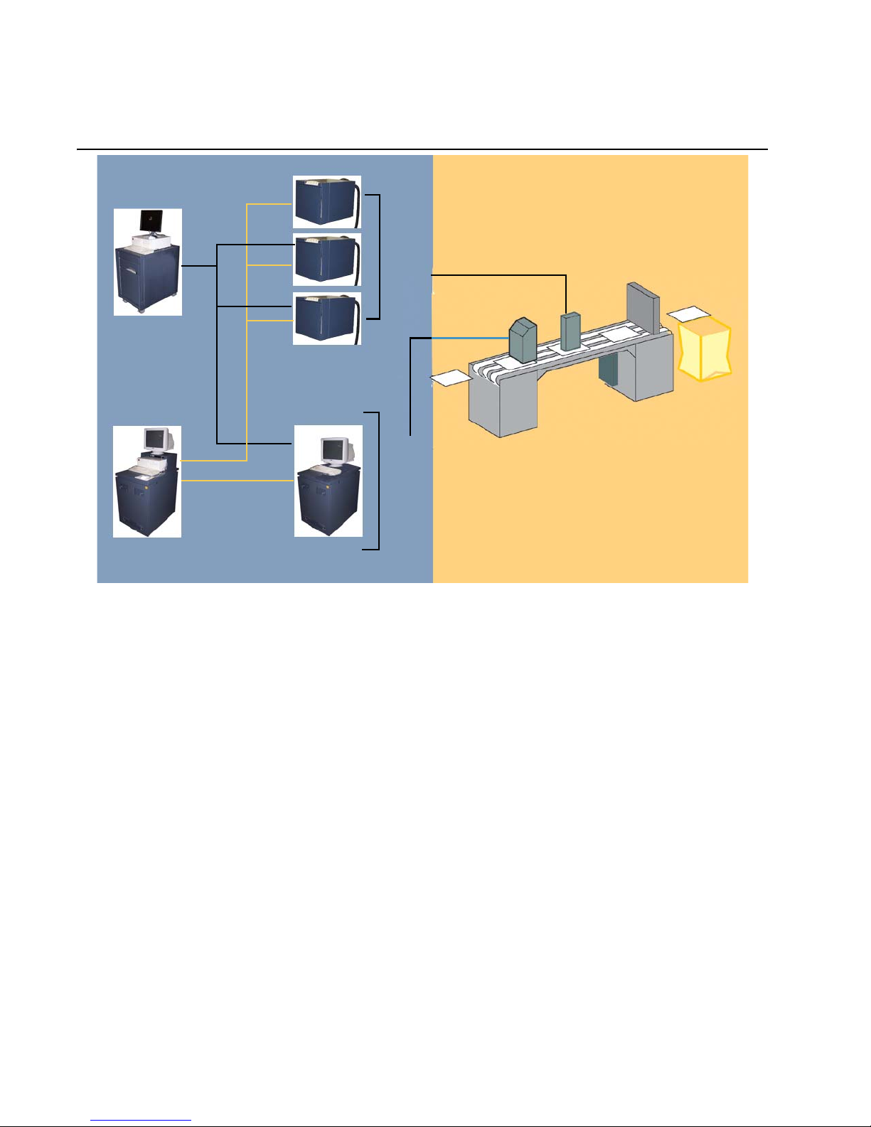
Figure 1.1 shows the different DS5600 series configurations.
Figure 1.1 DS5600 printing system configuration
Note: The term DH6240 is used for the 4.27" printhead in some system
Other system components such as the paper transport, cue sensor, tach
encoder, finishing equipment, and printhead mount(s) are dependent on
the specific combination installed.
The DS5600 series printing systems are identified as:
• Kodak Versamark DP5630 Printing System
Narrow-format printers and one or two DP5600 series print stations
with DH5300 Printheads
• Kodak Versamark DP5640 Printing System
Narrow-format printers and one or two DP5600 series print stations
with DH6240 Printheads
• Kodak Versamark DP5650 Printing System
Narrow-format printers and one or two DP5600 series print stations
with DH6300 Printheads
All configurations are compatible with the current model of the 38.5"
non-stitch printhead mount.
The specific installation and application requirement s determin e the other
system components required. This guide provides operating instructions
for a system with either narrow-format or wide-format printheads.
configurations, but that term is not used in this guide.
12 DS5600 Series Printing Systems
Page 13
DS5600 Components
Printhead
DT3 print station cabinet
CS150 System Controller
Umbilical
Network hub
PC shelf
Monitor
Chapter 1. Overview
DS5600 Components
The DS5600 series has the following standard components:
• Kodak Versamark CS150 System Controller
• Network hub
• One printer or print station
• Printhead
• Umbilical
• Fluid containers
The system can include the following additional components:
• System enclosure (same used for the Kodak Versamark DS5000
Series Printing Systems)
• Computer mounting shelf (used only on a Kodak Versamark DT3 Print
Station)
• Second, third, or fourth narrow-format printer
• Second DT3 print station.
Each printer or print station supports on e printhead. Each printhead print s
one color. Spot color printing is supported using multiple printheads.
Printheads cannot be stitched.
System Controller
When the system does not include a DP5000 series printer (also called a
narrow-format printer), the CS150 is mounted on a DT3 print station.
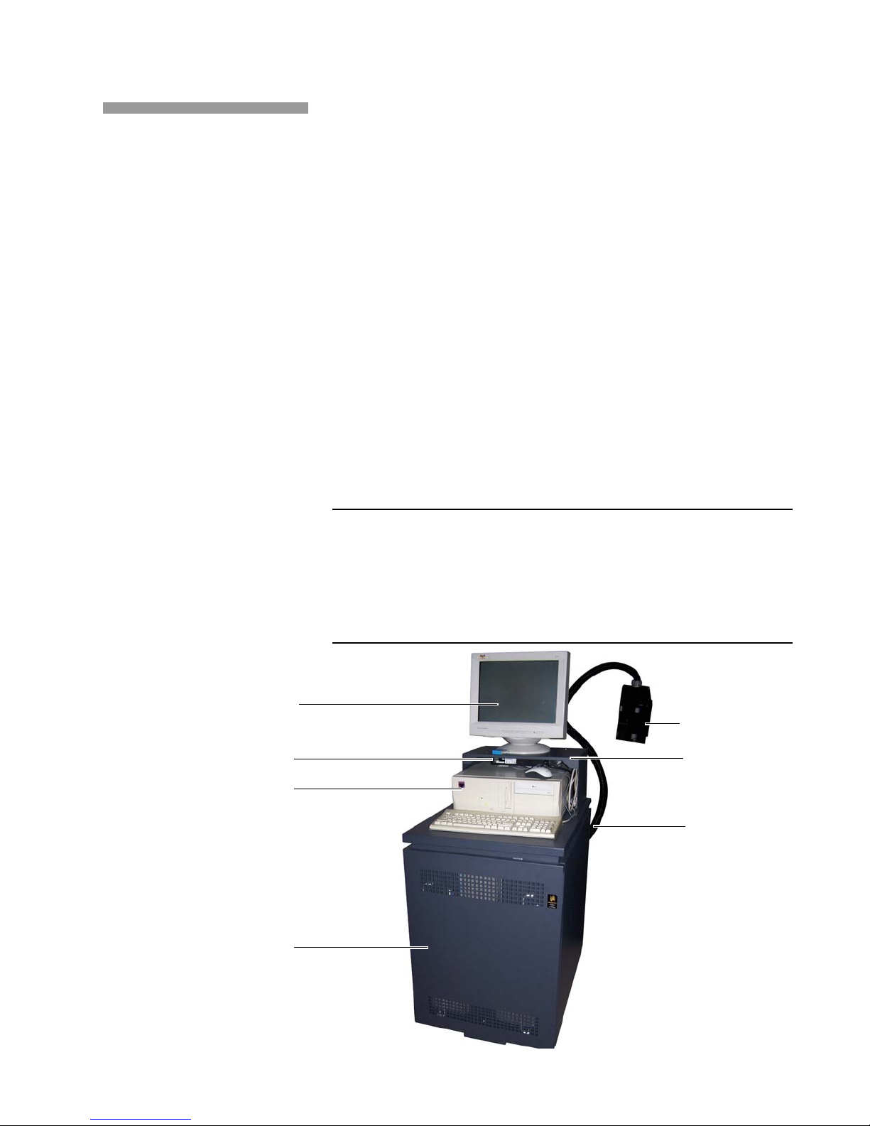
Figure 1.2 shows the system components of a system that does not ha ve
a narrow-format printer.
Figure 1.2 DS5600 components, single DT3 system
Operator Guide 13
Page 14
Chapter 1. Overview
Fluid cabinet
Monitor
Umbilical
Keyboard
Data Main Board
Printhead
DS5600 Components
Figure 1.3 DT3 Print Station
Print Stations
The Kodak Ve rs am ar k DP5600 Print Station is a new component used
only in the DS5600 Series Printing Systems.
The DP5600 consists of a fluid controller for the printhead (DH5300,
DH6240, or DH6300) and an operator terminal for the print station
controller software. When the CS150 is mounted on a Kodak Versamark
DT2 cabinet, the same computer serves as the operator term inal for bo th
the CS150 and the print station using a KVM (keyboard/video/monitor)
switch.
The DT3 cabinet (Figure 1.3) contains the entire fluid system for the
printhead, an internal fluid controller PC, and the Compact DS Main
Board with associated cables. The PC in the DT2 cabinet controls fluidic
and electronic operation of the print station and umbilical. The Compact
DS Main Board relays processes data received over the Etherne t from the
CS150 and transmits rasterized, fiberoptic image data to the printhead.
14 DS5600 Series Printing Systems
Page 15
Chapter 1. Overview
DS5600 Components
Printheads
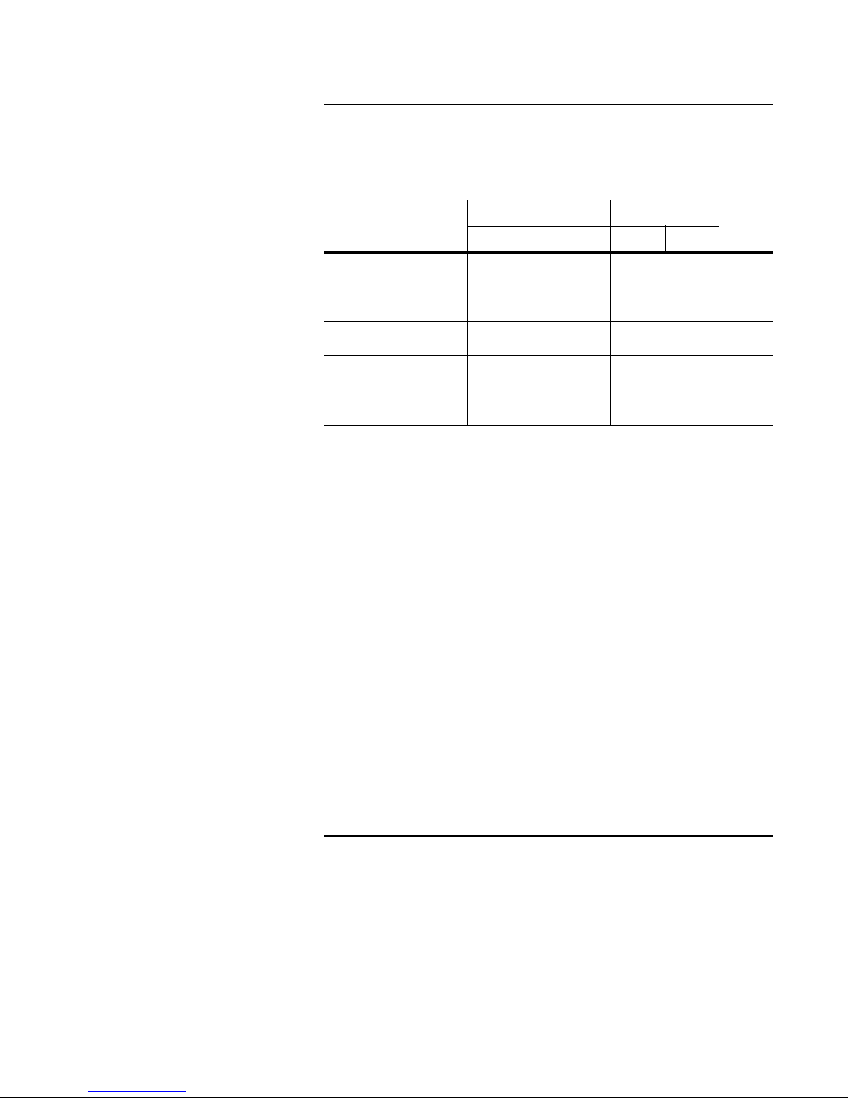
The printheads used in the DS5600 series have the performance
characteristics listed in Table 1.1.
Table 1.1 Printhead performance
Model
DH5340 1 inch 1.06 inch
DH5222 2 inch 2.13 inch
DH5300 4 inch 2.77 inch 300
DH6300 4 inch 3.41 inch
DH6240 4 inch 4.27 inch
Print width Resolution (dpi)
Nominal Exact X axis Y axis
240
(2.69 cm)
(5.41 cm)
(8.66cm)
(10.85cm)
240xx
120
120xx
300xx
300 x 600 500
240 x 240 500
240
480
120
240
300
600
Speed
(fpm)
500
500
500
Resolution is measured in dots-per-inch (dpi) along the print array for the
X axis and in the direction of substrate movement for the Y axis.
Maximum speed in feet-per-minute (fpm) was determined printing a 4-line
address with a 1-line Postnet barcode separated by 0.5-inch. Data
prepared in IJPDS format can be printed faster, but the actual speed at
which a given job can be printed is determined by the interaction of the
image data and the inter-document spacing. Simulated imaging can be
used to test the speed at which a job can be run.
For DS5600 operation, apply the following guidelines to printhead
mounting:
• Maximum height = 6 ft (183 cm) above the base of the printer cabinet.
• Minimum height = 2 ft (61 cm) below the base.
• For narrow-format printheads, the print array should be no more than
0.5 inch (1.27 cm) above the transport belt. Optimum pr int quality is
obtained with a printhead height of 0.125 inch (0.317 cm).
• For the DH5300 and DH6300 (wide format) printheads, the maximum
height is 0.1 inch above the transport belt.
• For the DH6240 printhead, the maximum height is 0.125 inch above
the transport belt.
Fluid Containers
The system requires external fluid cont ainers for ink and replenisher fluid.
These containers can be any combination of the following types:
• 5.2 gallon (20 L) cubitainer
• 55 gallon (209 L) drum
• 275 gallon (1045 L) tote
Operator Guide 15
Page 16

Chapter 1. Overview
CS160
Data
source
Data
station
Fluid
cabinet
Printhead
Controls and status
NIC3
Bit-mapped
data
Controls
and status
Umbilical
Fiberoptic
Print Station
System Operation
System Operation
The print station software monitors the level of ink stored in the in ternal
tank, which is automatically filled from the external supply as ink is used.
Replacing the external supplies can occur without stopping a job. You
must monitor the fluid supplies using the print station software and
replace the external ink or replenisher containe r when alerted by a “check
external fluid containers” message.
The DS5600 series printing system uses data in the Native Input
Command Version 3 (NIC3) format for narrow-format printers (a system
with only DH6240 printheads can use IJPDS format data). The controller
processes job data and sends image data to the printers and print
stations over an RJ-45 Ethernet connection (Figure 1.4). This connection
uses a network hub mounted behind the CS150 computer.
The CS150 uses setup commands embed de d in the NIC 3 da ta to
automatically set job parameters. Alternatively, you can enter job setup
instructions at the CS150 operator terminal.
Figure 1.4 Typical ink-jet printing system
16 DS5600 Series Printing Systems
The job parameters and setup at the CS150 are applied to the data to
determine which part of the bit-mapped data goes to each printhead.
Embedded setup allows jobs to be run without any image positioning at
the controller, however, the CS150 software can be used to correct the
setup or make changes to it if needed.
In a DS5600 system, narrow-format printers operate with the CS150 just
like they do in a DS5000 series printing system. The presence of one or
two DT3 print stations does not change that relationship. The DT3 print
stations operate with the CS150 in the following manner:
• The CS150 serves the function of a Kodak Ve rs am ar k CS220 System
Controller Software or Kodak Versamark CS400 System Controller
Software in a wide-format printing system such as the DS6240.
• The Compact DS Main Board in the DT3 functions as the Kodak
Ve rs am ar k CD120 Data Station or Kodak Ve rs am ar k CD130 Data
Station in a wide-format printing system.
• The DT3 print station software operates norma lly, monitoring all
aspects of fluid controller operation.
Operating procedures and controls are described in Chapter 2,
“Operation.”
Page 17

Chapter 2. Operation
Operation of a Kodak Versamark DS5600 Series Printing System consists
of the following procedures:
• System Preparation
• Startup Procedures
• Controller Operation
• Print Station Operation
The Kodak Versamark CS150 System Controller Software is used to
control the system. The CS150 can be used to control the fluid systems
and data systems of narrow-format printers, but not Kodak Versamark
DP5600 Series Print S tatio ns. When a DP5600 print station is co nfigured,
the Fluid Controller Software that runs on the computer in the DP5600
print station must be used to control that fluid system and printhead.
Note: If two DP5600 print stations are configured, each one must be operated
using its own operator terminal. The first DP5600 shares the operator
terminal of the CS150, but the second DP5600 has a separate operator
terminal.
The primary reference for all CS150 software procedures is the online
Help (see “System Preparation”).
Note: Systems ship with the current version of CS150 System Controller
software (Version 4.0.2.0 as of publication of this guide). Systems with
earlier versions of the software, including all versions called Kodak Versa-
mark Mailscape Software, may not be compatible with the DS5600 series
printing systems. Contact technical support for information on software
upgrades.
Operator Guide 17
Page 18

Chapter 2. Operation
Help button
System Preparation
System Preparation
Before the system can print, the following CS150 software procedures
must be completed:
• Set up production printers
• Configure databases
• Create print layouts
All these procedures are described in the CS150 on line Help. Access th is
information from any screen by selecting the Help button (shown below
on the production “Dashboard” screen). Open specific Help topics by
clicking on items in interactive lists or on the pull-down menus.
18 DS5600 Series Printing Systems
The final procedure in this sequence is production (see “Print Jobs”). All
production printers must be configured as devices in the CS150 sof tware,
and each database to be used as a print source must be configured for
printing.
This configuration, which includes field and record definition as well as
print layout, is saved in a configuration file (*. bcf).
When the printers and databases are configured, a print job is started by
selecting a printer and loading a configuration file (*. bcf).
An optional CS150 module called Read and Image allows a CS150 user
with a camera system (or barcode reader , magnetic strip reader , or optical
character reader [OCR] and a production printing system) to personalize
print products based on a customer number. For convenience, this Help
refers to a camera system when discussing the Read and Image
capability.
Page 19

Startup Procedures
Monitor power
Data from controller
Data out to printer
PC power
KVM for CS150
Data from customer network
CS150 software key
KVM for DT3
KVM switch input
KVM switch
Data output
Chapter 2. Operation
Startup Procedures
The CS150 System Controller is primarily used with the Kodak Versamark
D-Series Printing Systems for applications that require bar coding,
numbering, addressing, and personalizing. The CS150 can oper ate u p to
four printheads in various combinations (See “DS5600 Configur ations” on
page1 1). The featur e key for the CS150 sof tware must match the num ber
and type of printheads being used.
Narrow-format printers should be powered-up normally before the
controller is started. For a system a with DS5000 series enclosur e, startup
is done exactly the same as described in the Kodak Versamark CS150
System Controller Software Getting Started Guide. Review the following
procedures before starting the system initially:
• System Connections
• Startup Sequence
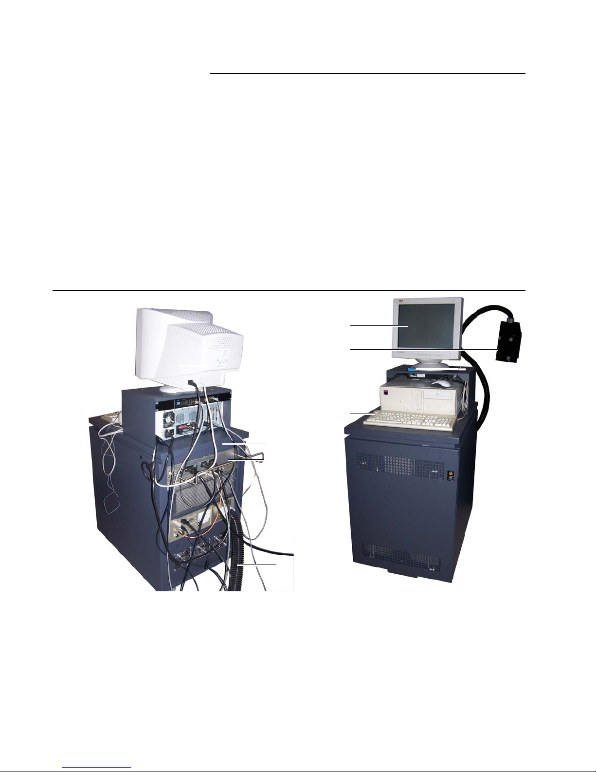
System Connections
For a system without a DS5000 series enclosure, check all the
connections to the controller mounted under the shelf on the DT3 cab inet
(Figure 2.1).
Figure 2.1 Connections, CS150 controller on DT3 cabinet
Operator Guide 19
Page 20

Chapter 2. Operation
Single Data input from controller
Up to four data outputs
DT3 cabinet power
DT3 input power,
PC and monitor power
CS150 power
Startup Procedures
The DS5600 series controller on the DT3 cabinet requires the following
connections:
• Input power
•Monitor
• Keyboard
•Mouse
• Feature key (see note below)
• Data source
One input from the customer data source is r equired. The data source
is typically a LAN or network drive.
• Network hub data connections
Each printer or print station must have an output cable from the
24-port Ethernet switch installed in the system enclosure or the DT3
shelf (Figure 1.2). Input to the hub is a connection to the system
controller. Hub con nections are done at inst allation an d should not be
changed unless a printer is added to the system or permanently
removed. A connected printer does not have to be used. Only printers
active in the current software configuration print.
Note: The CS150 software key (also called a “feature key”) is programmed for
the number of printheads and optional software features of the system. If
a feature is not active that is required, contact technical support.
Startup Sequence
Start the system using this sequence (Figure 2.1 and Figure 2.2):
• Power up the print station(s)
• Power up the narrow-format printer(s)
• Power up the network hub
• Power up the controller PC
Figure 2.2 Network hub and power connections, DT3 print station
20 DS5600 Series Printing Systems
Page 21

Controller Operation
Chapter 2. Operation
Controller Operation
When the controller powers up, the CS150 soft ware main screen appears
(Figure 2.3).
Figure 2.3 Main screen, CS150 software
This section gives an overview of the software and five basic operating
procedures:
• Menus and Screens (overview)
• Device Configuration
• Database Configuration
• Job Selection
• Job Printing
Operator Guide 21
Page 22

Chapter 2. Operation
Controller Operation
Menus and Screens
Operation of the system from the CS150 is done using selections under
the following main menu buttons:
The selections have the following functions:
Production
Used to select the files needed to print a job and do all other basic
operating procedures.
Configurator
Used to configure a new printer or print station.
Diagnostics
Opens the Diagnostics window (Figure 2.4) that is used primarily for
service procedures, but can be used to check the status of narrowformat printers fluid and data systems.
Figure 2.4 Diagnostics window
Note: The Diagnose selection on the main menu runs tests that check the
22 DS5600 Series Printing Systems
status of all devices (printers and print stations) connected to the CS150.
If a device is not communicating for any reason, it will show an error. A
device that is powered off will not communicate. This screen is also used
to remove a device from the setup (Figure 2.5). Consult a service technician before changing the system configuration or running diagnostics.
Figure 2.5 Devices menu, Diagnostics screen
Exit
Closes the CS150 software.
About
Provides the version number of the CS150 software.
Page 23

Chapter 2. Operation
Help
Accesses online help. See “Using Online Help” on page30.
Clear messages
Removes any active messages.
NL
Changes the text to Dutch.
US
Changes the text to English.
DE
Changes the text to German.
FR
Changes the text to French.
ES
Changes the text to Spanish.
IT
Changes the text to Italian.
Controller Operation
CZ
Changes the text to Czechoslavakian.
ZH
Changes the text to traditional Chinese.
Note: The correct optional components for the Microsoft Windows XP Profes-
sional operating system and the correct fonts must be installed on the
controller PC for this function to work correctly.
When the system is powered up, operation consists of the following
procedures:
• Device Configuration
• Database Configuration
• Job Selection
• Job Printing
• Using Online Help
The 'Getting Started Tutorial’ explains these procedures in detail.
Operator Guide 23
Page 24

Chapter 2. Operation
Unknown
Controller Operation
Device Configuration
To print, each printer must be configured in the CS150 software. Use the
following procedure to assign each printer to a service and configure that
printer for use by the system:
1. In the Dashboard window, select Diagnostics. The Diagnostics
window appears.
2. Select Services New Service (or press C
TRL + INSERT) to create a
service view for each printer or print station connected to the
controller. An Unknown device icon appears (see example at left) and
the Select Service dialog appears (Figure 2.6).
Figure 2.6 Select service setup window, CS150 software
3. Select Kodak Service and click OK. The Service Dialog appears.
Note: The address selected must be set using DIP switches on the Compact DS
24 DS5600 Series Printing Systems
4. Select the correct IP address for the device from the drop-down
menu and then click OK.
Main Board in the printer or print station, and two d evices cannot have the
same address. If the address does not match the hardware setting, the
warning “this device is not connected” appears when the device icon is
selected. Contact your supervisor or a service technician if a device
address needs to be changed. When the new device connects, select it
by double-clicking the New Device icon in the list under Services. A
dialog appears asking you to name the new device.
Page 25

Chapter 2. Operation
Controller Operation
5. Enter an appropriate device name and click OK (the example screen
below shows a DP5640 on port 192.168.200.32 named
5640-32
).
6. Repeat the configuration steps for each device in the system.
7. Select File Export System Information (or press C
TRL + S) and
create a new system information file (*.bwi) or save the existing file.
8. If adding a device changes any customer information, select Settings
Customer Info and make the necessary changes.
9. Exit Diagnostics.
10. See the online Help for more information on job and printer setup.
Database Configuration
Use the following procedure to set up a print data source:
1. In the Dashboard window, click the Configurator button. The
Configurator window appears.
2. Select File, then New to start the database wizard. Wizard pages 1
through 4, Database selection, appear.
3. From the scroll-able Database t yp e list, select the version of DBASE
that was used to create the database you will be configuring.
4. Click Browse.
5. In the open dialog, locate and select the DBASE file you want.
6. Click the Open button.
7. Back in wizard page 1 of 4, click Next. Wizard page 2 of 4, Table
selection, appears.
8. Select the desired database table form the t able name drop-down list,
then click Next. Wizard page 3 and 4, Layout config, appears.
Operator Guide 25
Page 26

Chapter 2. Operation
Controller Operation
9. You can view a database record by entering its relative number in the
Current record number box. You can also specify the code page
you want to be used for fields of type “string.” Finally , you may be able
to select a database Index. When you are ready, click Next.
10. You can use the Extra Fields window to define postal code fields to
be used in your print layout. When you are finished defining postal
codes (or if you do not want to define any postal codes), then click
Next. Wizard page 4 of 4, Overview, appears. (Note: you can
observe the results of the code page settings in the Overview page).
11. In the Overview page, you can browse through the da tabase
contents. When you are ready, click Finish. The database you have
just configured appears in the Database window, a secondary
window of the Configurator window.
12. Test the database either by selecting Edit and then Test database or
by clicking the Toolbar button. For more information, see the graph in
the online Help topic for data configuration.
Job Selection
Use the following procedure to specify which job is printed:
1. Selecting Production allows you to go into the Configuration
window and select a print job (Figure 2.7)
Figure 2.7 Print job selection window
2. In the Production window, open the database you want to use
(Figure 2.8).
Figure 2.8 Database window
26 DS5600 Series Printing Systems
3. With a job and database selected, select a printer on the left side of
the Production window (highlight and double click).
Page 27

Chapter 2. Operation
Controller Operation
4. To create a new job setup, or change the setup to add necessary
fields to the labels, drag the selected fields from the Field List and
place them in the template (Figure 2.9).
Figure 2.9 Configuring New Fields
5. When the setup is complete, the job is ready to run. Continue with
“Job Printing.”
Job Printing
When the required files are ready, complete the following steps to print a
job:
1. In the Dashboard window , ch eck th e job a nd setu p b efor e starting to
print (Figure 2.10). Also check the transport or mailbase to make sure
it is ready to operate.
Figure 2.10 Production window - after set up, CS150
Operator Guide 27
Page 28

Chapter 2. Operation
Controller Operation
The Production window has the following buttons and field groups:
Close
Ends the current activity for running the print job and returns you to
the Dashboard window.
Run
Star ts prin ting a job. If necessary, any printers requ ired are brought to
ready before printing begins. When printing is ready, the Run window
shows printing status in real time as the job runs.
Database status
Identifies the current database file for running the print job and
displays the print status of each record.
• A check indicates a record that has printed. You can use the check at
the top right to change the status of selected records.
• A flag indicates a record that has not printed yet. You can use the
check at the top right to change the status of selected records.
• An x indicates a record that has an error. You can use the check at
the top right to change the status of selected records.
Production mode
Allows you to select either of two modes for printing.
• Normal is used to print a job from the beginning or a midpoint.
• Remake is used to print a job’s error records after you’ve corrected
them. Check with the production supervisor for restrictions or special
procedures for reprinting documents.
Range
Allows you to select the records to be printed within a range of record
numbers. After entering a new number for the beginning or ending
record, or for both, you must select Change before the new numbers
can be used for printing.
Counters
Displays the numbers of records selected for printing (in gray),
already printed (in green), and unable to be printed (in red).
28 DS5600 Series Printing Systems
Search...
Allows you to search for text in the database. Online Help provides
more detail on the ability to control the search.
Page 29

Chapter 2. Operation
Controller Operation
Export results
Allows you to create a file that lists the records that are selected for
printing, already printed, or unable to be printed, or any combination
of these statuses. The file does not indicate more than the record
numbers.
Select Fields...
Allows you to control which database fields are displayed in the
Dashboard window.
Product counter
Allows you to set the number for the counter of the records printed from
the job.
See “Menus and Screens” on page22 for descriptions of the remaining
controls.
For additional information on job printing, see the “Getting Started
Tutorial” and the Help topic “Printing a job” in the CS150 online Help. For
reference, see also:
• CS150 Getting Started Guide
• Kodak Versamark Font Tools Getting Started
2. Click on Run to print the job. The Run window appears and the job
begins to print.
Figure 2.11 Run window, CS150
Operator Guide 29
Page 30

Chapter 2. Operation
Run
Production
Dashboard
Help button
Field 1.
Field 2.
Field 3.
Display button
Controller Operation
Using Online Help
Online Help is available from any window (see the example windows
below). Use the following steps to access the online Help:
1. Select Help in the lower right corner of the work area.
2. Select the Find tab.
3. Enter a search term in Field 1. A list of matching terms appears in
Field 2 and a list of topics in Field 3.
4. Select the best match from the list of topics in Field 3, or select a term
in Field 2 to narrow the search.
Use the arrows to scroll through the lists in Field 2 and Field 3. Click
an item in either list to highlight it.
5. Select Display to view the highlighted topic in the Field 3 list, or
select Cancel to end the search.
30 DS5600 Series Printing Systems
Page 31

Print Station Operation
Fluid Controller Software
Release 5.xxx
Serial Number: xxxx
Press any key
(C) Copyright
Eastman Kodak Company
1995-2007, All rights reserved
Chapter 2. Operation
Print Station Operation
The CS150 cannot control or display status information about a Kodak
Ve rs am ar k DT3 Print Station or wide-format printhead (Kodak Versamark
DH5300, Kodak Versamark DH6240 or Kodak Versamark DH6300). The
DT3 must be controlled using its operator terminal. One DT3 operator
terminal can share the PC used by the CS150, but the second DT3 has its
own separate PC. Operator procedures are the sam e regardless of which
PC is used. This section describes these procedures.
Keyboard Controls
The keyboard is the primary interface to the DT3 print station software.
The following commands can be entered using the keyboard:
• On a PC shared with the CS150 software, please press: S
L
OCK, SCROLL LOCK, UP ARROW to switch to the DT3 operator
terminal display.
• Press C
printhead).
• Press
Caution: Pressing
up the print station.
• Press
Pressing
containing the message:
• Press F8 to clear any error that tempora rily pr ev en ts printin g .
Pressing
present has no effect on print station operation
• Press F10 to display information about the hours of op e ra tio n for the
print station and printhead, the versions of software inst alled, an d the
type of ink in use.
• Press E
menu or screen. Pressing E
• Press any key to progress past the initial screen displayed by the DT3
print station software (Figure 2.12). The next screen displayed is the
Control Menu used for all operator procedures (see the next
section).
Figure 2.12 Fluid controller software title screen
CROLL,
TRL + Z to place printhead in standby mode (ink circulating to
F1 to see Help information for any screen or menu.
F1 after entering standby mo de through pressing CTRL + Z locks
F2 for an explanation of a displayed error.
F2 when no error is present results in a dialog box
There are no pending errors
F8 when no error is present or when a continuous error is
.
SC to leave the information screen and return to the previous
SC also clears any temporary errors.
.
Operator Guide 31
Page 32

Chapter 2. Operation
CONTROL MENU
SERVICE MENU
PARAMETERS MENU
Quit
SETUP MENU
Print Station Operation
Screen Displays
The DT3 print station software displays menu screens and status
screens. The following sections describe these two types of displays.
Menu Screens
The DT3 print station software has a simple menu tree made up of four
menu screens (Figure 2.13).
Figure 2.13 Menu tree, DT3 print station software
Note: On any menu, selecting an item without a description has no effect. No
32 DS5600 Series Printing Systems
The four menus are used to access screens for all procedures. The
following sections describe the functions on these menus used for
operation. Screens used for service procedures are described only in
relation to operation.
On all four menus, an item can be selected in either of the fo llowing ways:
• Type (press) the menu item number.
• Use an Arrow key to highlight the item and then press Enter.
description appears as “--------”, a row of dashes or hyphens.
Page 33

Chapter 2. Operation
TITLE SECTION
STATUS AND MEASUREMENT SECTION
EYELID STATUS FUNCTION/STATUS TIME REMAINING
STATE NUMBER
HS SYSTEM STATUS COLUMN MEASUREMENT COLUMN MESSAGE COLUMN
Print Station # 1
Remote Eyelid PRINTHEAD READY Time: complete
Press ESC to return to previous MENU State # 16
SYSTEM STATUS MEASUREMENTS MESSAGES
Fluid Servo ON 14.99 PSI
Vacuum Servo ON 10.0 In. Hg.
Printhead (S1000) 12345 Serial No.
Stim. Drive ON 0.299 Tab Vrms
Chg. Plt.Heater ON Ready to Print
PntHd Ink/Amb. Temp. 29./27. Deg. C
Charge Voltage ON (130.7 Volts)
Ink Concentration OK
Ink Level OK Off Line
Printhead Use 207.5 Hours Exit Save
Print Station Use 1234 Hours
Print Station Operation
Status Screens
Status screens display when you select a function listed on the Control
Menu or Service Menu.
Status scr eens display information only; n o control functions are available
on a status screen. Help information is available on any st atus screen
(press
Figure 2.14 Status screen layout
F1). Figure 2.14 shows the status screen format.
Figure 2.15 shows an example status screen (Printhead Ready reached
from the Control Menu.)
Figure 2.15 Printhead Read y status screen
Operator Guide 33
Page 34

Chapter 2. Operation
Print Station Operation
During operation, the following status displays should be monitored:
Eyelid Status
Shows data station or print station eyelid control. Remote Eyelid is
data station control and Local is print station control.
Function Status
Displays the function name. When the display flashes, the function is
active; otherwise the function is not runnin g or has bee n comp le ted .
Time Remaining
Displays a countdown (in seconds) until the function is complete.
State Number
Displays which state is active. All states are numbered. The number
changes to indicate the state.
Table 2.1 lists all status information displayed on the various screens.
Table 2.1 System status display summary
Parameter/Component Possible Statuses Range in Ready Description
Fluid servo On 14.00 to 16.00 psi Pressure values below 14 ps i occur during
bringup or shutdown.
Vacuum servo On
On hold
Printhead (speed)
Link down
9.9 to 14.0 in. Hg Values above 14 in. Hg occur during clean
or shutdown.
Printhead serial
number
Indicates whether the print station can
communicate with the printhead.
Link error
Stim drive On
Unlocked
0.200 to 0.700 V
Unlocked indicates a printhead
RMS
malfunction. Values above 0.4 are normal
during clean or bringup. Will go as high as
1.5 V
during a sonic cleaning cycle.
RMS
Charge plate heater On - Status of the heater that prevents ink
condensation.
Printhead ink/
ambient temperature
Charge voltage On
- 15 to 45 C Ink's temperature and the air temperature
in the printhead.
50.0 to 150.0VDC Voltage on the charge plate.
Low
Ink concentration
Ink level OK
OK
Low
High
Low
Empty
Not applicable Darkness of the ink. Replenisher is added
as necessary. A constant low or high state
may indicate a problem.
Not applicable Amount of ink in the ink tank. Ink is added
as necessary. A constant empty, filling, or
high state may indicate a problem.
1
Filling
High
Printhead use - 0 to 65000 h Accumulated hours the printhead has
operated.
Print station use - 0 to 65000 h Accumulated hours the print station has
operated.
1. OK displayed as light blue text = ink drawn from the external ink supply at the next fill. OK in dark blue = ink drawn from the external
replenisher supply at the next fill.
2. If INSTALL is used when updating software, the accumulated hours will be reset to 0 (zero). Use UPDATE to preserve the hour
record.
2
34 DS5600 Series Printing Systems
Page 35

Chapter 2. Operation
** CONTROL MENU **
Function Selections
1 Ready
2 Clean
3 Shut down
4 Clean - long
5 ---------6 Adjust
7 Remote/Line
8 Service menu
9Quit
Choose a function, enter the number
Press F1/F2 key for HELP.
PARAMETER ADJUSTMENTS
Press PgDn or PgUp to select.
Press
or keys to change values.
Press ESC to EXIT.
STIM. PHASE adjustment (0 to 15 units) : 9
CHARGE VOLTAGE adjustment (+-10 volts) : 120.1
INK PRESSURE adjustment (+- 1.0 psi) : 15.00
Remote/Service SelectionS
Press PgDn or PgUp to select.
Press
or keys to change values.
Press ESC to EXIT.
[X] Remote eyelid, Data/Print Station control of eyelid.
[ ] Local eyelid, Print Station control of eyelid.
[X] On line, send “Ready to Print” only when ready.
[ ] Off line, send “Ready to Print” all the time.
Print Station Operation
Control Menu Procedures
Use the Control Menu (Figure 2.16) to access the primary screens used
for operation and to access the other menus.
Figure 2.16 Control Menu, DT3 print station software
Use Adust (6) to adjust print quality. See the documentation shipped with
the printhead for information on identifying defects.
Figure 2.17 Parameters Adjustments screen, Control Menu
Use Remote/Line (7) to set how the system controls the DT3 and its
printhead.
Figure 2.18 Remote/Service Selection screen, Control Menu
Operator Guide 35
Page 36

Chapter 2. Operation
Print Station Operation
Table 2.2 summarizes all the Control Menu selections and procedures.
Caution: A Shutdown MUST be done before quitting , or an ink spill at the pr inthead
can occur.
Table 2.2 Control menu functions
Function Use
1 Ready Brings the printhead to normal operational condition. Selecting this function displays the
Printhead Ready status screen. When the printhead is ready for normal operation, the
Printhead Ready Cycle status screen displays.
2 Clean Starts a 1-minute printhead clean cycle without sonic stimulation. Typically, this function
is used to clean the printhead after a short shutdown (up to a few hours) or when
removing the eyelid/ installing the ca tchpan to perform printhead servicing. Selecting this
function displays the Printhead Clean status screen.
3 Shut down Starts a 15-minute shut down cycle to remove all fluid from the printhead. Typically this
function is used to shut down the printhead at the end of the day or anytime after ink
circulation in the printhead has occurred and the quit function will be selected. Selecting
this function displays the Shutdown Printhead status screen.
4 Clean - long Starts a 5-minute printhead clean cycle without sonic stimulation. Typically, this function
is used the clean the printhead after an overnight shutdown. Selecting this function
displays the Long Clean status screen.
5 ---------
No function.
6 Adjust Used to change the stimulation phase, charge voltage, and ink pressure settings.
Selecting this function displays the Parameter Adjustments screen (Figure 2.17) used
to change settings and improve printhead performance.
• Stim phase can be changed in 1 segment increments (maximum change of 15
segments possible)
• Charge voltage can be changed in 0.4 VDC increments (maximum change of ± 10
VDC possible within operating range set by supervisor)
• Ink pressure can be changed in 0.07 PSI increments (maximum change of ± 1 PSI
possible)
7 Remote/Line Used to determine whether the print station or the data station controls when the eyelid
opens and closes, or to allow printing by other print stations installed in printing system
when the print station is inactive. The data station normally controls the eyelid when
running a job. Selecting this item displays the Remote/Service screen (Figure 2.18).
• Remote eyelid - data station controls the printhead eyelid positioning. Used for
normal print operations
• Local eyelid - print station controls the printhead eyelid position. Used for pr inthead
cleaning and maintenance
• On-Line - print station printing is controlled by data station
• Off-line - print station will not print, but other print stations in system can print
8 Service menu Used to access simple maintenance functions. Selecting this function displays the
Service Menu screen.
9 Quit Used to exit the print station software.
36 DS5600 Series Printing Systems
Page 37

Chapter 2. Operation
** SERVICE MENU **
Function Selections
1 Ready - steps
2 Clean - service
3 Shut down
4 Vacuum/ink fill
5 -------6 Clean - install
7 Sequence summary
8 Control menu
9 Parameters menu
Choose a function, enter the number
Press F1/F2 key for HELP.
Print Station Operation
Service Menu Procedures
Use the Service Menu (Figure 2.19) to access functions used for
operator maintenance procedures. Check with a service technician before
starting these procedures. Some service procedures require specific
information about the system, for example: when using a standard ink
there are 15 steps in the Ready - Steps function, but with a special ink,
there could be more steps.
Figure 2.19 Service Menu, DT3 print station software
Table 2.3 summarizes the procedures done using the selections on the
Service Menu.
Table 2.3 Service menu function
Item Description
1 Ready - steps Brings the printhead to Ready under direct operator control. The print station
progresses through states 1-12. However, to progress to states 13, 14, and 15, you
must press the S
PACEBAR to advance to ready. Typically used to looks at jets when
trying to determine print quality issues. Selecting this function displays the Step To
Ready status screen.
NOTE1
2 Clean - service Starts a 3-min ute printh ead clean cycle with sonic stimulation . Typically , this function
is used to clear print defects such as streakers, crooked jet s, or char ge short s. Refer
to Chapter 3, “Messages” for symptoms of print problems. Selecting this function
displays the Service Clean status screen.
3 Shut down Shuts down the printhead. Typically used at the end of the day or prior to changing
the printhead or ink in use. Selecting this function displays the Shutdown Printhead
status screen.
4 Vacuum/ink fill Used to fill the print station ink tank. Selecting this item displays the Vacuum/Ink Fill
status screen.
5 ----------- No Function.
6 Clean - install Starts a 10-minute printhead clean cycle with sonic stimulation. Typically, this
function is used to clean a newly installed printhead. It can also be used to clean the
printhead after the print station has been shut down for several days. Selecting this
item displays the Clean - Install status screen.
Operator Guide 37
Page 38

Chapter 2. Operation
** PARAMETERS MENU **
Function Selections
1 Pressure
2 Vacuum
3 Stim. / Stimgram
4 Stim. phase
5 Charge voltage
6 --------7 Standby
8 Service menu
9 Setup menu
Choose a function, enter the number
Press F1/F2 key for HELP.
Print Station Operation
Table 2.3 Service menu function (Continued)
Item Description
7 Sequence
summary
Allows you to review the current values, times, and states for print station valves,
motors, and sensors. Selecting this item displays the Sequence Summary screen.
The following sequences can be selected:
• Ready • Shutdown PH
• Standby • Short Recover
• Install Clean • Vacuum/Ink Fill
• Long Clean • Service Clean
• Fast Ready • Step to Ready
• Fast Recover • Clean
• Ink Too High • Shutdown PH
• Carryover
8 Control menu Used to exit to the Control Menu.
9 Parameters menu Used by supervisors, field engineers or maintenance technicians to perform more
detailed maintenance. The Parameter Menu screen is password protected.
Parameters Menu Procedures
Use the selections on the Parameters Menu (Figure 2.20) to configure
the DT3 print station and printhead.
Figure 2.20 Parameters Menu, DT3 print station software
38 DS5600 Series Printing Systems
These settings are critical to proper operation of the equipment and
should be done at installation. Changes should be made only by a se rvice
technician. This menu is password protected.
Note:Press
F10 to display information about the hours of operation for the
print station and printhead, the versions of soft ware installed, and the type
of ink in use.
If necessary , m ake changes to the followin g parameters after consulting a
service technician or technical support:
• Pressure adjustment
• Vacuum Adjustment
• Stim adjustment
• Stim phase adjustment
• Charge voltage adjustment
Page 39

Chapter 2. Operation
Print Station Operation
The following sections describe how the functions of these parameters.
Pressure Adjustment
This procedure should only be done to match adjacent printhead ink
coverage. Consult a service technician befo re ad just i ng pre ssure.
Caution: Do not change the center point of the pressure by more than 1.5 psi
(10.3 kPa).
Note: You have a range of 1 psi (6.8 kPa) above and below the center point for
a total range of 2.0 psi (13.2 kPa). Changes of more than 0.5 psi (3.4 kPa)
may require changes to the charge voltage and stimulation phase. Printhead operation depends on the correct relationship of pressure, charge
voltage, and stimulation phase.
Use the following procedure to change the center poin t of the operator ink
pressure adjustment range.
1. From the Control Menu screen, select Service Menu (8).
2. Select Parameters Menu (9), and enter the password.
3. Select Pressure (1).
Note: The pressure can be changed for one sequence (S) or all sequences (G).
4. Select (G).
Caution: Do not change the center point of the pressure by more than 1.5 psi.
5. Change the pressure setting by small amounts to find the lowest
pressure setting that prints without light print. If the system uses
multiple print stations, compare the print darkness to an adjacent
printhead's test patterns as well.
Lowest pressure setting: ________ psi.
Note:If possible, avoid changing the pressure mo re than ±1.0 psi fr om the
value entered on the Printhead Information Sheet.
6. Change the pressure setting by small amounts to find the highest
pressure setting that prints without dark print. If the system uses
multiple print stations, compare the print darkness to an adjacent
printhead's test patterns as well.
Highest pressure setting: ________ psi.
7. Calculate the center of the pressure range by subtracting the lower
pressure from the upper pressure. This value is the operator's
pressure range.
V acuum Adjustment
The vacuum adjustment should be done only by a trained service
technician. It is never required as part of normal operation. It is done
during installation and then checked and adjusted if the print station,
printhead, or umbilical is moved.
Operator Guide 39
Page 40

Chapter 2. Operation
Print Station Operation
Stim Adjustment
Stim and stim gram adjustment should be done only by a trained service
technician. It is never required as part of normal operation.
Stim Phase Adjustment
The phase setting may require adjustment when the print station reaches
a maximum operating temperature, or if the operating envir onment
changes significantly. There are 16 phase settings to choose from. Use
the following procedure to find and record the stim phase window:
1. From the Control screen, select Service Menu (8)
2. Select Parameters Menu (9), and enter the password.
3. Select Stim Phase (4).
4. Select each of the 16 different phase settings. Record all phase
settings that print test patterns of good quality.
5. Examine the printed test patterns. Several adjacent settings should
provide good print quality. These phase settings are the phase
window.
6. Find the center of the Phase window, then set the phase one value
above the center. This is the set point.
Charge Voltage Adjustment
Use the following procedure to find and record the charge voltage
window:
1. From the Control Menu screen, select Service Menu (8).
2. Select Parameters Menu (9),and enter the password.
3. Select Charge Voltage (5).
4. Lower the charge voltage to find the lowest charge voltage that will
allow printing without dark defect.
Lowest charge voltage setting: ________ VDC.
5. Raise the charge voltage to find the highest charge voltage that will
allow printing without pickout.
Highest charge voltage setting: ________VDC.
6. Calculate the set point of the charge voltage range.
a. Subtract the lower charge voltage from the upper charge volt age.
This value is the Charge Voltage window.
b. Divide theCharge Voltage window value by 2 and add the result
to the lower charge voltage.
7. Set the center point of the range to this result.
40 DS5600 Series Printing Systems
8. Press E
SC, then select Service Menu (9) and Control Menu (8) to
return to the Control Menu screen.
Page 41

Chapter 2. Operation
** SETUP MENU **
Function Selections
1 PH Height
2 Ink Number
3 Concentration
4 System Language
5 Help Language
6 O.T. Language
7 --------8 Parameters menu
9 ---------
Choose a function, enter the number
Press F1/F2 key for HELP.
Print Station Operation
9. Print test patterns at the expected job speed. Check the results for
pickout and dark defect.
Caution: Do not change the center point of the pressure by more than 1.5 psi
(10.3 kPa).
Note: The range of 10 VDC above and 10 VDC b elow the center point for equal
a total range of 20 VDC. Extreme cases of pickout or dark defect may
need changes of 5 to 10 VDC to correct printhead performance. Small
changes of about 2 VDC can correct minor cases of pickout or dark
defect.
Use the following procedure to change the center point of the operator
charge voltage adjustment range:
1. Divide the pressure range by 2.
2. Add the result to the lower pressure.
3. Set the center point of the range to this result.
4. Press E
SC, then select Service Menu (9) and Control Menu (8) to
return to the Control Menu screen.
5. Print test patterns at the expected job speed. Check the results for
pickout, dark defect, or ghosting.
6. Print test patterns at the expected job speed. Check the results for
ghosting.
Standby
Select Standby to circulate ink through the print station and printhead.
Note: Ink circulation can also be accomplished by pressing C
while the print station is powered up and ready for operation.
Setup Menu Procedures
Use the selections on Setup Menu (Figure 2.21) only after consulting a
service technician or technical support.
Figure 2.21 Setup Menu, DT3 print station software
TRL + Z any time
Operator Guide 41
Page 42

Chapter 2. Operation
Print Station Operation
Use the following selections on the Setup Menu only after consulting a
service technician. These parameters should never require adjustment
during operation.
PH Height
Used to provide the height of the printhead above the base of the
print station. This information is used to set the default levels for the
print station pressure and vacuum parameters.
Ink Number
Used to provide the ink number to the print station. The ink numbe r is
used to set the default concentration value. The print station must be
shutdown before changing this number.
Concentration
Used to set the resistivity of the R-Cell (concentration). Number is
found on the label of the R-Cell.
System Language
Used to select the language the control terminal uses during
operation. Choices include:
• English
•French
• Spanish
•German
• Japanese
• Default
Help Language
Used to select the language the control terminal uses during
operation. The language choices are the same as for system
language.
O.T. Language
Used to select the language the control terminal uses during
operation. The language choices are the same as for system
language.
42 DS5600 Series Printing Systems
Page 43

Chapter 3. Messages
Print Station # 1
Remote Eyelid PRINTHEAD READY Time: complete
Press ESC to return to previous MENU State # 16
SYSTEM STATUS MEASUREMENTS MESSAGES
Fluid Servo ON 6.84 PSI
Vacuum Servo ON 10. In. Hg.
Printhead OK 0006 Serial No.
Stim. Drive ON 0.775 Tab Vrms
Chg. Plt.Heater ON
PntHd Ink/Amb. Temp. 27/25 Deg. C
Charge Voltage ON ( 123 Volts)
Ink Concentration LOW
Ink Level FILLING
Printhead Use 207.5 Hours
Messages
This chapter provides responses to common messages that appear on
the print station operator terminal during operat ion . Fo r a co mp let e list of
print station messages, refer to the print station Service Guide.
The print station software displays active text and messages in higher
intensity or with reversed colors (Figure 3.1).
Figure 3.1 Print station operator terminal screen display
Messages appear on screen displays in bold text or a contrasting color
(Figure 3.2).
Figure 3.2 Display screen with sample messages
Operator Guide 43
Page 44

Chapter 3. Messages
< Print Station Initialization >
Disk Drive check available_bytes
Checking Station Type
Loading Station Data FLUID.TBL
Printhead Communication
Printhead Communication
Printhead Communication
Printhead Communication
Printhead Communication
Loading Ink Data INKTYPE.VAL
Loading Ink Data INKDEX.DAT
Loading Configuration MACHINE.INI
Reading States Table STATESEQ.TBL
Loading Help FLUIDHLP.001
Loading Error Help ERRORHLP.001
Loading O.T. Messages MESSAGE.001
Charge Short Testing
Checking Station Speed
30 seconds Calibration Calibration failed.
Pending error(s). Press any key to continue.
Messages
Message Displays
Message Displays
Errors are displayed in red text on the screen. Errors prevent printing by
taking the print station out of ‘Ready to Print’ status or by preventing it
from being put in that status (the ‘Ready’ selection inactive). Figure 3.3
shows a sample error message displayed during startup.
When any error occurs, press
then press
pressing
F8 to clear the error. Serious errors cannot be cleared by
F8. If such an error occurs, contact your service technician or
F2 to display information about the error,
contact Kodak technical support.
Figure 3.3 Error message during startup
Message List
Check External Containers
Explanation: The ink level has remained incorrect for 5 minutes. Possible cause: 1.
Action: 1. Check th e external supplies of ink and replenisher, and replace if
44 DS5600 Series Printing Systems
Messages are listed in alphabetical order. When more than one cause is
listed, the first is the most likely cause of the message. When more than
one action is given, each action should be taken in numerical order.
empty external supply; 2. tubing from external supplies; 3. external ink or
replenisher supply solenoid; 4. fluid controller board; 5. ink level switch.
necessary.
2. Check the tubing from the external supplies for kinks or breaks.
3. If the error recurs, have a service technician run diagnostics to check
the solenoids and switches.
Page 45

Check Ink Reorder Number
Explanation: The ink was changed recently, and the print station determined that the
Action: 1. Check the ink reorder number.
Ink Concentration HIGH
Explanation: Ink concentration is higher than normal. The print sta tion may not be
Action: 1. Monitor image darkness for at least one hou r to allow the print st ation
Chapter 3. Messages
Message List
difference in concentration was too great to correct by adding ink or
replenisher. Possible cause: 1. software configuration; 2. resistivity
sensor; 3. fluid controller board.
2. If the error recurs, have a service technician reset the ink reorder
number. If the error persists, have a service technician run
diagnostics on the resistivity sensor and fluid controller board.
adding replenisher automatically. High concentration can occur if the
printhead is ready for a long period without printing. Possible cause:
1. low ink use in a job or circulating ink without printing; 2. ink leakage;
3. inline filter (replenisher); 4. fluid controller board.
to automatically correct ink concentration. The problem is corrected
when “Ink Concentration OK” displays.
2. Check the external supply for replenisher, and replace the drum if
necessary.
3. If the error recurs, have a service technician check the inline filter for
replenisher. If the error persists, and printing is too dark, have a
service technician make sure that the proper ink reorder number has
been entered, run diagnostics on the inkjet controller board, and
check that ink is not leaking into the print station from the external
containers.
Ink Concentration LOW
Explanation: Ink concentration is lower than normal. The print station is not
Action: 1. Monitor image darkness for at least one hou r to allow the print st ation
Ink Level FILLING
Explanation: This status message displays when the print station is automatically
Action: None required unless this message displays for more than several
automatically adding ink, or it is adding too much replenisher. Possible
cause: 1. high ink use in a job; 2. replenisher leakage; 3. inline filter (ink);
4. level switches; 5. solenoid valves; 6. fluid controller board.
to automatically correct ink concentration. The problem is corrected
when “Ink Concentration OK” displays. If this message displays for
more than an hour, proceed with the next action.
2. Check the external supply for ink, and replace the drum if necessary.
3. If the error recurs, have a service technician check the inline filter for
ink. If the error persists, and printing is too light, have a service
technician make sure that the proper ink reorder number has been
entered, run diagnostics on the inkjet controller board, check that the
fluid supply lines from the external containers are not blocked, and
that fluid can flow freely to the print station. Next, have the service
technician make sure the level switches in the ink tank are oper a ting
normally and that switch connections are secure. Then check that the
solenoid valves that control fluid flow are operating normally and that
connections are secure.
adding fluids. Possible cause: 1. empty containers; 2. fluid lines; 3. level
switches; 4. solenoid valves
minutes. The problem is corrected when “Ink Level OK” displays.
Operator Guide 45
Page 46

Chapter 3. Messages
Message List
Ink Level LOW
Explanation: Ink level is below normal operating limits. The print station will
automatically add fluids when the operating state allows refilling.
Action: 1. Non e required unless this message displays for more than an hour.
2. If the error recurs, have a service technician check the vacuum pump
No Help Available For This Function
Explanation: There is no online Help for this menu item or screen.
Action: None is required.
The problem is corrected when “Ink Level OK” displays.
for damage.
46 DS5600 Series Printing Systems
Page 47

Daily Maintenance
Chapter 4. Operator Maintenance
This chapter describes routine maintenance procedures that must be
done to ensure that the system continues to operate properly. These
tasks take only a few minutes and do not require any tools.
For Kodak Versamark DH5222 Printheads and Kodak Versamark DH5340
Printheads, the following tasks should be done as needed or every 8
hours of run time, whichever is more frequent.
Printhead Bottom Cover Cleaning
Clean the cover that protects print array on the bottom of the printhead
enclosure by removing the cover and rinsing it off with ordinary tap water
or D.I. water. To remove dried ink, soak the cover in warm water, then
wipe it off. For an illustration of the specific type of cover and its location,
see the document shipped with the printhead.
Printhead Cleaning
Wipe ink, dirt, and paper dust off the exterior of the printhead with a soft,
damp cloth. Mild detergent can be used if needed. Do not spray water or
any cleaning fluid direct on the printhead. Apply water or detergent to the
cloth used to wipe the printhead. Clean the printhead covers under the
following circumstances:
• Before printing, as needed, with POC bypassed or in standby
• When the printhead bottom cover is cleaned
• When visible ink or paper dust accumulates on any part of the covers
• When the printhead is swabbed, or after any other service procedure
Operator Guide 47
Page 48

Chapter 4. Operator Maintenance
Air filter tab
Air filter bracket
Weekly Maintenance
Weekly Maintenance
The following maintenance procedures are required for Kodak Versamark
DS5600 Printing Systems components:
• Printhead air filter replacement
Only the wide-format printheads (Kodak Versamark DH5300, Kodak
Ve rs am ar k DH6240, and Kodak Versamark DH6300) have this filter.
• Cabinet air filter
Both printers and print stations have this filter.
Printhead Air Filter
Inspect the printhead air filter on the wide-format printheads for dirt, paper
dust, ink, or any other debris. If the filter is coated, replace it. Remove the
filter from its bracket by pulling up on the tab (Figure 4.1).
Figure 4.1 Printhead air filter, DH6240
Note: The filter bracket is mounted horiz on tally on the Kodak Versamark DT3
48 DS5600 Series Printing Systems
Cabinet Air Filter
Inspect the cabinet air filter for dirt, paper dust, ink, or any other debris. If
the filter is coated, remove it and clean it with ordinary tap water or D.I.
water and mild detergent. Let the filter air dry. Install a replacement filter
while the cleaned filter dries. If cleaning fails to restore the original
appearance of the filter, replace it.
Print Station (Figure 4.2), but vertically on narrow-format printers. The
removal and cleaning procedure is the same for both filters.
Figure 4.2 Cabinet filter, DT3 print station
Page 49

Page 50

Eastman Kodak Company
3000 Research Boulevard
Dayton, OH 45420 U.S.A.
© Kodak, 2010
TM: Kodak, Versamark
To learn more about solutions from Kodak, visit
graphics.kodak.com.
Subject to technical change without notice.
 Loading...