

Page 1

Magnus VLF With ContinuousLoad
Platesetter
653-00832E-EN Rev A
Internal 732-00027E-EN Rev A
Visual Reference Guide
Original instructions
English
Page 2
1
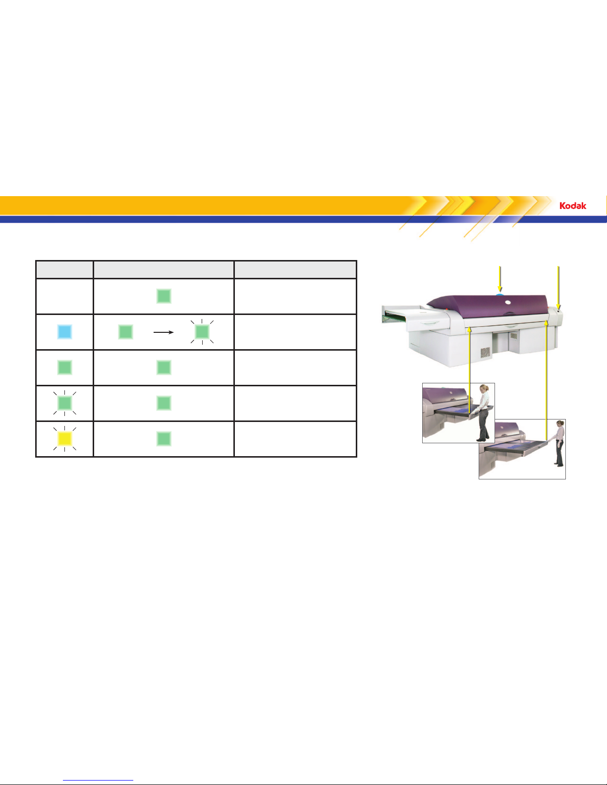
Status light Device ready and start buttons Operator action
O Solid green
The platesetter is ready. Submit a job from the workflow
software when you are ready.
Solid blue
Solid green
Flashing green
Place the plate on the load table. Push the plate in against
the plate stopper and then press a start button or the
Device Ready button.
Solid green Solid green Wait—the platesetter is exposing a plate.
Flashing green Solid green Wait—the platesetter is unloading and ejecting a plate.
Flashing yellow Solid green
An error has occurred and the job is suspended. Follow
the instructions on the Messages tab in the Kodak® Print
Console software.
Operational lights and what they mean
Status light
Device Ready button
Start buttons
Page 3
2
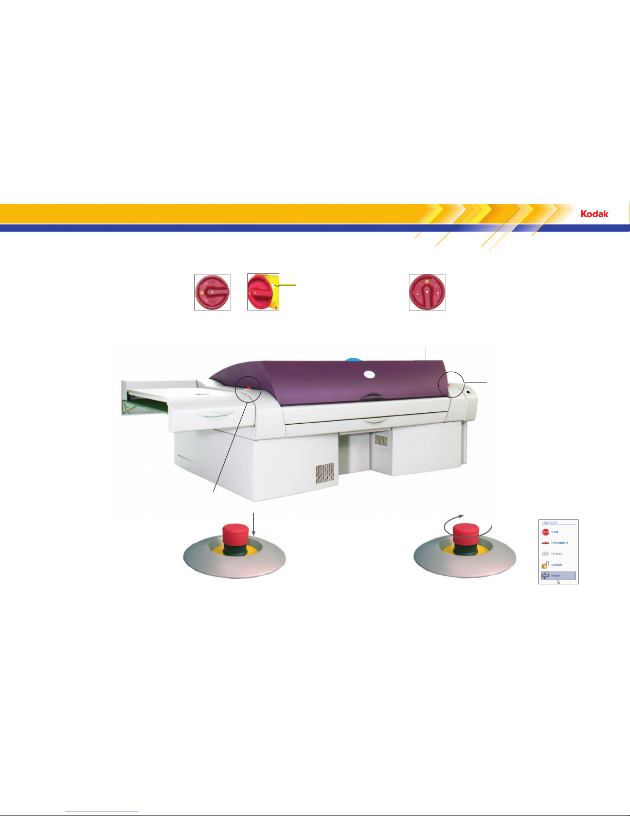
Emergency stop button
Emergency stop button
Power switch
Emergency stop locations
Emergency stop button
Press the emergency stop button to stop
mechanical movement and laser operation.
Activate an emergency stop device to stop mechanical movement and laser operation.
Power/emergency stop switch
The power switch disconnects power to the platesetter so
that you can safely perform maintenance procedures or
retrieve stuck media. When you are instructed to turn o
power to the platesetter, turn the switch counterclockwise to
the OFF position and secure it with a padlock.
To turn on the power,
turn the switch
clockwise to the ON
position.
Insert a padlock here.
OFF ON
The switch can be used as an emergency
stop mechanism when you cannot reach an
emergency stop button.
To reset the platesetter, turn the
emergency stop button clockwise until
it pops up and then select the Reset
operation in Print Console.
The emergency stop button stops laser operation
and mechanical movement, but the power remains
connected. If any internal or external emergency
stop button is pushed, you must reset the
platesetter before it can resume regular operations.
Page 4
3
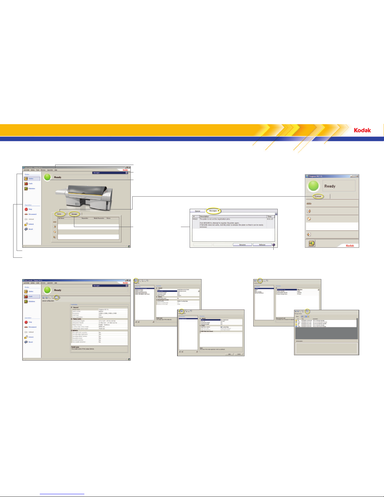
Using Print Console
Status mode—perform daily tasks
Tools mode—configure Print Console
Modes control what you see on-screen.
Operation buttons and menu items allow you to quickly perform everyday tasks. Only
buttons and menu items that are relevant to your platesetter appear on-screen.
For information about all screen elements, see the Print Console Help.
Important messages appear here.
The status light and text are visible from a distance.
Queue tab—displays the status
of plates as they move through
each stage in the platesetter
Messages tab—displays
error messages and tells how
to correct errors that have
suspended operations
Miniview mode—monitor plates
and workflow at the same time
Print Console Help
Device Configuration—view platesetter-specific information
Media Tool—define media sizes Preferences Tool—set preferences (for example, language)
Messages History—review recent messages
Registration Tool—define registration settings
Page 5
4
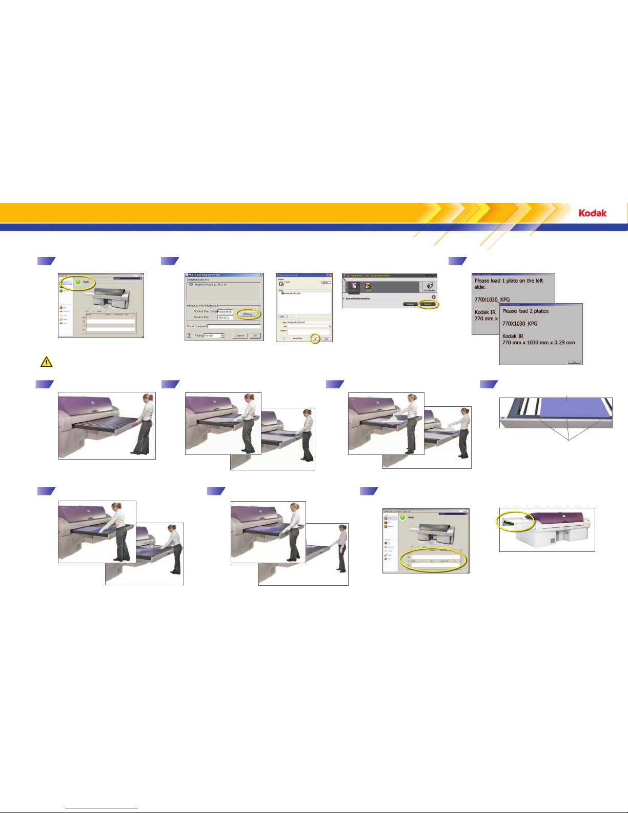
Double plates
Right side
Ensure that the platesetter has a
Ready status.
2 3
Ensure that the correct plate size is available
for loading.
Single plate
Double plates
4
Pull out the bypass load table.
5
Place the plate or plates on the load table.
6
Remove the slip sheet.
7
Align the plate or plates with the media
alignment labels.
Plate
Media alignment labels
8
Register the plate or plates. Position the
leading edge against the end stop.
9
Press a start button.
Double plates
Double plates
Single plate
Single plate
Left side
Loading and imaging a plate
Kodak Prinergy® Connect™ workflow
CAUTION: Wear protective gloves when handling plates to protect your hands from the sharp edges
and corners of the plates. Failure to wear protective gloves may result in minor or moderate injury.
In the workflow software, submit the file.
Kodak Brisque® workflow
Note: You must have a Prinergy Evo TIFF output
template and hot folder already set up.
Single plate
The exposed plate or plates exit the
platesetter through the bridge.
1
On the Print Console Queue tab, follow
the progress of the plate or plates
through the platesetter.
10
Kodak Prinergy Evo™ workflow
Accurate alignment ensures accurate
punching. Ensure that the plate is no farther
than 3 mm (0.12 in.) from the alignment
label.
Page 6

5
Operation
Turn on the platesetter
1
These operations are required for some of the
maintenance procedures below.
Turn o the platesetter
2
Reset the platesetter
3
Maintenance procedure Work to be done How often
Date work
completed
Exterior surfaces Clean
Weekly
Edge detection strip
1
4
Clean
Six months or
as needed
Plate roller
1
5
Clean
Rear fan filters
1
6
Replace
328-00036
Punch chip collection box
1, 3
Empty
Compressed air supply
(particulate filter only)1
8
Replace
328-00001
Power box intake air filter1
9
Replace
55-1292A
Heat exchanger intake air
filter
1, 2
10
Replace
55-1293A
As needed
Debris removal filter1
Replace
MDRC: 252-11119A
UDRC: 57-8792D
As needed
1
This procedure is included in this visual reference guide.
2
This procedure applies only to models with the heat exchanger option.
3
This procedure applies only to models with the punch option.
For more information, see the Print Console User Guide.
Operator maintenance schedule
4
5
1
2
7
8
10
9
3
6
7
11
11
Page 7

6
Turn o the compressed air.
0 psi
Replacing the air supply particulate filter
1
3 4
Unscrew the bowl. Pull the tab down and turn
the bowl 45° to the left.
6
Clean the inside of the bowl with
warm water and mild soap.
7
Replace the O-ring, if necessary.
8
Reattach the bowl. Push the bowl up
and turn it to the right until it clicks.
9
Turn on the compressed air.
100–125 psi
5
Install the new filter.
Particulate filter
Bowl
Tab
CAUTION: To prevent possible serious injury
from flying parts or loud noise caused by
the release of high-pressure air during filter
replacement, confirm that the compressed air
supply is turned o before installing the new
air supply particulate filter.
Particulate filter
Open the rear hood:
a
In Print Console, unlock
the panels.
b
Turn the handle counterclockwise and lift the hood.
2
Use a slotted screwdriver
to loosen the two screws
that secure the rear panel
to the platesetter.
Close the rear panel, tighten the
screws, and close the rear hood.
10
In Print Console, lock the panels.
11
Page 8

7
Cleaning inside the platesetter
Cleaning the edge detection strip
Rotate the drum to expose the edge detection strip.
Dampen a cloth with water, and slide
it along the edge detection strip.
3 4
Cleaning the plate roller
Locate the blue plate roller.
Dampen a lint-free cloth with water,
and slide the cloth over the plate roller.
3
4
Edge detection strips
Note: Do not clean the plate roller with
detergent or alcohol.
5
Close the rear hood:
a
In Print Console, lock the panels.
b
Pull down the rear hood.
1
Ensure that the platesetter
is in an idle state.
2
Open the rear hood:
a
In Print Console, unlock the panels.
b
Turn the handle counterclockwise and lift the hood.
The interior of the platesetter is
exposed for cleaning.
5
Close the rear hood:
a
In Print Console, lock the panels.
b
Pull down the rear hood.
Page 9

8
Replacing the power box intake air filter
Replacing the heat exchanger intake air filter
1
Power box filter panel
Open the power box filter panel:
2
Remove the panel.
3
Remove the old intake air filter
from the panel.
4
Install the new intake air filter.
a
Loosen the thumb screws.
b
Close the power box filter panel:
a
Replace the panel.
b
Tighten the thumb screws.
Debris removal panel
1
Open the debris removal panel:
a
Pull the debris removal panel
toward you.
b
Lift and remove the panel.
2
Remove the old intake air filter.
3
Install the new intake air filter.
Power box intake air filter
Heat exchanger intake air filter
4
Close the debris removal panel:
a
Replace the debris removal
panel.
b
Push the panel back into
place.
Page 10

9
Replacing the rear fan filters
1
Open the hood:
a
In Print Console, unlock the panels.
b
Push the black button and lift the rear hood.
5
4
2
Rear fan filter
3
Remove the old rear fan filters and insert new
filters.
Use the air flow arrow as a guideline for correct
installation. The arrow should point toward the
fan so that the side with the wire mesh faces the
interior of the platesetter.
The Magnus VLF platesetter has two fans at the rear of the platesetter. Replace the filters for these fans every six months.
Use a slotted screwdriver
to loosen the two screws
that secure the rear panel
to the platesetter.
Close the rear panel, tighten the
screws, and close the rear hood.
In Print Console, lock the panels.
Page 11

10
Raising the punch assembly
1
Open the rear hood:
a
In Print Console, unlock the panels.
b
Push the black button and lift the rear hood.
Punch assembly
2
Standing in front of the punch assembly, pull
it toward you.
3
Remove the lifting handle from its storage location.
Lifting handle
4
Push in the blue lock-out knob.
Blue lock-out knob
Crankshaft
5
Attach the lifting handle to the crankshaft
and slowly turn the lifting handle clockwise.
Lift the punch assembly until it reaches your desired
level or is in the fully up position.
The blue light turns on when the
punch table starts to lift.
The punch assembly in the fully up
position.
You may need to raise the punch assembly to perform a recovery procedure. Raising the punch
assembly provides access to the unload table, the load table, and the top of the drum.
Page 12

11
Lowering the punch assembly from the raised position
1
Attach the lifting handle to the crankshaft and slowly turn the lifting handle counterclockwise.
Continue lowering the punch assembly until the blue light turns o.
2
Return the lifting handle to its storage location.
Lifting handle
3
Push the punch assembly forward until you
hear a click. You will feel some resistance.
5
In Print Console, lock the panels.
4
Close the rear hood.
Note: If you do not push the punch
assembly fully forward, you will not be
able to close the rear hood.
Emptying the punch chip collection box
1
Pull out the chip collection box.
2
Empty the chip collection box.
3
Reinsert the chip collection box.
The blue light turns o when
the punch assembly is in its
original position.
Page 13

12
Replacing the debris removal filter
3
4
1
1110
9876
5
12
Shut down the
platesetter by turning
the power switch to
the OFF position.
Pull the debris panel toward
you. The panel unlatches.
Lift the panel up and away
from the platesetter and put
it in an out-of-the-way place.
Vacuum any dust
deposits from around
the tube in the center of
the inner lid. Ensure that
no debris falls into the
filter compartment.
Release the canister lid on the debris
removel unit by pulling the pins on
either side.
Slide the debris removal unit out of
the platesetter and remove the old
filter by grasping the handle and
pulling up.
Place the used filter in
a bag for disposal. A
bag is provided with the
replacement filter.
Remove the filter spacer
from the bottom of the filter
compartment and put it aside.
Reinstall the filter spacer in the
bottom of the filter compartment.
Wipe the inside of the inner lid, the
deck, and the interior surfaces of
the filter compartment with a clean
rag dampened with water and mild
detergent. Remove all residue by wiping
thoroughly with a clean, damp rag.
15
14
13
WARNING: Do not let water or other liquids run freely into the
platesetter. This can result in serious injury from electrical shock as
well as damage to your platesetter.
Press down on the cannister lid
until you hear a click.
Lower the new filter into the filter
compartment with the gasket
facing up. Ensure that the filter is
fully seated on the spacer.
Slide the debris removal
unit back into the
platesetter.
Align the locating holes
on the bottom of the
panel with the locating
pins on the platesetter.
Push the upper corners of
the panel until you hear
both latches click.
On the Print Console Messages tab,
follow the instructions for clearing the
message.
Wash your hands.
Print Console indicates when the debris removal filter is full and needs to be replaced. When the full filter message appears, you will not be able to continue imaging until the filter is replaced.
Click Eject to eject any plates that are
in the platesetter.
2
Clean the debris removal compartment:
b
a
Reinstall the filter:
b
a
Gasket
Filter spacer
Filter
Replace the panel:
a
b
Lower the bottom of the
panel onto the pins.
Always have a spare filter on hand.
Page 14

13
Removing a plate flyo
CAUTION: Wear protective
gloves when handling
plates to protect your
hands from the sharp edges
and corners of the plates.
Failure to wear protective
gloves may result in minor
or moderate injury.
8
Reposition the trailing-edge clamps:
a
b
Using the clamp removal tool, lift the trailingedge clamps and reposition them. Twist and
pull to remove the clamp removal tool.
Align the trailing-edge clamps so
that their edges press against the
parking pins.
Parking pins
Edge of trailing-edge clamp
9
Replace the rear panel and close
the rear hood.
10
In Print Console, lock the panels.
11
In Print Console, click Media
Removed.
3
Pull the cooling fans away
from the drum.
Cooling fans
4
Rotate the drum to expose the
trailing-edge clamps.
5
Using the clamp removal tool, slide the
trailing-edge clamps o the plate.
6
Fold over the corners of
the plate.
7
Press the leading-edge clamps
to free the plate.
The clamp
removal tool
is stored in
the rear of the
platesetter.
An error message about the
flyo appears.
1
Open the hood:
a
In Print Console, unlock the
panels.
b
Push the black button and lift the rear hood.
2
Use a slotted screwdriver
to loosen the two screws
that secure the rear panel
to the platesetter.
Page 15

14
Plate registration
Punch table
Correct
Plate positioned on the punch table
using Kodak registration. (An X
represents the platesetter registration
pins, and the square shapes represent
the punch registration pins.)
The image is correctly aligned (parallel)
with the punched holes or bend.
The image and punched holes are
aligned without side shift.
Plate
Kodak side registration point
Incorrect
Plate positioned on the punch table
using non-Kodak registration. (An X
represents the platesetter registration
pins, and the square shapes represent
the punch registration pins.)
The image is incorrectly aligned (rotated)
with the punched holes or bend.
Platesetter registration point
The image and punched holes are not
aligned and are shifted sideways.
Non-Kodak side registration point
Registration method
Use the Print Console Registration tool
to create, modify, and delete sets of
registration parameters (registrations).
Registrations ensure that plates imaged
on your platesetter are configured to
match the registration requirements of
the press as closely as possible.
Use the parameters in the Image
category to specify which registration
method to use. The registration
methods that are available for selection
depend on the options that are enabled
on your platesetter.
For more information, see the Print
Console Help.
Side Edge registration method
Third registration point
(fixed)
Registration edge on the
platesetter drum
Registration edge on
the press cylinder
Registration edge on the platesetter drum
Registration edge on the press cylinder
Third registration point
(fixed)
Leading Edge registration method
Leading Edge (third point configurable) registration method
Third registration point—configure
Distance to third point.
Registration edge on the platesetter drum
Registration edge on the press cylinder
Third registration point—
configure (a) Spacing
between points and Center
the points. If Center the
points is No, configure (b)
Distance to first point.
Registration edge on
the platesetter drum
Registration edge on
the press cylinder
Configurable Side Edge registration method
Page 16

Eastman Kodak Company
343 State Street
Rochester, NY 14650 U.S.A.
© Kodak, 2010. All rights reserved.
TM: Kodak
To learn more about solutions from Kodak, visit
graphics.kodak.com
Subject to technical change without notice.
 Loading...