

Kodak DryView 8300, Kodak DryView 8610, Kodak DryView 8600 Service Bulletins

Kodak DryView
8300/8600/8610 LASER IMAGING SYSTEMS
Service Bulletins

SERVICE BULLETIN
Health Imaging Products
Eastman Kodak Company, Health Imaging, Rochester, NY 14650
SERVICE BULLETIN NO. 884 June 2004
Kodak DryView 8300 LASER IMAGER
Service Codes: 1425, 1426, 1427
New Solution for EC 27 or EC 28
Caused by FILM Stalling in the PROCESSOR
Purpose
The purpose of this Service Bulletin is to communicate that the cause of, and solution for, FILM
stalling in the PROCESSOR has been determined.
Description
The main cause of FILM stalling in the PROCESSOR is the inability of the RUBBER IDLER
ROLLER at the entrance to the PROCESSOR to turn freely as FILM enters the PROCESSOR. This
condition causes the FILM to slip and after some time, the software times out and displays EC 27 or
EC 28.
Note: EC 28 is usually caused by FILM slipping at the entrance to the PROCESSOR. However, the
EC is displayed when the FILM does not exit in the time expected by the software. This is
because if the FILM gets a slow start into the PROCESSOR, the FILM may eventually pass
through the PROCESSOR, but the FILM still does not exit in the time expected by the
software.
Solution
If an IMAGER experiences repetitive EC 27 or EC 28 errors, replace the gray plastic BUSHINGS
that hold the RUBBER IDLER ROLLER in place with a pair of METAL BALL BEARING
BUSHINGS (7E9722). Replace the gray plastic BUSHINGS only at the PROCESSOR entrance.
©Eastman Kodak Company, 2004 Eastman Kodak Company Restricted Pub No. 7F6652

Service Information
Gary Ketch, Service Engineer-Oakdale
For more information please contact:
Eastman Kodak Company
Health Imaging
1 Imation Way
Discovery Building 3B-62
Oakdale, MN 55128-3414, USA
1-800-328-2910
Kodak and DryView are trademarks of Eastman Kodak Company.
Printed in the USA. Pub No. 7F6652
©Eastman Kodak Company, 2004
Rochester, NY 14650
HEALTH IMAGING

SERVICE BULLETIN
Health Imaging Products
Eastman Kodak Company, Health Imaging, Rochester, NY 14650
SERVICE BULLETIN NO. 860 APRIL 2004
Kodak DryView 8300 LASER IMAGER
Service Codes: 1425, 1426, 1427
ProComm Plus COMMUNICATIONS PROGRAM To Be Used When Uploading System
Software
Purpose
The purpose of this Service Bulletin is to communicate that the Hyperterminal
COMMUNICATIONS PROGRAM does not function adequately when used with the newest models
of LAPTOP COMPUTERS.
Description
The inefficiency of the Hyperterminal COMMUNICATIONS PROGRAM, when used with the new
higher-speed LAPTOP COMPUTERS, can cause it to take up to four hours to upload new system
software into the Kodak DryView 8300 LASER IMAGER. The Pro Comm Plus
COMMUNICATIONS PROGRAM is a more sophisticated program that will allow software
uploads to take no longer than 10-12 minutes. In addition, the ProComm Plus
COMMUNICATIONS PROGRAM will provide an estimate of the total time required for a software
upload as well as a progress gauge.
Procedure
The next time you install a software upgrade in a Kodak DryView 8300 LASER IMAGER, follow
the procedure in paragraph 2-9-2 in the SERVICE MANUAL for the Kodak DryView 8300
LASER IMAGER.
Eastman Kodak Company, 2004 Eastman Kodak Company Restricted Pub No. 7F6199

Gary Ketch, Service Engineer-Oakdale
For more information please contact:
Eastman Kodak Company
Health Imaging
1 Imation Way
Discovery Building 3B-62
Oakdale, MN 55128-3414, USA
1-800-328-2910
Kodak and DryView are trademarks of Eastman Kodak Company.
Printed in the USA. Pub No. 7F6199
©Eastman Kodak Company, 2004
Rochester, NY 14650
HEALTH IMAGING
SERVICE BULLETIN
Health Imaging Products
Eastman Kodak Company, Health Imaging, Rochester, NY 14650
SERVICE BULLETIN NO. 26 NOVEMBER 2003
1425, 1426, 1427 Kodak DryView 8300 LASER IMAGER
Procedure to Reduce Film Errors (EC33)
Purpose
The purpose of this Service Bulletin is to communicate that there is a relatively easy way to reduce
the number of film-feed retries and failures that result in EC 33. On your next service call, examine
the Error Log, which can be accessed from the Test Menu (911). If there are EC 33s listed in the log,
perform the procedure below.
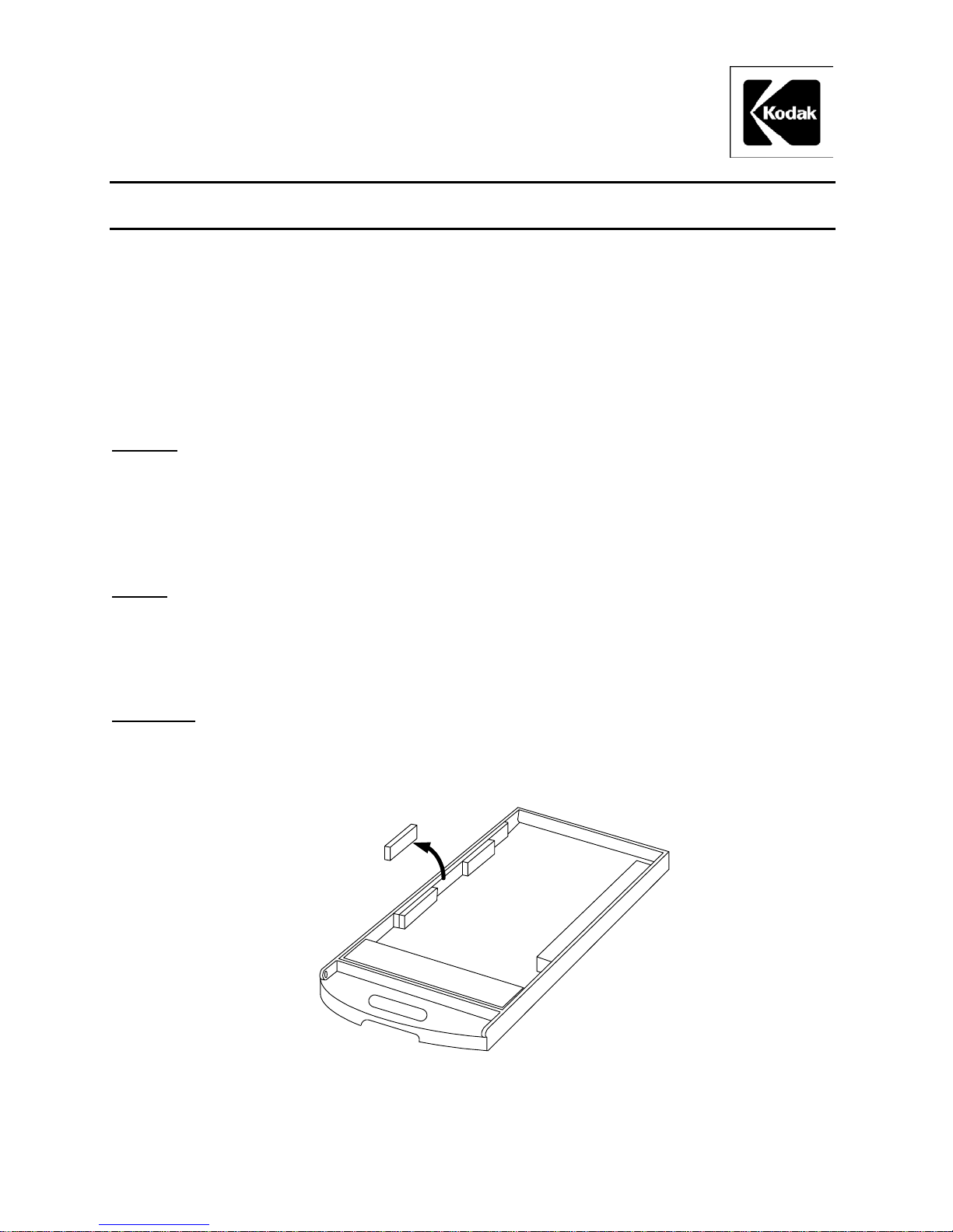
Details
Excessive pressure applied to the film by the registration foam, on the left side of the FILM TRAY,
can cause film-feed retries and failures. The easiest way to reduce this pressure is to remove the
middle third of the six-inch foam that holds the film in place.
Procedure
With a ruler and a sharp knife, measure, cut and remove the middle two inches of the registration
foam as shown in the illustration. Be sure to remove only the middle two inches of foam. Clear the
FILM TRAY of all foam debris resulting from the cuts.
Removing Middle Two-Inch Section of Registration Foam
Eastman Kodak Company, 2003 Pub No. 7F3182

Gary J. Ketch, Service Engineer-Oakdale
For more information please contact:
Eastman Kodak Company
Health Imaging
1 Imation Way
Discovery Building 3B-62
Oakdale, MN 55128-3414, USA
1-800-328-2910
Kodak and DryView are trademarks.
Printed in the USA. Pub No. 7F3182
©Eastman Kodak Company, 2003
Rochester, NY 14650
HEALTH IMAGING

SERVICE BULLETIN
Health Imaging Products
Eastman Kodak Company, Health Imaging, Rochester, NY 14650
SERVICE BULLETIN NO. 25 November 2002
1425, 1426 and 1427 Kodak DryView 8300 LASER IMAGER
GAS SHOCK ABSORBER May Allow TOP COVER to Close
Purpose
The purpose of this service bulletin is to communicate that if the GAS SHOCK ABSORBER becomes weak,
it may allow the TOP COVER to close even if the operator does not want it to close.
Procedure
On the next service call and then during each PM call thereafter, check the operation of the GAS SHOCK
ABSORBER (SP78-8100-0495-8) that is used to keep the TOP COVER open. If it fails to securely hold the
TOP COVER in its full open position, replace it.
ãEastman Kodak Company, 2002 Pub No. 8E7557

Gary Ketch, Service Engineer-Oakdale
For more information please contact:
Eastman Kodak Company
Health Imaging
1 Imation Way
Discovery Building 3B-62
Oakdale, MN 55128-3414, USA
1-800-328-2910
Kodak and DryView are trademarks.
Printed in the USA. Pub No. 8E7557
©Eastman Kodak Company, 2002
Rochester, NY 14650
HEALTH IMAGING

SERVICE BULLETIN
Health Imaging Products
Eastman Kodak Company, Health Imaging, Rochester, NY 14650
SERVICE BULLETIN NO. 24 October 2002
1425, 1426 and 1427 Kodak DryView 8300 LASER IMAGER
Scratch Reduction Tool Available
Purpose
The purpose of this service bulletin is to provide information about a new tool that can be used to reduce
repetitive scratching caused by particles or nicks on the FILM GUIDE SCOOP.
Procedure
To assist in the removal of repetitive scratches caused by particles or nicks on the lower FILM GUIDE
SCOOP order the CROCUS CLOTH KIT 8E2083.
The CROCUS CLOTH is inserted manually onto the SCOOP, in the same manner as a piece of film would
travel on the scoop. It is then rubbed against the entire length of the SCOOP so that it reaches the top edge,
near the CAPSTAN ROLLER.
Once the polishing process is complete, clean the SCOOP thoroughly with an alcohol wipe such as a
TX-1065 to remove any particles that were dislodged by the CROCUS CLOTH.
ãEastman Kodak Company, 2002 Pub No. 8E6997

Gary Ketch, Service Engineer-Oakdale
For more information please contact:
Eastman Kodak Company
Health Imaging
1 Imation Way
Discovery Building 3B-62
Oakdale, MN 55128-3414, USA
1-800-328-2910
Kodak and DryView are trademarks.
Printed in the USA. Pub No. 8E6997
©Eastman Kodak Company
Rochester, NY 14650
HEALTH IMAGING

SERVICE BULLETIN
Health Imaging Products
Eastman Kodak Company, Health Imaging, Rochester, NY 14650
SERVICE BULLETIN NO. 23 AUGUST 2002
1425, 1426 and 1427 Kodak DryView 8300 LASER IMAGER
Instructions for Grounding the PROCESSOR ASSEMBLY to Eliminate EC88s
Purpose
The purpose of this service bulletin is to provide instructions for grounding the PROCESSOR ASSEMBLY
using the PROCESSOR GROUNDING HARDWARE KIT, 8E2003.
Procedure
1. Remove the SPRING CLIPS from the FRAME and CLAMSHELL of the PROCESSOR
ASSEMBLY (see Fig. 1).
2. Attach one end of the WIRE (supplied in the KIT) to the STRIPPER ASSEMBLY using the right
mounting SCREW of the STRIPPER ASSEMBLY (see Fig. 2).
3. Attach one end of 1 small STRAP (supplied in the KIT) along with the loose end of the WIRE
referred to in Step 2, to the FRAME where the CLIP was removed in Step 1 (see Fig. 2).
4. Remove the SCREW holding the ROLLER ASSEMBLY MOUNTING ROD, and using the supplied
SPACER and SCREW, attach the loose end of the small STRAP to the ROLLER ASSEMBLY
MOUNTING ROD (see Fig. 2).
5. Repeat Steps 3 and 4 to attach the remaining small STRAP to either side of the CLAMSHELL
portion of the PROCESSOR ASSEMBLY.
ãEastman Kodak Company, 2002 Pub No. 8E6688
Figure 1
1. Remove
2. Connect WIRE to
STRIPPER ASSEMBLY
Figure 2
Page 2 Pub No. 8E6688
4. Add STRAP, SPACER and
SCREW to ROLLER
ASSEMBLY
3. Connect WIRE to one
end of STRAP

Gary Ketch, Service Engineer-Oakdale
For more information please contact:
Eastman Kodak Company
Health Imaging
1 Imation Way
Discovery Building 3B-62
Oakdale, MN 55128-3414, USA
1-800-328-2910
Pub No. 8E6688 Page 3

SERVICE BULLETIN
Health Imaging Products
Eastman Kodak Company, Health Imaging, Rochester, NY 14650
SERVICE BULLETIN NO. 22 AUGUST 2002
1425, 1426 and 1427 Kodak DryView 8300 LASER IMAGER
Clicking Sound Coming From Left Side of IMAGER
Purpose
The purpose of this service bulletin is to communicate what causes, and how to correct the intermittent
clicking sound that may be heard in the left side of the IMAGER.
Cause
The BEARINGS inside the COMPOUND PULLEY are loose causing them to move in and out. The
BEARING ASSEMBLIES are supposed to be glued into the COMPOUND PULLEY so that they can’t be
removed.
Solution
Replace the COMPOUND PULLEY 78-8100-0410-7. Before installing it into the IMAGER, be sure that
both BEARINGS are firmly in place within the COMPOUND PULLEY.
ãEastman Kodak Company, 2002 Pub No. 8E6674

Gary Ketch, Service Engineer-Oakdale
For more information please contact:
Eastman Kodak Company
Health Imaging
1 Imation Way
Discovery Building 3B-61
Oakdale, MN 55128-3414, USA
1-800-328-2910
Kodak and DryView are trademarks.
Printed in the USA. Pub No. 8E6674
©Eastman Kodak Company, 2002
Rochester, NY 14650
HEALTH IMAGING

Health Imaging
Technical Bulletin 8300
5-9/00 Clicking Sound from Left Side of Imager
Problem:
Intermittent clicking sound from the left side of the imager.
Cause:
The Compound Pulley (78-8100-0410-7), which transfers power from the main drive belt to the Separator
Assembly, is made up of a black plastic pulley housing and two bearings. If one of the bearings starts to
deteriorate, it will cause the pulley to emit an intermittent clicking sound.
Solution:
Replace the bad bearing. The bearings are the same Common Bearing (78-8113-2008-0) used throughout
the imager, and can be replaced individually. If the Pulley Mounting Shaft (78-8100-0614-4) has been
damaged by the bearing, it also can be easily replaced.
6-9/00 Thumping Sound from Left Side of Imager
Problem:
Occasional thumping sound from the left side of the imager.
Cause:
The main drive belt, which connects the main stepper motor to the Separator Assembly and the Processor
Assembly, can skip a tooth from time to time, causing the thumping sound. This skipping of teeth, which
can be caused by a loose belt, results in belt wear. The belt wear is evidenced by a buildup of black
“powder” (belt particles) on the left side frame and base plate. If the problem condition has existed for a
long time, the black powder can build up on the teeth of the Compound (two part) Pulley. This buildup on
the pulley can cause the belt to continue to skip, even after its tension has been adjusted.
Solution:
Tighten the tension of the main drive belt, as necessary, by adjusting the eccentric. Check for powder
buildup on the Compound Pulley, and clean the pulley, as necessary. (The Compound Pulley is black, so
the powder buildup is not easy to see.)
Eastman Kodak Company
Health Imaging Products
1 Imation Way
Oakdale, MN 55128
http://www.kodak.com
Printed in the U.S.A.
© Kodak 2000 Sept.

7-9/00 Thin Horizontal Line Across Width of Film
Problem:
A horizontal line appears across the film, about 5-1/2 inches from the top. It may look like image data is
missing in one or two scan lines. The line, which may be intermittent, occurs across the entire width of the
film, traversing both the image and the borders.
Cause:
The operator may have removed a jam and attempted to snap the upper film guide back into place, but only
one side got latched. The line is caused by the film hesitating while it is being imaged, as it enters the
processor assembly.
Solution:
As a phone fix, ask the operator to reseat the upper film guide and ensure that it is snapped into place on
both sides.
2

Model 8300 Technical Bulletins
7-2/98
ATL HDI DICOM Print Setup
Currently the HDI 3000 and 5000 have DICOM print available, but the HDI 1000 does not. Use the
following procedures to change the DICOM print parameters on the HDI 3000 and 5000.
All options are selected by moving the cursor with the trackball to the appropriate menu item and
pressing the Select key.
Network Printer Configuration Parameters
1. Press the Setups key to access the Setups Options directory.
2. Select Access Link Directory.
3. Select Configuration Files.
4. Select Edit.
5. Select Host Table.
6. Scroll to and select Image Parameters.

Model 8300 Technical Bulletins
Use the keyboard to insert the 8300 network printer configuration parameters as follows:
Alias IP Address Port Number Model ID AE Title
3M8300_254 Determined by System
Administrator
104 3m_8300_Printer_v1 3M_8300
7. Close the menu
Device File Table
The 8300 device file is not in the system software because the memory overflow problem had not
been resolved when the DICOM print software for the HDI 3000 was released. ATL plans an 8300
disk that will be used to install the table on the HDI 3000 and 5000. The table can also be installed
manually.
1. Press the Setups key to access the Setups Options directory.
2. Select Access Link Directory.
3. Select Configuration Files.
4. Select Edit.
5. Select Devices.

Model 8300 Technical Bulletins
6. Move the cursor to the appropriate file name (such as 3M–8300.V1) and press the Select key to
display it in the selection window.
7. Move the cursor to OK to display the device file.
8. Scroll and edit the device file. For the 8300, the $STAN_SUPPORT and
$STAN_IMAGE_PRINTER sections of the device file should be as follows:

Model 8300 Technical Bulletins
$STAN_SUPPORT $STAN_IMAGE_PRINTER
Version
Dicom 30
Def_Printer Class Grey
Verify Yes Def_Film Size 8INX10IN
US_Store No Def_Film Medium BLUE _FILM
USMF_Store No Def_Film Destination PROCESSOR
Pat_Root_Find
No
No Def_Display Format STANDARD \2,3
Pat_Root_Move No Def_Orientation PORTRAIT
Grey_Print Yes Def_Config Info LUT=0,8
Color_Print No Max_Copies 10
Max_Density_Avail-
able
300
Min_Density_Available 0
Def_Max Density 270
Def_Min Density 0
Def_Border Density 300
Def_Empty Density 300
9. Close the menu

Model 8300 Technical Bulletins
Operator accessible printer parameters
The clinical operators of the HDI 3000 will not access the above tables. They can select format,
orientation, maximum and minimum density, and number of copies within the operator’s B&W printer
menu. The HDI 3000 will be installed with the LUT set for the customer by ATL marketing personnel,
not to be changed unless the customer wants a different look for the films.

TM
DryView Laser
Imager
Model 8300
Technical Bulletin 12/28/98
2512/98 Cart Commercially Available
Rubbermaid makes a flat shelf cart that can support up to 200 lbs. and is big enough for the 8300.
The model number is 4505 and costs approximately $120. Thanks to John Bennie for supplying
this tip.
2612/98 Remote Acquire Unit Available From SPC
Some ultrasound customers want the 8300 to be able to acquire images by pressing the Print or
Expose keys on their ultrasound consoles instead of using the 8300's remote keypad. There is now
an interface device available that connects between the 8300, its remote keypad and the ultrasound
unit which will trigger the 8300 to acquire when the signal is received from the ultrasound. The kit
(interface box and cable) is available through sales with part number 78811427976 and has a list
price of $195.
Imation Enterprises Corp.
1 Imation Place
Oakdale, MN 551283414
888 466 3456 phone
888 704 7100 fax
http://www.imation.com
Printed in the U.S.A.
Imation 1998 December

DryView Laser Imager
Model 8300
Technical Bulletin 07/30/99
3-6/99 Film Count (Exposures) Meter Reading
There are two quick ways to check the film count on the 8300. First, press either Setup button,
followed by 999 and Enter. Then arrow down to item 10. Exposures. The film count labelled
Exposures will be displayed. Press Exit to return the 8300 to the Ready condition. A second and
quicker way is to press Test, followed by 911 and Enter. The first menu item displayed is 1. Examine
System Error Log. Press Enter and the first log entry will display the film count labelled as
Exposures. Press Exit twice to return the 8300 to the Ready condition.
Kodak Health Imaging
1 Imation Place
Discovery 4B-74
Oakdale, MN 55125
Tel. (651) 704-4000
http://www.kodak.com
Printed in the U.S.A.
Kodak 1999 July

Health Imaging
Technical Bulletin 8300
8-11/00 POEIB No longer Available
The POEIB was originally design ed as an inte rface t o allow the DryView 8300 to be connected to a nd print
from an 8800. There is a highly intermittent software bug in the 8800 that causes the system to hang up.
Because of the age of this equipment, and because the PACS Link 9410 Acquisition System is a viable
substitute, the POEIB is no longer available f or sale, and no new insta llations of this equipment are to be
made.
Eastman Kodak Company
Health Imaging Products
1 Imation Way
Oakdale, MN 55128
http://www.kodak.com
Printed in the U.S.A.
© Kodak 2000 Dec.

Blank Page
2

Health Imaging
Technical Bulletin DryView 8300
9-01/01 DryView Film Numbering Code Change
There will be a slight change in what the Lumonics system will print on the edge of all sheets of DryView
film. The letter that designates whether the product is DVB, DVC, or DVM has been eliminated. Following
is an example of what used to be printed on the film:
KODAK DRYVIEW M EXP 03/01 D2231-01-B 03 2945
Where: KODAK = Company name
DRYVIEW = Product
M = Subproduct: either M (Mammo), B (Blue), or C (Clear)
EXP 03/01 = Expiration date
D = Plant code for White City
2231 = Lot number
-01 = Jumbo number
-B = Band within jumbo
03 = Sheeter number
2945 = Sheet number within band
This is how the new printing will look:
KODAK DRYVIEW EXP 03/01 D2231-01-B 03 2945
Note that all items are the same as in the earlier format except the letter designation between DRYVIEW
and the expiration date has been eliminated.
Eastman Kodak Company
Health Imaging Products
1 Imation Way
Oakdale, MN 55128
http://www.kodak.com
Printed in the U.S.A.
© Kodak 2001 Jan.

Health Imaging
Technical Bulletin DryView 8300
10-02/01 EC27 - Film Stopping in Processor
Problem
Film takes too long to pass through the processor, and the software times out, producing an Error Code 27.
Cause
Film did not get a positive start into the processor. There are several possible causes of this:
1. Bowed entrance guides caused by over-tightening of the mounting hardware during production. The
bow produces a high resistance in the film path. (See solution 1 below.)
2. Metal entrance roller is slipping on its shaft. (See Solution 2 below.)
3. Rubber entrance pinch roller has become glazed or hardened and is no longer grabbing the leading
edge of the film.
Solution
1. Remove the processor assembly and loosen the screws and/or nuts that secure the entrance guides
(located on the under side). Confirm that the guides are no longer bowed. Then tighten the hardware
only enough to keep the guides from moving.
2. Remove the metal entrance roller and confirm that the drive side shaft is securely attached to the roller.
If it is not, remove the shaft, put a small drop of epoxy in the roller and slowly press the shaft back into
the roller. If you are unsuccessful in securing the shaft, replace the roller (78-8100-0293-7).
3. Clean the rubber roller with alcohol. If the surface does not appear to be soft and supple after cleaning,
replace the roller (78-8113-2104-7).
Eastman Kodak Company
Health Imaging Products
1 Imation Way
Oakdale, MN 55128
http://www.kodak.com
Printed in the U.S.A.
© Kodak 2001 Feb.

This page is intentionally left blank.
2
 Loading...