

Page 1

Publication No. SM5766-1
23JUL01
Supersedes SM5766 -1
13MAY97
SERVICE MANUAL
for the
Kodak Ektalite 500 PROJECTOR
PROJECTORS
Service Code: 5766
A091_4000BA
Page 2

WIRE ASSEMBLIES. . . . . . . . . . . . . . . . . . . . . . . . . . . . . . . . . . . . . . . . . . . . . 5
Removal for the LOWER HOUSING . . . . . . . . . . . . . . . . . . . . . . . . . . . . . . . 6
Installation for the LOWER HOUSING . . . . . . . . . . . . . . . . . . . . . . . . . . . . . 6
Removal for the FAN SHAFT ASSEMBLY . . . . . . . . . . . . . . . . . . . . . . . . . . 7
Installation for the FAN SHAFT ASSEMBLY . . . . . . . . . . . . . . . . . . . . . . . . 10
Removal for the MOTOR . . . . . . . . . . . . . . . . . . . . . . . . . . . . . . . . . . . . . . . . 11
Installation for the MOTOR . . . . . . . . . . . . . . . . . . . . . . . . . . . . . . . . . . . . . . 13
Removal for the WORM PULLEY and MECHANISM BELT . . . . . . . . . . . . . 13
Installation for the WORM PULLEY and MECHANISM BELT . . . . . . . . . . . 14
Removal for the THERMAL FUSE ASSEMBLY . . . . . . . . . . . . . . . . . . . . . . 15
Installation for the THERMAL FUSE ASSEMBLY . . . . . . . . . . . . . . . . . . . . 16
Removal for the LAMP MODULE RECEPTACLE. . . . . . . . . . . . . . . . . . . . . 17
Installation for the LAMP MODULE RECEPTACLE . . . . . . . . . . . . . . . . . . . 18
Removal for the CYCLE SOLENOID ASSEMBLY . . . . . . . . . . . . . . . . . . . . 19
Installation for the CYCLE SOLENOID ASSEMBLY . . . . . . . . . . . . . . . . . . 20
Removal for the MECHANISM ASSEMBLY . . . . . . . . . . . . . . . . . . . . . . . . . 21
Installation for the MECHANISM ASSEMBLY . . . . . . . . . . . . . . . . . . . . . . . 22
Removal for the AUTO-FOCUS BRACKET ASSEMBLY - 1500 and
2000 PROJECTORS Only. . . . . . . . . . . . . . . . . . . . . . . . . . . . . . . . . . . . . . 23
Installation for the AUTO-FOCUS BRACKET ASSEMBLY - 1500 and
2000 PROJECTORS Only. . . . . . . . . . . . . . . . . . . . . . . . . . . . . . . . . . . . . . 24
Removal for the CAM STACK ASSEMBLY and CYCLE LEVER ASSEMBLY 24
Installation for the CAM STACK ASSEMBLY and
CYCLE LEVER ASSEMBLY . . . . . . . . . . . . . . . . . . . . . . . . . . . . . . . . . . . . 29
Removal for the Style 2 LAMP SOCKET TERMINAL ASSEMBLY . . . . . . . 30
Page 3

Installation for the LAMP SOCKET TERMINAL ASSEMBLY . . . . . . . . . . . 31
Removal for the LENS MOUNT ASSE MBLY - 1500 and
2000 PROJECTORS Only. . . . . . . . . . . . . . . . . . . . . . . . . . . . . . . . . . . . . . 32
Installation for the LENS M OUNT ASSEMBLY - 1500 and
2000 PROJECTORS Only. . . . . . . . . . . . . . . . . . . . . . . . . . . . . . . . . . . . . . 33
Removal for the LENS MOUNT ASSE MBLY - 500 and
1000 PROJECTORS Only. . . . . . . . . . . . . . . . . . . . . . . . . . . . . . . . . . . . . . 33
Installation for the LENS M OUNT ASSEMBLY - 500 and
1000 PROJECTORS Only. . . . . . . . . . . . . . . . . . . . . . . . . . . . . . . . . . . . . . 34
Removal for the AUTO-FOCUS SWITCH ASSEMBLY -
Models 1500 and 2000 PRO JECTORS Only . . . . . . . . . . . . . . . . . . . . . . . 34
Installation for the AUTO-FOCUS SWITCH ASSEMBLY -
Models 500 and 2000 PROJECTORS Only. . . . . . . . . . . . . . . . . . . . . . . . 35
Removal for the FOCUS SHAFT ASSEMBLY -
1500 and 2000 PROJ ECTORS Only . . . . . . . . . . . . . . . . . . . . . . . . . . . . . 36
Installation for the FOCUS SHAFT ASSEMBLY - 1500 and
2000 PROJECTORS Only. . . . . . . . . . . . . . . . . . . . . . . . . . . . . . . . . . . . . . 38
Removal for the FOCUS SHAFT ASSEMBLY - 500 and
1000 PROJECTORS Only. . . . . . . . . . . . . . . . . . . . . . . . . . . . . . . . . . . . . . 38
Installation for the FOCUS SHAFT ASSEMBLY - 500 and
1000 PROJECTORS Only. . . . . . . . . . . . . . . . . . . . . . . . . . . . . . . . . . . . . . 39
CYCLE SOLENOID . . . . . . . . . . . . . . . . . . . . . . . . . . . . . . . . . . . . . . . . . . . . . 40
INDEXER LEVER ASSEMBLY . . . . . . . . . . . . . . . . . . . . . . . . . . . . . . . . . . . . 41
SLIDE LIFT LEVER MANUAL. . . . . . . . . . . . . . . . . . . . . . . . . . . . . . . . . . . . . 43
SLIDE LIFT LEVER POWER . . . . . . . . . . . . . . . . . . . . . . . . . . . . . . . . . . . . . . 44
ZERO POSITION SWITCH - 2000 PROJECTOR Only . . . . . . . . . . . . . . . . . 45
Focus Light Path - 1500 and 2000 PROJECTORS Only . . . . . . . . . . . . . . . 46
NULL. . . . . . . . . . . . . . . . . . . . . . . . . . . . . . . . . . . . . . . . . . . . . . . . . . . . . . . . . 49
PHOTOCELL . . . . . . . . . . . . . . . . . . . . . . . . . . . . . . . . . . . . . . . . . . . . . . . . . . 51
CLAMP PAD ASSEMBLY - 15 00 and 2000 PROJECTORS On ly . . . . . . . . 55
DARK SHUTTER . . . . . . . . . . . . . . . . . . . . . . . . . . . . . . . . . . . . . . . . . . . . . . . 57
MAIN MOTOR - Voltages . . . . . . . . . . . . . . . . . . . . . . . . . . . . . . . . . . . . . . . . . . . . 70
12-PIN APPLICATIONS PLUG - Voltages, 2000 PROJECTORS Only . . . . . . . . 71
PHOTOCELL - Voltages . . . . . . . . . . . . . . . . . . . . . . . . . . . . . . . . . . . . . . . . . . . . . 73
6-PIN REMOTE PLUG - Voltages . . . . . . . . . . . . . . . . . . . . . . . . . . . . . . . . . . . . . . 74
Page 4

SMALL COMPONENT BOARD ASSEMBLY - Voltages, 1500 and 2000
PROJECTORS . . . . . . . . . . . . . . . . . . . . . . . . . . . . . . . . . . . . . . . . . . . . . . . . . . . 75
MAIN COMPONENT BOARD ASSEMBLY - Voltages,
1500 and 2000 PROJECTO RS . . . . . . . . . . . . . . . . . . . . . . . . . . . . . . . . . . . . . . 77
Voltage Specificat ions - General Parts. . . . . . . . . . . . . . . . . . . . . . . . . . . . . . . . . 79
Power, Illumination, and Cooling Malfunctions. . . . . . . . . . . . . . . . . . . . . . . . . . 80
Slide Transport Malfunctions . . . . . . . . . . . . . . . . . . . . . . . . . . . . . . . . . . . . . . . . 84
Focus Malfunctions . . . . . . . . . . . . . . . . . . . . . . . . . . . . . . . . . . . . . . . . . . . . . . . . 91
Page 5

CAPACITOR
LINE
CAPACITOR
POWER INLET BROWN or
BLUE across
POWER INLET
LONG
AF/TIMER
MOTOR 8 FOCUS MOTOR BLUE
all wires and
FUSES
AF/TIMER
MOTOR 12 PHOTOCELL BROWN
all wires and
FUSES
Page 6

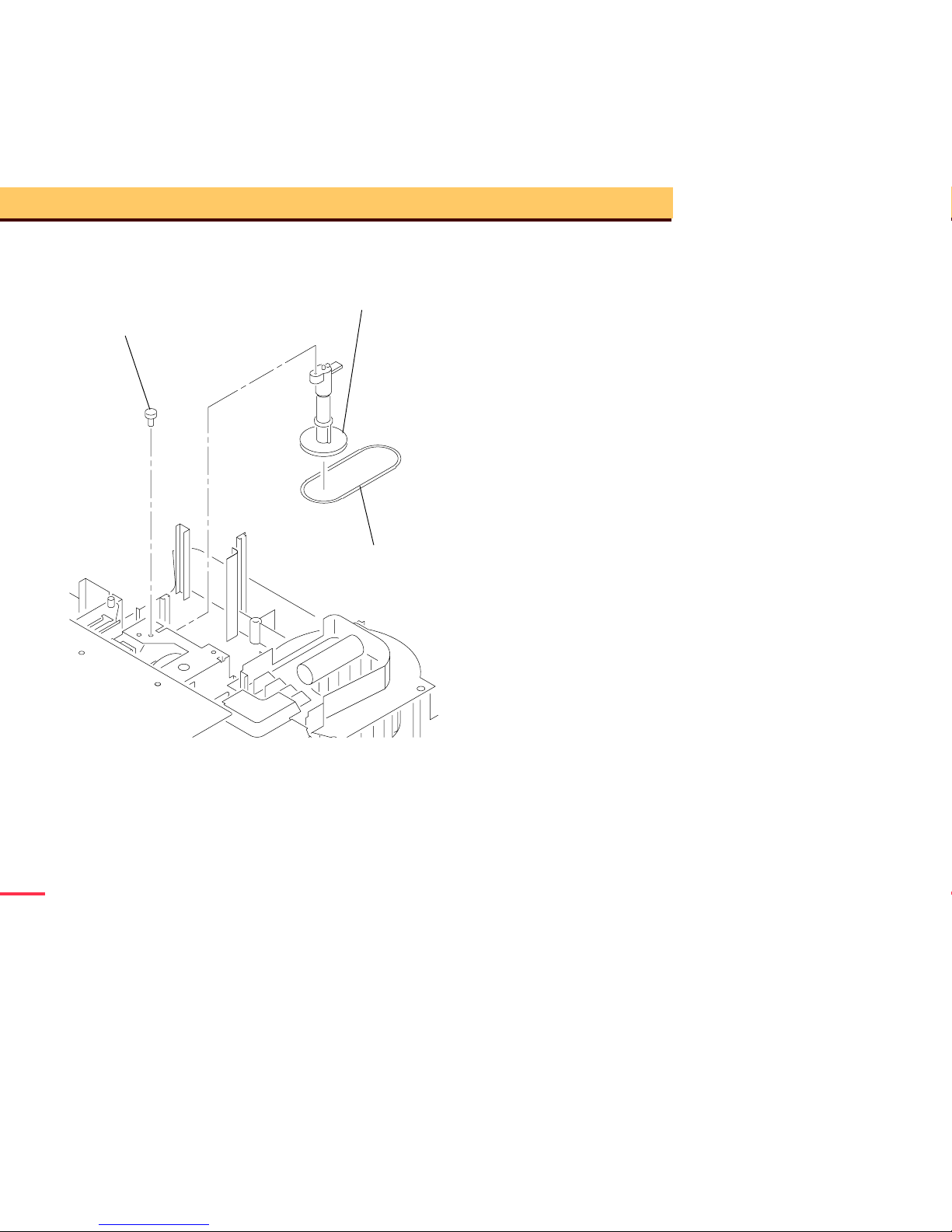
A091_0001HA
LAMP MODULE
A091_0001HCA
HOUSING
LOWER
Page 7

Page 8
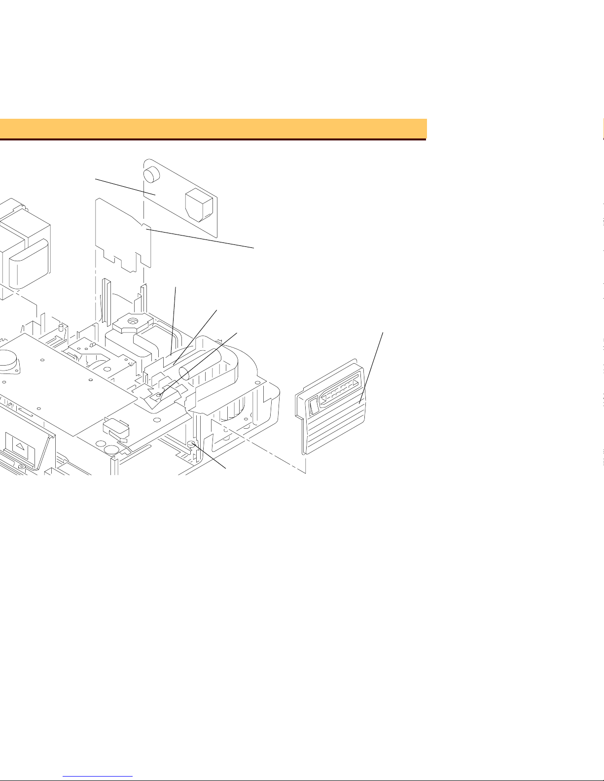
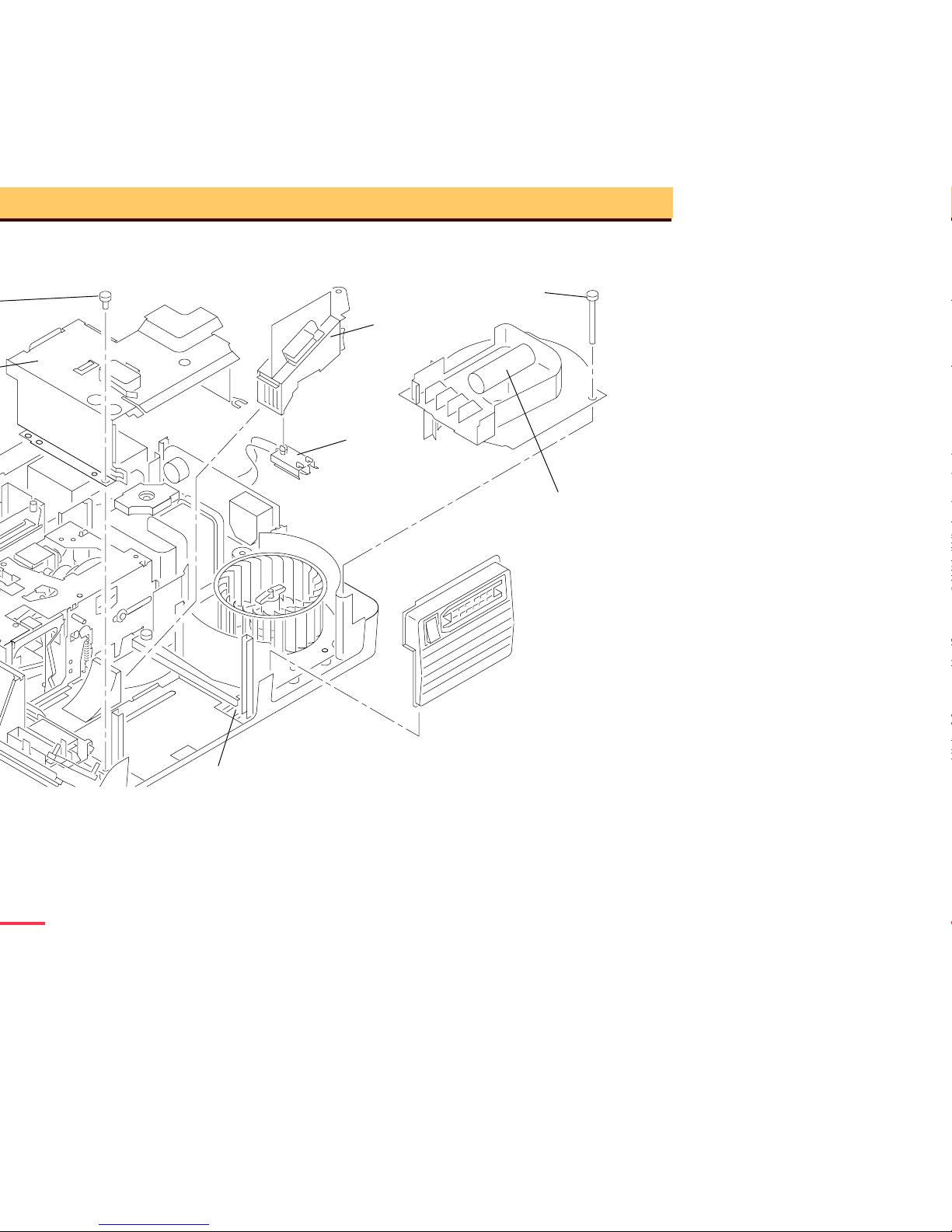
A091_4011HA
SCREW (not shown)
GRILLE
WIRE TIE
LOWER LIGHT
BLOWER COVER
(not shown)
WIRE TIE (2)
ASSEMBLY
A091_4011HCA
SCREW
BAFFLE TAB
POWER MODULE
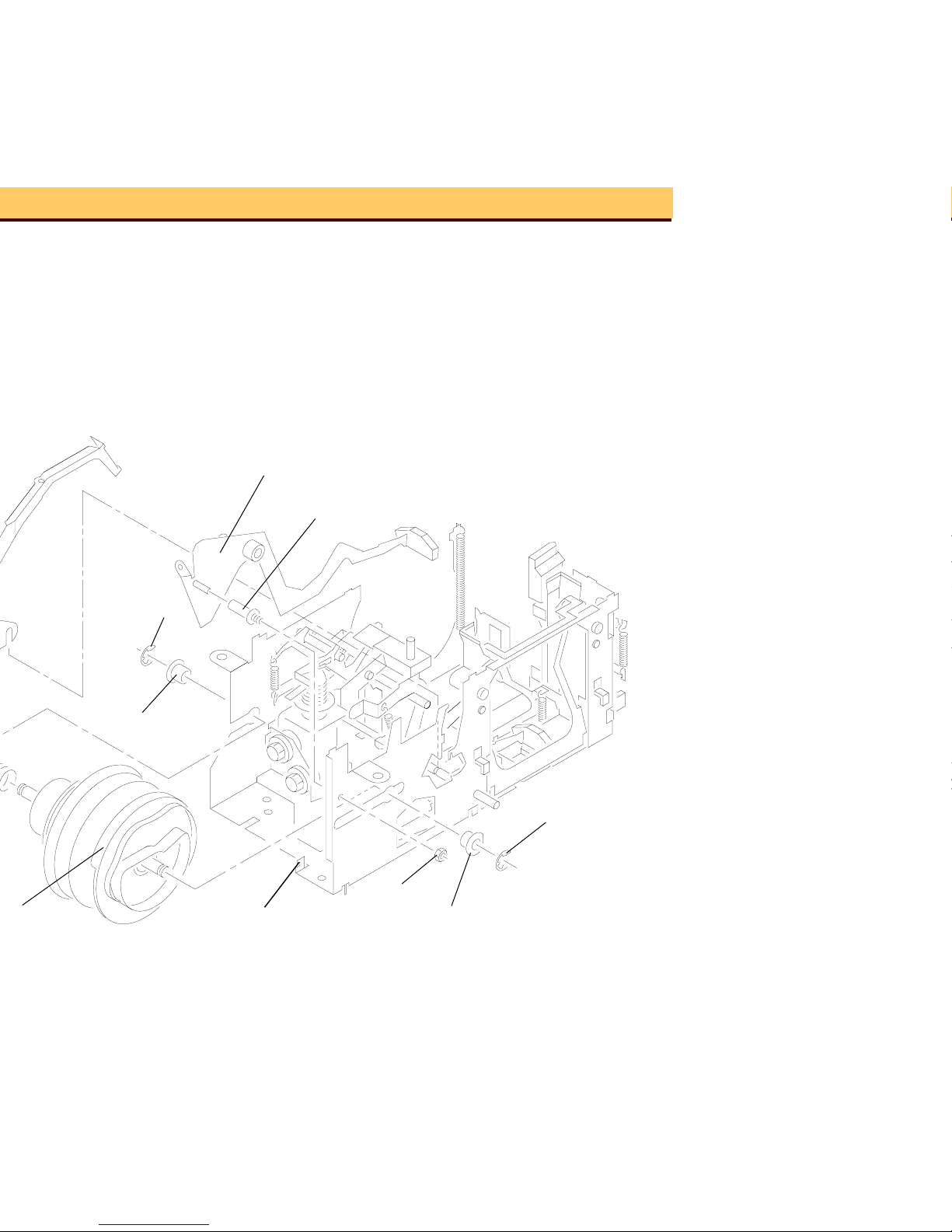
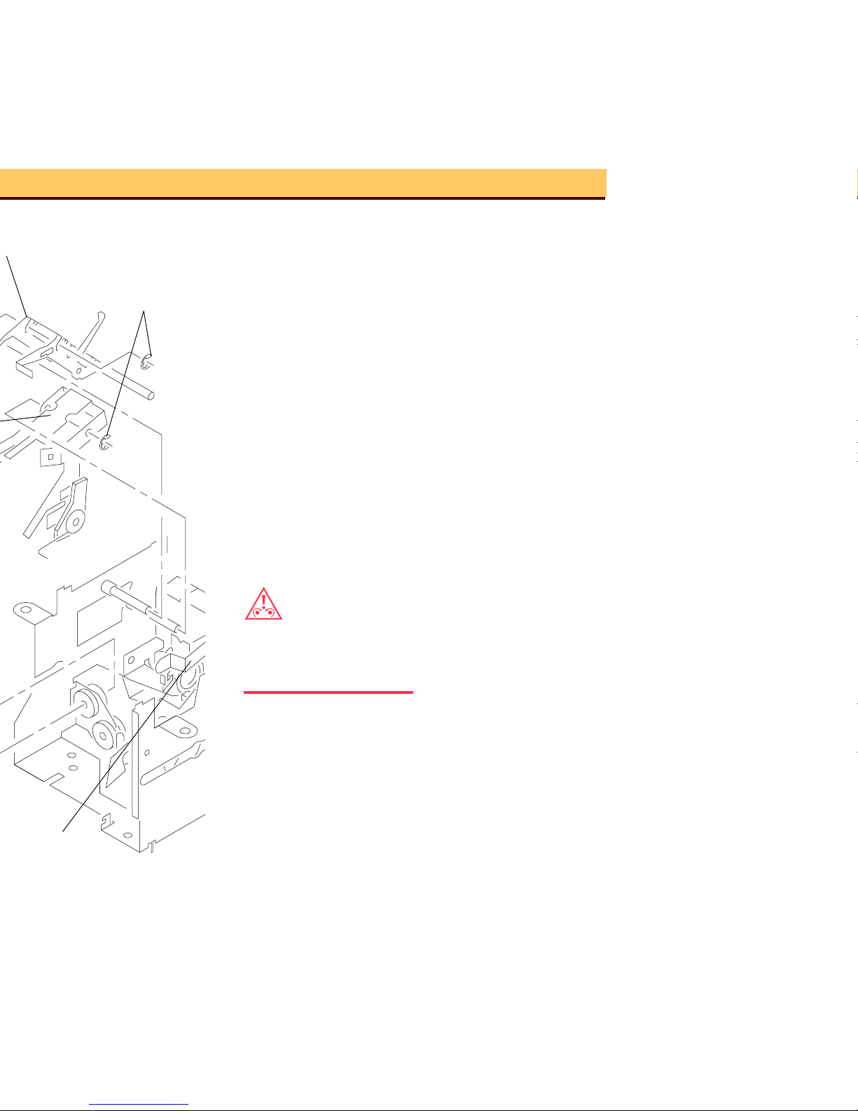
Page 9

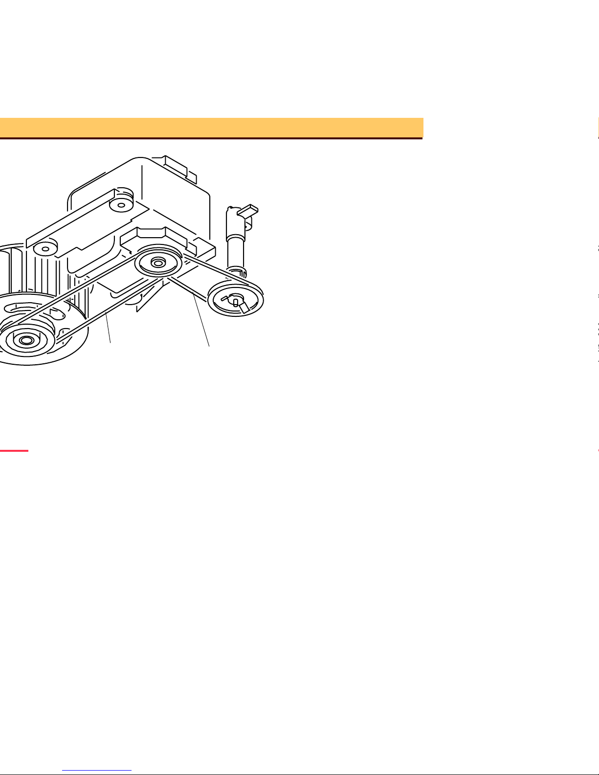
A091_4012HA
MECHANISM BELT
MOTOR
FAN BELT
SCREW
BLOWER
SCREW (3)
ASSEMBLY
FAN PLATE
A091_4012HCA
ASSEMBLY
RETAINER CLIP
FAN
SCREW (2)
Page 10
A091_4015BA
A091_4015BCA
MECHANISM BELT
FAN BELT
Page 11

Page 12
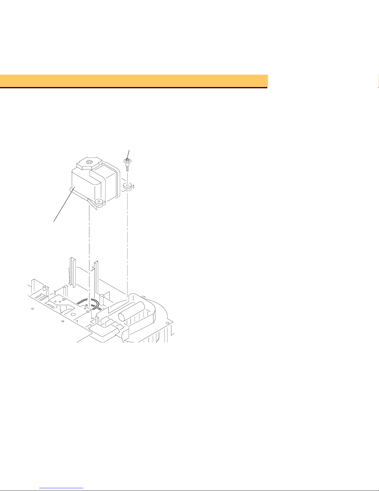
A091_4016GA
MOTOR
SCREW (3)
A091_4016GCA
Page 13
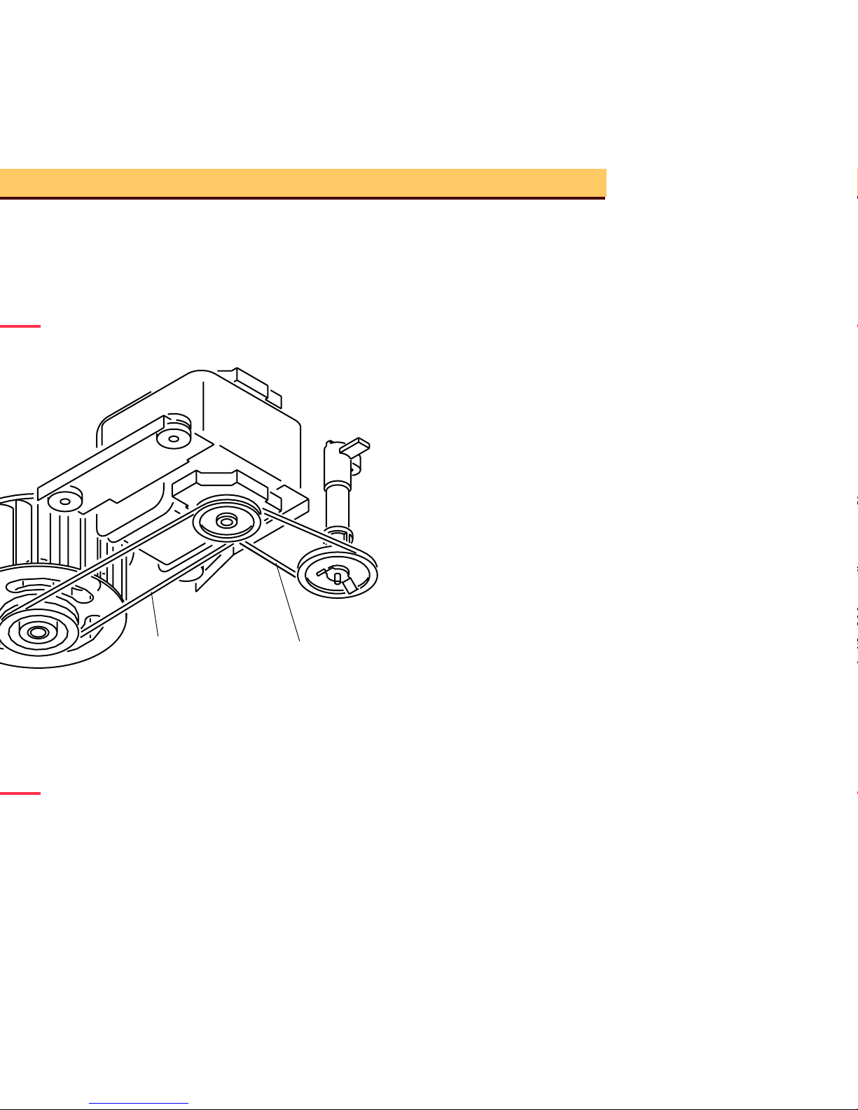
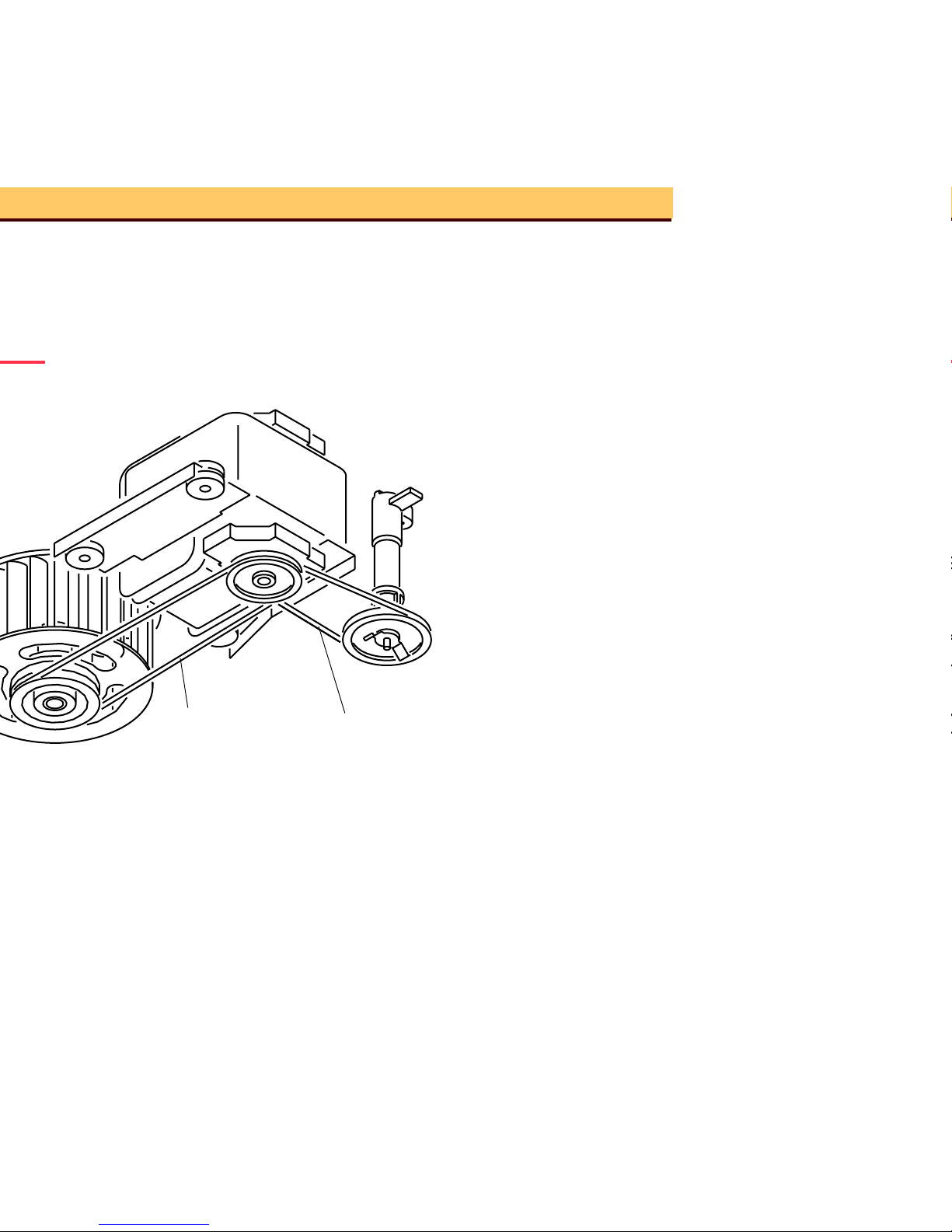
A091_4015BA
A091_4015BCA
MECHANISM BELT
FAN BELT
Page 14
A091_4017GA
WORM PULLEY
BELT
MECHANISM
A091_4017GCA
SCREW
Page 15
A091_4015BA
A091_4015BCA
MECHANISM BELT
FAN BELT
Page 16
A091_4018GA
(not shown)
SWITCH
INTERLOCK
PRE-HEAT
FUSE
THERMAL
A091_4018GCA
MAIN CIRCUIT BOARD
SWITCH
POWER
DUCT
SCREW
Page 17

Page 18
A091_4013HA
SCREW (not shown)
A091_4013HCA
ASSEMBLY
COVER
BLOWER
SCREW (2)
RECEPTACLE
MODULE
LAMP
DUCT
PRE-HEAT
Page 19
Warning
Dangerous Voltage
1 Disconnect the main power.
2 Do the removals for the LOWER
HOUSING ASSEMBLY and the
MOTOR.
3 Disconnect the 3 CONNECTORS on
the MAIN BOARD. It is not necessary to
disconnect the CONNECTORS next to
the LOWER LIGHT BAFFLE
ASSEMBLY.
4 Lift the MA IN BOARD up.
5 Cut and remove the necessary WIRE
TIES.
6 Disconnect t he 2 violet wires from the
CYCLE SOLENOID on the SMALL
BOARD.
7 Pull the SMALL BOARD up.
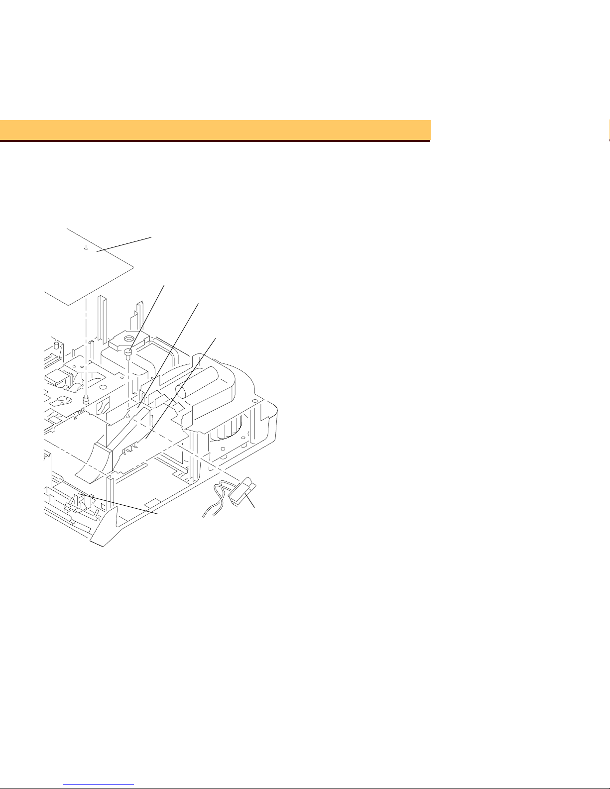
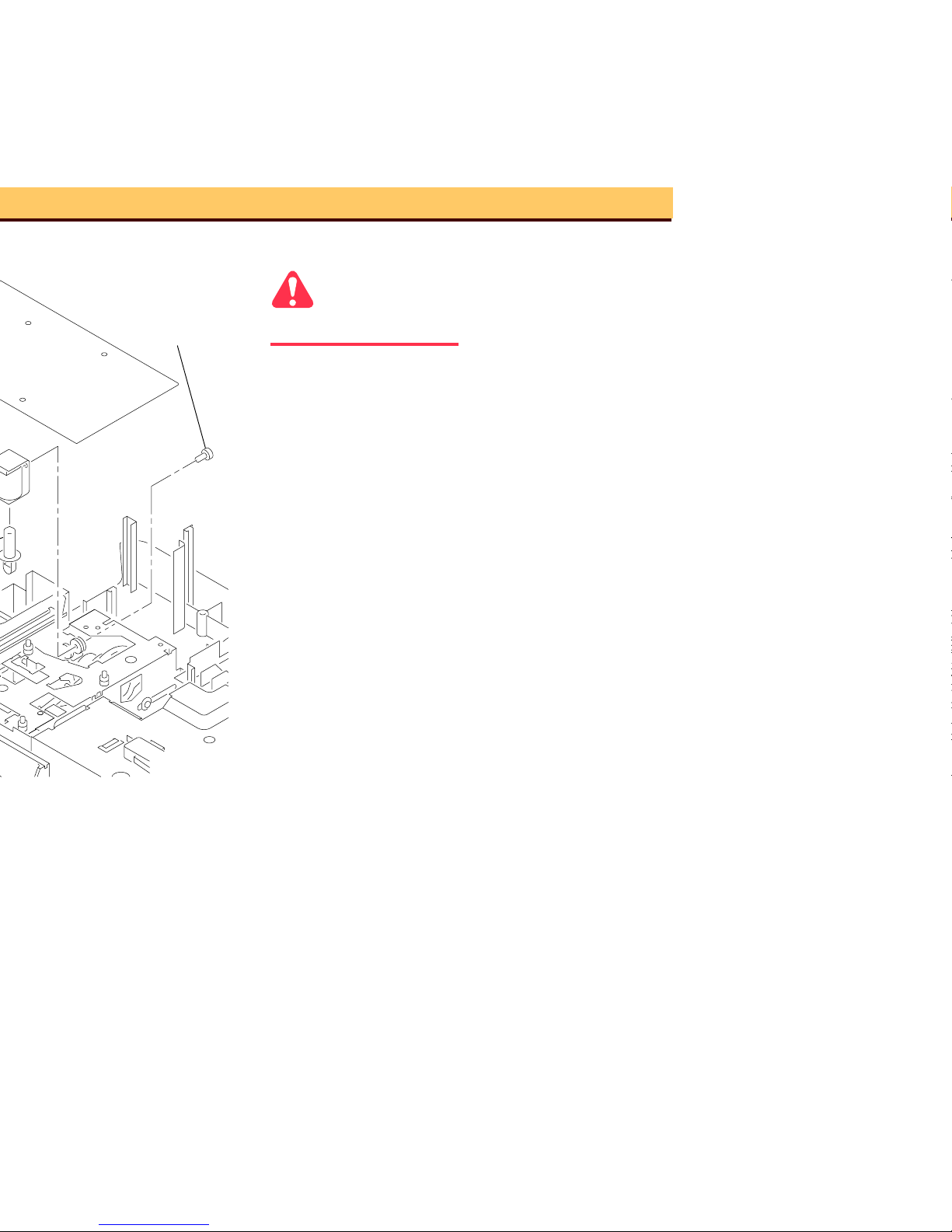
8 Remove the Torx SCREW from the
WORM PULLEY SHAFT.
9 Move the TAB on the WORM PULLEY
ASSEMBLY out of the MECHANISM
ASSEMBLY.
10 Lift and remove the WORM PULLEY
ASSEMBLY.
A091_4014GA
A091_4014GCA
SCREW (2)
Page 20

Page 21
Warning
Dangerous Voltage
1 Disconnect the main power.
Important
The Models Style 2 1500 and 2000 have a
DARK SHUTTER SWITCH and AUTO
FOCUS SHUTTER DEFEAT SWITCH.
2 Do the removal for the LOWER
HOUSING ASSEMBLY.
3 Disconnect the 3 CONNECTORS on
the MAIN BOARD. It is not necessary to
disconnect the CONNECTORS next to
the LOWER LIGHT BAFFLE
ASSEMBLY.
4 Lift the MA IN BOARD up.
5 Cut and remove the necessary WIRE
TIES.
6 Disconnect t he 2 violet wires from the
CYCLE SOLENOID on the SMALL
BOARD.
7 Pull the SMALL BOARD up.
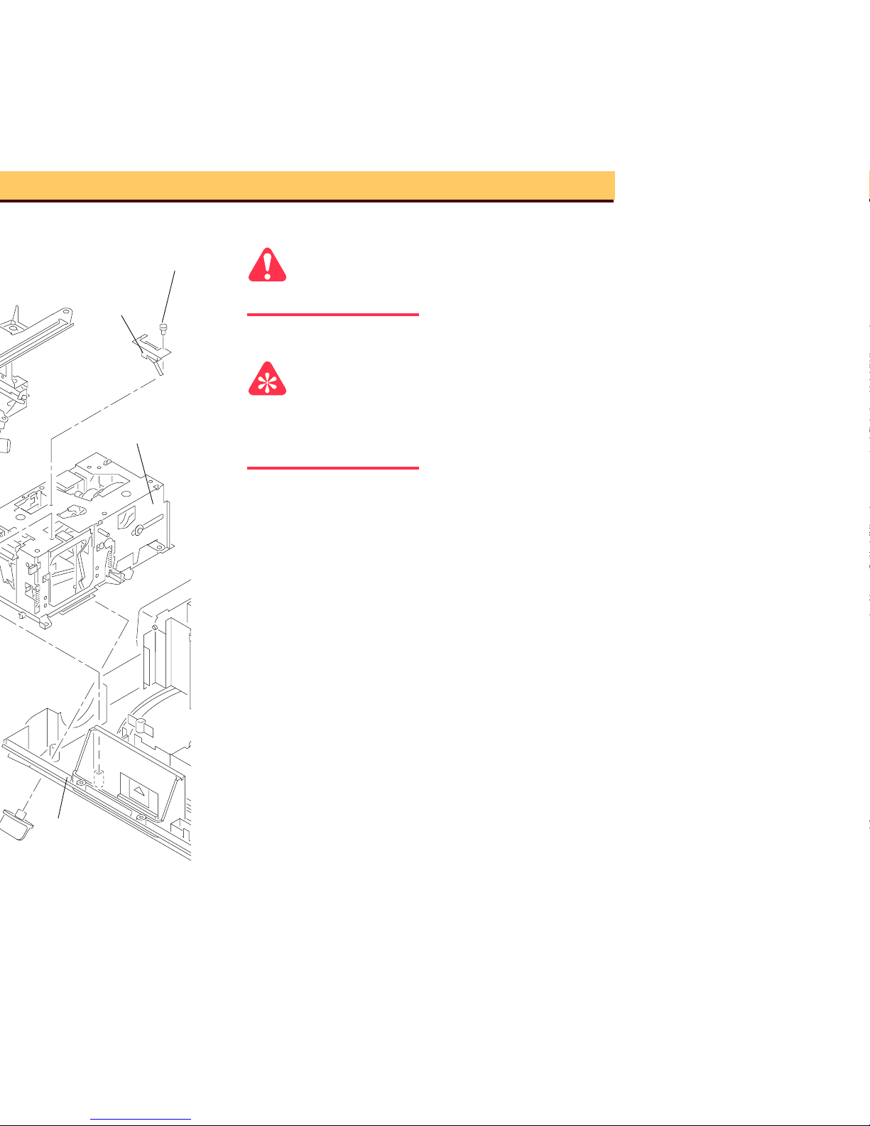
SWITCH
DARK
SHUTTER
ASSEMBLY
MECHANISM
(not shown)
DEFEAT SWITCH
AUTO FOCUS
SCREW (3)
SCREW
Page 22

Page 23

Page 24
A091_4023BA
ASSEMBLY
BRACKET
FOCUS
AUTO
SCREW (2)
SCREW
A091_4023BCA
PULLEY
WORM
Page 25

Page 26
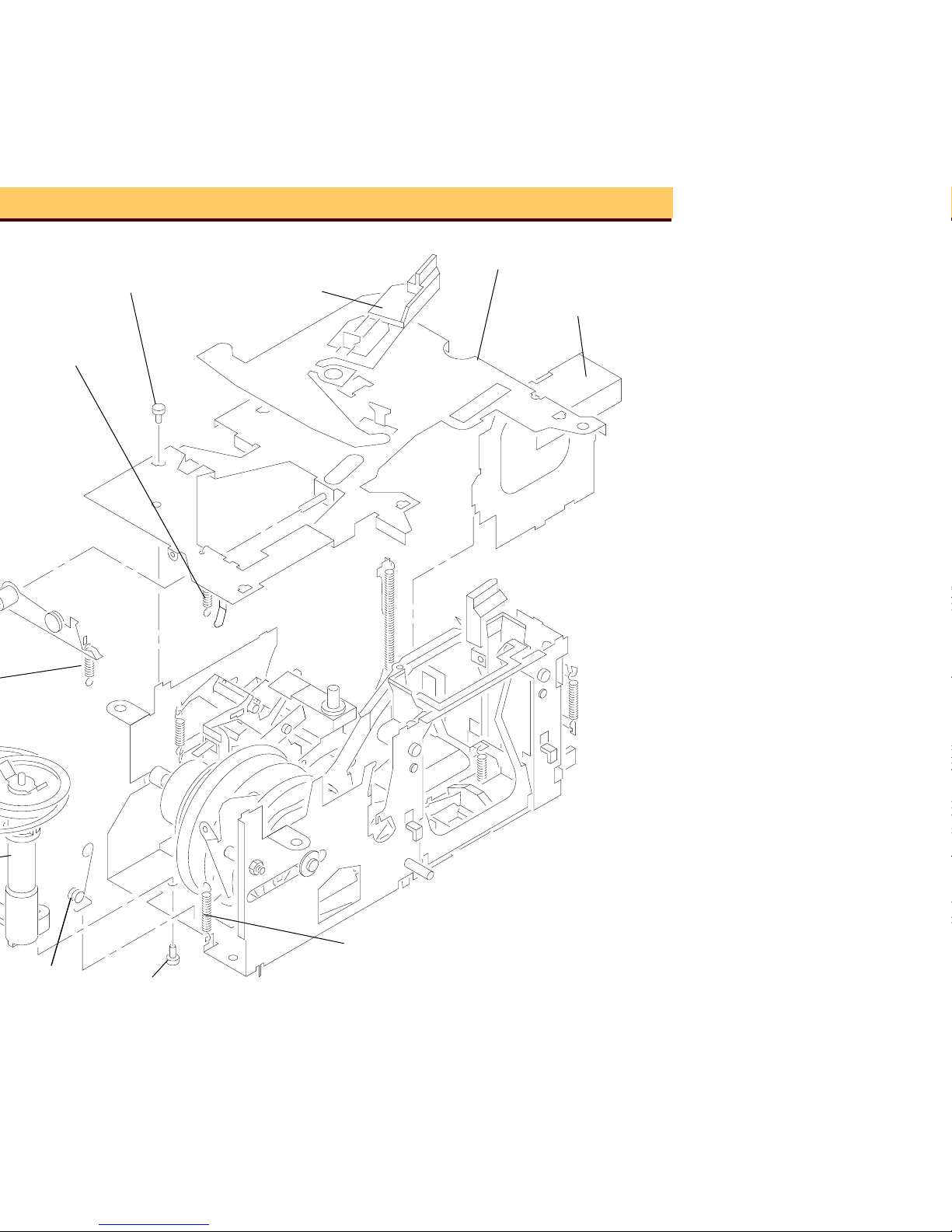
A091_0011DA
TOP LIGHT
BAFFLE
TOP PLATE
A091_0011DCA
SELECT LEVER SPRING
INDEXER
ASSEMBLY
LEVER
SCREW (7)
LIFT LEVER
SPRING
SCREW
Page 27
A091_0010HA
A091_0010HCA
TAB
LIFT
LEVER
BEARING
NUT
E-RING
E-RING
BEARING
LIFT LEVER SHAFT
Page 28
19 Remove the 2 SCREWS from the
CYCLE SOLENOID.
20 Remove the CYCLE SOLENOID.
21 Slide the PLUNGER a nd PLUNGER
SPRING off the CYCLE LEVER.
22 Remove the HALF CYCLE SPRING
between the CYCLE LEVER
ASSEMBLY and the HALF CYCLE
LEVER.
23 Disconnect the INDEX LEVER SPRING
from the MECHANISM ASSEMBLY.
24 Push the INDEX LEVER back.
25 Remove the 2 E-RINGS:
• 1 on the CYCLE LEVER ASSEMBLY
• 1 on the HALF CYCLE LEVER
Caution
Keep both the CYCLE LEVER ASSEMBLY
and the HALF CYCLE LEVER together and
observe the orientation of both LEVERS.
26 Slide both the CYCLE LEVER and
HALF CYCLE LEVER off the SHAFT.
A091_0009CA
and SPRING
INDEX LEVER
(not shown)
A091_0009CCA
E-RING (2)
Page 29

Page 30

Warning
Dangerous Voltage
1 Disconnect the main power.
Important
The EXTRA BRIGHT LAMP MODULE does
not have a HEAT ABSORBING GLASS and
has a LABEL on the LAMP DOOR.
2 Remove the LAMP MODULE.
3 Remove the PROJECTION LAMP from
the LAMP MODULE.
4 Remove the SCREW from the LAMP
DOOR PLATE ASSEMBLY.
A091_0018CA
LAMP DOOR
LAMP
LAMP
HEAT ABSORBING
PLATE ASSEMBLY
PROJECTOR
EJECTOR
ASSEMBLY
TERMINAL
LAMP SOCKET
GLASS
A091_0018CCA
LENS
CONDENSER
Page 31

Page 32

Warning
Dangerous Voltage
1 Disconnect the main power.
2 Do the removal for the LOWER
HOUSING ASSEMBLY.
3 Disconnect the 3 CONNECTORS on
the MAIN BOARD. It is not necessary to
disconnect the CONNECTOR next to
the LOWER LIGHT BAFFLE
ASSEMBLY.
4 Lift the MA IN BOARD up.
5 Remove the FOCUS KNOB.
6 Remove the shor t, gray wire connected
to the AUTO-FOCUS DEFEAT
SWITCH.
Important
It is necessary to push the AUTO-FOCUS
BRACKET backward and forward to allow
access to the SCREWS on the LENS
MOUNT ASSEMBLY.
7 Remove the 3 SCREWS from the LENS
MOUNT ASSEMBLY.
8 Lift and remove the LENS MOUNT
ASSEMBLY.
LENS
MOUNT
ASSEMBLY
SCREW (3)
Page 33

Warning
Dangerous Voltage
1 Disconnect the main power.
2 Do the removal for the LOWER
HOUSING ASSEMBLY.
3 Disconnect the 3 CONNECTORS on
the MAIN BOARD. It is not necessary to
disconnect the CONNECTOR next to
the LOWER LIGHT BAFFLE
ASSEMBLY.
4 Lift the MA IN BOARD up.
5 Remove the FOCUS KNOB.
6 Remove the 3 SCREWS from the LENS
MOUNT ASSEMBLY.
7 Lift and remove the LENS MOUNT
ASSEMBLY.
ASSEMBLY
MOUNT
LENS
Page 34

Warning
Dangerous Voltage
1 Disconnect the main power.
Important
There is no AUTO-FOCUS SWITCH
ASSEMBLY on the Models 500 and 1000.
2 Do the removal for the LOWER
HOUSING ASSEMBLY.
3 Disconnect the 3 CONNECTORS on
the MAIN BOARD. It is not necessary to
disconnect the CONNECTOR next to
the LOWER LIGHT BAFFLE
ASSEMBLY.
4 Lift the MA IN BOARD up.
5 Remove the FOCUS KNOB.
6 Remove the short, gray wire from the
AUTO-FOCUS DEFEAT SWITCH.
A091_4028GA
wires
and black
grey, red,
A091_4028GCA
Page 35

Page 36

Page 37

A091_4029HA
ASSEMBLY
AUTO-FOCUS
SWITCH
SPRING
CLAMP LEVER
LENS SUPPORT BRACKET
SCREW
A091_4029HCA
SOLENOID
PLUNGER
RACK
FOCUS SHAFT
SCREW
SPRING
SCREW
Page 38

Page 39

A091_0020HA
SCREW
BRACKET
LENS SUPPORT
SCREW
A091_0020HCA
FOCUS SHAFT
SPRING
Page 40

Page 41

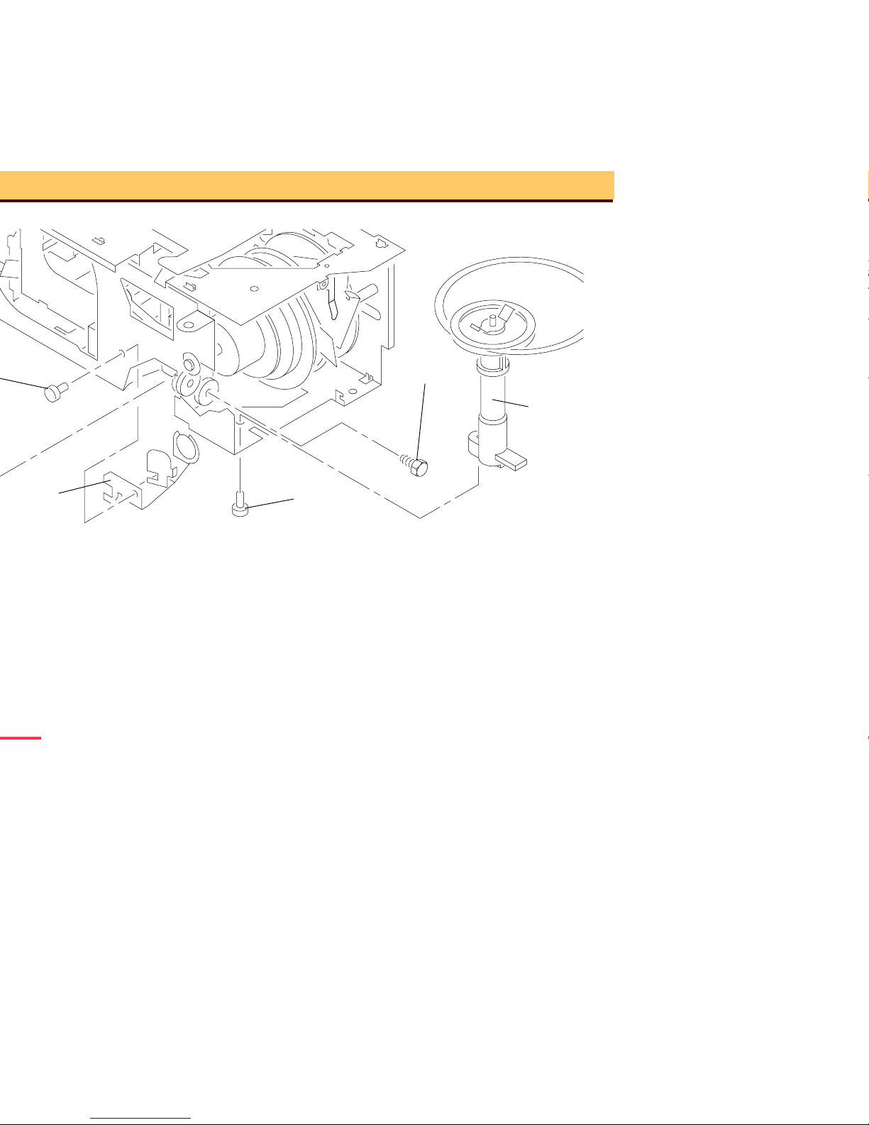
A091_0007HA
CYCLE
BAR
A091_0007HCA
ASSEMBLY
MECHANISM
Page 42

position 1 position 2
A091_0008HA
MECHANISM
ASSEMBLY
TOP PLATE
Bend
here.
A091_0008HCA
Page 43

A091_0016BA
SELECT
A091_0016BCA
(not shown)
LEVER
SLIDE LIFT
LEVER
Page 44

A091_0016BA
SELECT
A091_0016BCA
(not shown)
LEVER
SLIDE LIFT
LEVER
Page 45

Important
It is necessary use make a 5/16 in.
WRENCH to do this adjustment.
1 Energize the projector.
2 Connect the DIGITAL VOLT METER
(DVM) between PINS B5 and B6 of the
12 PIN APPLICATIONS PLUG.
3 With no TRAY installed, the DVM
should measure •.
4 Install a TRAY.
5 To move the TRAY out of the zero
position, press the “FORWARD” or
“REVERSE” BUTTONS; the DVM
should measure 0 W.
6
5
4
3
a
b
A091_4021AA
A091_4021ACA
Page 46

6 If the measur ements are not with in
specification, adjust the ZERO
POSITION SWITCH ECCENTRIC to
specification.
A091_0017GA
NUT
A091_0017GCA
SWITCH
ZERO POSITION
Page 47

Page 48

A091_4026HA
A091_4026HCA
Page 49

Page 50

TL-3002
TARGET SLIDE
AUTO-FOCUS
light path
NULL position
PAD
CLAMP LEVER
TAB
T-BAR
TL-3003
Page 51

Warning
Dangerous Voltage
1 Disconnect the main power.
2 Do the removal for the LOWER
HOUSING ASSEMBLY.
Important
It is necessary to use a FAN COVER TOOL.
3 Install the FAN COVER TOOL over the
FAN area and the LAMP MODULE.
4 Energize the projector.
5 Set the projector to the LO-LAMP
position.
6 Install and hold the AUTO FOCUS
TA RGET SLIDE TL-3002 until it is fully
seated in the GATE MECHANISM.
7 Look through the PROJECTION LENS
hole and observe the focus light path
on the AUTO-FOCUS TARGET SLIDE
TL-3002. Check that the light path is
correct. If not, do the adjustment for the
FOCUS LIGHT PATH.
A091_4032GA
CIRCUIT BOARD
PHOTOCELL
PHOTOCELL
HOUSING
A091_4032GCA
PHOTOCELL
MASK
FILTER (2)
wratten
Page 52

11 Install the FAN CAP 232729 in the
PHOTOCELL HOUSING.
A091_4033GA
A091_4033GCA
FAN CAP
Page 53

light path
PAD
CLAMP LEVER
TAB
NULL position
Page 54

A091_4030BA
T-BAR TL-3003
light image
FAN CAP
CLAMP PAD
ASSEMBLY
A091_4030BCA
hole
Page 55

Warning
Dangerous Voltage
1 Disconnect the main power.
2 Do the removal for the LOWER
HOUSING ASSEMBLY.
Important
It is necessary to use a FAN COVER TOOL.
3 Install the FAN COVER TOOL over the
FAN area and the LAMP MODULE.
4 Connect the REMOTE CONTROL
ASSEMBLY to the REMOTE
RECEPTACLE.
A091_4041GA
A091_4041GCA
Page 56

Page 57

A091_0013GA
SHUTTER
DARK
PAD
PRESSURE
A091_0013GCA
Page 58

Page 59

A091_4037GA
Page 60

A091_0021GA
Page 61

A091_0023HA
Page 62

A091_0022DA
Page 63

DIGITAL MULTIMETER
Page 64

11.5 cm
(4.5 in.)
A091_0024GA
TOOL
A091_0024GCA
COVER
FAN
Cut here.
Page 65

100, 115, 130, 220, 240 V, 50/60 HZ
TRAY
• Width: 238 mm (12.93 in.)
• Length: 295 mm (11.6 in.)
• The EXTRA BRIGHT MODULE
has a 30% increa se in lumen
output.
• EXR 82 V, 300 W, 35 hours
average life
• EXW 82 V, 300 W, 15 hours
average lamp life
• FHS 82 V, 300 W, 70 hours
average life
• EXY 82 V, 300 W, 200 hours
average life
Page 66

• Lowest corner t o center ratio is
55% minimum
• Te st met ho d
• Ektagraphic
• 102 mm, F/2.8 LENS aperture (24
x 36 mm), compatible with
European specification DIN 19027
low
• 49 × C (120 × F), 15% humidity in
high
• 21 - 27 × C (70 - 80 × F), 20 -
60% humidity op timum
BTUs of heat per hou r
specifications (TS 172)
specifications (TS 218)
Page 67

detachable
• Heat sensitive interrupt fuses
• 117 C ° LAMP THERMAL FUSE
• 169 C ° MOTOR THERMAL
FUSE
• 150 C ° TRANSFORMER
• SAFETY INTERLOCK SWITCH,
deenergizes projector when the
LAMP MODULE is removed.
maximum leakage current is 2.5 mA.
• Operates between th e following
times:
– Fast = 3 ± 1 second
– Slow = 22 ± 6 seconds
assembly.
Page 68

the auto-focus system will adjust
for the difference in the slide
position from slide to slide. This
focus adjustment will occur within
1 second after the slide is
inserted into the GATE.
• The focus adjustment variation
should not change from the focus
and reverse specifications by
more than 3 times the focus and
reverse specifications.
hours or 2,000,000 cycles. The
projector has a MTBF (mean time
between failures) of 7500 op eration
hours.
service person is r ecommended
every 1500 hours of operation, or
after 1 year.
Eastman Kodak Company to operate
correctly for one year from the date
of purchase.
Used for internal and external LAMP
control. The LAMP POWER SWITCH
must be set on either the LO/HI
position in th e “INT” position.
Page 69

• PIN 1 - Connected to PIN 3 =
Reverse
• PIN 2 - Connected to PIN 3 -
Forward
• PIN 3 - 25.5 V AC when used
with PIN 6
• PIN 4 - FOCUS MOTOR
• PIN 5 - FOCUS MOTOR
• PIN 6 - Used with PIN 3 for 25.5
V AC
• A1 - 25.5 V ac when c onnected to
B4
• A2 - No connection
• A3 - 25.5 V AC with a 2.7 K W
impedance load when used with
A4 (DISSOLVE CONTROL)
• A4 - Used with A3
• A5 - 24 V dc when co nnected to
B4
• A6 - SHUTTER SWITCH
• B1 - SHUTTER SWITCH
• B2 - When connected to B4 for
Reverse SLIDE TRAY
• B3 - When connected to B4 for
Forward SLIDE TRAY
• B5 - ZERO POSITION SWITCH
• B6 - ZERO POSITION SWITCH
Page 70

PIN Color
12
11
10
9
8
7
A091_0006BA
brown
white
black
84.2 V
1.6
117 V AC
6.1
LAMP VOLTAGE is
74 V AC
between brown
and white for
LONG LIFE MODELS
A091_0006BCA
Page 71

PIN Voltage
6
5
4
3
2
1
a
b
A091_4021AA
12-PIN APPLICATION PLUG
A091_4021ACA
Page 72

SWITCH
SWITCH
SWITCH
Page 73

PINS Voltage
1
2
3
A091_4036AA
A091_4036ACA
PHOTOCELL
Page 74

CABLE
CONNECTOR
1
2
3
4
5
6
GRAY
BLACK
FOCUS
1
2
3
46
5
S3
RED
YELLOW
25.5 VOLTS AC
LED
R1
2.7 K
GREEN
FWD
S2
A091_0001BA_
Page 75

A091_4034DC
J2
J1
SLIDE PROJECTOR BOARD
Q4
++
Q3
CR6
R15
R14
R13
R10
R11
R12
C2
C3
C4
R17
CR1
R5
R6
R4
Q1
CR3
C5
CR4
R7
F1
CR5
RYGNRWW
YBOVVARKWBW
Page 76

(-)
33.0 V dc
CR4 Red (+) 18.7 V dc
CR4 Black (-)18.7 V dc
Page 77

CR5
CR8
CR9
CR10
CR1
R 9
R 8
R 10
R 2
CR11
CR3
CR4
Q 4
R 4
CR7
CR6
R 7
U 2
R23
R27
R25
R11
R29
U 1
Q 9
C1
CR20
R26
CR17
CR16
R22
R13
Q 7
Q 8
Q 6
R21
R20
R18
R17
R19
Q 5
V101
C 3
VR1
R14
R15
R6
Q 2
CR2
Q 1
R16
C2
CR15
CR14
CR13
CR12
R12
R5
A091_4039DA
Q11
R28
F101
Page 78

MOTOR
INTERNAL setting
is a short•circuit at Q11,
the LAMP will stay on in
the EXT setting)
Page 79

FOCUS TRANSISTOR
(EBC - EMITTER, BASE, COLLECTOR)
(projector ON)
(reverse focus)
(projector ON)
(reverse focus)
(projector ON)
(forward focus)
(projector ON)
(forward focus)
BUTTON.
39 Ω, 18.7 V dc
Page 80

85-86 V ac without a
LAMP MODULE
installed
position.
3.0 Ω, 10.6 V ac drop
across
POWER FUSE, THERMAL
FUSE ASSEMBLY, and MOTOR
FUSE.
2. Check VARISTOR V101 on the
MAIN BOARD for damage.
VARISTOR V101 is damaged if
the voltage is not in the correct
position, for example, if the
voltage is set at 130 V when it
is necessary to operate at 240
V.
3. Check that the pr imary voltage
on the MAIN MOTOR is correct.
4. Check that the voltage on
POWER SWITCH is correct.
1. Check that the FAN BELT is not
broken.
2. Check and remove obstructions
in the FAN area.
Page 81

1. Check and remove obstructions
in the FAN area.
2. Check that the te nsion is c orrect
on the FAN BELT.
3. Check that the FAN BELT is
clean.
4. Check the condit ion of the
BEARING in the FAN
ASSEMBLY.
Page 82

1. Check the LAMP ASSEMBLY for
damage.
2. Check the LAMP RECEPTACLE
ASSEMBLY for damage.
3. Manually actuat e the
INTERLOCK SWITCH, then
check that the voltage is correct
across the LAMP RECEPTACLE
ASSEMBLY. If you do not
manually actuate the
INTERLOCK SWITCH, there will
be no voltage across the LAMP
RECEPTACLE ASSEMBLY.
4. Check that the voltage is corre ct
across the TRIAC on the MAIN
BOARD.
5. Check the LAMP TERMI NAL
ASSEMBLY in the LAMP
MODULE ASSEMBLY for
damage.
6. Check the “EXT/INT” SWITCH;
it should be in the “INT”
position.
• For 2000 PROJECTORS
Only: All THERMAL FUSES
and the LAMP MODULE
operate correctly.
Page 83

DROPPING RESISTOR is 3 W.
2. Check that the wire connections
on the POWER SWITCH are
correct.
3. Check the POWER SWITCH for
correct operation.
1. Check the DARK SHUTTER for
correct operation. See the
adjustment for the DARK
SHUTTER.
2. Check the LIGHT BAFFLE in
the MECHANISM for damage; it
should not cause a jam in the
SHUTTER.
Page 84

1. Check that the secondary voltage
on the MAIN MOTOR is correct.
2. Check that the voltage across the
CYCLE SOLENOID is correct.
3. Check that th e W across th e
CYCLE SOLENOID COIL are
correct.
1. Check that the CYCLE LEVER
and RATCHET PLATE are clean.
Clean and lubricate the parts as
necessary. Use SUPER LUBE TL-
4276.
2. Install a new CAM STACK
ASSEMBLY; the malfunction is
within the CAM.
1. Do the adjustment for the CYCLE
SOLENOID.
2. Check that the DIRECTION
LEVER SPRING is on the
DIRECTION LEVER.
3. Check the DIRECTION LEVER
for binds. Excessive lubrication
and dirt can cause binds.
Page 85

1. Check for a broken MECHANISM
DRIVE BELT.
2. Check the CYCLE LEVER and
RATCHET LEVER on the CAM
SHAFT ASSEMBLY for the
following:
• correct alignm ent of the
CYCLE LEVER
• damage to parts
• lubrication of the CYCLE
LEVER (use SU PER LUBE
TL-4276)
3. Check the CYCLE SOLENOID for
correct operation. See the Voltage
chart.
Page 86

correct alignment. See the
adjustment for the CYCLE
LEVER.
2. Check for damage to par ts.
3. Check for a shor t•circuit in the
wires:
• Use a tool to hold the CYCLE
LEVER down on the
RATCHET LEVER. If there is
a short•circuit causing the
malfunction, the SOLENOID
will be energized. If there is a
bind, the CAM will not rotate.
4. Check that the CAM SHAFT
ASSEMBLY RATCHET SPRING is
installed correctly.
The CYCLE LEVER and t he
RATCHET PLATE are d irty. Clean
and apply lubricant SUPER LUBE
TL-4276 to the CYCLE LEVER and
RATCHET PLATE. If this does not
correct the malfunction, install a new
CAM SHAFT ASSEMBLY.
Page 87

1. Check the SLIDE TRAY LATCH
for correct alignment.
2. Operate the pr ojector in the
forward direction.
• Check that the INDEXER
LEVER ASSEMBLY is in the
correct alignment with the
holes at positions A and B.
• Do the adjustment for the
INDEXER LEVER ASSEMBLY.
• Check the condition of the
LOCATOR LEVER, it should
not be bent.
• Check the height of the SLIDE
LIFT LEVER; the lower corner
of the LIFT LEVER LAMP is
parallel with the TOP
HOUSING. If the height is not
correct, do the adjustment for
the MANUAL and POWER
SLIDE LIFT LEVER
ECCENTRICS.
1. Do the adjustment for the CYCLE
SOLENOID.
2. Check for a bind in the
DIRECTION LEVER ASSEMBLY.
3. Check that the DIRECTION
LEVER LINK is in the correct
position.
Page 88

1. Press and release the SELECT
BUTTON.
• Check that the LOCATOR
LEVER moves correctly and is
not bent.
2. Press and hold the SELECT
BUTTON down.
• Check the SLIDE LIFT LEVER
RAMP for damage.
3. Check the height of the SLIDE
LIFT LEVER; the lower corner of
the LIFT LEVER LAMP is parallel
with the TOP HOUSING. If the
height is not correct, do the
adjustment for the MANUAL and
POWER SLIDE LIFT LEVER
ECCENTRICS.
1. Check the VARIABLE RESISTOR
for correct operation and inst all a
new part if necessary.
2. Move the TIMER BUTTON
forward and backward; use a
DVM to check for changes in W.
3. Energize the projector and move
the TIMER to “S”.
• Check the voltages on CR3,
Q3, and Q4, see the voltage
table.
Page 89

1. Energize the projector and
release the DARK SHUTTER to
allow projection.
2. Check for continuity between
PINS A6 and B1 on the 12-PIN
DISSOLVE PLUG.
3. Press the “FORWARD” or
“REVERSE” BUTTONS to close
the DARK SHUTTER.
4. In the closed position, the DVM
should measur e 0 W.
5. If this procedure does not correct
the malfunction, install a new
DARK SHUTTER SWITCH.
Page 90

1. De-energize the projector.
2. Check for continuity between PIN
B5 and B6 on the 12-PIN
DISSOLVE PLUG.
3. Install a SLIDE TRAY.
4. Rotate the SLIDE TRAY to
engage the ZERO POSITION
SWITCH, the DVM should
measure 0 W.
5. If the W measurement is not
correct, see the adjustment for the
ZERO POSITION SWITCH. Install
a new ZERO POSITION SWITCH
if necessary.
1. Remove R3 and install a new 68K
W 1/4 W RESISTOR (part
220040).
2. If there is still a malfunction,
install a new PHOTOCELL.
Page 91

SPRING for the correct tension.
2. Check the LENS SUPPORT
SPRING for correct tension.
3. Check the LENS DRIVE GEAR on
the FOCUS SHAFT ASSEMBLY
for damage and install a new part
if necessary.
1. Check the REMOTE CORD for
damage; use a REMOTE CORD
that has no damage.
2. Actuate and hold the REMOTE
CONTROL.
3. Check that the voltage across the
FOCUS MOTOR is correct.
4. Check that the secondary voltage
on the MAIN MOTOR is correct.
This condition will occur only when
the MAIN MOTOR is operating at the
same time you connect the REMOTE
CONTROL. It will not occur if the
MAIN MOTOR is not operating. This
is a normal condition; there is no
procedure to cor rect this condition.
Page 92

1. Check that the REMOTE CORD
operates correctly; use a
REMOTE CORD you know is
good.
2. Actuate and hold the REMOTE
CONTROL.
3. Check that the voltage across the
FOCUS MOTOR is correct.
4. Check the AUTO FOCUS
SWITCH ASSEMBLY for correct
operation.
5. Check the secondary voltages on
the MAIN MOTOR.
Page 93

1. Check that the AUTO-FOCUS
DEFEAT SWITCH is in the “ON”
position.
2. Check that the MAIN
PROJECTION LAMP operates
correctly.
3. Insert the TARGET SLIDE TL-
3002 in the GATE MECHANISM.
• Check that the TA RGET is
correctly aligned. If not, see
the Adjustment section.
4. Check that the voltages across the
PHOTOCELL are correct. The
voltage from 1 to 2 is 14.5 V ac.
The voltage from 2 to 3 is 14.5 V
ac. The voltage from 1 to 3 is 29
V ac.
5. Make a short• between 1 and 2;
the FOCUS MOTOR should rotate.
6. Make a short•circuit between 2
and 3; the FOCUS MOTOR
should rotate in the reverse
direction.
7. If the FOCUS MOTOR operates
correctly, install a new
PHOTOCELL. If the FOCUS
MOTOR does not op erate
correctly, measure the voltages on
the BOARD.
Page 94

1. Check that the alignment of the
FOCUS LIGHT PATH and NULL is
correct.
2. Check the resolution of the
FOCUS LIGHT PATH. Clean the
AUTO FOCUS MIRROR and
BRACKET ASSEMBLY.
3. Install a new PROJECTION LAMP
if necessary.
4. Install a new PHOTOCELL.
5. Check the components on the
BOARD for damage.
Page 95

1. Install the TARGET SLIDE TL-
3002 in the GATE MECHANISM.
2. Check that the alignment of the
TA RGET and NULL is correct. If
not, see the Adjustments section.
3. Check for a light leak:
• Install a different LAMP
MODULE ASSEMBLY. If the
FOCUS MOTOR stops
operating continually, install a
new LAMP MODULE
ASSEMBLY.
4. Check that the voltages across the
PHOTOCELL are correct. The
voltage from 1 to 2 is 14.5 V ac.
The voltage from 2 to 3 is 14.5 V
ac. The voltage from 1 to 3 is 29
V ac.
5. Check that the PHOTOCELL
HOUSING has 2 FILTERS.
6. Install a new PHOTOCELL.
7. Check the components on the
BOARD for damage.
Check that the wires of the AUTO
FOCUS MOTOR are in the correct
position; the blue wire goes to the
mark on the AUTO FOCUS MOTOR.
Do the adjustment for the CLAMP
LEVER ASSEMBLY.
Page 96

Kodak and Ektalite are trademark s.
 Loading...