

Page 1
{ServiceManual}{Produ ction}{KodakService Support}{Externa lAndInternal}
Important
SERVICE MANUAL
for the
Kodak EasyShare C140 DIGITAL CAMERA
Service Code: 8720
Kodak EasyShare CD14 DIGITAL CAMERA
Service Code: 9986
Qualified service personnel must repair this equipment.
Publication No. SM8720-1
15APR10
Supersedes SM8720-1
07JAN10
Confidential
Restricted Information
© EASTMAN KODAK COMPANY, 2010 KODAK SERVICE AND SUPPORT
Page 2

PLEASE NOTE The information contained herein is based on the experience and knowledge relating to the
This equipment includes parts and assemblies sensitive to damage from electrostatic
discharge. Use caution to prevent damage during all service procedures.
Description Page
subject matter gained by Eastman Kodak Company prior to publication.
No patent license is granted by this information.
Eastman Kodak Company reserves the right to change this information without notice, and
makes no warranty, express or implied, with respect to this information. Kodak shall not be liable
for any loss or damage, including consequential or special damages, resulting from any use of
this information, even if loss or damage is caused by Kodak’s negligence or other fault.
Table of Contents
Illustrated Parts List . . . . . . . . . . . . . . . . . . . . . . . . . . . . . . . . . . . . . . . . . . . . . . . . . . . . . . 4
Necessary Materials
Serial Numbers
Reference Table for New CAMERAS
Reference Table for Adjustment Procedures
Visual Index
Equipment Parts
COVER AYs, BATTERY DOOR AYs and LCD
MAIN BOARD and STROBE BOARD AY
LENS and FRAME AYs
Alphabetical Index
Diagnostics
Error Codes
Troubleshooting
LENS AY
LCD
LED
FLASH
MEMORY CARD
Power
Image Quality
Communication
General Functions
Diagnostic Tests
Checking the Date and Time Using the BACK-UP BATTERY
Checking the Power On “SelfAndKeytest”
Checking the “Video&TVTest” Functions
Checking for Uniform Flash
Checkout Procedures
Checking the General Functions of the CAMERA
Checking the Firmware Version, ACTUATION, FLASH, and POWER-ON
Checking the Communication and Audio Functions
Checking the External Components of the CAMERA
Adjustments
LENS AY, MAIN BOARD, STROBE BOARD AY - “Shutter Delay”
MASTER CAMERA - “Calibration of the MASTER CAMERA”
LENS AY, MAIN BOARD: CCD - “ISO_DBP_Shading”
LENS AY, MAIN BOARD: Auto Focus - “EFA”
2 15APR10 – SM8720-1
. . . . . . . . . . . . . . . . . . . . . . . . . . . . . . . . . . . . . . . . . . . . . . . . . . . . . . . . 8
. . . . . . . . . . . . . . . . . . . . . . . . . . . . . . . . . . . . . . . . . . . . . . . . . . . . . . . 15
. . . . . . . . . . . . . . . . . . . . . . . . . . . . . . . . . . . . . . . . . . . . . . . . . . . . . . . . . . . . . 16
. . . . . . . . . . . . . . . . . . . . . . . . . . . . . . . . . . . . . . . . . . . . . . . . . . . . . . . . 16
. . . . . . . . . . . . . . . . . . . . . . . . . . . . . . . . . . . . . . . . . . . . . . . . . . . . . . . . . . 16
. . . . . . . . . . . . . . . . . . . . . . . . . . . . . . . . . . . . . . . . . . . . . . . . . . . . . . . . . . 17
. . . . . . . . . . . . . . . . . . . . . . . . . . . . . . . . . . . . . . . . . . . . . . . . . . . . . . . . 17
. . . . . . . . . . . . . . . . . . . . . . . . . . . . . . . . . . . . . . . . . . . . . . . . . . . . . . . . . 18
COUNTERS . . . . . . . . . . . . . . . . . . . . . . . . . . . . . . . . . . . . . . . . . . . . . . . . . . 30
. . . . . . . . . . . . . . . . . . . . . . . . . . . . . . . . . . . . . . . . . . . . . . . . . . . . . . . . . . . . 32
. . . . . . . . . . . . . . . . . . . . . . . . . . . . . . . . . . . . . . . . . . . . . . . . . . 4
. . . . . . . . . . . . . . . . . . . . . . . . . . . . . . . . . . . . . . . . . . . . . . . . . . . . . 5
. . . . . . . . . . . . . . . . . . . . . . . . . . . . . . . . . . . . 6
. . . . . . . . . . . . . . . . . . . . . . . . . . . . . . . 7
. . . . . . . . . . . . . . . . . . . . . . . . . . . . . . . . . . . . . . . . . . . . . . . . . . . . . 9
. . . . . . . . . . . . . . . . . . . . . . . . . 9
. . . . . . . . . . . . . . . . . . . . . . . . . . . . . 11
. . . . . . . . . . . . . . . . . . . . . . . . . . . . . . . . . . . . . . . . . . . 13
. . . . . . . . . . . . . . . . . . . . . . . . . . . . . . . . . . . . . . . . . . . . . . . . . . . . . 16
. . . . . . . . . . . . . . . . . . . . . . . . . . . . . . . . . . . . . . . . . . . . . . . . . . . . . . 16
. . . . . . . . . . . . . . . . . . . . . . . . . . . . . . . . . . . . . . . . . . . . . . . . 18
. . . . . . . . . . . . . . . . . . . . . . . . . . . . . . . . . . . . . . . . . . . . . . . . . . . 19
. . . . . . . . . . . . . . . . . . . . . . . . . . . . . . . . . . . . . . . . . . . . . . . . . 19
. . . . . . . . . . . . . . . . . . . . . . . . . . . . . . . . . . . . . . . . . . . . . . . 20
. . . . . . . . . . . . . . . . . . . . . . . . . . . . . . . . . . . . . . . . . . . . . . . . . . . . . 21
. . . . . . . . . . . . . . 21
. . . . . . . . . . . . . . . . . . . . . . . . . . . . . 21
. . . . . . . . . . . . . . . . . . . . . . . . . . . . . . 22
. . . . . . . . . . . . . . . . . . . . . . . . . . . . . . . . . . . . . . . . 23
. . . . . . . . . . . . . . . . . . . . . . . . . . . . . . . . . . . . . . . . . . . . . . . . 26
. . . . . . . . . . . . . . . . . . . . . . . 26
. . . . . . . . . . . . . . . . . . . . . . 30
. . . . . . . . . . . . . . . . . . . . 31
. . . . . . . . . . . . . . 32
. . . . . . . . . . . . . . . . . . 34
. . . . . . . . . . . . . . . . . . . . . . . 36
. . . . . . . . . . . . . . . . . . . . . . . . . . . . . 38
Page 3

LENS AY, MAIN BOARD: CCD - “Run_In_WBP”. . . . . . . . . . . . . . . . . . . . . . . . . . . . 40
MAIN BOARD: Memory - “Reset”
MAIN BOARD, LCD - “Select LCD”
MAIN BOARD: Memory - “Serial Number”
Replacements
LCD
Additional Service Procedures
. . . . . . . . . . . . . . . . . . . . . . . . . . . . . . . . . . . . . . . . . . . . . . . . . . . . . . . . . . . 47
. . . . . . . . . . . . . . . . . . . . . . . . . . . . . . . . . . . . . . . . . . . . . . . . . . . . . . . . . . . . . . . 47
. . . . . . . . . . . . . . . . . . . . . . . . . . . . . . . . . . . . . . . . . . . . . . 49
Downloading the Files from the Partner Site
Installing the
Altek Vista SERVICE SOFTWARE on the Computer . . . . . . . . . . . . . . 50
Doing the Configuration of the SERVICE SOFTWARE
Checking the Connection to the SERVICE SOFTWARE
Preparing the MEMORY CARDS for Service
Preparing the “C140 Shutter_Delay” MEMORY CARD
Preparing the “C140 Master Camera” MEMORY CARD
Preparing the “C140 ISO_DBP_Shading” MEMORY CARD
Preparing the “C140 EFA” MEMORY CARD
Preparing the “C140 Run_In_WBP” MEMORY CARD
Preparing the “C140 Video&TVTest” MEMORY CARD
Preparing the “Select LCD” MEMORY CARD
Preparing the “C140 Self_Test” MEMORY CARD
Preparing the “C140 Reset” MEMORY CARD
Using the “HIDDEN MENU” of the CAMERA
Displaying the “HIDDEN MENU”
Checking for the Firmware Version and the Type of LCD
Upgrading the Firmware Using the MEMORY CARD
Diagrams
Publication History
. . . . . . . . . . . . . . . . . . . . . . . . . . . . . . . . . . . . . . . . . . . . . . . . . . . . . . . . . . . . . . 67
System Connections
Schematics
. . . . . . . . . . . . . . . . . . . . . . . . . . . . . . . . . . . . . . . . . . . . . . . . . . . . . . . . . 68
MAIN BOARD
STROBE BOARD
Component Layout
MAIN BOARD
STROBE BOARD
. . . . . . . . . . . . . . . . . . . . . . . . . . . . . . . . . . . . . . . . . . . . . . . . . . 67
. . . . . . . . . . . . . . . . . . . . . . . . . . . . . . . . . . . . . . . . . . . . . . . . . . . 68
. . . . . . . . . . . . . . . . . . . . . . . . . . . . . . . . . . . . . . . . . . . . . . . . 76
. . . . . . . . . . . . . . . . . . . . . . . . . . . . . . . . . . . . . . . . . . . . . . . . . . . 78
. . . . . . . . . . . . . . . . . . . . . . . . . . . . . . . . . . . . . . . . . . . . . . . . . . . 78
. . . . . . . . . . . . . . . . . . . . . . . . . . . . . . . . . . . . . . . . . . . . . . . . 80
. . . . . . . . . . . . . . . . . . . . . . . . . . . . . . . . . . . . . . . . . . . . . . . . . . . . . . . 81
. . . . . . . . . . . . . . . . . . . . . . . . . . . . . . . . . . . . . . . . 42
. . . . . . . . . . . . . . . . . . . . . . . . . . . . . . . . . . . . . . 44
. . . . . . . . . . . . . . . . . . . . . . . . . . . . . . . . . 45
. . . . . . . . . . . . . . . . . . . . . . . . . . . . . . . 49
. . . . . . . . . . . . . . . . . . . . . . . 56
. . . . . . . . . . . . . . . . . . . . . . 59
. . . . . . . . . . . . . . . . . . . . . . . . . . . . . . . 61
. . . . . . . . . . . . . . . . . . . 61
. . . . . . . . . . . . . . . . . . 61
. . . . . . . . . . . . . . . 62
. . . . . . . . . . . . . . . . . . . . . . . . . . . 62
. . . . . . . . . . . . . . . . . . . . 63
. . . . . . . . . . . . . . . . . . . 63
. . . . . . . . . . . . . . . . . . . . . . . . . . 63
. . . . . . . . . . . . . . . . . . . . . . . 64
. . . . . . . . . . . . . . . . . . . . . . . . . . 64
. . . . . . . . . . . . . . . . . . . . . . . . . . . . . . . 65
. . . . . . . . . . . . . . . . . . . . . . . . . . . . . . . . . . . . 65
. . . . . . . . . . . . . . . . . 65
. . . . . . . . . . . . . . . . . . . . . . . . . 66
SM8720-1 – 15APR10 3
Page 4

SERVICE MANUAL
Section 1: Illustrated Parts List
Necessary Materials
Primary Tools
Description Part No.
ESD MAT Region Provided
SCREWDRIVER - Phillips, No. 00 x 40 mm (1.57 in.) TL-5429
SCREWDRIVER - Phillips, No. 000 x 40 mm (1.57 in.) TL-5430
SCREWDRIVER - Phillips, No. 2 x 40 mm (1.57 in.) TL-5431
SCREWDRIVER - Phillips, No. 0 x 50 mm (1.97 in.) TL-5432
SCREWDRIVER - Milwaukee, cordless, with battery and charger, optional TL-5424
BATTERY for a POWER SCREWDRIVER - 2.4 V, optional TL-5422
HEX ADAPTER - 0.40 mm (0.02 in.) bit, optional TL-5421
BIT - power, 00 x 80 mm (3.14 in.), 4 mm (0.15 in.) drive, optional TL-5423
TWEEZERS - 2 TL-1207
TWEEZERS - special TL-5338
STATION - soldering, for solder with no Pb Region Provided
SOLDERING IRON - 35 W, 188 - 204
STATION - Weller, soldering, 50 W, optional TL-5412
TIP - soldering iron, standard ST1, optional TL-5413
TIP - soldering iron, single flat ST5, optional TL-5414
TIP - soldering iron, conical ST7, optional TL-5415
SOLDER REMOVAL TOOL Region Provided
FLASH CAPACITOR DISCHARGE TOOL - resistor minimum, 6.8 kΩ TL-5337
DIGITAL VOLTMETER TL-4114
DC POWER SUPPLY - 0 - 12 V, 5.0 A with clip leads, ez or alligator Region Provided
AIR HOSE - optional Region Provided
Kodak LENS CLEANING PAPER Region Provided
Kodak LENS CLEANER 1C8000
COVER CLEANER - Johnson SHINE-UP FURNITURE WAX TL-5182
Computer:
• Microsoft Windows XP OPERATING SYSTEM
• IBM COMPUTER or compatible, with a Pentium PROCESSOR, 2.0 GHz or higher
• 512 MB RAM
• 40 GB hard disk space
• CD-ROM DRIVE
• USB PORT
• 53 cm (21 in.) color MONITOR
• access to the INTERNET
Color VIDEO MONITOR Region Provided
FEEDBACK SOFTWARE Region Provided
LIGHT BOX - Arrowin LBF, 2001 Region Provided
LAMP - Arrowin LBF, 2001 light box, EVC/FGX, Phillips, 6958 Region Provided
0
C (370 - 4000F) TL-2818
Region Provided
4 15APR10 – SM8720-1
Page 5
Illustrated Parts List
Note
Description Part No.
PAINT - gray, 18%, interior flat Region Provided
Vendor:
RC Shaheen
1400 St. Paul Blvd.
Rochester, NY 14621
Telephone: 585-266-1500
MUR1597
TARGET - gray, 18%, with hook and loop tape TL-5931
GEN 3 CUSTOM TEST FIXTURE TL-5912
GEN 3 FIXTURE CAMERA PLATE - new, optional 4F9373
SHROUD - GEN 3 CUSTOM TEST FIXTURE - optional TL-5910
TRIPOD - Bogen, Model 3021s TL-5176
TRIPOD HEAD - Bogen, Model 3047 TL-5206
OPTRONICS PHOTOMETER/DETECTOR - Graseby Region Provided
COLOR TEMPERATURE METER - Gossen Color Pro 3F, or equivalent Region Provided
AUTO METER VF - Konica Minolta Region Provided
TAPE - masking Region Provided
Special Tools
Description Part No.
Kodak Ni-MH RECHARGEABLE DIGITAL CAMERA BATTERIES, AA, 2 122 3353
Kodak OXY-ALKALINE DIGITAL CAMERA BATTERY, AA, 2 892 2338
Kodak ALKALINE BATTERY Region Provided
USB CABLE, 8-pin, Model U-8, for Kodak EasyShare DIGITAL CAMERAS 3F9887
A/V CABLE, Model AV-8, 8-pin, for Kodak EasyShare DIGITAL CAMERAS 811 8390
SD, MMC or SDHC MEMORY CARD Region Provided
SERVICE SOFTWARE - “Vista for Service V4.1.1.4” *
Firmware file “kC140.fw”
If new firmware is released, the upgrade version is on the “Support Center” of the
Kodak.com Web Site.
Kodak EasyShare SOFTWARE, Version 5.0.2, 5.1, or 5.2 Region Provided
* This file is on the Kodak Partner Site.
Publications
Publication No. Title
XP9999-52 USER GUIDE for the GEN 3 CUSTOM TEST FIXTURE with T4
*
Serial Numbers
The configuration of the serial numbers is:
Description Serial Numbers
Kodak EasyShare C140 DIGITAL CAMERA • “KCGLE”
• “KBULE”
Kodak EasyShare CD14 DIGITAL CAMERA “KCGLM”
SM8720-1 – 15APR10 5
Page 6

SERVICE MANUAL
Reference Table for New CAMERAS
Use the following catalog numbers to order a replacement CAMERA if the CAMERA is under warranty and cannot
be repaired, or to order a MASTER CAMERA.
C140
Region Language Color Catalog or Part No.
Americas and Canada - SENSORMATIC and
CHECKPOINT TAGS
Europe, Africa, and the Middle East • English
Greater Asia • English
Kodak Service & Support - retail, class B English Silver-beige 113 6852
• English
•French
• Spanish
• Portuguese
•French
•German
•Dutch
• Italian
• Spanish
• Portuguese
• Russian
• Turkish
• Polish
•Greek
•Chinese,
simplified
• Korean
• Thai
Silver-beige 812 3119
Red 880 8453
Aqua 178 7712
Orange 814 5476
Silver-beige 846 4208
Red 168 0420
Aqua/Bundle 814 4693
Silver-beige 126 5545
Red 806 7092
Aqua/Bundle 842 2990
Red 161 9758
Aqua/Bundle 896 1815
Orange/Bundle 101 4109
CD14
Region Language Color Catalog or Part No.
Americas and Canada - SENSORMATIC and
CHECKPOINT TAGS
Kodak Service & Support - retail, class B English Silver-beige 112 9543
6 15APR10 – SM8720-1
• English
•French
• Spanish
• Portuguese
Silver-beige 197 6133
Red 117 5694
Silver 110 6244
Red 154 7348
Page 7

Illustrated Parts List
Reference Table for Adjustment Procedures
After installing: Do:
LENS AY or CCD • LENS AY, MAIN BOARD, STROBE BOARD AY - “Shutter Delay”
• LENS AY, MAIN BOARD: CCD - “ISO_DBP_Shading” on Page 36
• LENS AY, MAIN BOARD: Auto Focus - “EFA” on Page 38
• LENS AY, MAIN BOARD: CCD - “Run_In_WBP” on Page 40
MAIN BOARD • LENS AY, MAIN BOARD, STROBE BOARD AY - “Shutter Delay” on Page 32
• LENS AY, MAIN BOARD: CCD - “ISO_DBP_Shading” on Page 36
• LENS AY, MAIN BOARD: Auto Focus - “EFA” on Page 38
• LENS AY, MAIN BOARD: CCD - “Run_In_WBP” on Page 40
• MAIN BOARD: Memory - “Reset” on Page 42
• MAIN BOARD: Memory - “Serial Number” on Page 45
STROBE BOARD AY LENS AY, MAIN BOARD, STROBE BOARD AY - “Shutter Delay” on Page 32
on Page 32
SM8720-1 – 15APR10 7
Page 8
SERVICE MANUAL
P323 1001DC
1
2
3
1
P323_1001DCA
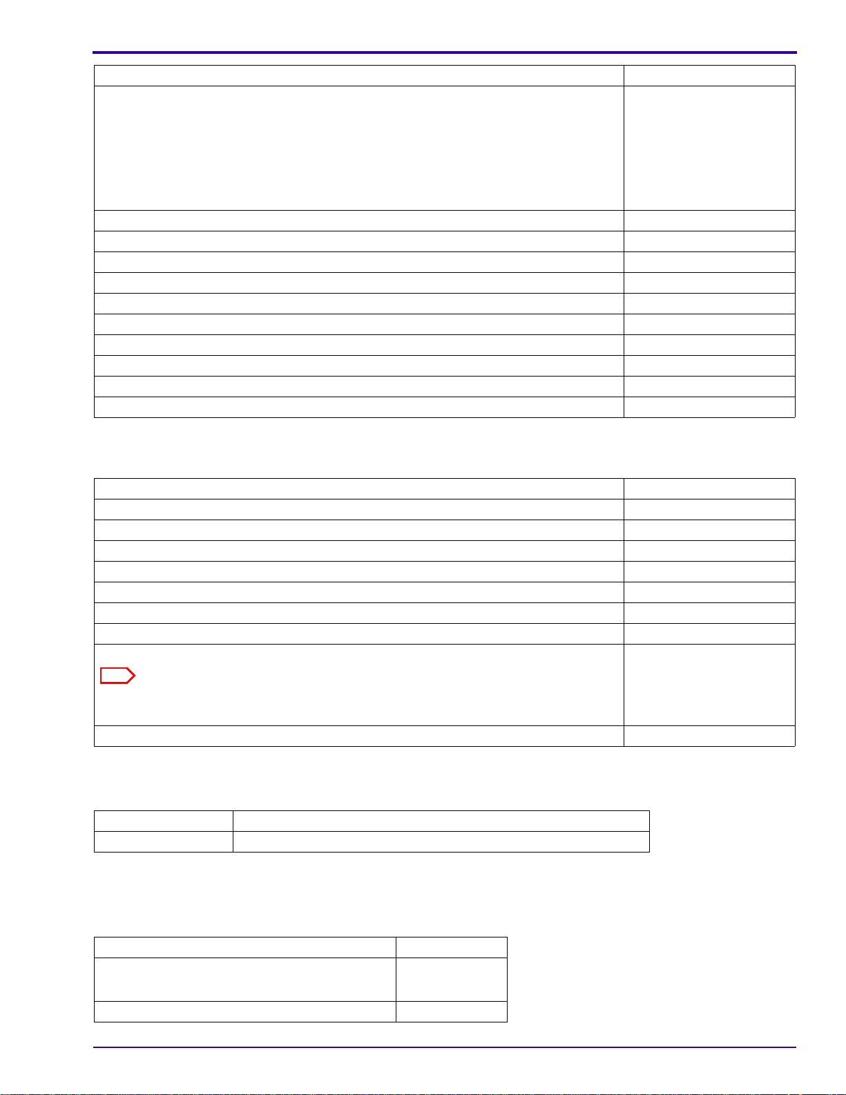
Visual Index
8 15APR10 – SM8720-1
Item Description
1 “
COVER AYs, BATTERY DOOR AYs and LCD” on Page 9
2 “MAIN BOARD and STROBE BOARD AY” on Page 11
3 “LENS and FRAME AYs” on Page 13
Page 9
Illustrated Parts List
Caution
P323_1002HC
P323_1002HCA
11
10
9
12
8
3
4
6
2
1
5
1
1
1
1
7
7
1
2
3
4
5
6
7
8
9
10
11
12
1
1
1
1
7
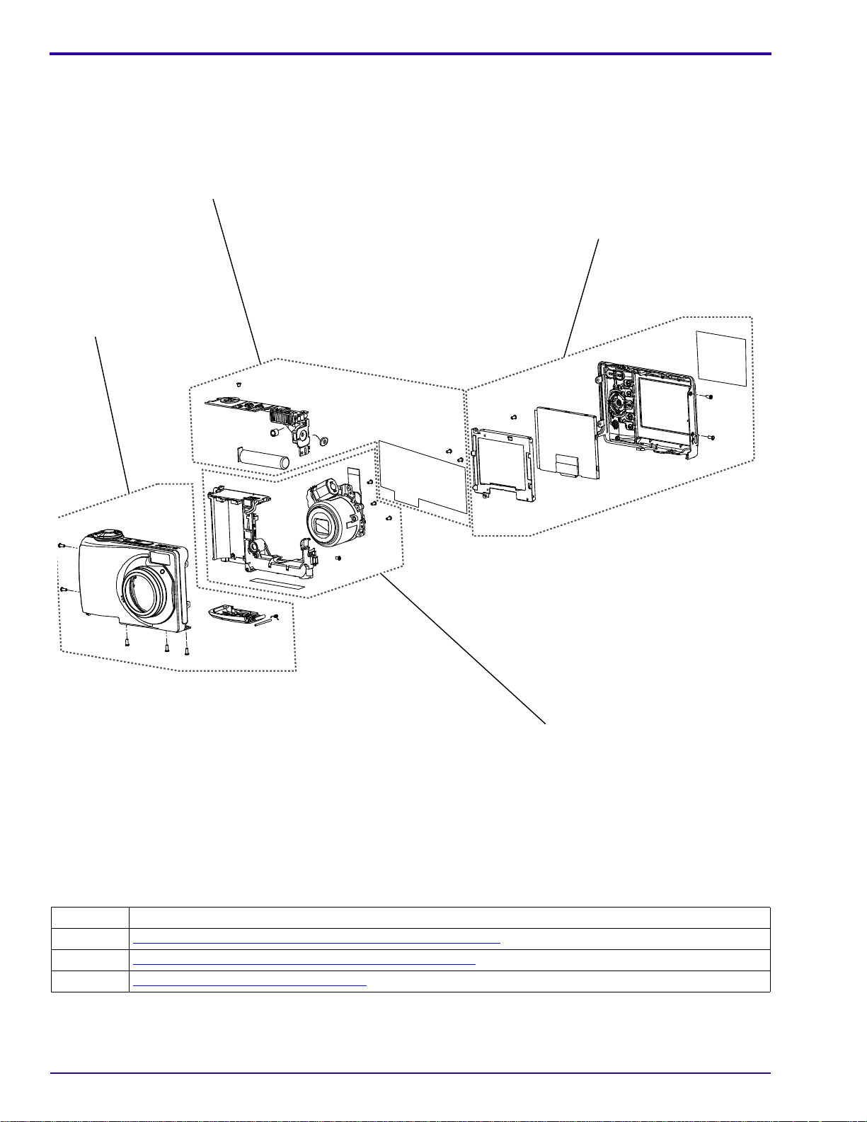
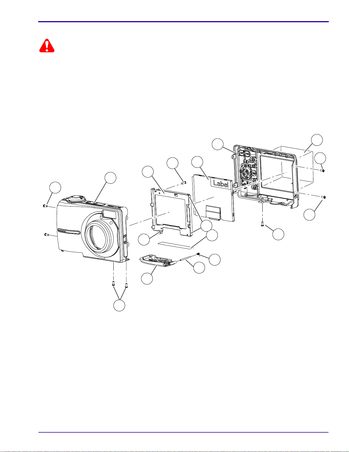
Equipment Parts
• Dangerous Voltage
• Before you remove the BACK COVER AY, you must remove, if installed:
– MEMORY CARD
– BATTERIES
• You must do a discharge of the STROBE CAPACITOR after you remove the FRONT COVER AY.
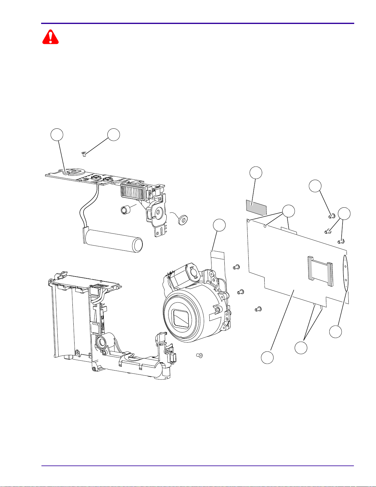
Figure 1 COVER AYs, BATTERY DOOR AYs and LCD
SM8720-1 – 15APR10 9
Page 10

SERVICE MANUAL
Figure 1 COVER AYs, BATTERY DOOR AYs and LCD
Item Part No. Description Quantity Notes
1 3F9937 SCREW - PH, TAP, 1.7 x 4.0 Ni
2 8H2131 COVER AY - front, silver-beige
8H2138 COVER AY - front, red
8H2141 COVER AY - front, aqua
8H2480 COVER AY - front, orange
8H2984 COVER AY - front, silver, CD14
3 8H2132 COVER AY - back, silver-beige, C140
8H2483 COVER AY - back, silver-beige, CD14
8H2139 COVER AY - back, red, C140
8H2484 COVER AY - back, red, CD14
8H2142 COVER AY - back, aqua, C140
8H2481 COVER AY - back, orange, C140
8H2985 COVER AY - back, black, CD14
4 8H2041 LCD - AUO, AO24CN02, 6.0 cm (2.36 in.)
5 2F6924 SCREW - PTP, TAP, 1.7 x 3.5, H = 0.6, black
6 4F8649 HOLDER - LCD
7 - - - - SOLDER JOINT
8 8H2144 FILM - protect, LCD
9 3F9936 SPRING - battery door
10 3F9935 HINGE - battery door
11 8H2133 DOOR AY - battery, silver-beige
8H2140 DOOR AY - battery, red
8H2143 DOOR AY - battery, aqua
8H2482 DOOR AY - battery, orange
8H2986 DOOR AY - battery, silver, CD14
12 8H2145 LABEL - power, silver-beige, C140
8H2485 LABEL - power, silver-beige, CD14
- - - - 3F9345 STRAP - wrist, black
1 7
1 1
1 1
1 1
1 1
1 1
1 1
1 1
1 1
1 1
1 1
1 1
1 1 Installs with the silver 8H2984.
1 1
1 1
1 1 See the “LCD” on Page 47.
1 3 For the LCD HOLDER.
1 1 You can also use 3F9938.
1 1
1 1
1 1
1 1
1 1
1 1
1 1 Installs with the silver 8H2984.
1 1
1 1
1 1 • Not visible in the graphic.
• You can also use 3F8616.
10 15APR10 – SM8720-1
Page 11
Illustrated Parts List
Caution
1
2
3
4
5
6
7
8
6
6
• Dangerous Voltage
• You must do a discharge of the STROBE CAPACITOR after you remove the FRONT COVER AY.
• For replacement of the MAIN BOARD, you must remove the CCD from the old MAIN BOARD and install the CCD
onto the new MAIN BOARD.
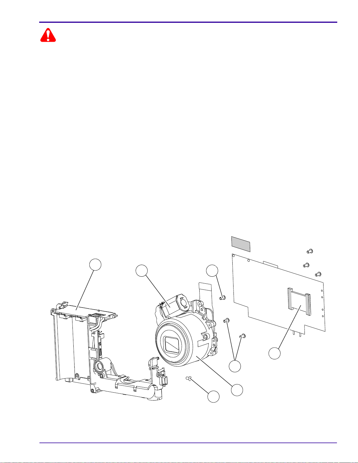
Figure 2 MAIN BOARD and STROBE BOARD AY
8
5
1
3
6
2
4
6
6
7
P323_1003DCA
P323_1003DC
SM8720-1 – 15APR10 11
Page 12

SERVICE MANUAL
Figure 2 MAIN BOARD and STROBE BOARD AY
Item Part No. Description Quantity Notes
1 - - - - TAPE - Mylar
2 - - - - FPC
3 2F6924 SCREW - PTP, TAP, 1.7 x 3.5, H = 0.6,
black
4 4F8595 SCREW - PH, TAP, 1.4 x 2.0, black
5 2F6923 SCREW - PTP, TAP, 1.7 x 2, 3.2 x 0.3, Ni
6 - - - - SOLDER JOINT
2 1 For the BATTERY CONTACTS.
2 1
6
2
2 2
2 1
2 19 • Between MAIN BOARD and
STROBE BOARD AY - 10
•Wires to:
– BATTERY CONTACTS - 3
– LED at the top left (green &
white) of the MAIN BOARD - 2
– BUZZER CABLE on the left
(red & black) of the MAIN
BOARD - 2
– MICROPHONE at the bottom
(yellow & blue) of the MAIN
BOARD - 2
7 8H2137 BOARD - main
8H2365 BOARD AY - main, GAR only
2 1
2 1 • Includes:
– MAIN BOARD
–CCD
– METAL PLATE
• Not in stock at this time.
8 8H2136 BOARD AY - strobe
- - - - 3F6205 FUSE - 2.5 A, F600
- - - - 3F6204 FUSE - 1.25 A, F800
2 1
2 2See “MAIN BOARD, Top” on Page 78.
2 2See “STROBE BOARD, Top” on
Page 80.
12 15APR10 – SM8720-1
Page 13
Illustrated Parts List
Caution
P323_1004HC
1
2
2
3
4
5
6
P323_1004HCA
1
2
3
4
5
6
2
• Dangerous Voltage
• You must do a discharge of the STROBE CAPACITOR after you remove the FRONT COVER AY.
• The LENS AY with the CCD also has a RUBBER BOOT and an UV-IR CUT FILTER that must remain with the
LENS AY.
• For replacement of the LENS AY only, you must:
– remove the new CCD from the new LENS AY
– use the old RUBBER BOOT and the old UV-IR CUT FILTER
– install the new LENS AY with the old CCD
• For replacement of the LENS AY and the CCD:
– remove the old CCD from the MAIN BOARD
– remove the new CCD from the LENS AY
– install the new CCD onto the MAIN BOARD
– install the new RUBBER BOOT, UV-IR CUT FILTER and LENS AY
• For replacement of the CCD only:
– remove the old CCD from the MAIN BOARD
– remove the new CCD from a new LENS AY
– install the new CCD onto the MAIN BOARD
• New CCDs and UV-IR CUT FILTERS are available for replacement parts.
Figure 3 LENS and FRAME AYs
SM8720-1 – 15APR10 13
Page 14

SERVICE MANUAL
Figure 3 LENS and FRAME AYs
Item Part No. Description Quantity Notes
1 2F6924 SCREW - PTP, TAP, 1.7 x 3.5, H = 0.6, black
2 3F9937 SCREW - PH, TAP, 1.7 x 4.0 Ni
3 8H2134 LENS AY - with CCD
8H2146 LENS AY - without CCD
4 8H2364 CCD
5 - - - - TAPE - Mylar
6 8H2135 FRAME AY
8H2366 FILTER - UV-IR cut
3 1
3 3 For the LENS AY.
3 1
3 1
3 1 Includes the METAL PLATE.
3 1 For the LENS MOTOR.
3 1
3 1 Not visible in the graphic.
14 15APR10 – SM8720-1
Page 15
Alphabetical Index
Section 2: Alphabetical Index
Alphabetical Index
Part No. Description Figure No.
8H2364 CCD 3
8H2137 BOARD - main 2
8H2365 BOARD AY - main, GAR only 2
8H2136 BOARD AY - strobe 2
8H2142 COVER AY - back, aqua, C140 1
8H2985 COVER AY - back, black, CD14 1
8H2481 COVER AY - back, orange, C140 1
8H2139 COVER AY - back, red, C140 1
8H2484 COVER AY - back, red, CD14 1
8H2132 COVER AY - back, silver-beige, C140 1
8H2483 COVER AY - back, silver-beige, CD14 1
8H2141 COVER AY - front, aqua 1
8H2480 COVER AY - front, orange 1
8H2138 COVER AY - front, red 1
8H2984 COVER AY - front, silver, CD14 1
8H2131 COVER AY - front, silver-beige 1
8H2143 DOOR AY - battery, aqua 1
8H2482 DOOR AY - battery, orange 1
8H2140 DOOR AY - battery, red 1
8H2986 DOOR AY - battery, silver, CD14 1
8H2133 DOOR AY - battery, silver-beige 1
8H2144 FILM - protect, LCD 1
8H2366 FILTER - UV-IR cut 3
- - - - FPC 2
8H2135 FRAME AY 3
3F6204 FUSE - 1.25 A, F800 2
3F6205 FUSE - 2.5 A, F600 2
3F9935 HINGE - battery door 1
4F8649 HOLDER - LCD 1
8H2145 LABEL - power, silver-beige, C140 1
8H2485 LABEL - power, silver-beige, CD14 1
8H2041 LCD - AUO, AO24CN02, 6.0 cm (2.36 in.) 1
8H2134 LENS AY - with CCD 3
8H2146 LENS AY - without CCD 3
4F8595 SCREW - PH, TAP, 1.4 x 2.0, black 2
3F9937 SCREW - PH, TAP, 1.7 x 4.0 Ni 1, 3
2F6923 SCREW - PTP, TAP, 1.7 x 2, 3.2 x 0.3, Ni 2
2F6924 SCREW - PTP, TAP, 1.7 x 3.5, H = 0.6, black 1, 2, 3
- - - - SOLDER JOINT 1, 2
3F9936 SPRING - battery door 1
3F9345 STRAP - wrist, black 1
- - - - TAPE - Mylar 2, 3
SM8720-1 – 15APR10 15
Page 16

SERVICE MANUAL
Section 3: Diagnostics
Error Codes
There are no error codes for this CAMERA.
Troubleshooting
LENS AY
Description Recommended Action
• The LENS does not retract or extend during
energizing or de-energizing.
• An error code displays during the zoom.
LCD
1. Check the FPC CABLE from the MOTOR to J500
CONNECTOR on the MAIN BOARD.
2. If necessary, do a replacement of:
• LENS AY
• MAIN BOARD
Description Recommended Action
The LCD does not energize. 1. Check the FPC from the LCD to CONNECTOR J400 on the
MAIN BOARD.
2. If necessary, do a replacement of:
•LCD
• MAIN BOARD
• The LCD energizes, but the screen is blank.
• Horizontal or vertical lines display on the
LCD.
• Malfunction of pixels occurs on the LCD.
The video function is not operating correctly. 1. Check:
1. Check:
• FPC from LCD to CONNECTOR J400 on the MAIN
BOARD
• SOLDER JOINTS of the CCD on the MAIN BOARD
2. If necessary, do a replacement of:
•LCD
• LENS AY
• MAIN BOARD
• FPC from LCD to CONNECTOR J400 on the MAIN
BOARD
• SOLDER JOINTS of the CCD on the MAIN BOARD
2. If necessary, do a replacement of:
•LCD
• MAIN BOARD
16 15APR10 – SM8720-1
Page 17

Diagnostics
LED
Description Recommended Action
The STATUS LED does not illuminate. 1. Check the SOLDER from the SHUTTER BOARD to the
MAIN BOARD.
2. If necessary, do a replacement of:
•LED
• MAIN BOARD
The SELF-TIMER LED does not operate
correctly.
1. Check the SOLDER of the LED CABLE on the MAIN
BOARD.
2. If necessary, do a replacement of:
•LED
• MAIN BOARD
FLASH
Description Recommended Action
The FLASH does not energize. 1. Check that the correct mode of the FLASH is selected.
2. Measure the voltage of the STROBE CAPACITOR across
both ends of the LAMP. The voltage should be > 300 V.
3. Check that the TRIGGER WIRE is soldered correctly.
4. If necessary, do a replacement of:
• SHUTTER BOARD
•FLASH LAMP
The FLASH operates in the “Fill Flash” mode,
but does not operate in the “Auto Flash” mode.
Smoke emits from the CAMERA when the
FLASH is actuated.
The LAMP for the FLASH is dark. 1. Check the connection of the metal PLATE between the
1. Check the brightness of the environment.
2. If necessary, do a replacement of the SHUTTER BOARD.
•Check:
– connection of the metal PLATE between the
CAPACITOR AY and the SHUTTER BOARD
– FLASH COVER or REFLECTOR AY has no debris
• If necessary, do a replacement of the SHUTTER BOARD.
FLASH AY and the SHUTTER BOARD.
2. If necessary, do a replacement of:
• CAPACITOR AY that includes the FLASH AY
• SHUTTER BOARD
SM8720-1 – 15APR10 17
Page 18

SERVICE MANUAL
MEMORY CARD
Description Recommended Action
The CAMERA does not recognize the MEMORY
CARD.
Images are not stored on the MEMORY CARD. 1. Use a new MEMORY CARD.
1. Use a new MEMORY CARD.
2. Check:
• “Image Storage” option is set to “Auto”
• SOCKET of the MEMORY CARD on the MAIN BOARD
has no damage
3. If necessary, do a replacement of the MAIN BOARD.
2. Check:
• position of the WRITE PROTECT SWITCH on the
MEMORY CARD
• “Image Storage” option is set to “Auto”
• SOCKET of the MEMORY CARD on the MAIN BOARD
has no damage
3. Format the MEMORY CARD and capture an image again.
4. If necessary, do a replacement of the MAIN BOARD.
Power
Description Recommended Action
The CAMERA does not energize. 1. Check:
• power source for the CAMERA
• SOLDER JOINTS of the BATTERY CONTACTS to the
• FUSE F600 on the MAIN BOARD. If necessary, install a
2. Diagnose the MODULE that has the malfunction.
• Disconnect all MODULES from the MAIN BOARD.
• Connect the MODULES one at a time, until the FUSE
3. If necessary, do a replacement of:
• MAIN BOARD
• SHUTTER BOARD
MAIN BOARD
new FUSE.
opens.
18 15APR10 – SM8720-1
Page 19

Image Quality
Description Recommended Action
The image on the LCD is not in focus. 1. Check:
• results of the “
• FPC CABLE from the MOTOR to J500 CONNECTOR
2. If necessary, do a replacement of:
• LENS AY
• MAIN BOARD
• The images are black.
• The color of the image is not correct.
• The images are too light.
• The images are too dark.
The images have pixels that are continually
energized.
1. Check the SOLDER JOINTS of the CCD on the MAIN
BOARD.
2. If necessary, do a replacement of:
• LENS AY
• MAIN BOARD
1. Check the results of the “
BOARD AY - “Shutter Delay”” on Page 32.
2. If necessary, do a replacement of:
• LENS AY
• MAIN BOARD
Do a replacement of the MAIN BOARD.
Diagnostics
LENS AY, MAIN BOARD: Auto Focus “EFA”” on Page 38 test are within the specification for
the CAMERA
on the MAIN BOARD
LENS AY, MAIN BOARD, STROBE
Communication
Description Recommended Action
The CAMERA does not download images from
the USB PORT.
1. Connect the CAMERA to the computer to check for
communication.
2. Check for damage to:
• USB CONNECTOR to the PINS on the J600 on the
MAIN BOARD
• USB PORT
3. If necessary, do a replacement of the MAIN BOARD.
SM8720-1 – 15APR10 19
Page 20

SERVICE MANUAL
General Functions
Description Recommended Action
One or more do not operate correctly:
• “Zoom” BUTTON
•“Delete” BUTTON
• “Menu” BUTTON
• “Info” BUTTON
• “Review” BUTTON
• 4-WAY BUTTON
• “OK” BUTTON
• “share” BUTTON
The SHUTTER BUTTON does not operate
correctly.
1. Check for damage to:
• BUTTONS
• UI PANEL AY inside the BACK COVER AY
• UI CIRCUIT on the MAIN BOARD
2. If necessary, do a replacement of the MAIN BOARD.
1. Check for damage to:
• BUTTONS
• SOLDER JOINTS from the SHUTTER BOARD to the
MAIN BOARD
2. If necessary, do a replacement of the SHUTTER BOARD.
20 15APR10 – SM8720-1
Page 21

Diagnostics
Note
Diagnostic Tests
Checking the Date and Time Using the BACK-UP BATTERY
[1] Insert RECHARGEABLE BATTERIES with a full charge into the CAMERA to apply 3.7 V to the BACK-UP
BATTERY or STORAGE CAPACITOR.
[2] Energize the CAMERA.
[3] Set the correct date and time.
[4] De-energize the CAMERA.
[5] Wait a minimum of 24 hours.
[6] Remove the RECHARGEABLE BATTERIES for more than 10 minutes.
[7] Insert the RECHARGEABLE BATTERIES into the CAMERA.
[8] Energize the CAMERA.
[9] Check the date and time.
The date and time must be correct within 30 seconds.
Checking the Power On “SelfAndKeytest”
[1] Do “Preparing the “C140 Self_Test” MEMORY CARD” on Page 64.
[2] Insert into the CAMERA:
• BATTERIES with a full charge
• “C140_Self_Test” MEMORY CARD
[3] Energize the CAMERA to execute the test.
[4] If the LCD displays “Set Date & Time”, select “Cancel”.
[5] Check:
• LCD displays “Script Loading...”
• results of each of the following tests
Test Check:
RBG and gray levels The quality of the 6 colors and the 6 gray areas
“LED testing” The red LED on the front of the CAMERA illuminates.
“LCD testing” LCD blinks
“Flash testing” STROBE energizes once
“SDRAM testing” “OK” displays
“LCD Bad pixel testing” LCD for:
• dark pixels in the white screen
• white pixels in the dark screen
“Temperature Sensor testing” “OK” displays
SWITCHES The names of the SWITCHES display on the LCD. Press each
SWITCH. A green “O” displays for each successful test.
[6] When the test is completed, follow the prompt to press the “OK” BUTTON.
[7] De-energize the CAMERA.
[8] Remove the MEMORY CARD.
SM8720-1 – 15APR10 21
Page 22

SERVICE MANUAL
Note
Note
Checking the “Video&TVTest” Functions
[1] Do “Preparing the “C140 Video&TVTest” MEMORY CARD” on Page 63.
[2] Insert into the CAMERA:
• BATTERIES with a full charge
• “C140 Video&TVTest” MEMORY CARD
[3] Energize the CAMERA.
[4] If the LCD displays “Set Date & Time”, select “Cancel”.
[5] Check that “Script Loading...” displays on the LCD.
The CAMERA records 4 seconds of video information automatically.
[6] When the LCD displays “Plug USB AV cable”, connect the A/V CABLE to:
• CAMERA
• TELEVISION
[7] Energize the TELEVISION.
[8] Check:
• LCD of the CAMERA de-energizes
• image is displayed on the TELEVISION
The test checks the video function automatically.
[9] Does the LCD display “Rec Fail”?
Yes No
a. Do Step 1
b. If the test is not successful again, install a new MAIN BOARD.
[10] Check the TELEVISION does:
• screen flashes once
• displays NTSC and PAL words
[11] Press the “OK” BUTTON.
[12] De-energize the CAMERA.
[13] Remove the MEMORY CARD from the CAMERA:
[14] Disconnect the A/V CABLE from:
• CAMERA
• TELEVISION
- Step 9 again.
Continue with Step 10.
22 15APR10 – SM8720-1
Page 23
Checking for Uniform Flash
Caution
• Dangerous Voltage
• A dark room or the GEN 3 CUSTOM TEST FIXTURE can be used.
• The distance is measured from the surface of the TARGET to the front surface of the CAMERA.
[1] Use either:
GEN 3 CUSTOM TEST FIXTURE
and new CAMERA PLATE, with
Controlled Light
a. If necessary, remove any DOCK
from the GEN 3 ADAPTER
PLATE.
b. Adjust the GEN 3 CUSTOM
TEST FIXTURE with:
• TARGET FRAME T3 to the
front
• HORIZONTAL MEASURE
TUBE “H” and “K” for T4
• VERTICAL MEASURE
TUBE “J” for T1
• “X” axis to 400
• “Y” axis to 990
c. Place:
• 18% gray TARGET in the
TARGET FRAME T4
• new GEN 3 FIXTURE
CAMERA PLATE on the
GEN 3 ADAPTER PLATE
• CAMERA on the new GEN
3 FIXTURE CAMERA
PLATE with the POST of
the CAMERA PLATE in the
TRIPOD MOUNT of the
CAMERA
d. Insert BATTERIES with a full
charge into the CAMERA.
e. Connect the USB CABLE to:
•CAMERA
•computer
f. Continue with Step 2
.
GEN 3 CUSTOM TEST FIXTURE
with Controlled Light Dark Room
a. If necessary, remove any DOCK
from the GEN 3 ADAPTER
PLATE.
b. Adjust the GEN 3 CUSTOM
TEST FIXTURE with:
• TARGET FRAME T3 to the
front
• HORIZONTAL MEASURE
TUBE “H” and “K” for T4
• VERTICAL MEASURE
TUBE “J” for T1
• “X” axis to 600
• “Y” axis to 690
c. Place:
• 18% gray TARGET in the
TARGET FRAME T4
• CAMERA on the GEN 3
ADAPTER PLATE with the
center POST of the
ADAPTER PLATE in the
TRIPOD MOUNT of the
CAMERA
d. Insert BATTERIES with a full
charge into the CAMERA.
e. Connect the USB CABLE to:
• CAMERA
•computer
f. Continue with Step 2
.
a. Insert BATTERIES with a full
charge into the CAMERA.
b. Connect the USB CABLE to:
•CAMERA
•computer
c. Place:
• CAMERA on the
TRIPOD or flat surface
• TARGET 1.0 m (39.4 in.)
from the front surface of
the CAMERA
d. Continue with Step 2
Diagnostics
.
SM8720-1 – 15APR10 23
Page 24
SERVICE MANUAL
Note
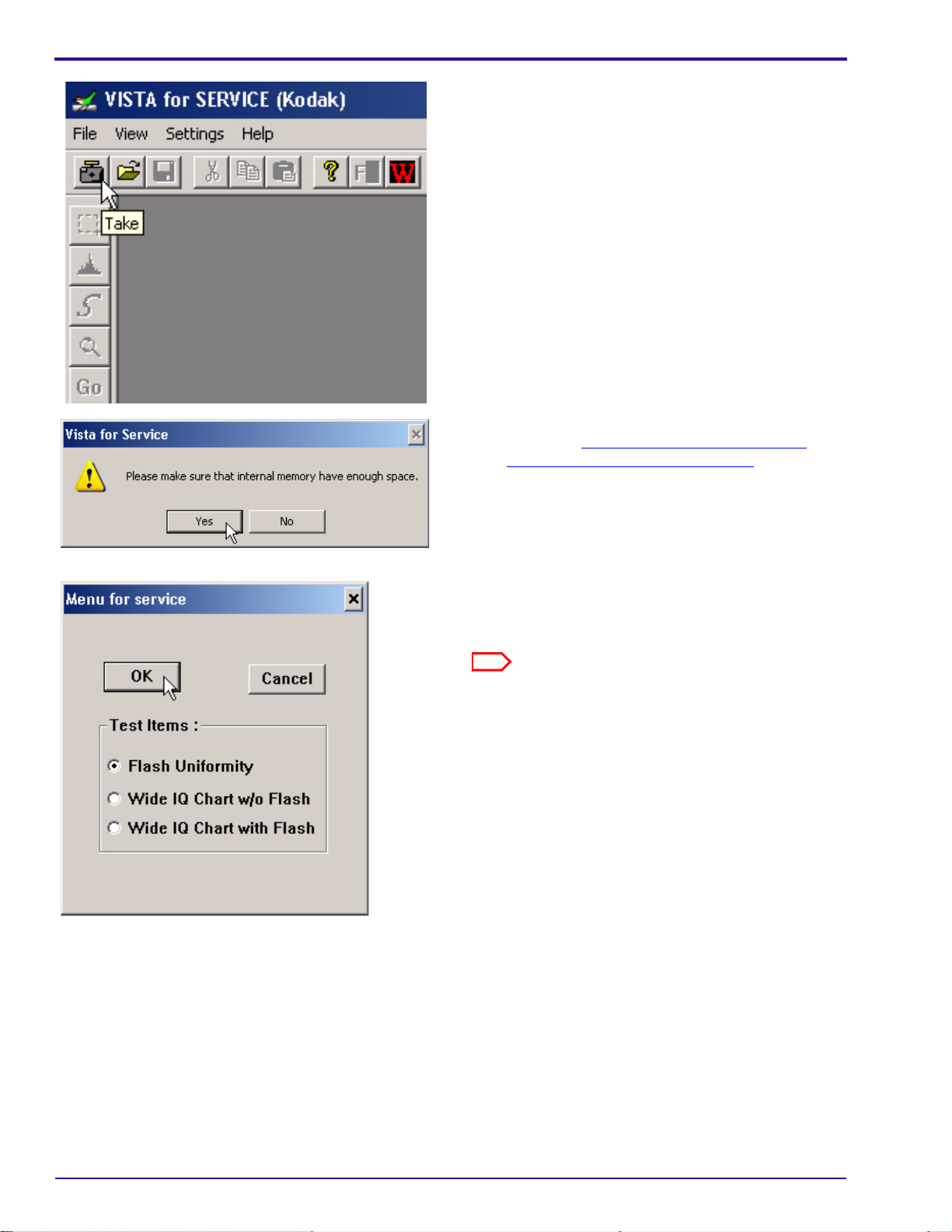
[2] Double-click the “Vista for Service” icon.
[3] At the same time, press and hold:
• “Tele” BUTTON
• “Review” BUTTON
• “On/Off” BUTTON
[4] Release the BUTTONS to energize the CAMERA.
[5] Click:
•“Take” icon
•[Yes]
[6] If a communication error displays, see the
procedure “
Checking the Connection to the
SERVICE SOFTWARE” on Page 59.
[7] Close the GEN 3 CUSTOM TEST FIXTURE.
[8] Select “Flash Uniformity”.
[9] Click [OK].
The flash actuates once.
24 15APR10 – SM8720-1
Page 25
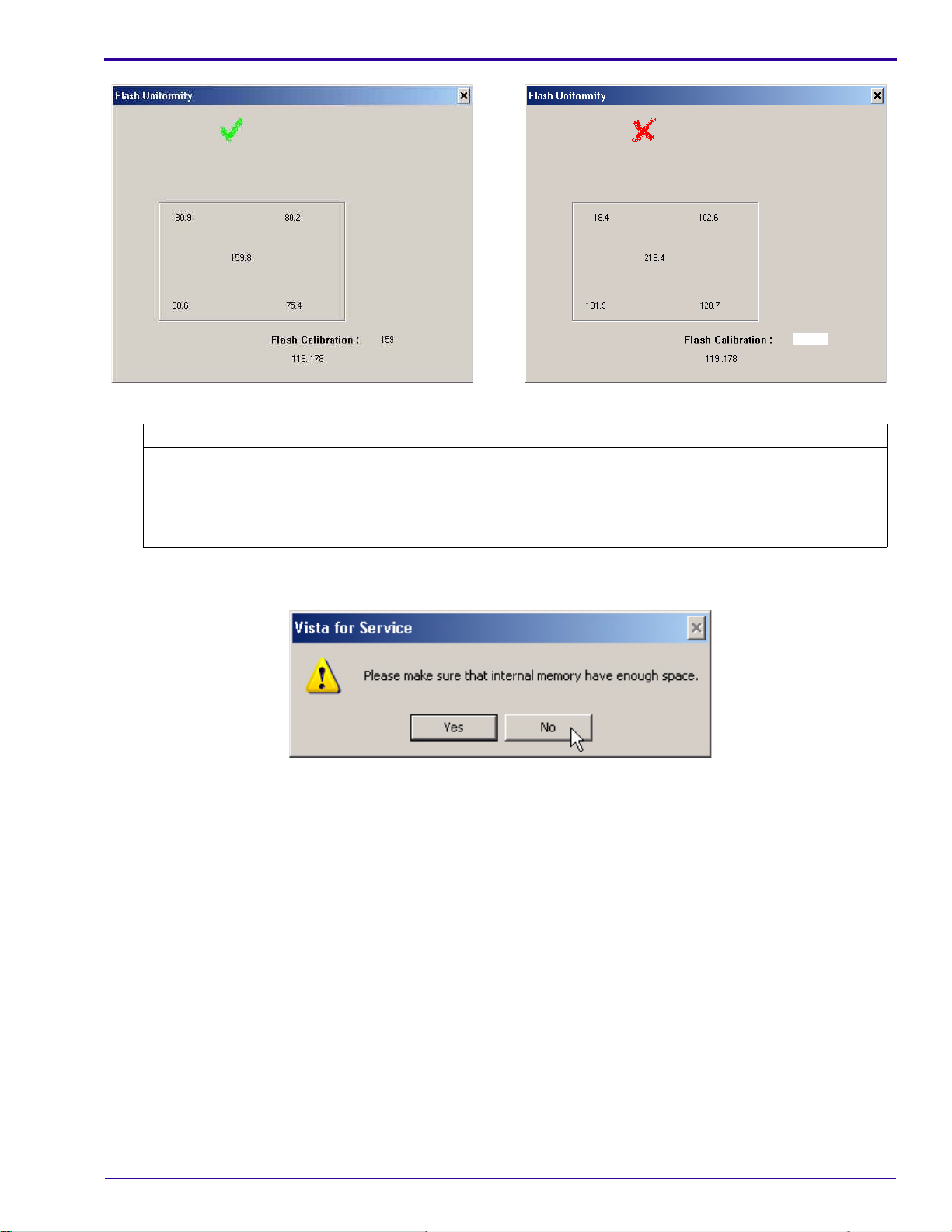
[10] Check the mark on the computer screen.
Green “✓” Red “X”
The test was successful.
Continue with Step 11
.
a. A failure occurred.
b. De-energize the CAMERA.
c. Do “
d. If the failure occurs again, check the setup of the hardware.
Diagnostics
Checking for Uniform Flash” on Page 23 again.
[11] Close the “Flash Uniformity” window.
[12] Click [No].
[13] Close the “VISTA for SERVICE (Kodak)” window.
SM8720-1 – 15APR10 25
Page 26

SERVICE MANUAL
Caution
Checkout Procedures
Checking the General Functions of the CAMERA
• Dangerous Voltage
• You must do these procedures before you return the CAMERA to the customer.
Checking the Power
[1] Install RECHARGEABLE BATTERIES that do not have a full charge into the CAMERA.
[2] Energize the CAMERA.
[3] Check that the CAMERA energizes.
[4] If the LCD displays the “Set Date & Time” options:
• select “Cancel”
• wait until the CAMERA completes energizing
[5] De-energize the CAMERA.
[6] Install a MEMORY CARD into the CAMERA.
[7] Energize the CAMERA.
[8] Check the energize sequence:
•LCD:
– displays the “Auto” mode for approximately 4 seconds
– does not display error codes
• LENS moves to the default “Wide” position
Checking the BUTTONS and SWITCHES
[1] Check the following BUTTONS and SWITCHES:
BUTTON/SWITCH Do:
•“Menu”
•4-WAY
•“OK”
• SHUTTER
1. Press the “Menu” BUTTON.
2. Check that the LCD displays options.
3. Press:
• 4-WAY BUTTON up or down to move through the menu
• “OK” BUTTON to select an option
• “OK” BUTTON again to return to the screen before
• “Menu” BUTTON to quit
• “Menu” BUTTON
• SHUTTER BUTTON
4. Check:
• CAMERA quits the menu
• image is captured
• image displays on the LCD
5. Capture one more image.
26 15APR10 – SM8720-1
Page 27

BUTTON/SWITCH Do:
• “Review”
• “share”
1. Press the “Review” BUTTON.
2. Check that the LCD illuminates.
3. Press:
• 4-WAY BUTTON left and right to display the images
• “share” BUTTON
4. If the “share” description displays, press “OK”.
5. Check that the “Favorites” icon displays in the lower left corner of the image.
6. Press:
• “share” BUTTON again to quit
• SHUTTER BUTTON
7. Check:
• CAMERA quits the “Review” mode
• image is captured
• image displays on the LCD
“Flash” 1. Check that the “Flash” icon displays in red in the top left corner.
2. Press the 4-WAY BUTTON up and down to check that the “Flash” icon
changes to:
• “Auto Flash”
• “Fill Flash”
•“Red Eye”
• “Flash Off”
3. Select “Flash On”.
4. Press the SHUTTER BUTTON.
5. Check:
• that the image is captured with the STROBE
• that the image displays on the LCD
6. Press the 4-WAY BUTTON up and down to check that the “Flash” icon
changes to “Flash Off”.
7. Press the SHUTTER BUTTON.
8. Check:
• that the image is captured without the STROBE
• that the image displays on the LCD
Diagnostics
SM8720-1 – 15APR10 27
Page 28

SERVICE MANUAL
BUTTON/SWITCH Do:
“Delete” 1. Press:
“Zoom” 1. Press the “Zoom” BUTTON toward “T”.
“Info” 1. Check that the LCD displays:
• “Review” BUTTON
• “Delete” BUTTON
2. Check that options display.
3. Select the “Exit” option.
4. Press:
• “OK” BUTTON to quit the “Delete” screen
• “Review” BUTTON to return to the “Auto” mode
• “Review” BUTTON again
• “Delete” BUTTON
• SHUTTER BUTTON to capture an image
5. Check:
• CAMERA quits the “Delete” screen
• image is captured
• image displays on the LCD
6. Press the “Delete” BUTTON.
7. Use the 4-WAY BUTTON to select “Yes”.
8. Press:
• “OK” BUTTON
• “Review” BUTTON
9. Use the 4-WAY BUTTON to check that the image is removed.
10. Press the “Review” BUTTON to quit.
2. Check that the LENS moves to the “Tele” position.
3. Press the SHUTTER BUTTON to the “S1” position.
4. Check that the image on the LCD has focus.
5. Press the SHUTTER BUTTON to capture an image.
6. Check that the image has focus.
7. Press the “Zoom” BUTTON toward “W”.
8. Check that the LENS moves to the “Wide” position.
9. Press the SHUTTER BUTTON to the “S1” position.
10. Check that the image on the LCD has focus.
11. Press the SHUTTER BUTTON to capture an image.
12. Check that the image has focus.
• icon for the capture mode
• icon for the flash mode
• number of additional images that can be captured
2. Press the “Info” BUTTON.
3. Check that additional icons display.
4. Press the “Info” BUTTON again to quit.
[2] Check the MODE BUTTON.
28 15APR10 – SM8720-1
Page 29

MODE Do:
Note
Note
“Video”
This procedure also
does a test of the
MICROPHONE.
Diagnostics
1. Press:
• MODE BUTTON
• 4-WAY BUTTON to the “Video” icon
•“OK” BUTTON
2. Press and release the SHUTTER BUTTON.
3. During the video recording, check:
• “Rec” on the LCD flashes
• recording time displays on the LCD
4. Speak some words to make an audio file.
5. Press and release the SHUTTER BUTTON.
6. Check that the LCD displays “Play Video”.
7. Press the “OK” BUTTON.
8. Check that the video file plays back.
9. Press the “OK” BUTTON.
10. Check that the video stops.
11. Press the “OK” BUTTON again to continue the play back.
12. When the play back is complete, check that the LCD returns to “Liveview” mode.
The audio section of this video file is checked in the procedure “Checking the
Communication and Audio Functions” on Page 30.
“SCN” 1. Press:
• MODE BUTTON
• 4-WAY BUTTON to the “SCN” icon
•“OK” BUTTON
2. Press the 4-WAY BUTTON left and right.
3. Check:
• selected icon changes to red
• icon also displays in the top right corner of the LCD
“Blur Reduction” 1. Press:
• 4-WAY BUTTON to “Blur Reduction”
•“OK” BUTTON
2. Capture an image at the same time of shaking the CAMERA.
3. Check that the image displayed on the LCD has focus.
SM8720-1 – 15APR10 29
Page 30

SERVICE MANUAL
Note
Checking the Firmware Version, ACTUATION, FLASH, and POWER-ON COUNTERS
[1] Make a folder with the name “HiddenMenu” on a blank MEMORY CARD.
[2] De-energize the CAMERA.
[3] Insert the MEMORY CARD into the CAMERA.
[4] Energize the CAMERA.
[5] Press:
•“Menu” BUTTON
• 4-WAY BUTTON to the right to place the cursor on “Setup”
• 4-WAY BUTTON up once to place the cursor on “About”
• “OK” BUTTON to select “About”
[6] Check the firmware version.
[7] At the same time, press:
• and hold the “Delete” BUTTON
• 4-WAY BUTTON to the right
[8] Release the BUTTONS.
[9] Check that the LCD displays “HIDDEN MENU”.
[10] Press:
• 4-WAY BUTTON to “TOTAL INFO”
• “OK” BUTTON
[11] Record the information for the COUNTERS in the FEEDBACK SOFTWARE.
Display Description
“ID” Serial Number
“Boot” Boot Code Version
“MCU” Microprocessor Code Version
“Total Shot” Actuations
“Total Strobe” Strobe Count
“Total Power On” Power-on Count
“BATPWR” Battery Power
[12] Press:
• 4-WAY BUTTON to the left 2 times
• “Menu” BUTTON to quit
Checking the Communication and Audio Functions
[1] Connect the CAMERA to the computer with the USB CABLE.
[2] Download the images and the video file with the USER SOFTWARE.
[3] Check the quality of the images.
[4] To check for the correct operation of the MICROPHONE during the video recording, play back the video file on
the computer and listen to the audio file.
If successful, the following are operating correctly:
• USB CONNECTOR on the MAIN BOARD
• MICROPHONE
[5] De-energize the CAMERA.
30 15APR10 – SM8720-1
Page 31

Checking the External Components of the CAMERA
[1] Check the COVERS of the CAMERA for scratches.
[2] If necessary, install new COVERS.
[3] Clean:
• COVERS
• SCREEN on the LCD
• FLASH COVER
[4] Check and clean the LENS.
Diagnostics
SM8720-1 – 15APR10 31
Page 32

SERVICE MANUAL
Adjustment Specification
Caution
Important
Section 4: Adjustments
LENS AY, MAIN BOARD, STROBE BOARD AY - “Shutter Delay”
• Dangerous Voltage
• This calibration procedure must be run first on every CAMERA, including the MASTER CAMERA.
Purpose: To set the parameters for the speed of the SHUTTER.
Do When: • After installing a new:
– LENS AY
–CCD
– MAIN BOARD
– STROBE BOARD AY
• Exposure of the images displayed on the LCD is too high or too low.
Specification: No failure messages or red screen display.
Special Tools: • Computer with a MEMORY CARD READER/WRITER
• BATTERIES with a full charge for the CAMERA
• LIGHT BOX
• MEMORY CARD
Prerequisites:
None
To Check:
You cannot check this adjustment.
To Adjust:
[1] Do Preparing the “C140 Shutter_Delay” MEMORY CARD on Page 61.
[2] Insert into the CAMERA:
• BATTERIES with a full charge
• “C140 Shutter_Delay” MEMORY CARD
The LENS must:
• be placed in the center of the light
• not touch the screen of the LIGHT BOX
[3] Place the CAMERA in front of the LIGHT BOX.
[4] Set the LIGHT BOX to LV15.0.
[5] Energize the CAMERA.
[6] If the LCD displays “Set Date & Time”, select “Cancel”.
[7] Check that “Script Loading...” displays on the LCD.
32 15APR10 – SM8720-1
Page 33

[8] When the test is completed, check that the LCD displays:
• “Small Aperture” and a number
• “Big Aperture” and a number
• “Shutter Calibration OK”
•“Save OK”
[9] Press the “OK” BUTTON.
[10] De-energize the CAMERA.
[11] Remove the MEMORY CARD from the CAMERA.
[12] Did the LCD display a red screen?
Yes No
a. Do Step 1
b. If the test has a failure again, do a replacement of the CAMERA.
- Step 12 again up to 3 times.
Postrequisites:
None
Adjustments
The procedure is complete.
SM8720-1 – 15APR10 33
Page 34

SERVICE MANUAL
Adjustment Specification
Caution
Important
MASTER CAMERA - “Calibration of the MASTER CAMERA”
• Dangerous Voltage
• This procedure is only run with a MASTER CAMERA to make the calibration files.
Purpose: To set the values for the LIGHT BOX using the MASTER CAMERA.
Do When: Before calibrations of this type of CAMERA.
Specification: No failure messages display.
Special Tools: • Computer with a MEMORY CARD READER/WRITER
• BATTERIES with a full charge
• LIGHT BOX
• MEMORY CARD
Prerequisites:
[1] Do LENS AY, MAIN BOARD, STROBE BOARD AY - “Shutter Delay” on Page 32 with the MASTER CAMERA.
To Check:
You cannot check this adjustment.
To Adjust:
[1] Do Preparing the “C140 Master Camera” MEMORY CARD on Page 61.
[2] Insert into the MASTER CAMERA:
• BATTERIES with a full charge
• “C140 Master Camera” MEMORY CARD with the “Batch_Lamp” files
The LENS must:
• be placed in the center of the light.
• not touch the screen of the LIGHT BOX.
[3] Place the CAMERA in front of the LIGHT BOX.
[4] Set the LIGHT BOX to:
•LV10.0
• color temperature 4800 K
[5] Energize the CAMERA to execute the test.
[6] If the LCD displays “Set Date & Time”, select “Cancel”.
[7] Select “Master Big Lamp”.
[8] Press the “OK” BUTTON.
[9] When the test is completed, check that the LCD displays:
•“Done”
• “ISO Calibration Success”
[10] De-energize the CAMERA.
34 15APR10 – SM8720-1
Page 35

Adjustments
Important
Note
• 2 additional files are written to the MEMORY CARD.
• If you have only one LIGHT BOX, you must do this section of the calibration with the same LIGHT BOX.
• If you have more than one LIGHT BOX, you must do this section of the calibration with the other LIGHT BOX.
[11] Do Step 5
[12] Select “Master Small Lamp”.
[13] Press the “OK” BUTTON.
[14] If necessary, use the “Zoom” BUTTON to set the “Small Lamp” number to 1.
[15] Press the “Delete” BUTTON to execute the test.
[16] When the test is completed, check that the LCD displays “ISO Calibration Success”.
[17] De-energize the CAMERA.
[18] Remove the MEMORY CARD.
• The additional file “Small_Lamp_WK8_1.fig” was written on the MEMORY CARD.
• If you have more than one LIGHT BOX, you must remove the file “Small_Lamp_WK8_1.fig” from the MEMORY
CARD and do the calibration with the other LIGHT BOX.
• The additional files made by this procedure are necessary before you do Preparing the “C140
ISO_DBP_Shading” MEMORY CARD on Page 62.
[19] If the LCD displays a failure message, do the correction:
“W/O Shutter K” The calibration of the SHUTTER
“Memory Fail” A failure occurred during a test
“ISO Cal Fail” A failure occurred during the
to Step 6 again to run the 2nd section of the calibration.
Failure Cause Correction
Do:
was not correct.
of the memory.
calibration.
1. “
Preparing the “C140 Shutter_Delay” MEMORY
CARD” on Page 61
2. Preparing the “C140 Master Camera” MEMORY
CARD on Page 61 again
1. Do Preparing the “
CARD on Page 61 again.
2. If the message occurs again, use a new MASTER
CAMERA.
1. Check:
• LIGHT BOX
• LV value
2. Do Preparing the “
CARD on Page 61 again.
3. If necessary, use a new MASTER CAMERA.
C140 Master Camera” MEMORY
C140 Master Camera” MEMORY
Postrequisites:
None
SM8720-1 – 15APR10 35
Page 36

SERVICE MANUAL
Adjustment Specification
Caution
Important
LENS AY, MAIN BOARD: CCD - “ISO_DBP_Shading”
Dangerous Voltage
Purpose: To set the values for ISO, Dark Bad Pixels and Automatic White Balance of the CAMERA.
Do When: After installing a new:
•CCD
• LENS AY
• MAIN BOARD
Specification: • The failure messages do not display.
• “ISO Calibration Success” displays.
• “DBP Calibration Success” displays.
Special Tools: • Computer with a MEMORY CARD READER/WRITER
• BATTERIES with a full charge
• LIGHT BOX
• MEMORY CARDS
Prerequisites:
[1] Do:
• LENS AY, MAIN BOARD, STROBE BOARD AY - “Shutter Delay”
• MASTER CAMERA - “Calibration of the MASTER CAMERA” on Page 34
on Page 32
To Check:
You cannot check this adjustment.
To Adjust:
[1] Do “Preparing the “C140 ISO_DBP_Shading” MEMORY CARD” on Page 62.
[2] Insert into the CAMERA:
• BATTERIES with a full charge
• “C140 ISO_DBP_Shading” MEMORY CARD with the files and folders on the “C140 master camera”
MEMORY CARD from the procedure “
Page 34
• The prepared MEMORY CARD must be used to do the calibrations of the repaired CAMERAS.
• The LENS must:
– be placed in the center of the light
– not touch the screen of the LIGHT BOX
[3] Set the LIGHT BOX to LV10.
[4] Place the CAMERA in front of the LIGHT BOX.
[5] Energize the CAMERA.
[6] If the LCD displays “Set Date & Time”, select “Cancel”.
MASTER CAMERA - “Calibration of the MASTER CAMERA”” on
36 15APR10 – SM8720-1
Page 37

[7] Check that “Script Loading...” displays on the LCD.
[8] When the test is completed, check that the LCD displays “ISO_DBP Calibration Success”.
[9] Press the “OK” BUTTON.
[10] De-energize the CAMERA.
[11] Remove the MEMORY CARD from the CAMERA.
[12] If the LCD displays the failure message “ISO Cal Fail”:
• open the file “ISO_Result_WK8.txt” to determine the type of failure
• do the necessary correction
Failure Cause Correction
“W/O Shutter K” The calibration of the SHUTTER was
not correct.
“Memory Fail” A failure occurred during a test of the
memory.
“ISO Cal Fail” A failure occurred during the
calibration.
Do:
1. LENS AY, MAIN BOARD, STROBE BOARD
AY - “Shutter Delay” on Page 32
2. LENS AY, MAIN BOARD: CCD -
“ISO_DBP_Shading” on Page 36 again
1. Do LENS AY, MAIN BOARD
“ISO_DBP_Shading” on Page 36 again.
2. If the message occurs again, install a new
MAIN BOARD.
1. Check:
• LIGHT BOX
• LV value
2. Do LENS AY, MAIN BOARD
“ISO_DBP_Shading” on Page 36 again.
3. Install a new LENS AY.
4. If necessary, install a new MAIN BOARD.
Adjustments
: CCD -
: CCD -
Postrequisites:
None
SM8720-1 – 15APR10 37
Page 38

SERVICE MANUAL
Adjustment Specification
Caution
LENS AY, MAIN BOARD: Auto Focus - “EFA”
Dangerous Voltage
Purpose: To set the values for Automatic Focus.
Do When: After installing a new:
•CCD
• LENS AY
• MAIN BOARD
Specification: The message “EFA OK” displays on the LCD.
Special Tools: • Computer with a MEMORY CARD READER/WRITER
• BATTERIES with a full charge
• INFINITY COLLIMATOR VC-1100
• MEMORY CARDS
Prerequisites:
None
To Check:
You cannot check this adjustment.
To Adjust:
[1] Do “Preparing the “C140 EFA” MEMORY CARD” on Page 62.
[2] Insert into the CAMERA:
• BATTERIES with a full charge
• “C140 EFA” MEMORY CARD
[3] Place the CAMERA in front of the INFINITY COLLIMATOR.
[4] Energize the CAMERA.
[5] If the LCD displays “Set Date & Time”, select “Cancel”.
[6] Check that “Script Loading...” displays on the LCD.
[7] When the test is completed, check that the LCD displays “EFA OK”.
[8] De-energize the CAMERA.
[9] Remove the MEMORY CARD from the CAMERA.
[10] Did the LCD display the failure message “NG” and a red screen?
Yes No
a. Do Step 2
b. If the LCD displayed the failure message “NG” again, install a new LENS AY.
c. Do Step 2
- Step 10 again.
- Step 10 again.
Continue with Step 11
.
[11] Capture some images at a variation of zoom positions of the LENS.
[12] Review the images on the LCD.
[13] Check that the images are not too dark or too light.
38 15APR10 – SM8720-1
Page 39

[14] Press the “T” BUTTON to increase the magnification of the images to the maximum.
[15] Check that the images on the LCD have focus.
Postrequisites:
None
Adjustments
SM8720-1 – 15APR10 39
Page 40

SERVICE MANUAL
Adjustment Specification
Caution
LENS AY, MAIN BOARD: CCD - “Run_In_WBP”
Dangerous Voltage
Purpose: To set the values for “White Bad Pixels”.
Do When: After installing a new:
•CCD
• LENS AY
• MAIN BOARD
Specification: • “WBP” < 20,000
• The message “Calibration Success” displays on the LCD.
Special Tools: • Computer with a MEMORY CARD READER/WRITER
• BATTERIES with a full charge
• black cloth or dark GEN 3 TEST FIXTURE
• MEMORY CARD
Prerequisites:
None
To Check:
You cannot check this adjustment.
To Adjust:
[1] Do “Preparing the “C140 Run_In_WBP” MEMORY CARD” on Page 63.
[2] Insert into the CAMERA:
• BATTERIES with a full charge
• “C140 Run_In_WBP” MEMORY CARD
[3] Place the CAMERA in the dark GEN 3 TEST FIXTURE or with the black cloth covering the LENS.
[4] Energize the CAMERA.
[5] If the LCD displays “Set Date & Time”, select “Cancel”.
[6] Check that “Script Loading...” displays on the LCD.
[7] When the test is completed, check that the LCD displays:
• green screen
• “Calibration Success”
• “Take Image OK”
[8] De-energize the CAMERA.
[9] Remove the MEMORY CARD from the CAMERA.
40 15APR10 – SM8720-1
Page 41

[10] Did the LCD display a red screen and the failure message “Calibration Fail”?
Note
Yes No
a. Do Step 1
b. If the LCD displayed the failure message again, do Step 2
again, to 3 times total.
c. If the LCD displayed the failure message again, for a total of 3 times, do
a replacement of the CAMERA.
The CAMERA complies with the specification if the test is successful a minimum of once for 3 times run.
- Step 10 again.
- Step 10
The procedure is complete.
Postrequisites:
None
Adjustments
SM8720-1 – 15APR10 41
Page 42

SERVICE MANUAL
Adjustment Specification
Caution
Note
MAIN BOARD: Memory - “Reset”
Dangerous Voltage
Purpose: To set the values to the defaults.
Do When: • After installing a new LCD.
• Doing a reset might initialize the correct operation of the CAMERA.
Specification: The settings are reset to the defaults.
Special Tools: • Computer with a MEMORY CARD READER/WRITER
• BATTERIES with a full charge
• MEMORY CARD
Prerequisites:
None
To Check:
You cannot check this adjustment.
To Adjust:
[1] Do “Preparing the “C140 Reset” MEMORY CARD” on Page 64.
[2] Insert into the CAMERA:
• BATTERIES with a full charge
• “C140 Reset” MEMORY CARD
[3] Energize the CAMERA.
[4] If the LCD displays “Set Date & Time”, select “Cancel”.
[5] Check that “Script Loading...” displays on the LCD.
When the images are loaded and test is completed, the CAMERA de-energizes automatically.
[6] Remove from the CAMERA:
• MEMORY CARD
• BATTERIES
[7] Install the BATTERIES into the CAMERA again.
[8] Energize the CAMERA.
42 15APR10 – SM8720-1
Page 43

[9] Does the LCD display the “Language” screen?
Yes No
a. Select the
language.
b. Set the date and
time.
a. De-energize the CAMERA.
b. Remove the BATTERIES.
c. Install the BATTERIES.
d. Energize the CAMERA.
e. If the LCD does not display the “Languages” screen, do Step 1
f. De-energize the CAMERA.
g. Energize the CAMERA.
h. If the LCD does not display the “Languages” screen again, do a replacement
of the CAMERA.
Postrequisites:
None
Adjustments
- Step 9 again.
SM8720-1 – 15APR10 43
Page 44

SERVICE MANUAL
Adjustment Specification
Caution
Important
MAIN BOARD, LCD - “Select LCD”
Dangerous Voltage
Purpose: To set the type of the LCD.
Do When: • After installing a new MAIN BOARD.
• Before installing a new LCD.
Specification: No failure messages or red screen display.
Special Tools: • Computer with a MEMORY CARD READER/WRITER
• BATTERIES for the CAMERA
• MEMORY CARD
Prerequisites:
None
To Check:
You cannot check this adjustment.
To Adjust:
[1] Do Preparing the “Select LCD” MEMORY CARD on Page 63.
[2] Insert into the CAMERA:
• BATTERIES with a full charge
• “C140 Select LCD” MEMORY CARD
[3] Energize the CAMERA.
[4] If the LCD displays “Set Date & Time”, select “Cancel”.
[5] Check that “Script Loading...” displays on the LCD.
The replacement LCD is the type AUO.
[6] When the test menu displays, select the correct
type of LCD.
[7] Press the “OK” BUTTON.
[8] De-energize the CAMERA.
[9] Remove the MEMORY CARD from the CAMERA.
[10] Energize the CAMERA to check that the LCD displays information correctly.
[11] De-energize the CAMERA.
Postrequisites:
None
44 15APR10 – SM8720-1
Page 45

MAIN BOARD: Memory - “Serial Number”
Adjustment Specification
Caution
Dangerous Voltage
Purpose: To set the serial number.
Do When: After installing a new MAIN BOARD.
Specification: The software displays “Successfully Writing ID”.
Special Tools: • Computer with a MEMORY CARD READER/WRITER
• BATTERIES with a full charge
Prerequisites:
None
To Ch eck :
[1] Do Step 2 - Step 7 of the procedure “To Adjust”.
[2] Click [Read].
[3] Check the “USB Serial Number” field for the serial
number.
[4] Click [OK].
Adjustments
SM8720-1 – 15APR10 45
Page 46

SERVICE MANUAL
To Adjust:
[1] Insert BATTERIES with a full charge into the
CAMERA:
[2] Connect the USB CABLE to the computer.
[3] Double-click the “Vista for Service” icon.
[4] At the same time, press and hold:
• “Tele” BUTTON
• “Review” BUTTON
• “On/Off” BUTTON
[5] Release the BUTTONS to energize the CAMERA.
[6] If the LCD displays “Set Date & Time”, select
“Cancel”.
[7] Connect the USB CABLE to the CAMERA.
[8] Click the “Write” icon.
[9] Click [Write] in the “USB Serial Number” section.
[10] Type the serial number in the “USB Serial
Number” field.
[11] Click [Write] again.
[12] Check that “Successfully Writing ID” displays.
[13] Click:
•[OK]
• [OK] to close the “Read/Write Barcode & USB
SN” window
[14] Close the “VISTA for SERVICE (Kodak)” window.
[15] De-energize the CAMERA.
[16] Disconnect the USB CABLE from the CAMERA.
[17] Do “
Checking the Firmware Version,
ACTUATION, FLASH, and POWER-ON
COUNTERS” on Page 30.
Postrequisites:
None
46 15APR10 – SM8720-1
Page 47

Section 5: Replacements
Caution
P291_1006AC
SOLDER JOINT
SOLDER JOINT
SCREW
P291_1006ACB
LCD
Prerequisites:
[1] Do the procedure “MAIN BOARD, LCD - “Select LCD”” on Page 44.
[2] See the “
• BACK COVER AY
• FRONT COVER AY
To Re mov e:
COVER AYs, BATTERY DOOR AYs and LCD” on Page 9. Remove:
Dangerous Voltage
[1] Do a discharge of the FLASH CAPACITOR.
[2] Remove:
• 3 SOLDER JOINTS
• SCREW
Replacements
P291_1007ACA
P291_1007AC
MONITOR LCD
HOLDER
FPC
MONITOR
LCD
CONNECTOR
[3] Remove the LCD HOLDER.
[4] Do a complete turnover of the LCD.
[5] Disconnect the FPC from the CONNECTOR.
[6] Remove the LCD.
SM8720-1 – 15APR10 47
Page 48

SERVICE MANUAL
Important
AUO
• The replacement LCD is the type AUO.
• The LCD that is removed from the CAMERA might not be the type AUO.
[7] See the graphic for an example of the type.
To Install:
[1] Reverse the steps in the removal procedure.
Postrequisites:
None
48 15APR10 – SM8720-1
Page 49

Additional Service Procedures
Section 6: Additional Service Procedures
Downloading the Files from the Partner Site
[1] From the Kodak Partner site, download the software and firmware files from Kodak EasyShare C140/CD93
DIGITAL CAMERA - Software and Firmware.
[2] Right-click the file “C140_Software_and_Firmware.zip”.
[3] Select WinZip>Extract to here.
[4] Open the folder “Service_Software”.
[5] Check for the folders:
•“Scripts”
• “upgrade KodakCam inf file”
• “Vista for Service V4.1.1.4”
[6] Open the folder “Scripts”.
[7] Check for the 9 folders.
• “Service_Software”
•“Scripts”
[8] Open the folder “Firmware”.
[9] Right-click the “KC140xxx.zip” file.
[10] Select WinZip>Extract to here.
[11] Check for the firmware file “KC140.fw”.
SM8720-1 – 15APR10 49
Page 50

SERVICE MANUAL
Important
Installing the Altek Vista SERVICE SOFTWARE on the Computer
• Microsoft Windows XP OPERATING SYSTEM is necessary for the correct operation of the SERVICE
SOFTWARE.
• If an older “Vista for Service” is installed on the computer, you must remove that software before you continue
with this procedure.
[1] From the folder “Vista for Service V4.1.1.4”, double-click “Setup.exe”.
[2] Click [Next].
50 15APR10 – SM8720-1
Page 51

[3] Click [Next].
Additional Service Procedures
[4] If the error “ReadOnly File Detected” occurs, click [Yes].
[5] Check that an icon for the “Vista for Service” appears on the computer screen.
SM8720-1 – 15APR10 51
Page 52

SERVICE MANUAL
[6] Open the folder “upgrade KodakCam inf file”.
[7] Double-click the file “AInf.exe”.
[8] Click [Browse...].
[9] Select the file “KodakCam.inf”.
[10] Click [Open].
52 15APR10 – SM8720-1
Page 53

[11] Click:
• [Copy source INF file to Windows INFs directory]
•[Exit]
[12] On the CAMERA, press at the same time the BUTTONS:
• “Review”
• “Zoom”
• “On/Off”
[13] Release the BUTTONS to energize the CAMERA.
[14] Connect the CAMERA to the computer with the USB CABLE.
Additional Service Procedures
[15] If the Kodak EasyShare SOFTWARE detects the CAMERA, click:
• [Cancel]
•[Yes]
[16] At the lower right edge of the computer screen, right-click on the “Kodak” icon.
[17] Select “Shut Down Kodak EasyShare software”.
SM8720-1 – 15APR10 53
Page 54

SERVICE MANUAL
[18] If the screen displays, click [Cancel].
[19] Select Start>Settings>Control Panel.
[20] Double-click the “System” icon.
54 15APR10 – SM8720-1
Page 55

Additional Service Procedures
[21] At the “System Properties” window, select the
“Hardware” tab.
[22] Click [Device Manager].
[23] Double-click the “Imaging devices” icon.
[24] Check that “C140 Digital Camera” displays.
[25] Close all windows.
[26] De-energize the CAMERA.
[27] Remove the USB CABLE from the CAMERA.
[28] When the computer displays the “Desktop”,
double-click the “Vista for Service” icon.
[29] Energize the CAMERA.
[30] Connect the USB CABLE to the CAMERA.
[31] Continue with “
Doing the Configuration of the
SERVICE SOFTWARE” on Page 56.
SM8720-1 – 15APR10 55
Page 56

SERVICE MANUAL
Important
Doing the Configuration of the SERVICE SOFTWARE
You must do this procedure before the SERVICE SOFTWARE can be used.
[1] Double-click the “Vista for Service” icon.
[2] Click [OK].
[3] Select Settings>Password...
[4] Click [OK].
[5] Select Settings>Configuration...
56 15APR10 – SM8720-1
Page 57

Additional Service Procedures
Important
If the information is not the same, you must enter the information to match the graphic above.
[6] Check that the information in the fields on this screen match the graphic above.
[7] Click [OK].
[8] Select Settings>Specifications...
SM8720-1 – 15APR10 57
Page 58

SERVICE MANUAL
[9] Check that the path for the file “kodak.spe” is C:\Program Files\Altek Corp\Vista for Service\Kodak.spe
[10] Click [OK].
[11] De-energize the CAMERA.
58 15APR10 – SM8720-1
Page 59

Checking the Connection to the SERVICE SOFTWARE
Note
[1] Connect the USB CABLE to the computer.
[2] Double-click the “Vista for Service” icon.
[3] At the same time, press and hold:
• “Tele” BUTTON
• “Review” BUTTON
• “On/Off” BUTTON
[4] Release the BUTTONS to energize the CAMERA.
[5] Connect the USB CABLE to the CAMERA.
[6] Click the “Write” icon.
[7] In the “USB Serial Number” section, click [Read].
[8] If no errors display, the software and the CAMERA
have USB communication.
The serial number of the CAMERA displays in the field.
[9] Click [OK].
Additional Service Procedures
[10] If any of the error windows appear when you run the SERVICE SOFTWARE:
• Click [OK].
SM8720-1 – 15APR10 59
Page 60

SERVICE MANUAL
•Check:
– CAMERA is energized with the correct combination of BUTTONS
– connections for the USB CABLE
– connections for the AC ADAPTER
•Do:
– Step 19
on Page 50
– “Checking the Connection to the SERVICE SOFTWARE” on Page 59 again
- Step 27 of the procedure “Installing the Altek Vista SERVICE SOFTWARE on the Computer”
60 15APR10 – SM8720-1
Page 61

Preparing the MEMORY CARDS for Service
Important
Note
Preparing the “C140 Shutter_Delay” MEMORY CARD
Every CAMERA, including the MASTER CAMERA,
must have this procedure run first before any other
calibration. See LENS AY, MAIN BOARD, STROBE
BOARD AY - “Shutter Delay” on Page 32.
[1] Open the folder “Shutter delay”.
[2] Check for the folder “Batch”.
[3] Make a copy of the folder “Batch” to a blank
MEMORY CARD.
[4] Label the MEMORY CARD
“C140 Shutter_Delay”.
Preparing the “C140 Master Camera” MEMORY CARD
Additional Service Procedures
[1] Open the folders:
• “Service_Software”
• “master camera”
[2] Open the folder “Batch_Lamp”.
[3] Make a copy of the folder “Batch” to a blank
MEMORY CARD.
[4] Label the MEMORY CARD
“C140 Master Camera”.
• Additional files are made on this MEMORY CARD
when the procedure is run.
• The additional files are used in the next procedure.
SM8720-1 – 15APR10 61
Page 62

SERVICE MANUAL
Important
Preparing the “C140 ISO_DBP_Shading” MEMORY CARD
Additional files from the “C140 Master Camera”
MEMORY CARD are necessary for this procedure.
[1] Insert the “C140 Master Camera” MEMORY
CARD into the CARD READER of the computer.
[2] Open the folder “master camera” on the computer.
[3] Make a copy of the 3 additional files and the
folders from the “C140 Master Camera” MEMORY
CARD, from the completed procedure “
CAMERA - “Calibration of the MASTER
CAMERA”” on Page 34:
• “Big_Lamp_WK8.fig”
• “ISO_Result_WK8.txt”
• “Small_Lamp_WK8_1.fig”
[4] Paste the files and folders into the folder
“master_camera” on the computer to keep.
[5] Open the folder “ISO_DBP_Shading” on the
computer.
[6] Paste the files and the folder into the folder
“ISO_DBP_Shading”.
[7] From the folder “ISO_DBP_Shading”, make a
copy of the files and the folders to a blank
MEMORY CARD.
[8] Label the MEMORY CARD
“C140 ISO_DBP_Shading”.
MASTER
Preparing the “C140 EFA” MEMORY CARD
[1] Open the folder “EFA”.
[2] Check for folder “Batch”.
[3] Make a copy of the folder “Batch” to a blank
MEMORY CARD.
[4] Label the MEMORY CARD “C140 EFA”.
62 15APR10 – SM8720-1
Page 63

Preparing the “C140 Run_In_WBP” MEMORY CARD
[1] Open the folder “Run_In_WBP”.
[2] Check for the folder “Batch”.
[3] Make a copy of the folder “Batch” to a blank
MEMORY CARD.
[4] Label the MEMORY CARD
“C140 Run_In_WBP”.
Preparing the “C140 Video&TVTest” MEMORY CARD
[1] Open the folder “Video&TVTest”.
[2] Check for the folder “Batch”.
[3] Make a copy of the folder “Batch” to a blank
MEMORY CARD.
[4] Label the MEMORY CARD
“C140 Video&TVTest”.
Additional Service Procedures
Preparing the “Select LCD” MEMORY CARD
[1] Open the folder “Select LCD”.
[2] Check for the folder “Batch”.
[3] Make a copy of the folder “Batch” to a blank
MEMORY CARD.
[4] Label the MEMORY CARD
“C140 Select LCD”.
SM8720-1 – 15APR10 63
Page 64

SERVICE MANUAL
Preparing the “C140 Self_Test” MEMORY CARD
Preparing the “C140 Reset” MEMORY CARD
[1] Open the folder “selftest&keytest”.
[2] Check for the folder “Batch”.
[3] Make a copy of the folder “Batch” to a blank
MEMORY CARD.
[4] Label the MEMORY CARD
“C140 Self_Test”.
[1] Open the folder “Reset”.
[2] Check for the folder “Batch”.
[3] Make a copy of the folder “Batch” to a blank
MEMORY CARD.
[4] Label the MEMORY CARD
“C140 Reset”.
64 15APR10 – SM8720-1
Page 65

Using the “HIDDEN MENU” of the CAMERA
Caution
Displaying the “HIDDEN MENU”
Dangerous Voltage
[1] De-energize the CAMERA.
[2] Insert the MEMORY CARD into a CARD READER/WRITER.
[3] Make a folder with the name “HiddenMenu” on a blank MEMORY CARD.
[4] Remove the MEMORY CARD from the CARD READER.
[5] Insert into the CAMERA:
• MEMORY CARD
• BATTERIES that have a full charge
[6] Energize the CAMERA.
[7] If “Set Date & Time” displays, select “Cancel”.
[8] Press:
• “menu” BUTTON
• 4-WAY BUTTON to the right to select “Setup”
• 4-WAY BUTTON up one time to select “About”
•“OK” BUTTON
[9] Check that the firmware version displays.
[10] Press:
• press and hold the “delete” BUTTON
• 4-WAY BUTTON to the right
[11] Release the BUTTONS.
[12] Check that the LCD displays “HIDDEN MENU” and options.
[13] To quit, press the 4-WAY BUTTON left 2 times.
[14] De-energize the CAMERA.
[15] Remove the MEMORY CARD from the CAMERA.
Additional Service Procedures
Checking for the Firmware Version and the Type of LCD
[1] Do Step 1 - Step 12 of Displaying the “HIDDEN MENU”.
[2] Select “FIRMWARE VERSION” from the “HIDDEN MENU”.
[3] Press the “OK” BUTTON.
[4] Record the type of LCD.
[5] To q ui t, d o Step 13
SM8720-1 – 15APR10 65
- Step 15 of Displaying the “HIDDEN MENU”.
Page 66

SERVICE MANUAL
Caution
Upgrading the Firmware Using the MEMORY CARD
[1] Does the “Support Center” of the Kodak.com Web Site have the firmware file for this CAMERA?
Yes No
a. Download the “KC140xxx.exe” firmware file.
b. When downloading is complete, double-click the
“KC140xxx.exe” firmware file to decompress it to
the “KC140.fw” file.
c. Continue with Step 2
[2] Energize the CAMERA.
[3] Press the “Menu” BUTTON.
[4] Check that “Auto” is selected for the “Image Storage”.
[5] Press the “Menu” BUTTON to quit.
[6] De-energize the CAMERA.
[7] Insert the MEMORY CARD into a CARD READER/WRITER.
[8] Delete all of the files and folders on the MEMORY CARD.
[9] Make:
• folder in the root directory on the MEMORY CARD with the name “system”
• copy of the “KC140.fw” firmware file to the “system” folder on the MEMORY CARD
[10] Remove the MEMORY CARD from the CARD READER.
.
a. The file you downloaded from the Kodak Partner
Site is the highest version. Do the procedure
using that file.
b. Continue with Step 2
.
Dangerous Voltage
[11] Insert into the CAMERA:
• BATTERIES that has a full charge
• MEMORY CARD with the firmware file
[12] Energize the CAMERA.
[13] Select:
• “Upgrade”
•“OK”
[14] Check that downloading:
• begins
• completes
[15] Select “Exit”.
[16] De-energize the CAMERA.
[17] Remove the MEMORY CARD from the CAMERA.
[18] Energize the CAMERA.
[19] Press the “Menu” BUTTON.
[20] Select:
• “Setup”
• “About”
[21] Check:
• firmware on the CAMERA is the correct version
• CAMERA operates correctly
[22] De-energize the CAMERA.
66 15APR10 – SM8720-1
Page 67

Section 7: Diagrams
System Connections
Diagrams
SM8720-1 – 15APR10 67
Page 68

SERVICE MANUAL
MAIN BOARD, 1 of 8
P323_0005FC_
Schematics
MAIN BOARD, 1 of 8
68 15APR10 – SM8720-1
Page 69

MAIN BOARD, 2 of 8
MAIN BOARD, 2 of 8
P323_0006FC_
Diagrams
SM8720-1 – 15APR10 69
Page 70

SERVICE MANUAL
P323_0007FC_
MAIN BOARD, 3 of 8
MAIN BOARD, 3 of 8
70 15APR10 – SM8720-1
Page 71

MAIN BOARD, 4 of 8
P323_0008FC_
MAIN BOARD, 4 of 8
Diagrams
SM8720-1 – 15APR10 71
Page 72

SERVICE MANUAL
MAIN BOARD, 5 of 8
P323_0009FC_
MAIN BOARD, 5 of 8
72 15APR10 – SM8720-1
Page 73

MAIN BOARD, 6 of 8
P323_0010FC_
MAIN BOARD, 6 of 8
Diagrams
SM8720-1 – 15APR10 73
Page 74

SERVICE MANUAL
P323_0011FC_
MAIN BOARD, 7 of 8
MAIN BOARD, 7 of 8
74 15APR10 – SM8720-1
Page 75

MAIN BOARD, 8 of 8
P323_0012FC_
MAIN BOARD, 8 of 8
Diagrams
SM8720-1 – 15APR10 75
Page 76

SERVICE MANUAL
P323_0013BC_
STROBE BOARD, 1 of 3
P323_0014BC_
STROBE BOARD, 2 of 3
STROBE BOARD, 1 of 3
STROBE BOARD, 2 of 3
76 15APR10 – SM8720-1
Page 77

STROBE BOARD, 3 of 3
P323_0015HC_
STROBE BOARD, 3 of 3
Diagrams
SM8720-1 – 15APR10 77
Page 78

SERVICE MANUAL
P323_0002HC_
F600
MAIN BOARD, Top
Component Layout
MAIN BOARD, Top
78 15APR10 – SM8720-1
Page 79

MAIN BOARD, Bottom
MAIN BOARD, Bottom
P323_0001HC_
Diagrams
SM8720-1 – 15APR10 79
Page 80

SERVICE MANUAL
P323_0003HC_
STROBE BOARD, Top
F800
STROBE BOARD, Bottom
P323_0004HC_
STROBE BOARD, Top
STROBE BOARD, Bottom
80 15APR10 – SM8720-1
Page 81

Section 8: Publication History
Publication History
Publication
Date
22APR09 SM8720-1 --- sm8720_1.fm New Publication
28APR09 SM8720-1 5, 6, 8, 9, 14,
21JUL09 SM8720-1 6, 9, 14 sm8720_1.fm Added catalog and part numbers for the new color
09SEP09 SM8720-1 12 - 14 sm8720_1.fm Added part numbers for:
18NOV09 SM8720-1 6, 10, 14 sm8720_1.fm Added the information for the CD14 DIGITAL
07JAN10 SM8720-1 6, 10, 15 sm8720_1.fm Added the information for the silver with black CD14
15APR10 SM8720-1 11, 15 sm8720_1.fm Added the part number for the MAIN BOARD AY for
Publication
No.
Changed
Pages
29, 65
File
Name Notes
sm8720_1.fm • Changed:
– BATTERY from KAA2HR to BATTERIES, AA
– color of silver COVERS to silver-beige
– sequence of parts in the COVER AYs,
BATTERY DOOR AYs and LCD table
• Removed procedure about boot code.
orange.
• CCD
• UV-IR CUT FILTER
CAMERA.
DIGITAL CAMERA.
GAR.
SM8720-1 – 15APR10 81
Page 82

Kodak and EasyShare are trademarks of Eastman Kodak Company.
Printed in U.S.A. • sm8720_1.fm
EASTMAN KODAK COMPANY
Rochester, NY 14650
 Loading...