

Knight Equipment PB1-4-A Service Manual
SERVICE & OPERATING MANUAL
II 2GD T5
Model PB¼-A
Type 3
Air-Operated
Double Diaphragm Pump
Table of Contents
Engineering Data and Temperature Limitations .....................1
Performance Curve................................................................1
CE
U.S. Patent #
5,996,627 and
6,241,487
Explanation of Pump Nomenclature ......................................2
Dimensions ............................................................................3
Metric Dimensions .................................................................4
Principle of Pump Operation ..................................................5
Check Valve Servicing ...........................................................5
Diaphragm Servicing .............................................................5
Troubleshooting .....................................................................6
Warranty ................................................................................6
Recycling ...............................................................................6
Important Safety Information .................................................6
Material Codes ......................................................................7
Installation Guide ...................................................................7
Composite Repair Parts Drawing ..........................................8
Available Service and Conversion Kits ..................................8
Composite Repair Parts List ..................................................9
Grounding the Pump .............................................................9
Solenoid Shifted Option Drawing .........................................10
Solenoid Shifted Air Valve Parts List ...................................10
Solenoid Shifted Options .....................................................11
Solenoid Connector Drawing ...............................................11
CE Declaration of Conformity ..............................................12
WARREN RUPP, INC. • A Unit of IDEX Corporation • P.O. Box 1568, Mansfi eld, Ohio 44901-1568 USA • Telephone (419) 524-8388 • Fax (419) 522-7867
www.warrenrupp.com pb025nmdl3sm-REV1008

Quality System
II 2GD T5
II 2GD T5
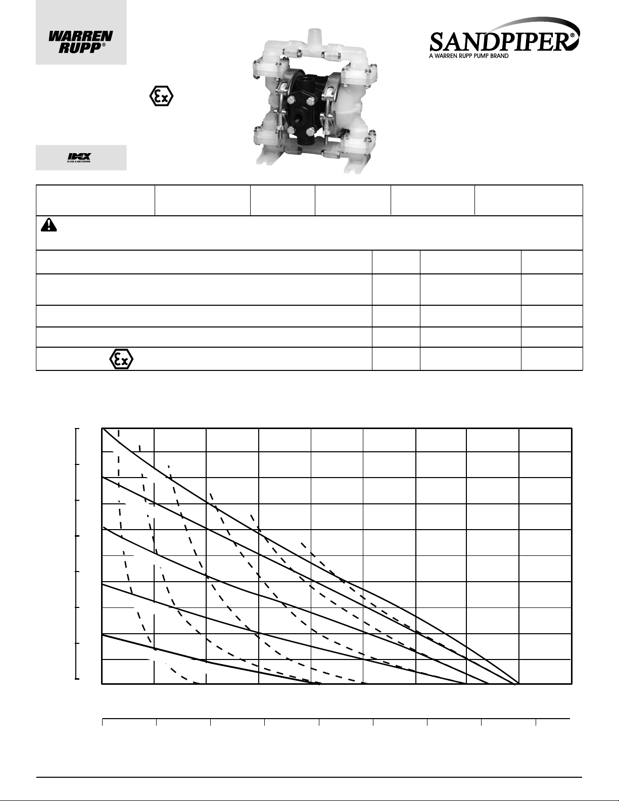
Liters per minute
100
90
80
70
60
50
40
30
20
10
0 .5 1.0
2.5 3.0 3.5 4.0 4.51.5
2.0
U.S. Gallons per minute
BAR
PSI
HEAD
1
2
3
4
5
6
7
0
0246810121416
100 PSI (6.8 Bar)
80 PSI (5.44 Bar)
60 PSI (4.08 Bar)
40 PSI (2.72 Bar)
20 PSI (1.36 Bar) Air Inlet Pressure
0
AIR CONSUMPTION SCFM (M3/hr)
1(1.7)
2(3.4)
3(5.1)
4(6.8)
5(8.5)
6(10.2)
MODEL PB¼-A Performance Curve
Performance based on the following: elastomer fitted pump, flooded suction, water at ambient conditions.
The use of other materials and varying hydraulic conditions may result in deviations in excess of 5%.
ISO9001 Certifi ed
Environmental
Management System
ISO14001 Certifi ed
CE
U.S. Patent #
5,996,627 and
6,241,487
Model PB¼-A
Type 3
Air-Operated
Double Diaphragm Pump
Engineering, Performance
& Construction Data
INTAKE/DISCHARGE PIPE SIZE
¼" (6mm) NPT (internal)
½" (13mm) NPT (external)
CAPACITY
0 to 4 gallons per minute
(0 to 15 liters per minute)
AIR VALVE
No-lube, no-stall
design
CAUTION! Operating temperature limitations are as follows:
Materials
Santoprene® Injection molded thermoplastic elastomer with no fabric layer. Long mechanical flex life.
Excellent abrasion resistance.
Virgin PTFE Chemically inert, virtually imper vious. Very few chemicals are known to react chemically
with PTFE: molten alkali metals, turbulent liquid or gaseous fluorine and a few fluoro-chemicals such
as chlorine trifluoride or oxygen difluoride which readily liberate free fluorine at elevated temperatures.
PVDF
Polypropylene
Conductive Acetal
SOLIDS-HANDLING
Up to 1/32" (1mm)
HEADS UP TO
100 psi or 231 ft. of water
(7 bar or 70 meters)
Maximum*
°F
275
135°C
220°F
104°C
250°F
121°C
180°F
82°C
190°F
88°C
DISPLACEMENT/STROKE
.01 US Gallons / .04 liters
Operating Temperatures
Minimum*
-40°F
-40°C
-35°F
-37°C
0°F
-18°C
32°F
0°C
-20°F
-29°C
Optimum**
50° to 212°F
10° to 100°C
50° to 212°F
10° to 100°C
(SANDPIPER
pb025nmdl3sm-REV1008 Page 1
®
pumps are designed to be powered only by compressed air)
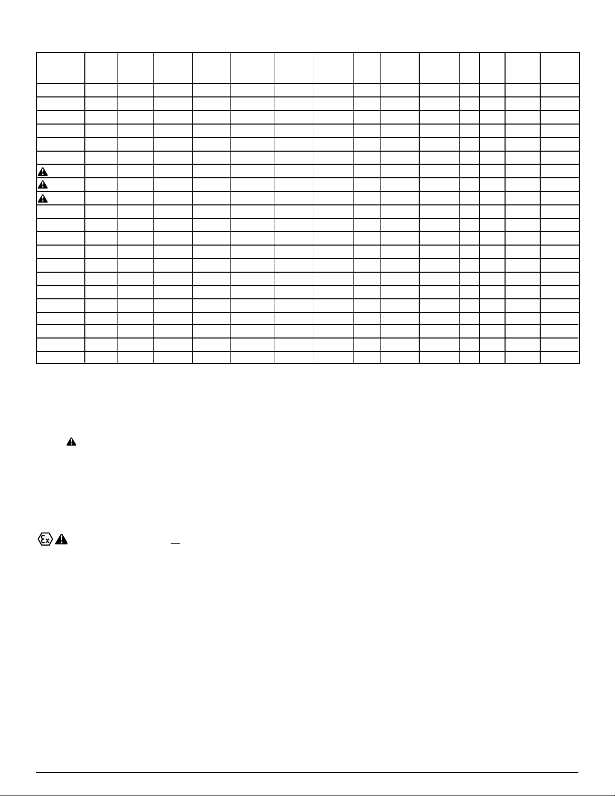
Explanation of Pump Nomenclature
PB¼-A
Manifold
Outer
Chamber
Outer
Diaphragm
Plate
Inner
Diaphragm
Plate
Intermediate
Housing
Diaphragm
Rod
Hardware
Valve
Seat
Diaphragm
Ball Valve
Material
Air
Valve
Cap
Options
Shipping
Weight
(lbs.)
PP
TU-3-PP PP 2011-AL PP* 416SS 301/302SS PP S T 4
TT-3-PP PP 2011-AL PP* 416SS 301/302SS PP T T 4
TS-3-K K
TU-3-K K
TT-3-K K
TS-3-CA CA
TU-3-CA CA
TT-3-CA CA
TS-3-PPE0
TS-3-PPE1
TS-3-PPE2
TS-3-PPE3
TS-3-PPE4
TS-3-PPE5
TS-3-PPE6
TS-3-PPE7
TS-3-PPE8
TS-3-PPE9
TS-3-PPP0
TS-3-PPP2
Horizontal suction and vertical discharge are standard. All combinations of suction and discharge are available.
PP
PP
K
K
K
CA
CA
CA
PP
PP
PP
PP
PP
PP
PP
PP
PP
PP
PP
PP
PP PP 2011-AL PP* 416SS 301/302SS PP S S
PP
PP
2011-AL PP* 416SS 301/302SS K S S 5
2011-AL PP* 416SS 301/302SS K S T 5
2011-AL PP* 416SS 301/302SS K T T 5
2011-AL CA* 301/302SS AC S S 4
2011-AL CA* 416SS 301/302SS AC S T 4
2011-AL CA* 416SS 301/302SS AC T T 4
2011-AL
2011-AL
2011-AL
2011-AL
2011-AL
2011-AL
2011-AL
2011-AL
2011-AL
2011-AL
2011-AL
2011-AL
PP*
PP*
PP*
PP*
PP*
PP*
PP*
PP*
PP*
PP*
PP*
PP*
416SS
416SS
416SS
416SS
416SS
416SS
416SS
416SS
416SS
416SS
416SS
416SS
416SS
301/302SS
301/302SS
301/302SS
301/302SS
301/302SS
301/302SS
301/302SS
301/302SS
301/302SS
301/302SS
301/302SS
301/302SS
PP
PP
PP
PP
PP
PP
PP
PP
PP
PP
PP
PP
S
S
S
S
S
S
S
S
S
S
S
S
PP
PP
PP
PP
PP
PP
PP
PP
PP
PP
PP
PP
K
K
K
CA
CA
CA
PP
PP
PP
PP
PP
PP
PP
PP
PP
PP
PP
PP
S
S
S
S
S
S
S
S
S
S
S
S
PP*
PP*
PP*
PP*
PP*
PP*
PP*
PP*
PP*
PP*
PP*
PP*
CA*
CA*
CA*
CA*
CA*
CA*
PP*
EE0
PP*
EE1
PP*
EE2
PP*
EE3
PP*
E
PP*
E
PP*
E
PP*
E
E
PP*
E
PP*
PP
PP*
PP*
PP
-
-
-
-
-
-
-
-
-
E4
E5
E6
E7
E8
E9
P0
P2
4TS-3-PP
4
4
4
4
4
4
4
4
4
4
4
4
Meanings of Abbreviations:
AC = Acetal
AL = Aluminum
CA = Conductive Acetal**
K = PVDF
PP = Polypropylene
SS = Stainless Steel
T = PTFE
S = Santoprene
ATEX Compliant ONLY with no options.
* Designates Glass Filled
** Note: Only Conductive Acetal equipped pumps with no options are ATEX compliant
Kit Options
00.= None
P0.= 10-30VDC Pulse Output Kit
P2.= 110/120 or 220/240VAC
Pulse Output Kit
E0.= Solenoid Kit w/24VDC Coil
E1.= Solenoid Kit w/24VDC
Explosion-Proof Coil
E2.= Solenoid Kit w/24VAC/12VDC Coil
E3.= Solenoid Kit w/12VDC Coil
Explosion-Proof
E4.= Solenoid Kit w/110VAC Coil
E5.= Solenoid Kit w/110VAC
Explosion-Proof Coil
E6.= Solenoid Kit w/220VAC Coil
E7.= Solenoid Kit w/220VAC
Explosion-Proof Coil
E8.= Solenoid Kit with 110VAC, 50 Hz
Explosion-Proof Coil
E9.= Solenoid Kit with 230VAC, 50 Hz
Explosion-Proof Coil
SP.= Stroke Indicator Pins
pb025nmdl3sm-REV1008 Page 2

Dimensions: PB¼-A Non-Metallic
Dimension
Standard
Pulse Output Kit
pb025nmdl3sm-REV1008 Page 3
A B
7" 3 1/8"
7" 3 1/8" 5 1/2"
C
5 1/2"
 Loading...