

KitchenAid KKFV01LP Series, KKFV01PP Series Installation Instructions And Use And Care Manual
KITCHEN FAUCETS
Installation Instructions and Use & Care Guide
For questions about features, operation/performance, parts, accessories, or service, call: 1-800-422-1230 or visit our website at...
www.kitchenaid.com
Model Series
KKFV01SP
Model Series
KKFV01PP
READ AND SAVE THESE INSTRUCTIONS
FOR RESIDENTIAL USE ONLY
IMPORTANT:
Installer: Leave installation instructions with the homeowner.
Homeowner: Keep installation instructions for future reference.
Model Series
KKFV01LP
8559765B
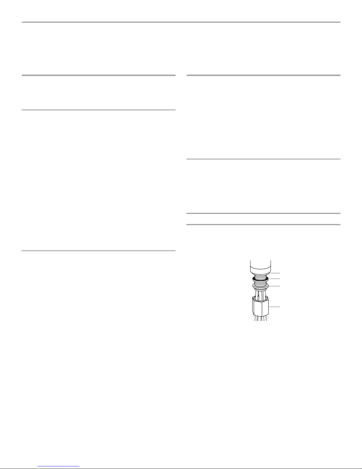
TABLE OF CONTENTS
INSTALLATION REQUIREMENTS ................................................2
INSTALLATION INSTRUCTIONS ..................................................2
FAUCET USE ..................................................................................4
FAUCET CARE................................................................................ 4
TROUBLESHOOTING ....................................................................5
REPLACEMENT PARTS LISTS .....................................................6
WARRANTY ....................................................................................8
INSTALLATION
REQUIREMENTS
Tools and Parts
Gather the required tools before starting installation. Remove
parts from carton. Check that all parts are included.
Tools Needed:
■ Adjustable wrench
■ Basin wrench (optional)
Parts Supplied:
All models:
■ Faucet assembly
■ ⁵⁄₆₄" Allen wrench
Model series KKFV01SP and KKFV01PP:
■ Weights (2) ■ Check valve assembly
Location Requirements
IMPORTANT:
■ Observe all governing codes and ordinances.
■ Check location where faucet will be installed. Proper
installation is your responsibility. Make sure you have
everything necessary for installation. It is the responsibility of
the installer to comply with installation specifications and with
state and local plumbing codes.
■ Keep faucet and water lines leading to faucet from freezing to
avoid damage.
■ The faucet requires a 1³⁄₈" (3.5 cm) diameter opening in sink
or countertop. If there is no hole for mounting, it is
recommended that you contact a qualified installer to drill the
hole for your installation in a sink deck or countertop.
NOTE: The thickness of the sink or countertop must not
exceed 1³⁄₄" (4.4 cm).
■ Hot and cold water supply lines must be available. If the
water lines are not available, it is recommended that you
contact a qualified plumber to install the necessary piping.
■ Faucet hoses are equipped with compression type seals and
do not require sealing compound to keep from leaking.
■ As with all metal objects, follow proper handling techniques.
■ #2 Phillips screwdriver
■ Slip joint pliers
■ Mounting assembly
-Rubber O-ring
-Flat rubber washer
-White triangular support
-Flat metal washer
-Threaded collar
-fiber seals (2)
INSTALLATION
INSTRUCTIONS
IMPORTANT:
■ It is recommended that a qualified plumber/installer install the
faucet. The faucet installation must comply with national and
local plumbing codes and ordinances.
■ The faucet should be examined for damage prior to
installation. Do not install a damaged faucet. Instead, return
the faucet to the dealer from whom you purchased it.
Install the Faucet
IMPORTANT:
■ Before installing the faucet, flush water supply pipes
thoroughly. Shut off water supply valves.
■ Follow the installation instructions specific to your faucet
model.
Models KKFV01SP and KKFV01PP
1. Remove the threaded collar, flat metal washer, and flat rubber
washer from faucet.
NOTE: Do not remove the rubber O-ring from the bottom of
the faucet base.
A
B
C
D
A. Rubber O-ring
B. Flat rubber washer
2. Insert faucet into sink or countertop.
■ Feed tubing through the hole in the sink or countertop.
■ Insert threaded shank into the hole.
NOTE: Make sure the rubber O-ring in the channel at the
bottom of the faucet base is firmly in place.
C. Flat metal washer
D. Threaded collar
2
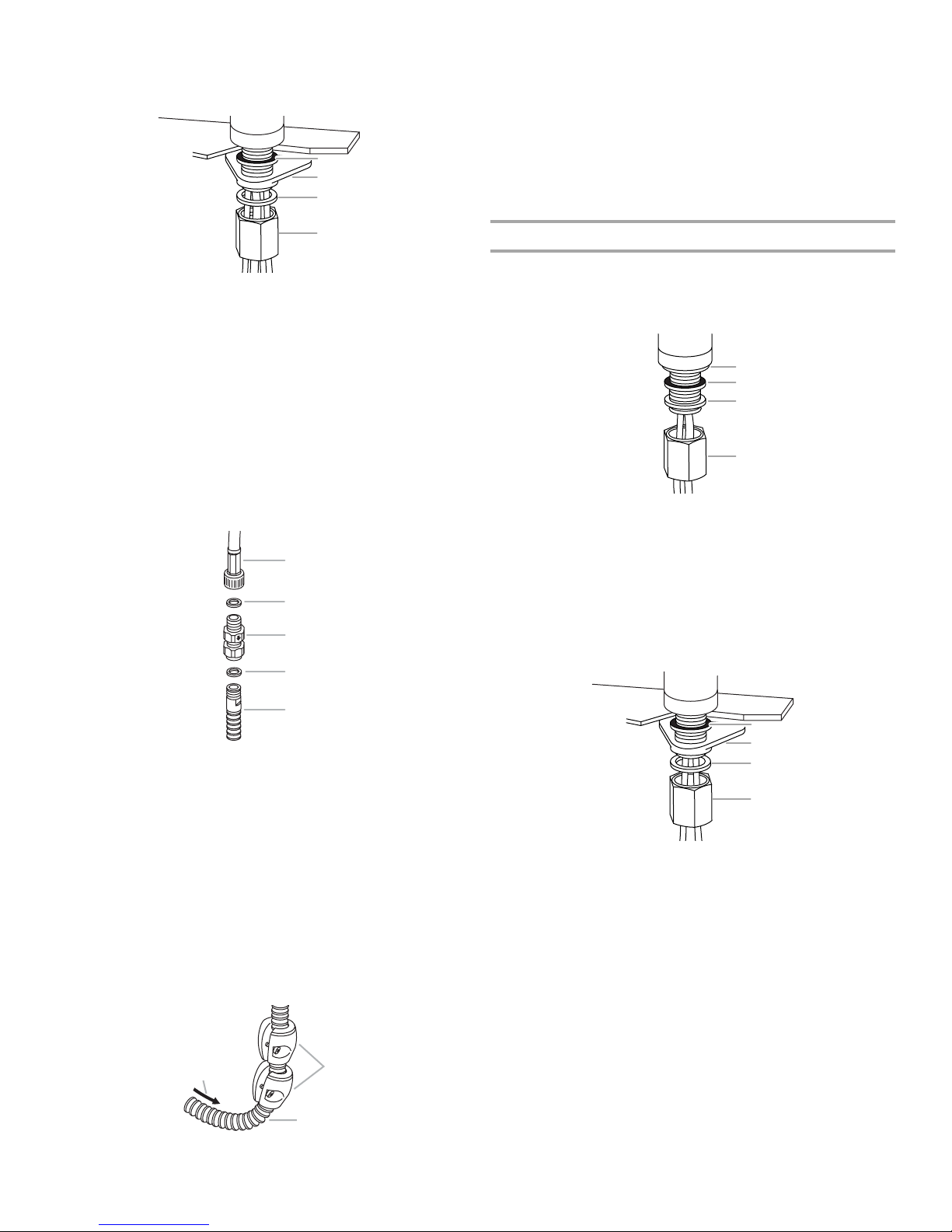
3. Working from under the sink or countertop, reinstall the parts
A
B
C
D
E
A
onto the threaded shank of the faucet in the following order:
flat rubber washer, white triangular support, flat metal washer,
and threaded collar.
A
B
C
10. Move the faucet lever to the closed (forward) position and
open supply valves. Check connections for leaks.
11. Remove the aerator from the faucet and flush the hot and
cold lines until water is clear.
NOTE: The aerator is in the end of the faucet. To remove and
replace aerator, see “Aerator Assembly” in the “Faucet Care”
section.
12. Reinstall the aerator into the faucet and tighten with a
wrench.
D
A. Flat rubber washer
B. White triangular support
C. Flat metal washer
D. Threaded collar
4. Align the faucet and firmly hand-tighten the threaded collar to
keep the faucet base from turning when moving the control
lever. Make sure the control lever is pointed toward the righthand side of the sink.
5. Connect the sprayer hose to the water supply hose using the
check valve assembly and the fiber washers. Make sure the
check valve assembly is positioned so that the arrow is
pointing down, away from the faucet and toward the sprayer
head.
6. Place a fiber washer between the sprayer hose and the check
valve assembly and fasten them together. Then, place a fiber
washer between the check valve assembly and the supply
hose and fasten them together, as shown.
Model KKFV01LP
1. Remove the threaded collar, flat metal washer, and flat rubber
washer from faucet.
NOTE: Do not remove the rubber O-ring from the bottom of
the faucet base.
A
B
C
D
A. Rubber O-ring
B. Flat rubber washer
2. Feed tubing through the hole in the sink or counter top and
then insert threaded shank into the hole. Make sure the
rubber O-ring in the channel at the bottom of the faucet base
is firmly in place.
3. Working from under the sink or countertop, reinstall the parts
onto the threaded shank of the faucet in the following order:
flat rubber washer, white triangular support, flat metal washer,
and threaded collar.
C. Flat metal washer
D. Threaded collar
A. Supply hose (from faucet)
B. Fiber washer
C. Check valve assembly
D. Fiber washer
E. Sprayer hose
7. Connect the red-striped, braided hose to the hot water
supply valve. Connect the blue-striped, braided hose to the
cold water supply valve. Hold the hoses in place when
tightening the nut to keep the hoses from twisting.
8. Make sure the sprayer hose is fully inserted into the faucet
body.
9. Working from under the sink, use the screws provided to
attach the weights onto the sprayer hose. Attach the weights
to the sprayer head side of the hose loop, just above the
bend in the hose, as shown.
NOTE: The weights are for counterbalance only, not for
automatic retraction.
C
A. Weights
B. Sprayer hose
B
C. Water flow direction
A
B
C
D
A. Flat rubber washer
B. White triangular support
C. Flat metal washer
D. Threaded collar
4. Align the faucet and firmly hand-tighten the threaded collar to
keep the faucet base from turning when moving the operating
lever.
5. Connect the red-striped, braided hose to the hot water
supply valve. Connect the blue-striped, braided hose to the
cold water supply valve. Hold the hoses in place when
tightening the nut to keep the hoses from twisting.
6. Move the faucet lever to the closed (forward) position and
open supply valves. Check connections for leaks.
7. Remove the aerator from the faucet and flush the hot and
cold lines until water is clear.
NOTE: The aerator is in the end of the faucet. To remove and
replace aerator, see “Aerator Assembly” in the “Faucet Care”
section.
8. Reinstall the aerator into the faucet and tighten with a
wrench.
3
 Loading...