

Page 1

Owner’s Manual
Manual del Propietario
Manuel d’utilisatio
Benutzerhandbuch
LX Amplifiers
select language
seleccione
el idioma
choisir la
langue
sprache
auswählen
Page 2

Contents
Overview ........................4
Warranty ......................82
Garantía | Garantie ......323
LX Mono
Specifications ........................ 5
Installation ......................7
Mounting ............................... 7
Power Wiring ....................... 10
Input Wiring ......................... 13
Subwoofer Wiring ................ 14
Operation .....................15
LXRC Installation .................. 22
LXRC Operation .................. 26
Troubleshooting ............29
LX Stereo
Specifications ...................... 30
Installation ....................31
Mounting ............................. 31
51LX-h-250324
2English
Page 3

Power Wiring ....................... 34
Input Wiring ......................... 37
Speaker Wiring .................... 38
Operation .....................41
LXCC .................................. 47
Troubleshooting ............50
LX Multi-Channel
Specifications ...................... 51
Installation ....................52
Mounting ............................. 52
Power Wiring ....................... 55
Input Wiring ......................... 58
Speaker Wiring .................... 60
Operation .....................64
LXCC .................................. 70
LXRC Installation .................. 74
LXRC Operation .................. 78
Troubleshooting ............81
3English
Page 4

Overview
IMPORTANT SAFETY WARNING
PROLONGED CONTINUOUS OPERATION OF AN AMPLIFIER, SPEAKER, OR
SUBWOOFER IN A DISTORTED, CLIPPED OR OVER-POWERED MANNER
CAN CAUSE YOUR AUDIO SYSTEM TO OVERHEAT, POSSIBLY CATCHING
FIRE AND RESULTING IN SERIOUS DAMAGE TO YOUR COMPONENTS
AND/OR VEHICLE. AMPLIFIERS REQUIRE UP TO 4 INCHES (10CM) OPEN
VENTILATION. SUBWOOFERS SHOULD BE MOUNTED WITH AT LEAST 1
INCH (2.5CM) CLEARANCE BETWEEN THE FRONT OF THE SPEAKER AND
ANY SURFACE. KICKER PRODUCTS ARE CAPABLE OF PRODUCING SOUND
LEVELS THAT CAN PERMANENTLY DAMAGE YOUR HEARING! TURNING UP A
SYSTEM TO A LEVEL THAT HAS AUDIBLE DISTORTION IS MORE DAMAGING
TO YOUR EARS THAN LISTENING TO AN UNDISTORTED SYSTEM AT THE
SAME VOLUME LEVEL. THE THRESHOLD OF PAIN IS ALWAYS AN INDICATOR
THAT THE SOUND LEVEL IS TOO LOUD AND MAY PERMANENTLY DAMAGE
YOUR HEARING. PLEASE USE COMMON SENSE WHEN CONTROLLING
VOLUME.
The LX Amps are the successor to KICKER’s
legendary IQ & KX amplifiers, designed to
outperform and manufactured with the highest
quality materials, these amps are the pinnacle
of audio performance. With the preamp controls
moved to the outboard LXCC controller they
are the perfect power stage to be used with
a standalone DSP. The LXCC also gives you
precise control over advanced options like
Crossover Type, Slope, Left Channel Time
Delay, Channel Summing & Parametric Bass
Boost. They also feature ultra efficient highpower Class-D output stages, fully-customizable
RGB LED accent lighting with color and intensity
control, full-differential inputs. The included
LXRC Remote Bass control (mono, 5-ch & 7-ch
amps, only) allows for extended features like
amp voltage monitoring, sub volume control,
output clip indication and SHOCwave2.0. Use
with any combination of KICKER products,
including KICKER subwoofers and full-range
speakers.
4English
Page 5

LX Mono
Specifications
Model: LX850.1 LX1250.1
Dynamic Power [Watts] 1100W 1600W
RMS Power Output [Watts]
@ 14.4V, 4Ω mono, ≤ 1% THD+N
@ 14.4V, 2Ω mono, ≤ 1% THD+N
@ 14.4V, 1Ω mono, ≤ 1% THD+N
Length [in, cm] 9 7/16, 24 9 7/16, 24
300W X 1
500W X 1
850W X 1
400W X 1
750W X 1
1250W X 1
Specifications Common to All Models
Frequency Response [Hz] 10Hz–160Hz
Selectable Electronic Crossover Variable LP 40Hz–160Hz
Parametric Bass Boost Yes, 0 – +6dB, Variable Center 20Hz–80 Hz
Variable Bandwidth 1–5
Variable Subsonic Filter Variable Hi-Pass 10Hz–80Hz
Remote Bass Control Yes (Included)
Height [in, cm] 2 3/8, 6
Width [in, cm] 8 7/16, 21
Signal-to-Noise Ratio [dB]
Signal-to-Noise Ratio [dB]
>95dB, a-weighted, re: rated power
>75dB (ref: 1W output)
Input Sensitivity Low Level: 125mV–5V
High Level: 1V–40V
5English
Page 6

Model: LX1650.1 LX3000.1
Dynamic Power [Watts] 2200W 3800W
RMS Power Output [Watts]
@ 14.4V, 4Ω mono, ≤ 1% THD+N
@ 14.4V, 2Ω mono, ≤ 1% THD+N
@ 14.4V, 1Ω mono, ≤ 1% THD+N
Length [in, cm] 9 7/16, 24 12 5/8, 32
550W X 1
1000W X 1
1650W X 1
1100W X 1
2000W X 1
3000W X 1
Specifications Common to All Models
Frequency Response [Hz] 10Hz–160Hz
Selectable Electronic Crossover Variable LP 40Hz–160 Hz
Parametric Bass Boost Yes, 0–+6dB, Variable Center 20Hz–80 Hz
Variable Bandwidth 1–5
Variable Subsonic Filter Variable Hi-Pass 10Hz–80Hz
Remote Bass Control Yes (Included)
Height [in, cm] 2 3/8, 6
Width [in, cm] 8 7/16, 21
Signal-to-Noise Ratio [dB]
Signal-to-Noise Ratio [dB]
>95dB, a-weighted, re: rated power
>75dB (ref: 1W output)
Input Sensitivity Low Level: 125mV–5V
High Level: 1V–40V
Note: All specifications and performance figures are subject
to change. Please visit www.kicker.com for the most
current information. To get the best performance from
your new KICKER amplifier, we recommend using genuine
KICKER speakers, accessories and wiring.
6English
Page 7
Installation
Mounting
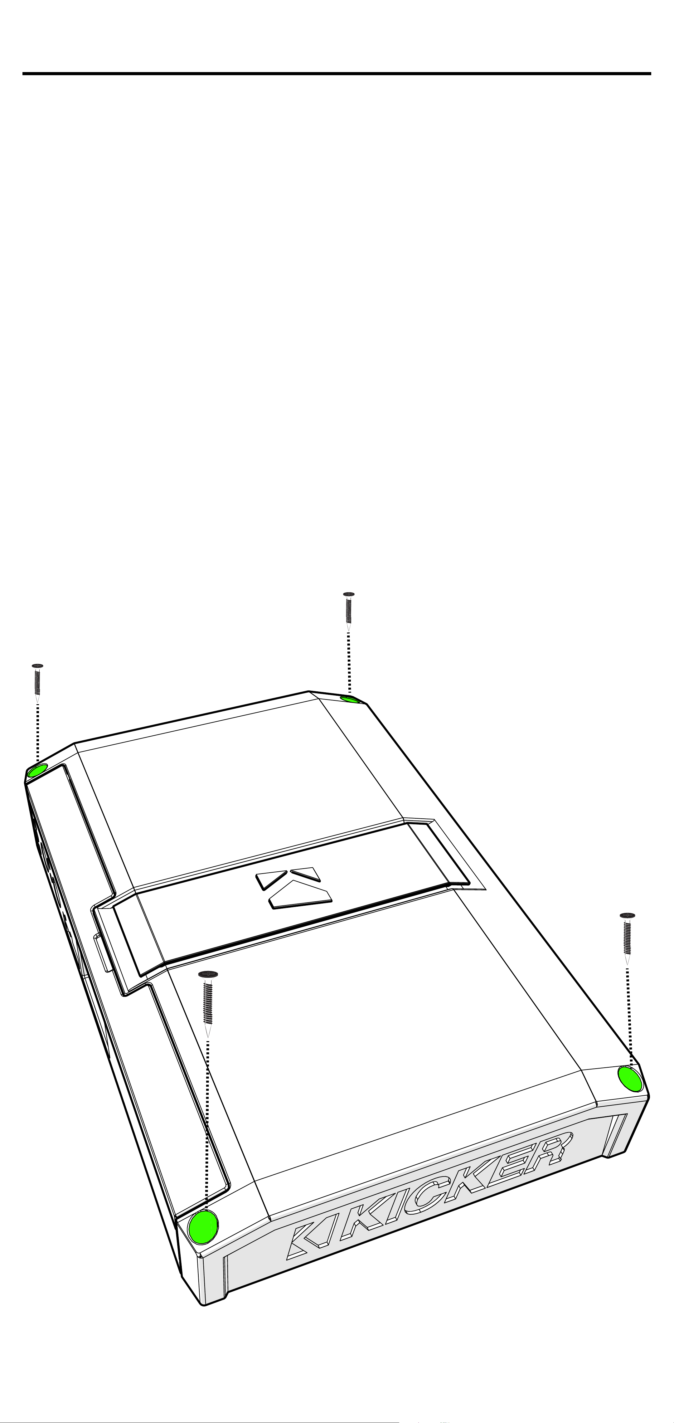
Choose a structurally sound location
to mount your KICKER amplifier. Make
sure there are no items behind the area
where the screws will be driven. Choose
a location that allows at least 4” (10cm) of
open ventilation for the amplifier. Drill four
holes using a 7/64” (3mm) bit and use the
supplied #8 screws to mount the amplifier.
7English
Page 8
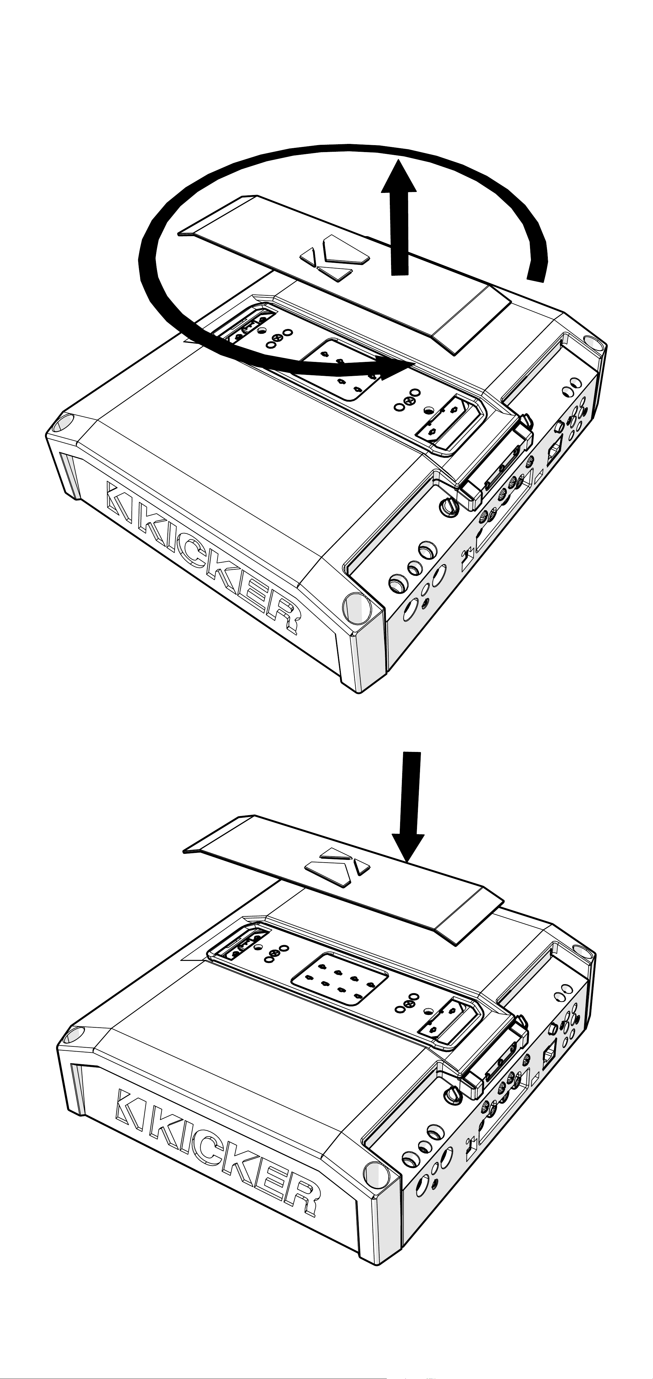
Remove and orient the magnetized KICKER
plate and badge as needed.
8English
Page 9
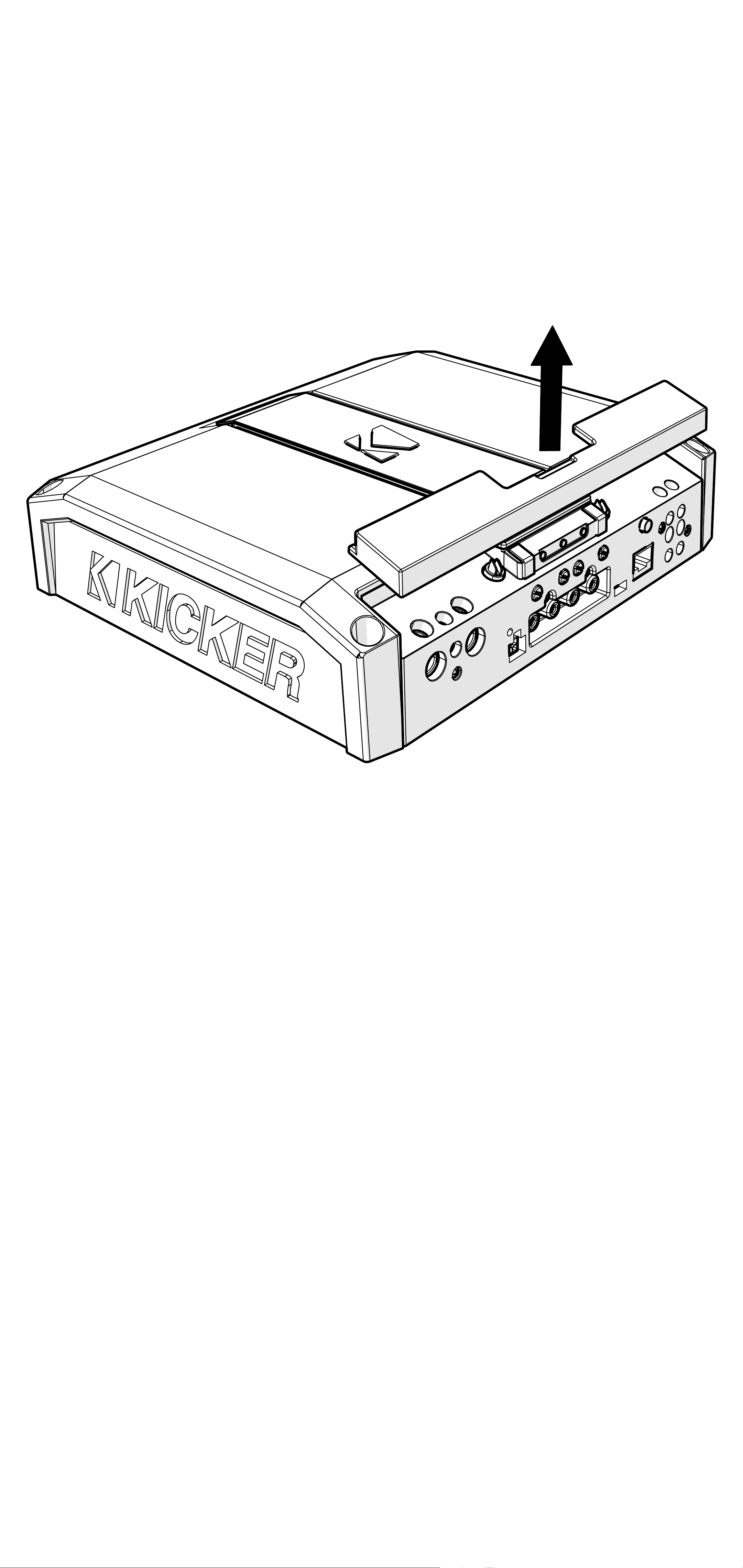
Remove the magnetized top panel cover to
access the LX amplifier’s power distribution
and speaker output terminals, as well as
gain and LED accent lighting settings.
9English
Page 10

Power Wiring
Click Here for Amplifier Install Kits
Model External Fuse (sold separately) Power/Ground Wire KICKER Wiring Kit
LX850.1 1 x 80 Ampere 4 Gauge PK4, CK4
LX1250.1 1 x 100 Ampere 1/0 Gauge PKD1
LX1650.1 1 x 150 Ampere 1/0 Gauge PKD1
LX3000.1 1 x 200 Ampere 1/0 Gauge PKD1
KICKER will provide a three-year warranty with all
LX-Series Amplifier purchases paired with a qualifying
KICKER Installation Kit*.
This extends the standard warranty by an additional year. Amplifier and Kit
must be purchased from an Authorized KICKER Dealer.
Using poor-quality, under-spec wiring kits will impede LX amplifier performance.
A superior-quality KICKER installation Kit is guaranteed to extend the life of LX amplifiers.
The new extended warranty applies only to KICKER amplifiers and accessories sold to consumers by Authorized
KICKER Dealers in the United States of America or its possessions. It also only applies to the original purchaser of
KICKER amplifiers and accessories. One warranty extension per amplifier is allowed regardless of the number of amplifier
installation kits purchased. This program does not apply to “B”-stock product or factory-refurbished product.
This offer is for a limited time, so see your local Authorized KICKER Dealer soon for details.
*U.S.A. Only | EE.UU. solamente | Nur USA | Les USA Seulement
Disconnect the vehicle’s battery to avoid an
electrical short. A good ground connection
is important. Make the ground wire short,
24” (60cm) or less and, if not conneted
to the battery, connect it to a paint-andcorrosion-free, solid metal area of the
vehicle’s chassis. Adding an additional
ground wire of this same gauge (or larger)
between the battery’s negative post and the
vehicle chassis is recommended. Keep the
audio signal cable away from factory wiring
harnesses and other power wiring. If you
need to cross this wiring, cross it at a 90
degree angle.
10English
Page 11
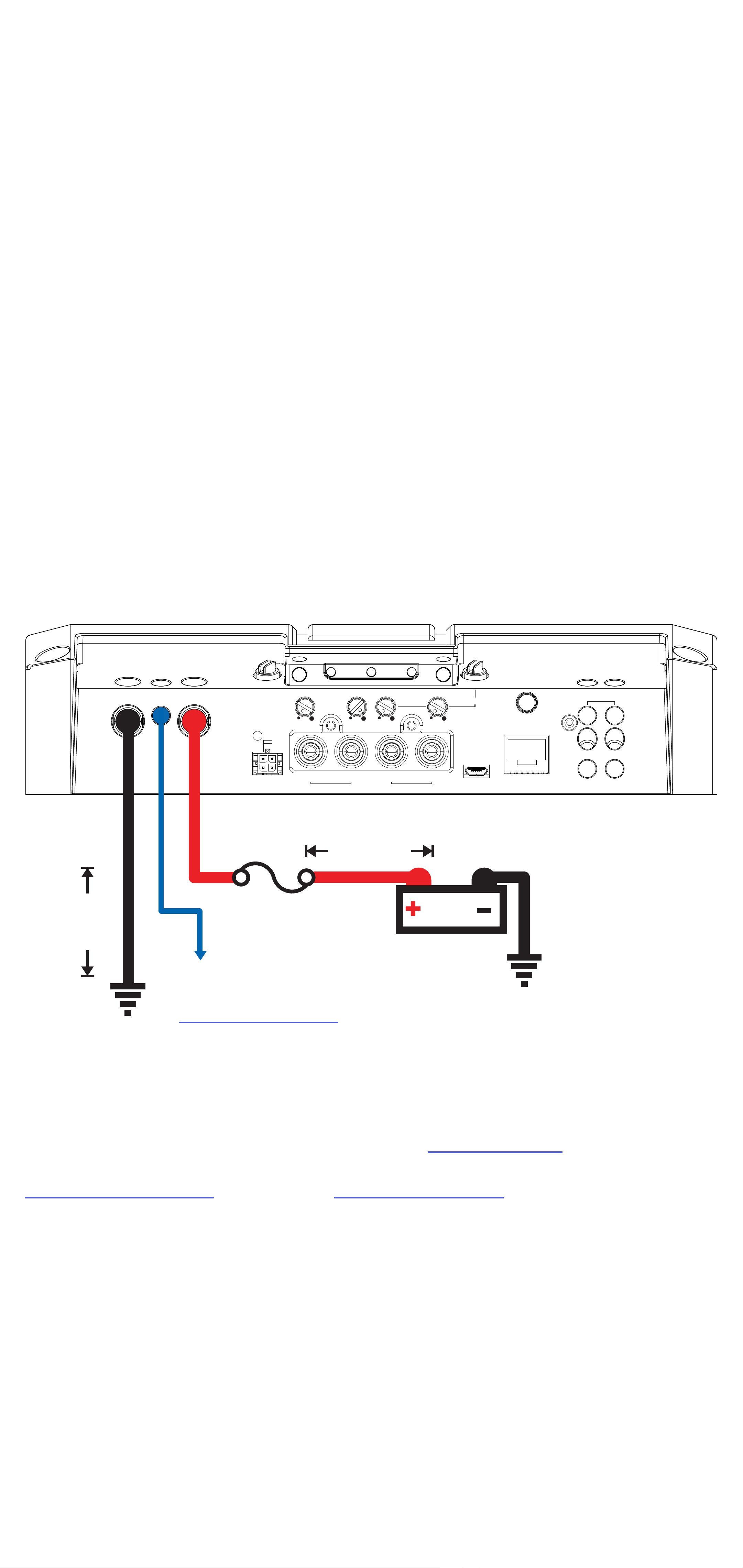
Fuse installation should be as close as
possible to the battery, and no further than
18” (45cm) of the battery, and in-line with
the power cable, which is connected to
your LX Amplifier. Make sure the power wire
is routed so that it will not be damaged,
crimped, or shorted. If you ever need to
remove the amplifier from the vehicle after it
has been installed, the ground wire should
be the last wire disconnected from the
amplifier; just the opposite as when you
installed it.
GND REM +12V
SUBSONIC X-OVER FREQ BANDWIDTH
KICK EQ+
SPEAKER
≤24”
PWR/
PRT
HI-LEVEL
INPUT
fuse
10 Hz 80 40 Hz 160 20 Hz 80 1 5
L
INPUT OUTPUT
LR R
≤18”
(45cm)
12V
REMOTE BASS
+
-
+
-
(60cm)
remote turn-on
(see page 15)
battery
ground
Pro Tip: All that’s left are KICKER
Subwoofers, and a few cables, and you’ll
have an audio upgrade that will dominate
any factory system! KICKER amplifiers
make it easy to upgrade to solid bass with
your existing or stock source unit. Ask your
dealer about KICKER upgrades.
11English
Page 12
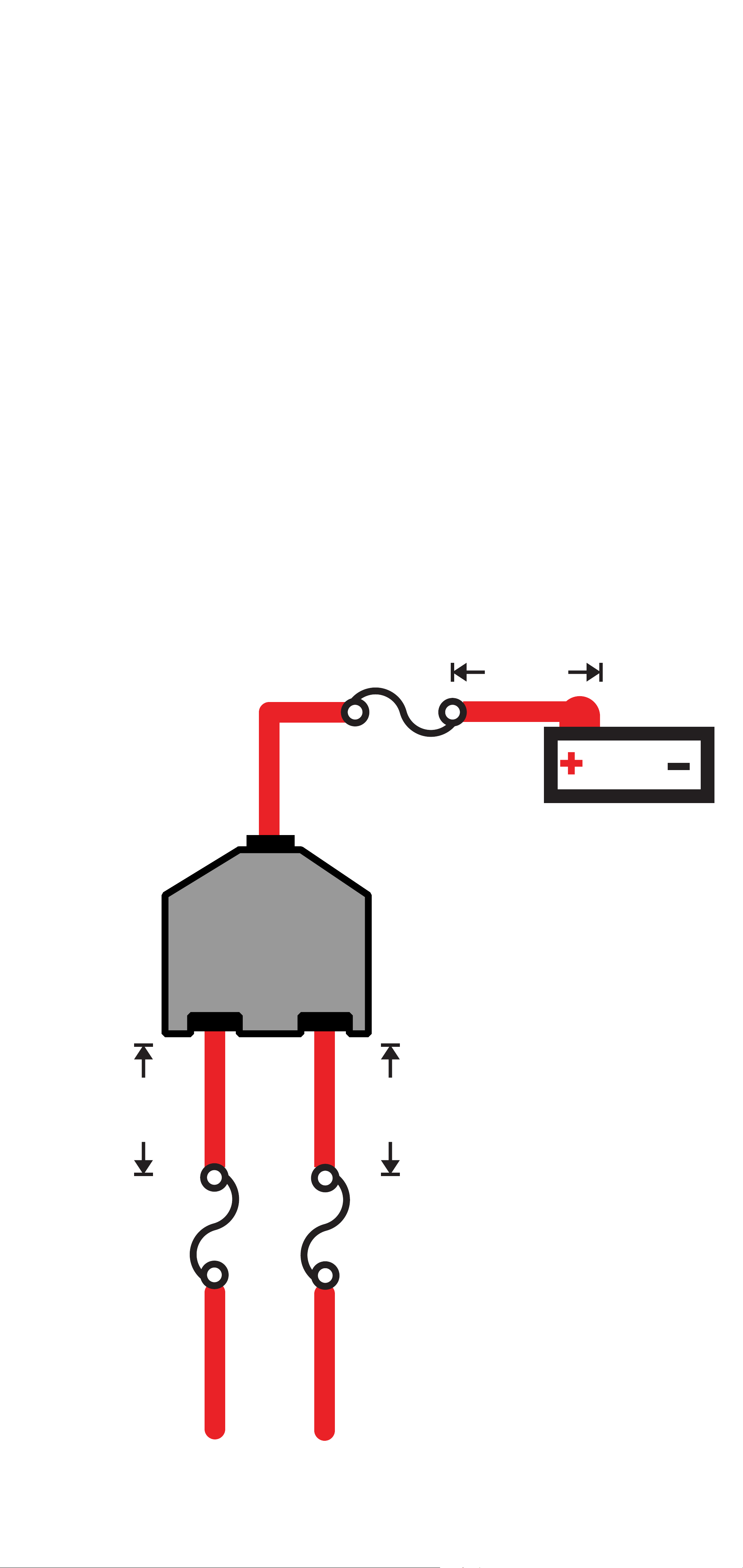
For multiple amplifier installations where
distribution blocks are used, each amplifier
should have its proper-rated fuse, or
breaker, installed between the amplifier and
the distribution block within eighteen inches
of the block, or on the distribution block if it
provides for fusing. The primary power wire
should also be fused between the battery
and distribution block, within eighteen
inches of the battery’s positive terminal, with
a fuse or breaker rated at least to the sum
of the individual amplifier’s fuse values, but
doesn’t exceed the capacity of your wiring.
≤18”
(45cm)
external fuse
power distribution block
12V
battery
≤18”
(45cm)
external fuse
≤18”
(45cm)
external fuse
to amplifiers
12English
Page 13
Input Wiring
PWR/
PRT
SUBSONIC X-OVER FREQ BANDWIDTH
KICK EQ+
10 Hz 80 40 Hz 160 20 Hz 80 1 5
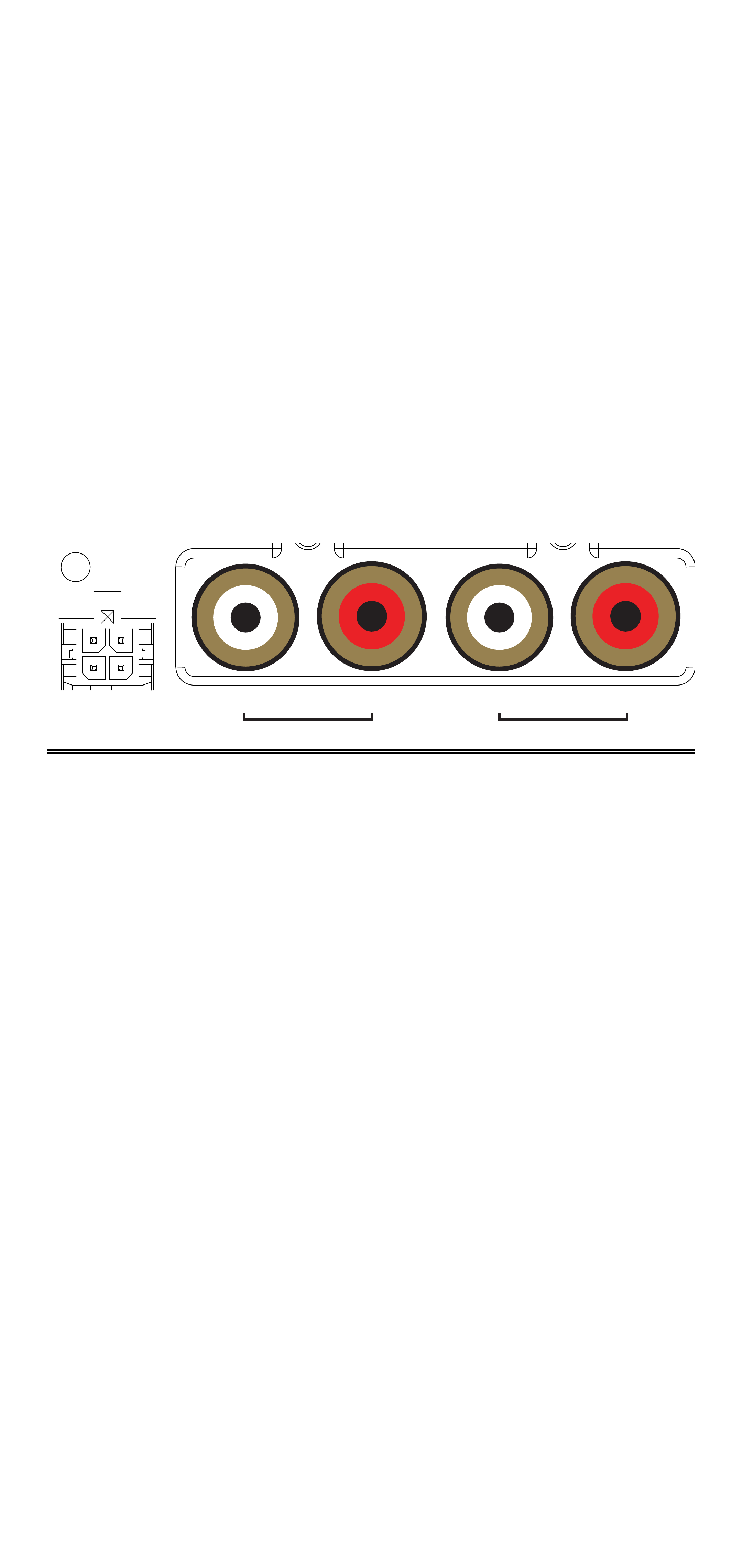
The LX-series are capable of receiving both
Low-level signals with the RCA inputs and
Hi-level signals with the Hi-Level Input wiring
harness on the front panel of the amplifier.
The LX Mono amplifiers also feature RCA
Output to conveniently chain more LX
amplifiers in your audio system.
L
HI-LEVEL
INPUT
INPUT OUTPUT
LR R
The input channel corresponding to the
wiring harness colors are:
Left: White, White/Black
Right: Grey, Grey/Black
13English
Page 14
Subwoofer Wiring
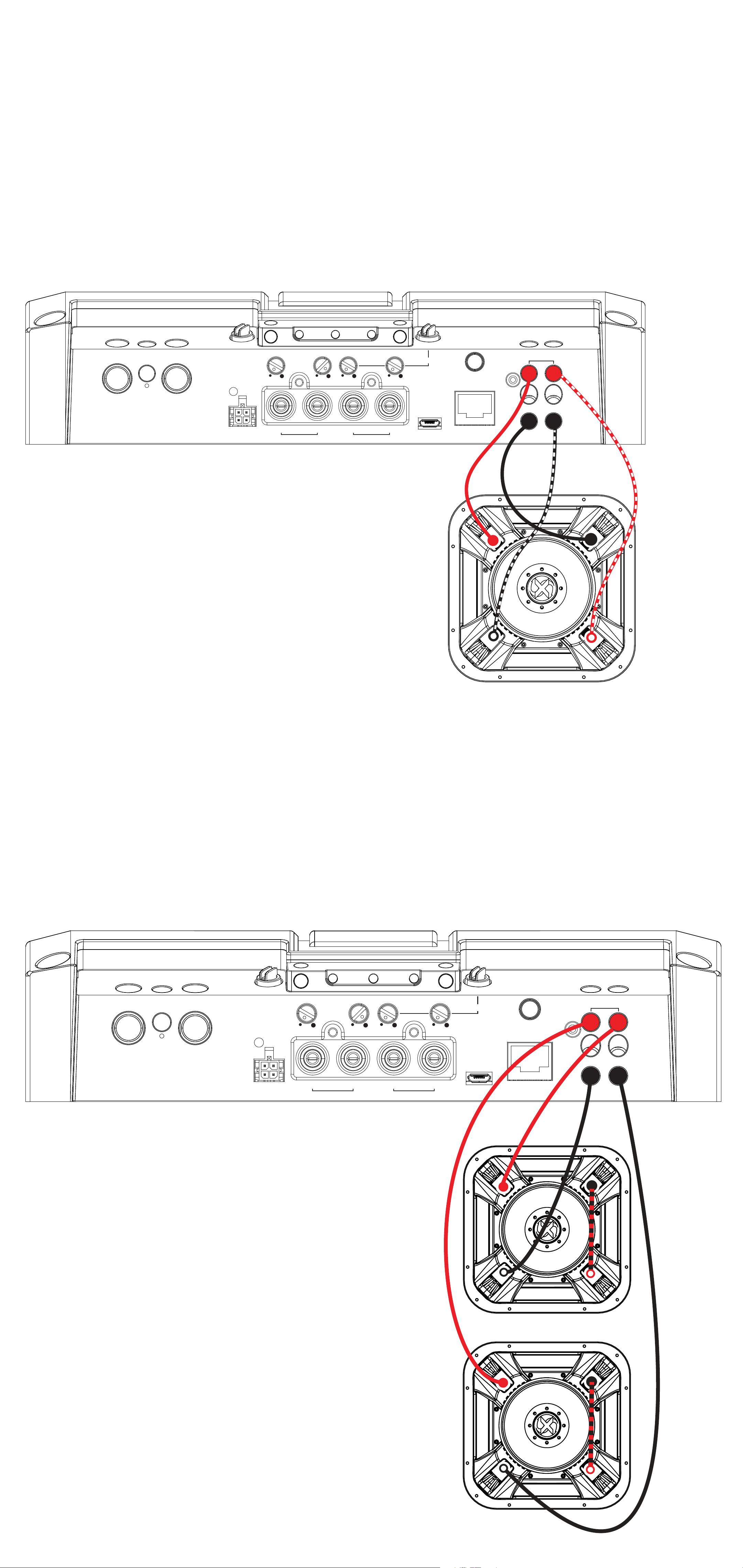
Single 2Ω Dual Voice Coil
L7X Subwoofer wired in parallel.
Final impedance of load must be a
minimum of 1Ω.
GND REM +12V
PWR/
PRT
HI-LEVEL
INPUT
SUBSONIC X-OVER FREQ BANDWIDTH
10 Hz 80 40 Hz 160 20 Hz 80 1 5
L
INPUT OUTPUT
LR R
KICK EQ+
REMOTE BASS
SPEAKER
+
-
+
-
Two 1Ω Dual Voice Coil L7X Subwoofers
wired in Series/Parallel
Final impedance of load must be a
minimum of 1Ω
GND REM +12V
PWR/
PRT
HI-LEVEL
INPUT
SUBSONIC X-OVER FREQ BANDWIDTH
10 Hz 80 40 Hz 160 20 Hz 80 1 5
L
INPUT OUTPUT
LR R
KICK EQ+
REMOTE BASS
SPEAKER
+
-
+
-
14English
Page 15
Operation
DC OFFSET
OFF
ON
L R L R L R
AMP1 AMP2 AMP3
GND REM +12V
GND REM +12V
GAIN
GAIN
MATCH
LO-PASS CENTER
SUBSONIC X-OVER FREQ BANDWIDTH
BASS
BOOST
0 dB 6
KICK EQ+
SPEAKER
DC OFFSET
OFF
ON
SPEAKER
PWR/
PRT
HI-LEVEL
INPUT
10 Hz 80 40 Hz 160 20 Hz 80 1 5
L
INPUT OUTPUT
LR R
+
-
REMOTE BASS
+
-
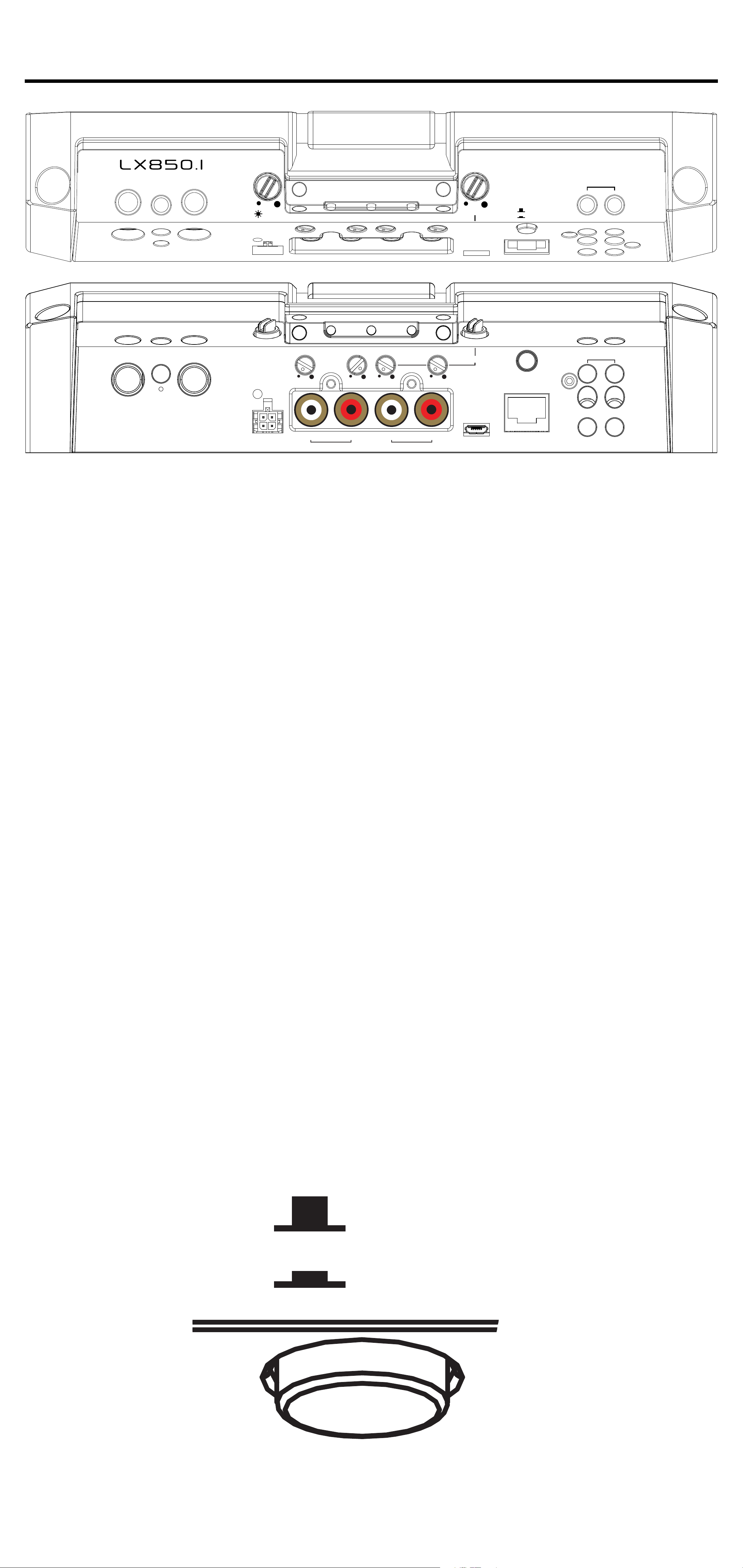
Automatic Turn-On: The LX-series offers
two different automatic turn-on modes;
+12V and DC Offset.
• Remote Turn-On: Run 18 gauge wire from the Remote
Turn-On Lead on your source unit to the REM terminal on
the LX amplifier’s end panel.
• DC Offset Turn-On: The DC Offset mode uses the HiLevel input harness to detect >2.5V DC from the Hi-Level
speaker output of the source unit when it has been turned
on. To use DC offset mode, the DC OFF/ON push button
must be in the ON or IN position. When using DC Offset
mode, the REM terminal becomes a switched +12V
output (100mA) to turn other amplifiers and devices on.
15English
Page 16

INPUT GAIN: The input gain control is
MATCH
not a volume control. It matches the output
of the source unit to the input level of
the amplifier. Maximum power out of the
amplifier is possible with the gain in the
lowest position. Incorrectly setting the gain
can result in distorted output or damage to,
and premature failure of, your speakers.
GAIN
GND REM +12V
GAIN
GAIN MATCHING: In any audio system,
the goal is to reach maximum input and
output levels without distortion or clipping.
The engineers at KICKER have taken the
guesswork, and hassle, out of matching
the output voltage of your source unit to the
amplifier with the Gain Matching feature. To
begin, you’ll need to download the KICKER
test tones from KICKER.com.
These test tones are sine waves meant to
provide a consistent signal for the amplifier
to reference. The different recording levels
are designed to give you the perfect gain
match for your application.
16English
Page 17

0dBFS: Designed for audiophile applications
to give you distortion free audio output with the
most dynamic range.
-5dBFS: Designed for normal/daily
applications, there will be less dynamic range
but higher potential audio output levels. With this
set up you can get some occasional clipping
from the amplifier.
-10dBFS: Designed only for Subwoofer
applications, there will be less dynamic range
but higher potential audio output levels. With
this set up you can get some clipping from the
amplifier.
Afterwards, use the following procedure to
accurately Gain Match your amplifier(s):
1. Disconnect the speakers from the
amplifier.
2. Set all EQ and crossover settings to flat
on your source unit.
3. Play the downloadable file from
KICKER.com
4. Turn the source unit up to the maximum
unclipped volume level. If you cannot
accurately determine this, ¾ volume is a
good starting point.
5. Increase the gain of the amplifier until
the Gain LED turns on.
6. Decrease the gain of the amplifier until
the Gain LED turns off.
17English
Page 18

To use the preferred method of setting the
input gain using a voltmeter or oscilloscope,
begin by turning off the amplifier and
disconnecting all speakers from it. Turn the
gain knob completely off (counterclockwise)
and all crossovers off, or to their least
effective setting. If a remote bass accessory
is connected to the amplifier, turn it
completely on (clockwise). Ensure all EQ
and DSP settings on the source unit such
as bass, treble, fader, seating position etc
are set to linear, flat, center, or off. Turn on
the amplifier. With an oscilloscope, probe
the signal coming from the source unit and
play a 0dB sine wave through your source
unit and increase the volume until you see
the waveform clip slightly. Turn the head unit
down one notch as this is the maximum
unclipped volume level of your source unit.
Sine wave tracks can be downloaded for
free from KICKER.com under the “Support”
tab. Use the 50Hz sine wave to set the gain
for a subwoofer and the 1kHz sine wave for
full-range speakers. Set your voltmeter or
oscilloscope to measure AC voltage. Place
the voltmeter’s probes on the amplifier’s
speaker output terminals. With the sine
wave playing, slowly turn the gain knob
clockwise and watch the AC voltage on the
voltmeter increase.
18English
Page 19

When the desired voltage is shown
(reference power chart at KICKER.com), or
you start to see the waveform square off
stop increasing the gain, turn the amplifier
off, reconnect all speakers and set the
crossovers to your desired setting. Your
gain is now set for maximum unclipped
power from the amplifier. If you increase
amplitude using settings on the source unit
or the bass boost on the amplifier it will
introduce distortion and you will need to
redo these steps.
LED Accent Lighting: Remove the top
panel cover to access the LED Accent
Lighting Controls. These also control the
LXRC lighting.
Change LED
Color
Change LED
Brightness
Press the Change LED Color button to
cycle through the available colors. Press
the Change LED Brightness to change the
intensity of the light, or to turn it off.
Available Colors:
Red Magenta Violet
Blue Light Blue Cyan
Dark Green Green Yellow
Orange White
19English
Page 20

Factory Reset: Remove the top panel
cover to access the Factory Reset button.
To restore factory settings, press and hold
the Factory Reset button for 10 seconds.
Turn the amplifier off and back on by cycling
the ignition.
Factory Reset - Press & Hold for 10 seconds
WARNING: Factory reset will reset all
settings that are controlled by LXCC to
factory (including crossover)
20English
Page 21
LO-PASS CENTER
DC OFFSET
OFF
ON
BASS
BOOST
0 dB 6
SUBSONIC X-OVER FREQ BANDWIDTH
KICK EQ+
10 Hz 80 40 Hz 160 20 Hz 80 1 5
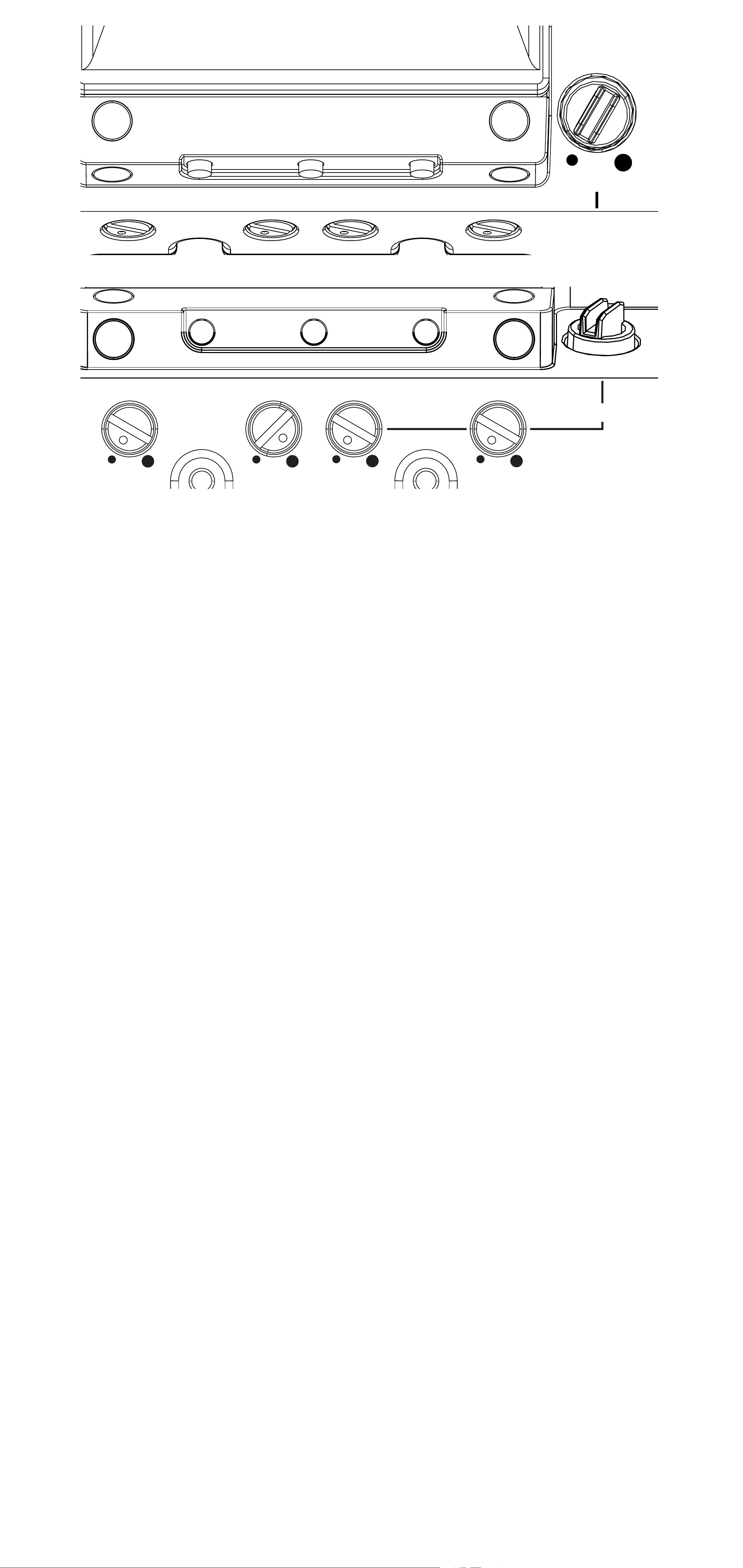
KICK EQ Parametric Bass Boost:
The BASS BOOST may be set from 0dB–
6dB. Use the FREQ setting to adjust the
center frequency from 20Hz–80Hz. Use the
BANDWIDTH setting to set the bandwidth
(Q) of the center frequency, from 1–5.
LO-PASS FREQ (Crossover Control):
The variable lo-pass crossover on the side
of the amplifier allows you to adjust the
lo-pass crossover frequency from 40Hz–
160Hz (Linkwitz-Riley, 24dB/octave).
SUBSONIC (Subsonic Filter): Use
the Subsonic filter to engage a hi-pass
crossover from 10Hz–80Hz with a 24db/
octave Linkwitz-Riley slope. This is used
to protect the subwoofer driver from overexcursion due to ultra-low frequencies,
preventing damage while ensuring your
amplifier’s power is used efficiently.
21English
Page 22

LXRC Installation
GND REM +12V
HI-LEVEL
INPUT
PWR/
PRT
SUBSONIC
X-OVER
FREQ
BANDWIDTH
KICK EQ+
+-+
-
SPEAKER
L
10Hz80
40Hz16020Hz801
5
INPUT
OUTPUT
LRR
The LXRC is a multi-function remote bass
knob that further expands the DSP features
of the LX amplifier, with access to LED
lighting changes, real-time battery input
voltage monitoring, clip output indication,
and KICKER’s proprietary SHOCwave 2.0
(Sub-Harmonic Octave Creation) algorithm.
Connect the supplied RJ-45 cable from the
back of the LXRC to the Remote Bass jack
of the LX amplifier.
REMOTE BASS
22English
Page 23
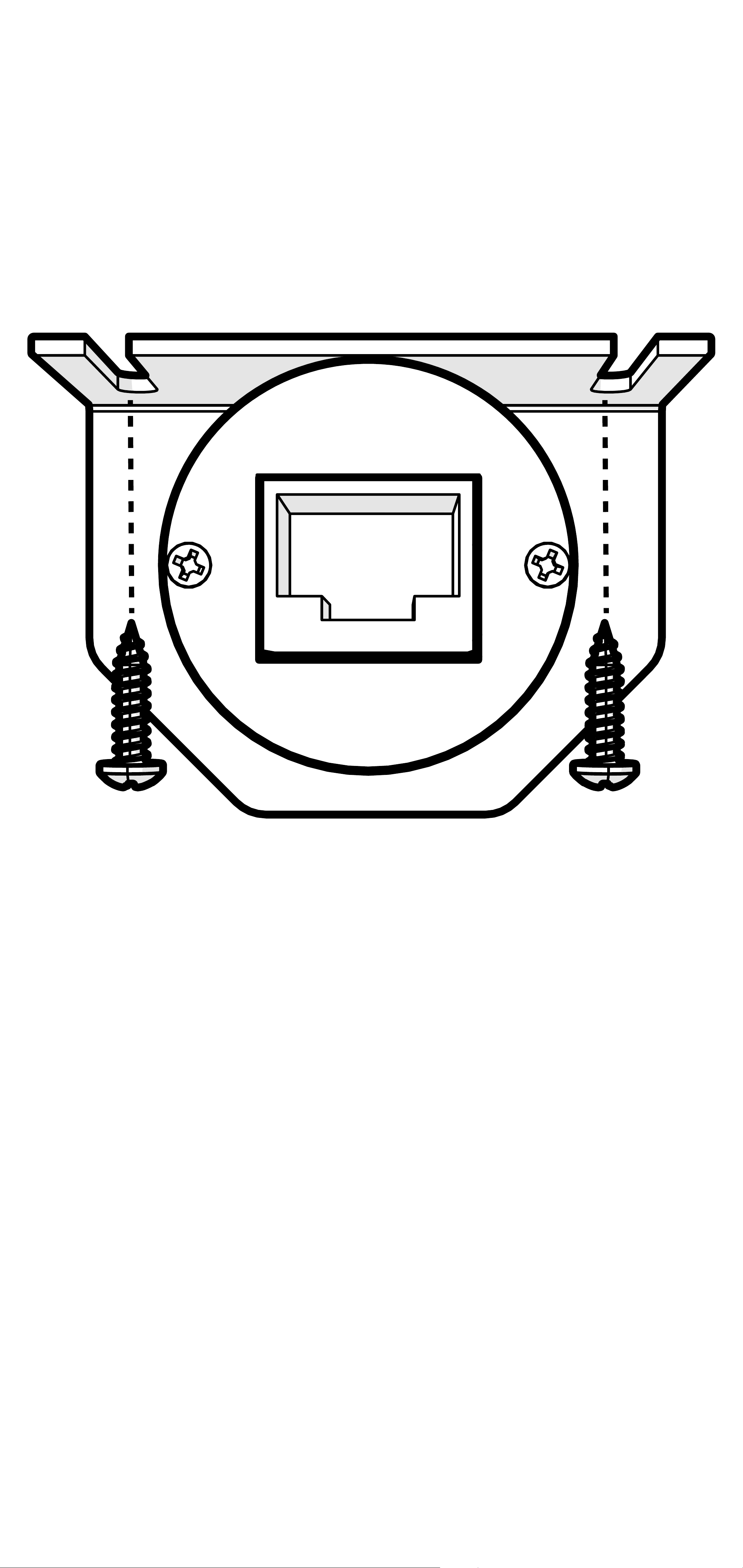
Surface Mounting: To surface mount the
LXRC, place the LXRC against a surface
and secure the mounting bracket using the
supplied screws.
23English
Page 24
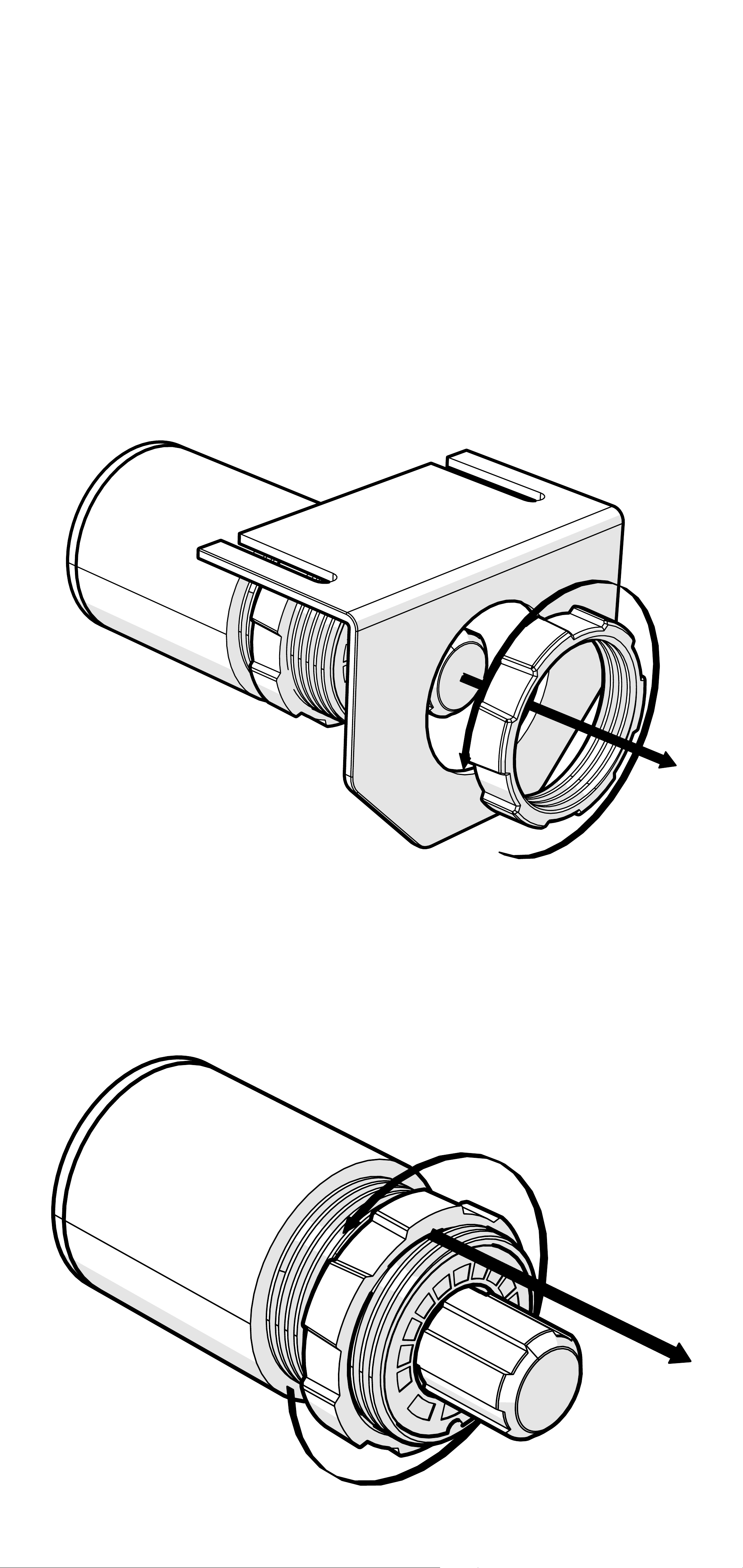
Flush Mounting: To flush mount the LXRC
behind a mounting surface, begin by cutting
a 1-inch diameter hole in the mounting
surface, being careful not to drill through
existing wiring or mechanisms.
Remove the LXRC front mounting nut and
mounting bracket.
Adjust the rear mounting nut forward to set
the protrusion of the LXRC knob.
24English
Page 25
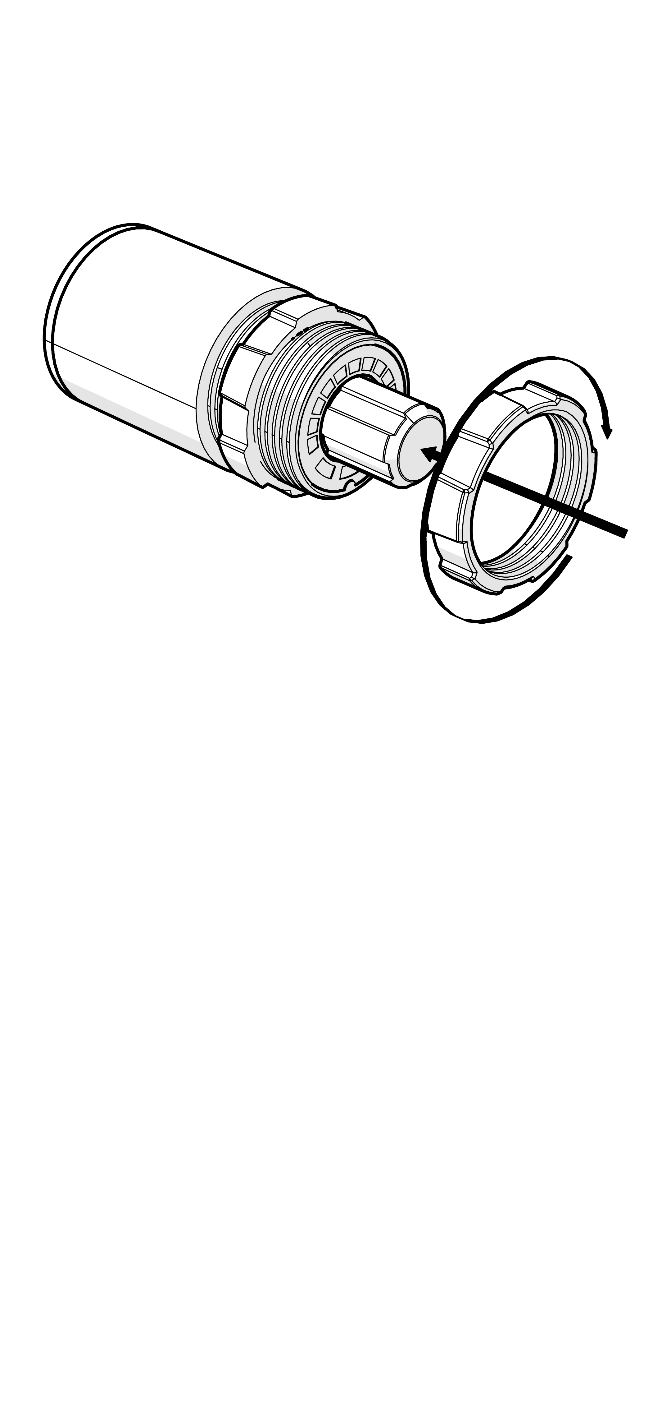
Place the LXRC through the mounting
hole, then reattach the front mounting nut
to secure the remote against the mounting
surface.
Connect the LXRC to the Remote Bass jack
of the LX amplifier.
25English
Page 26

LXRC Operation
The LXRC serves as both a rotary knob for
precise adjustments and as a multi-function
push-button to change modes, with an
illuminated LED ring to display the current
setting. You may cycle through most modes
by pressing and holding the button for <3
seconds (short-press). Once adjustments
have been made, wait for the LXRC to save
the settings and return to the default Voltage
Indication mode.
Voltage: The LXRC will default to showing
the input voltage, with the remote knob LED
ring serving as a VU meter for 11V–16V. To
enter Input Voltage Indication mode, perform
a short-press until the menu cycles, perform
no interaction for 5 seconds.
12.5
12
11.5
<11
13
13.5 14
14.5
15
15.5
16
16.5
26English
Page 27

Gain (Remote Level): The LXRC gain
control is a gain attenuator from -26dB to
0dB. This will allow you to conveniently
adjust the gain of the subwoofer channel
on the fly, with the maximum being the
gain setting you’ve selected on the LX
amplifier top panel. To enter Remote Level
mode, turn the knob while in Voltage mode,
or short-press the knob until the menu
reaches Gain.
™
SHOCwave
2.0: The SHOCwave (Sub
Harmonic Octave Creation) will restore
low frequencies that are weaker in older
recordings or lost in data compression. The
SUBWOOFER channel must be operating
with a full-range signal for this effect to work
properly. Short-Press & hold the knob until
SHOC is illuminated, then adjust the knob
to a level that is satisfactory.
Brightness: Enter the Brightness
adjustment mode by pressing and holding
the LXRC button for >3 seconds (longpress). Rotate the knob to adjust the
brightness to a satisfactory level, then
perform no action for 5 seconds and the
LXRC will return to default voltage mode.
While in voltage mode, if you double-press
the remote button the LXRC LED array will
turn on/off.
27English
Page 28

Clip: The CLIP display serves as a global
clip indicator to show when a clipped output
signal is detected. If you change your Gain
or SHOCwave setting, you may notice the
CLIP LED become active. This means your
new DSP settings have caused an output
to clip and you should reduce the gain or
compensate in some other way.
28English
Page 29

Troubleshooting
If your amplifier does not appear to be working, check the obvious things first such as blown
fuses, poor or incorrect wiring connections, incorrect setting of crossover switch and gain
controls, etc. There are Power (PWR) & Protection (PRT) LEDs on the side panel of your
KICKER LX series amplifier. Depending on the state of the amplifier and the vehicle’s charging
system, the LEDs will glow either green or red. When the green LED is lit, this indicates the
amplifier is turned on and no trouble exists.
Green LED off, no output? With a Volt Ohm Meter (VOM) check the following:
power terminal (should read +12V to +16V)
+16V)
conductivity.
Green LED on, no output? Check the following:
outputs with a “known” good speaker.
unit.
measure “AC” voltage. Use a 50Hz test tone.
Check for reversed power and ground connections
Substitute source unit with a “known” good source
Check for a signal in the RCA cable feeding the amplifier with the VOM meter set to
Remote turn-on terminal (should read +12V to
Ground terminal, for proper
RCA connections
Test speaker
+12 volt
Red (PRT) LED flickering with loud music? The red (PRT) LED indicates low battery
voltage. Check all the connections in your vehicle’s charging system. It may be necessary to
replace or charge your vehicle’s battery or replace your vehicle’s alternator.
Red (PRT) LED on, no output?
Test for proper impedance at the speaker terminals with a VOM meter set to “DC Resistance”
(see the diagrams in this manual for minimum recommended impedance and multiple
speaker wiring suggestions). Also check for adequate airflow around the amplifier.
shuts down only while vehicle is running = voltage protection circuitry is engaged. Voltage
Amplifier is very hot = thermal protection is engaged.
Amplifier
to the amplifier is not within the 6–16 volt operating range. Have the vehicle’s charging
and electrical system inspected.
circuit protection is engaged. Check for speaker wires shorted to each other or to the
vehicle chassis. Check for damaged speakers or speaker(s) operating below the minimum
recommended impedance.
No or low output?
RCA (or speaker input) and speaker output connections.
source unit, to include the volume level of any connected phones or MP3 players.
Check the balance and fader controls on source unit.
Amplifier will only play at low volume levels = short
Check the
Check the volume level on your
Alternator noise-whining sound with engine’s RPM?
(or speaker input) cable
source unit for proper grounding
set too high.
CAUTION: When jump starting the vehicle, be sure that connections made with jumper
cables are correct. Improper connections can result in blown amplifier fuses as well as the
failure of other critical systems in the vehicle.
Check the routing of RCA (or speaker input) cable
Check the gain settings and turn them down if they are
Check for damaged RCA
Check the
If you have more questions about the installation or operation of your new KICKER product,
see the Authorized KICKER Dealer where you made your purchase. For more advice on
installation, click on the SUPPORT tab on the KICKER homepage, www.KICKER.com.
Choose the TECHNICAL SUPPORT tab, choose the subject you are interested in, and then
download or view the corresponding information. Please E-mail [email protected] or call
Technical Services (405) 624-8583 for unanswered or specific questions.
29English
Page 30

LX Stereo
Specifications
Model: LX500.4
Dynamic Power [Watts] 1100W
RMS Power Output [Watts]
@ 14.4V, 4Ω stereo, ≤ 1% THD+N
@ 14.4V, 2Ω stereo, ≤ 1% THD+N
@ 14.4V, 4Ω mono, ≤ 1% THD+N
Frequency Response [Hz] 20Hz–20KHz
125W X 4 AMP1, AMP2
225W X 4 AMP1, AMP2
450W X 2
Selectable Electronic Crossover Selectable Crossover Slopes:
12dB and 24dB (Linkwitz-Riley);
12, 18 and 24dB (Butterworth)
AMP1, AMP2 Off/HP/LP/BP
(LX Control Center HP 20Hz-5KHz, LP 40Hz–5KHz)
Fader On/Off Switch Yes
Remote Bass Control No (Incompatible)
Length [in, cm] 9 7/16, 24
Height [in, cm] 2 3/8, 6
Width [in, cm] 8 7/16, 21
Signal-to-Noise Ratio [dB]
>95dB, a-weighted, re: rated power
Signal-to-Noise Ratio [dB]
Input Sensitivity Low Level: 125mV–5V
>75dB (ref: 1W output)
High Level: 1V–40V
Note: All specifications and performance figures are subject
to change. Please visit www.kicker.com for the most
current information. To get the best performance from
your new KICKER amplifier, we recommend using genuine
KICKER speakers, accessories and wiring.
30English
Page 31
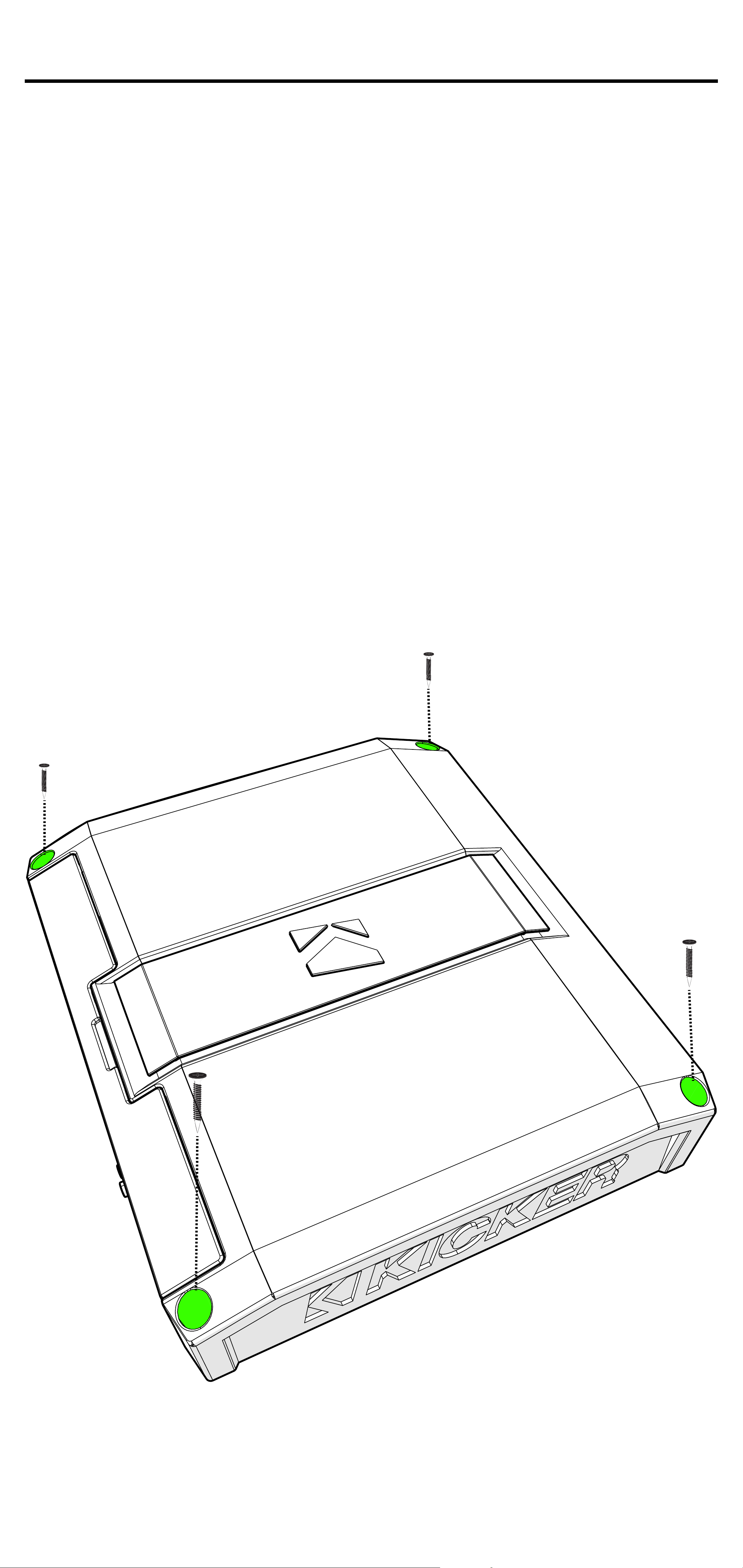
Installation
Mounting
Choose a structurally sound location
to mount your KICKER amplifier. Make
sure there are no items behind the area
where the screws will be driven. Choose
a location that allows at least 4” (10cm) of
open ventilation for the amplifier. Drill four
holes using a 7/64” (3mm) bit and use the
supplied #8 screws to mount the amplifier.
31English
Page 32
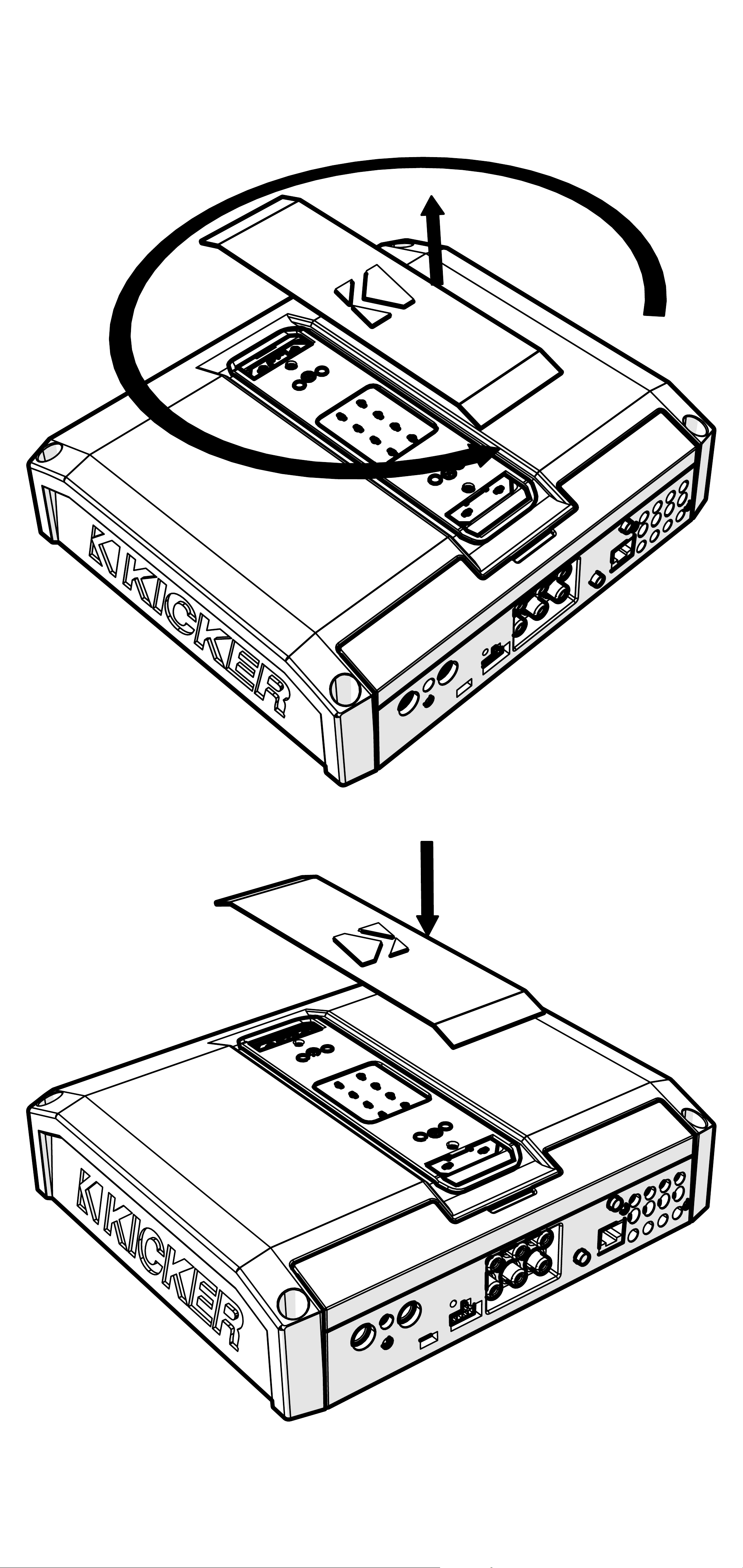
Remove and orient the magnetized KICKER
plate and badge as needed.
32English
Page 33
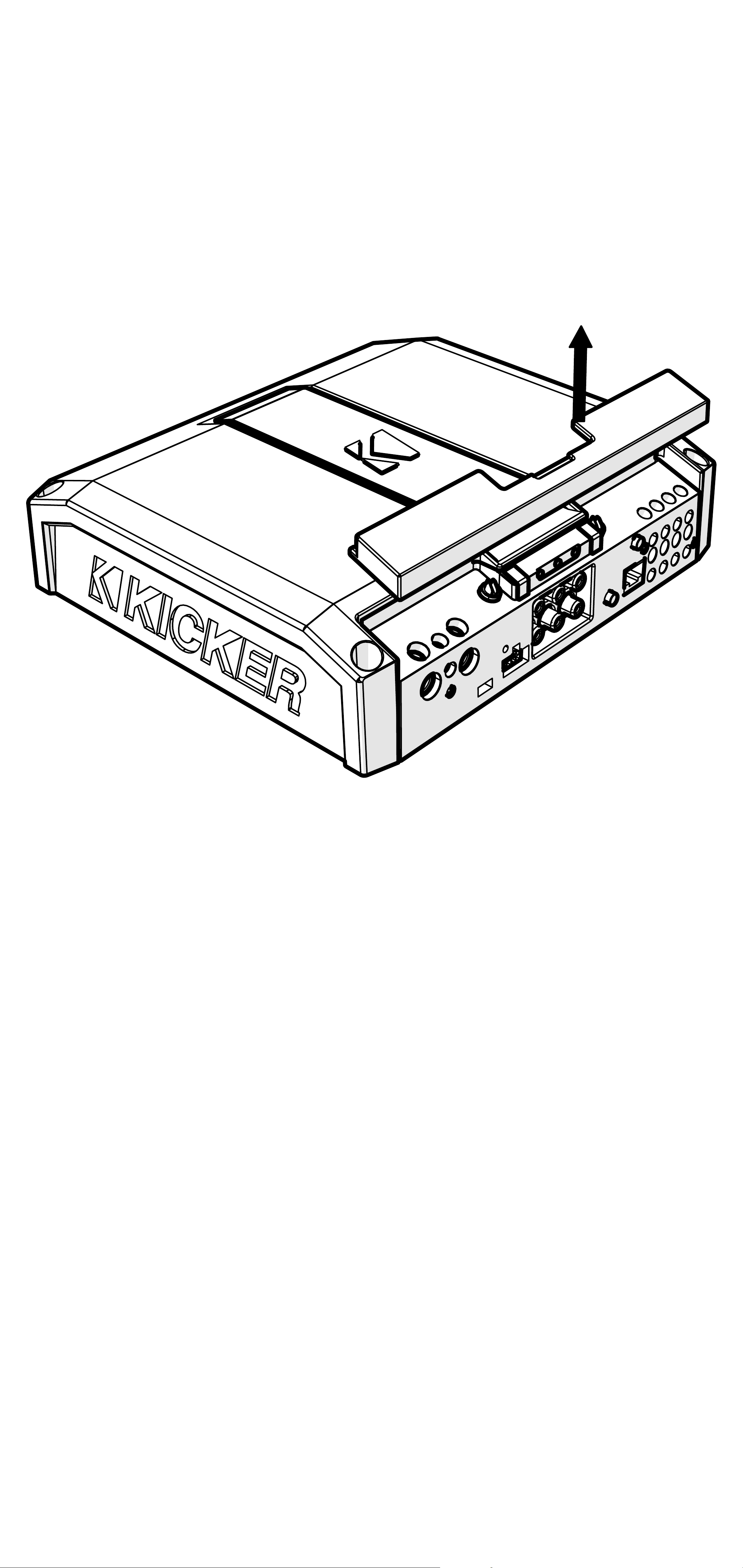
Remove the magnetized top panel cover to
access the LX amplifier’s power distribution
and speaker output terminals, as well as
gain and LED accent lighting settings.
33English
Page 34

Power Wiring
Click Here for Amplifier Install Kits
Model External Fuse (sold separately) Power/Ground Wire KICKER Wiring Kit
LX500.4 1 x 80 Ampere 4 Gauge PK4, CK4
KICKER will provide a three-year warranty with all
LX-Series Amplifier purchases paired with a qualifying
KICKER Installation Kit*.
This extends the standard warranty by an additional year. Amplifier and Kit
must be purchased from an Authorized KICKER Dealer.
Using poor-quality, under-spec wiring kits will impede LX amplifier performance.
A superior-quality KICKER installation Kit is guaranteed to extend the life of LX amplifiers.
The new extended warranty applies only to KICKER amplifiers and accessories sold to consumers by Authorized
KICKER Dealers in the United States of America or its possessions. It also only applies to the original purchaser of
KICKER amplifiers and accessories. One warranty extension per amplifier is allowed regardless of the number of amplifier
installation kits purchased. This program does not apply to “B”-stock product or factory-refurbished product.
This offer is for a limited time, so see your local Authorized KICKER Dealer soon for details.
*U.S.A. Only | EE.UU. solamente | Nur USA | Les USA Seulement
Disconnect the vehicle’s battery to avoid an
electrical short. A good ground connection
is important. Make the ground wire short,
24” (60cm) or less and, if not conneted
to the battery, connect it to a paint-andcorrosion-free, solid metal area of the
vehicle’s chassis. Adding an additional
ground wire of this same gauge (or larger)
between the battery’s negative post and the
vehicle chassis is recommended. Keep the
audio signal cable away from factory wiring
harnesses and other power wiring. If you
need to cross this wiring, cross it at a 90
degree angle.
34English
Page 35
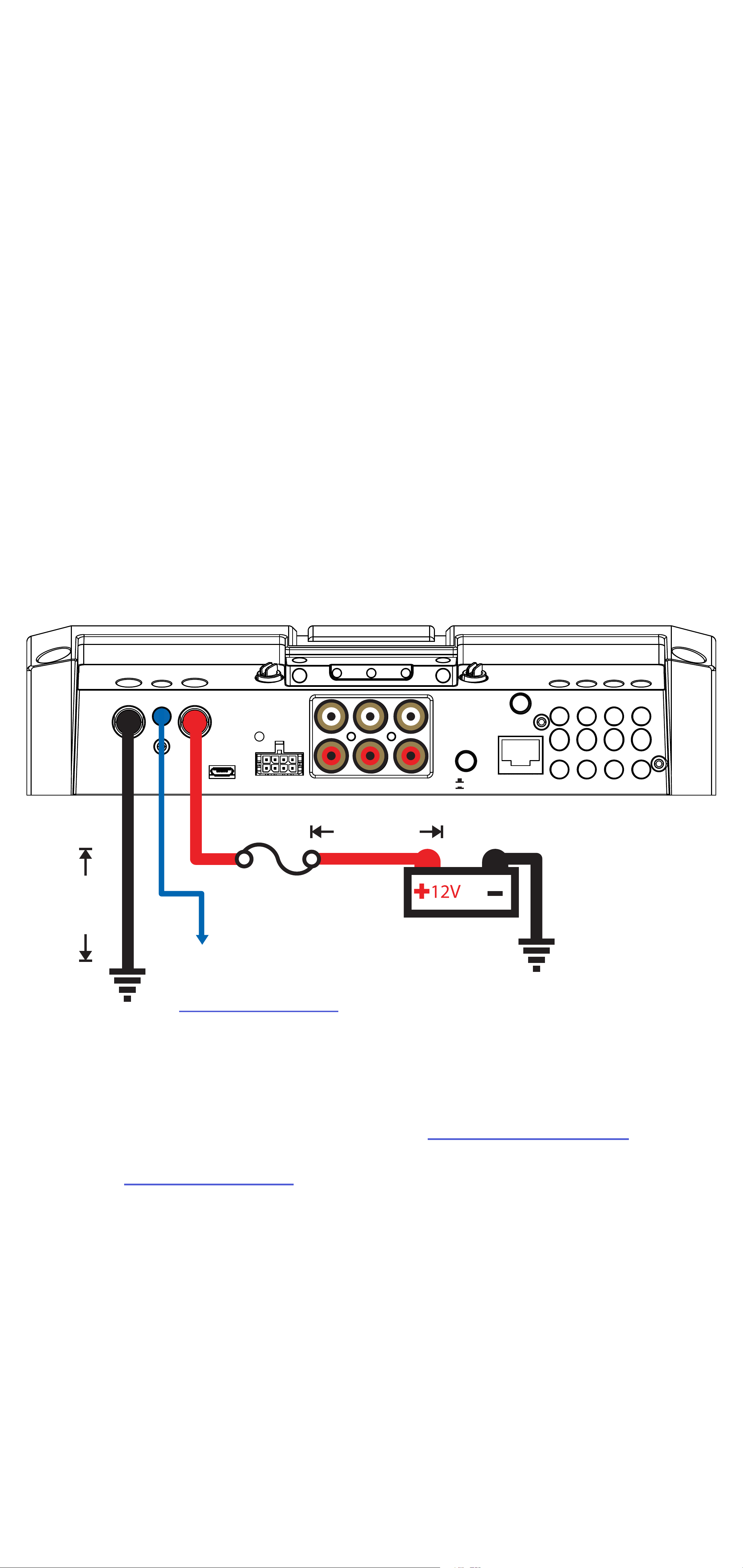
Fuse installation should be as close as
possible to the battery, and no further than
18” (45cm) of the battery, and in-line with
the power cable, which is connected to
your LX Amplifier. Make sure the power wire
is routed so that it will not be damaged,
crimped, or shorted. If you ever need to
remove the amplifier from the vehicle after it
has been installed, the ground wire should
be the last wire disconnected from the
amplifier; just the opposite as when you
installed it.
GND REM +12VGND REM +12V
BRIDGED (L+ AND R-)
≤24”
PWR/
PWR/
PRT
PRT
HI-LEVEL
HI-LEVEL
INPUT
INPUT
fuse
AMP1 AMP2 OUTPUT
AMP1 AMP2 OUTPUT
≤18”
(45cm)
L
L
FADERFADER
R
R
OFF
OFF
ON
ON
CONTROLLER
+
-
+
- -
+
+
-
(60cm)
battery
remote turn-on
ground
(see page 41)
Pro Tip: All that’s left are KS speakers,
and a few cables, and you’ll have an audio
upgrade that will dominate any factory
system! KICKER amplifiers make it easy to
upgrade to solid bass with your existing or
stock source unit. Ask your dealer about
KICKER upgrades.
35English
Page 36
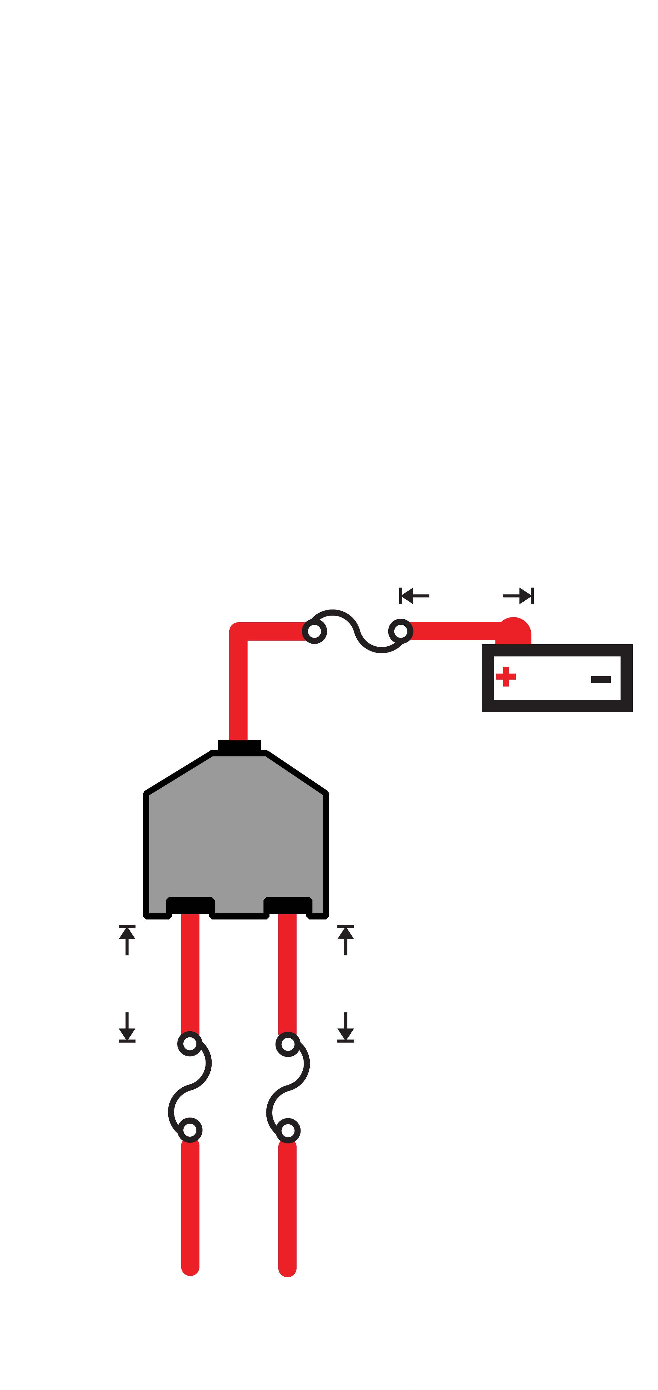
For multiple amplifier installations where
distribution blocks are used, each amplifier
should have its proper-rated fuse, or
breaker, installed between the amplifier and
the distribution block within eighteen inches
of the block, or on the distribution block if it
provides for fusing. The primary power wire
should also be fused between the battery
and distribution block, within eighteen
inches of the battery’s positive terminal, with
a fuse or breaker rated at least to the sum
of the individual amplifier’s fuse values, but
doesn’t exceed the capacity of your wiring.
≤18”
(45cm)
external fuse
power distribution block
12V
battery
≤18”
(45cm)
external fuse
≤18”
(45cm)
external fuse
to amplifiers
36English
Page 37
Input Wiring
FADERFADER
OFF
ON
OFF
ON
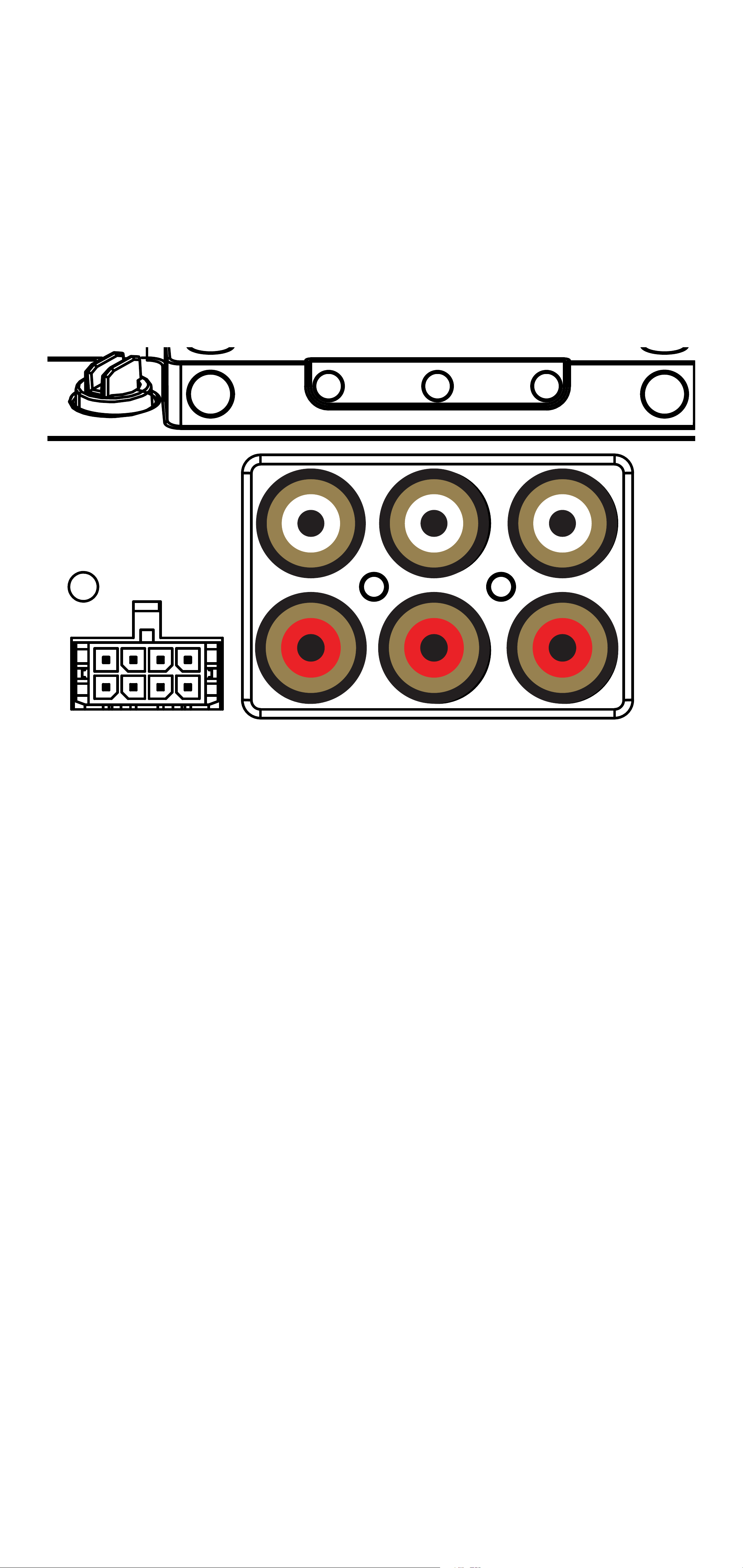
The LX-series are capable of receiving both
Low-level signals with the RCA inputs and
Hi-level signals with the Hi-Level Input wiring
harness on the front panel of the amplifier.
PWR/
PWR/
PRT
PRT
L
L
R
R
HI-LEVEL
HI-LEVEL
AMP1 AMP2 OUTPUT
AMP1 AMP2 OUTPUT
INPUT
INPUT
The input channel corresponding to the
wiring harness colors are:
AMP1 Left: White, White/Black
AMP1 Right: Grey, Grey/Black
AMP2 Left: Green, Green/Black
AMP2 Right: Purple, Purple Black
37English
Page 38
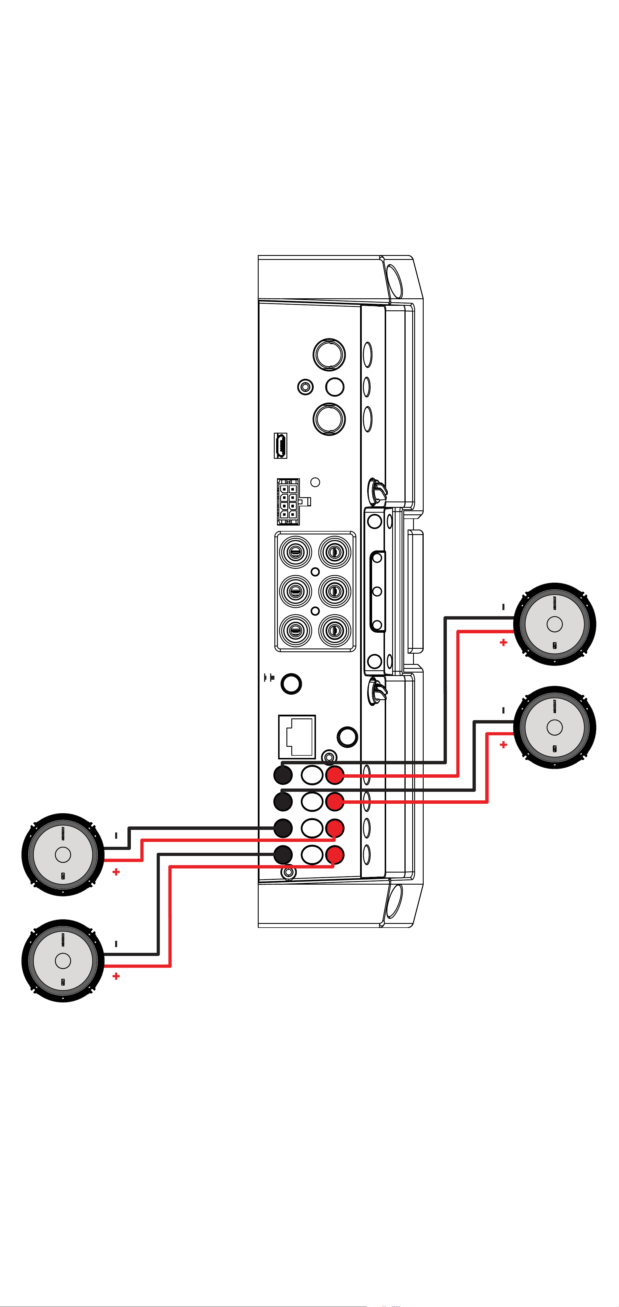
Speaker Wiring
Stereo Operation
HI-LEVEL
HI-LEVEL
INPUT
INPUT
PRT
PRT
PWR/
PWR/
GND REM +12VGND REM +12V
AMP1
AMP1 AMP2 OUTPUT
AMP1 AMP2 OUTPUT
OFF
ON
OFF
ON
R
R
FADERFADER
L
L
AMP2
CONTROLLER
-
- -
-
+
+
+
+
BRIDGED (L+ AND R-)
38English
Page 39
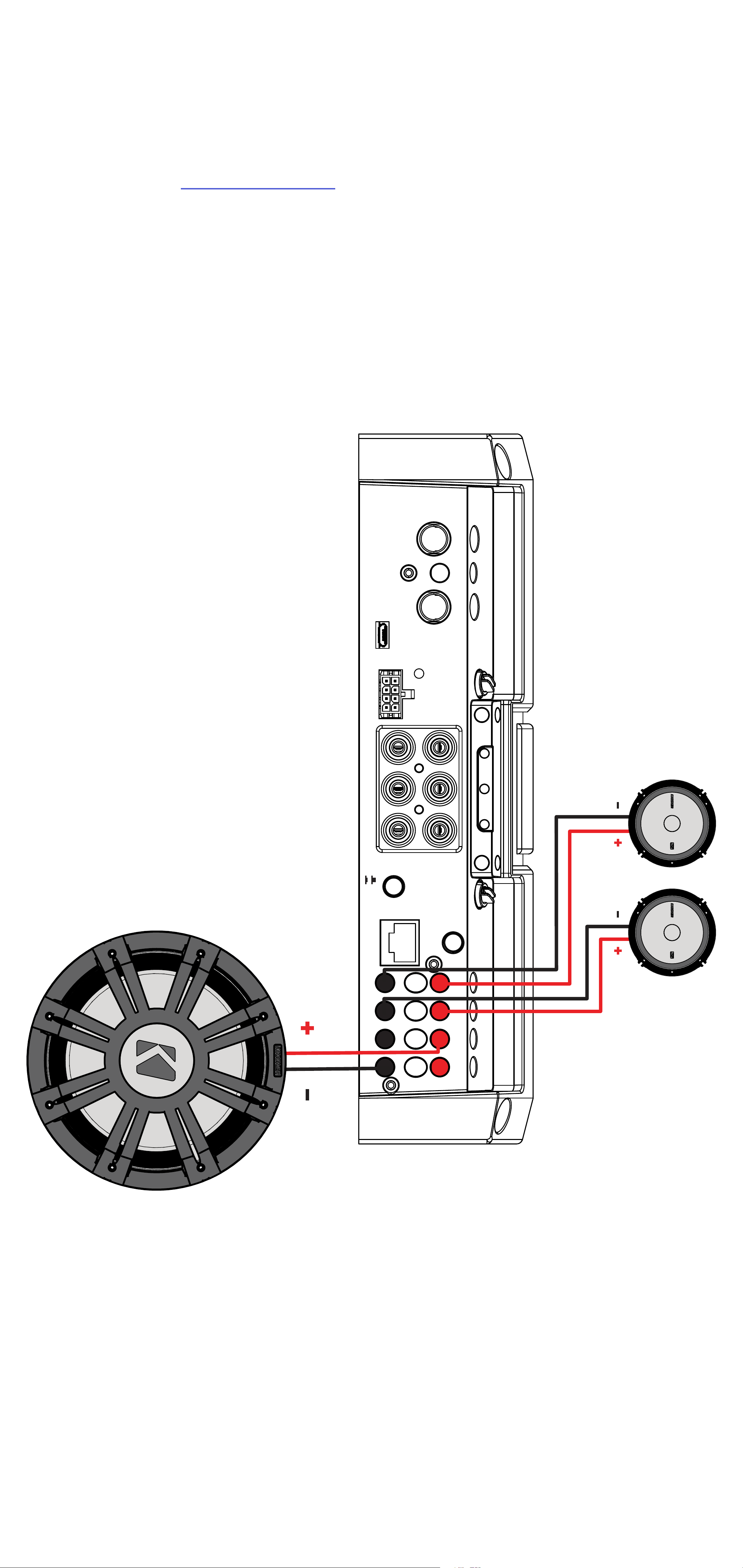
Stereo & Bridged Operation
Both stereo amplifier outputs (AMP1 & AMP2) are capable
of bridged mono output. Please refer to the RMS Power
Output in the specifications for bridged output power relative
to impedance. Use the LEFT+ and RIGHT– terminals of the
desired amplifier output to be bridged.
HI-LEVEL
HI-LEVEL
INPUT
INPUT
PRT
PRT
PWR/
PWR/
GND REM +12VGND REM +12V
AMP1
(bridged)
AMP2
AMP1 AMP2 OUTPUT
AMP1 AMP2 OUTPUT
R
R
OFF
ON
OFF
ON
CONTROLLER
FADERFADER
L
L
BRIDGED (L+ AND R-)
-
- -
-
+
+
+
+
39English
Page 40
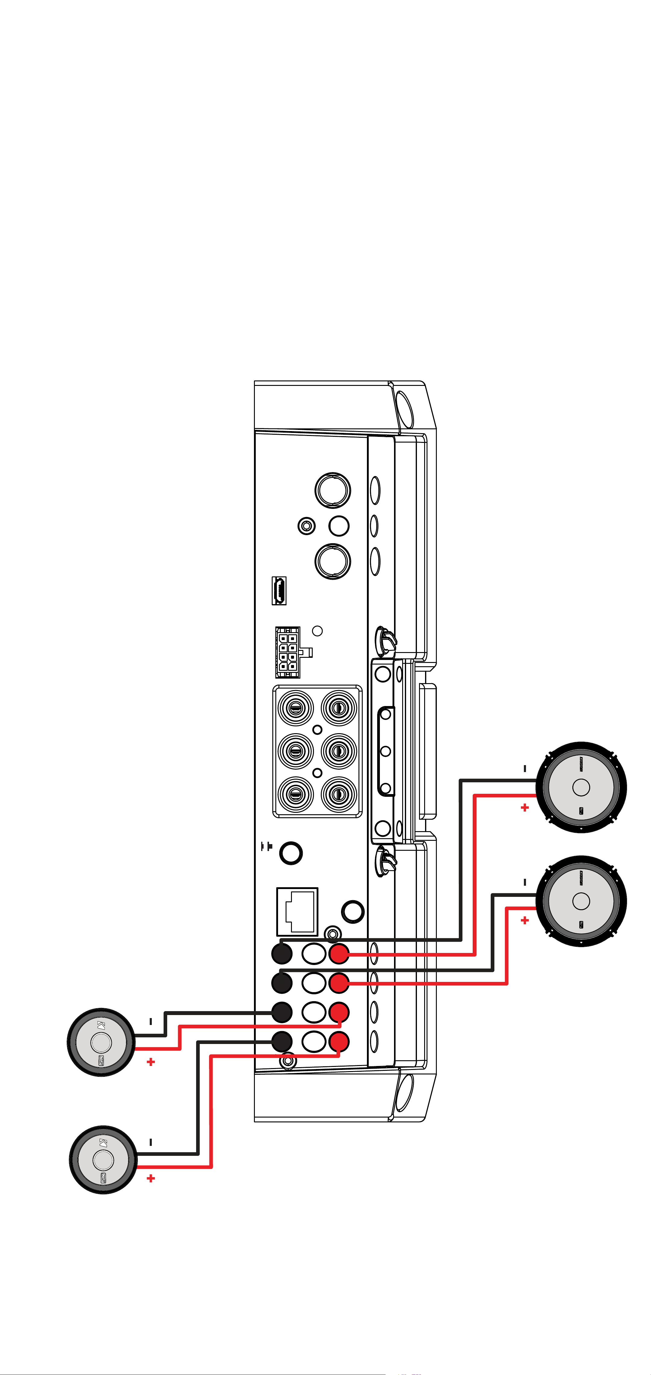
Bi-Amplification
Bi-Amplification dedicates stereo amplifier channels to
specific frequency ranges to increase efficiency and
headroom, greatly improving audio quality. As an example,
you can use one stereo output for tweeters, and another
stereo output for your mids.
HI-LEVEL
HI-LEVEL
INPUT
INPUT
PRT
PRT
PWR/
PWR/
GND REM +12VGND REM +12V
AMP1 AMP2 OUTPUT
AMP1 AMP2 OUTPUT
AMP1
R
R
L
L
AMP2
OFF
ON
OFF
ON
CONTROLLER
-
- -
FADERFADER
+
+
BRIDGED (L+ AND R-)
+
-
+
40English
Page 41
Operation
DC OFFSET
OFF
ON
L R L R L R
AMP1 AMP2 AMP3
GND
GND REM +12V
REM +12V
AMP1
AMP1
GAIN
GAIN
GAIN
GAIN
MATCH
MATCH
AMP2
AMP2
GAIN
GAIN
GAIN
GAIN
MATCH
MATCH
DC OFFSET
DC OFFSET
OFF
OFF
ON
ON
AMP1
L R L R
AMP2
GND REM +12VGND REM +12V
PWR/
PWR/
PRT
PRT
HI-LEVEL
HI-LEVEL
INPUT
INPUT
AMP1 AMP2 OUTPUT
AMP1 AMP2 OUTPUT
L
L
FADERFADER
R
R
OFF
OFF
ON
ON
CONTROLLER
BRIDGED (L+ AND R-)
+
-
+
- -
+
+
-
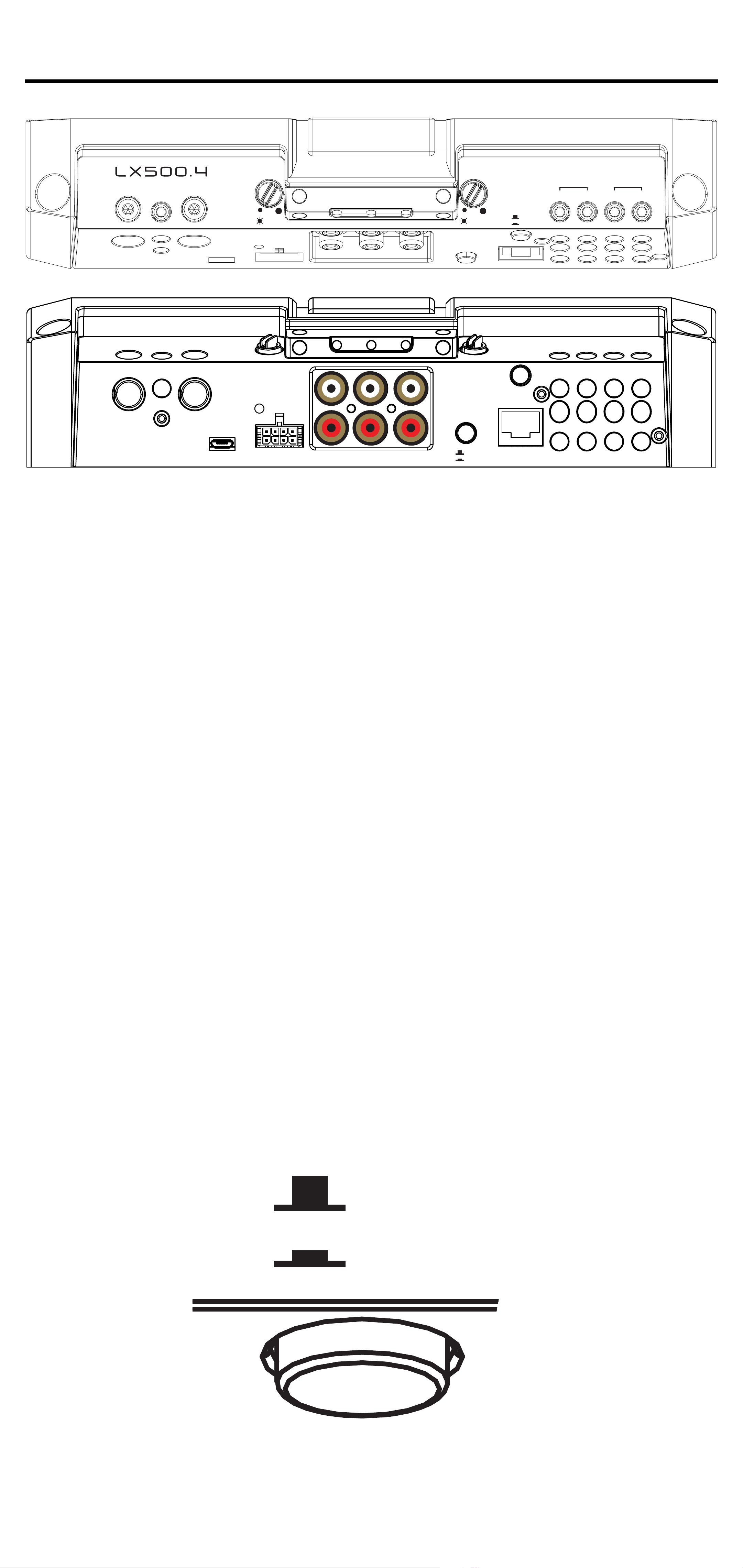
Automatic Turn-On: The LX-series offers
two different automatic turn-on modes;
+12V and DC Offset.
• Remote Turn-On: Run 18 gauge wire from the Remote
Turn-On Lead on your source unit to the REM terminal on
the LX amplifier’s end panel.
• DC Offset Turn-On: The DC Offset mode uses the HiLevel input harness to detect >2.5V DC from the Hi-Level
speaker output of the source unit when it has been turned
on. To use DC offset mode, the DC OFF/ON push button
must be in the ON or IN position. When using DC Offset
mode, the REM terminal becomes a switched +12V
output (100mA) to turn other amplifiers and devices on.
41English
Page 42

INPUT GAIN: The input gain control is
DC OFFSET
OFF
ON
DC OFFSET
OFF
ON
not a volume control. It matches the output
of the source unit to the input level of
the amplifier. Maximum power out of the
amplifier is possible with the gain in the
lowest position. Incorrectly setting the gain
can result in distorted output or damage to,
and premature failure of, your speakers.
AMP1
AMP1
GAIN
GAIN
GAIN
GAIN
MATCH
MATCH
AMP2
AMP2
GAIN
GAIN
GAIN
GAIN
MATCH
MATCH
GAIN MATCHING: In any audio system,
the goal is to reach maximum input and
output levels without distortion or clipping.
The engineers at KICKER have taken the
guesswork, and hassle, out of matching
the output voltage of your source unit to the
amplifier with the Gain Matching feature. To
begin, you’ll need to download the KICKER
test tones from KICKER.com.
These test tones are sine waves meant to
provide a consistent signal for the amplifier
to reference. The different recording levels
are designed to give you the perfect gain
match for your application.
42English
Page 43

0dBFS: Designed for audiophile applications
to give you distortion free audio output with the
most dynamic range.
-5dBFS: Designed for normal/daily
applications, there will be less dynamic range
but higher potential audio output levels. With this
set up you can get some occasional clipping
from the amplifier.
-10dBFS: Designed only for Subwoofer
applications, there will be less dynamic range
but higher potential audio output levels. With
this set up you can get some clipping from the
amplifier.
Afterwards, use the following procedure to
accurately Gain Match your amplifier(s):
1. Disconnect the speakers from the
amplifier.
2. Set all EQ and crossover settings to flat
on your source unit.
3. Play the downloadable file from
KICKER.com
4. Turn the source unit up to the maximum
unclipped volume level. If you cannot
accurately determine this, ¾ volume is a
good starting point.
5. Increase the gain of the amplifier until
the Gain LED turns on.
6. Decrease the gain of the amplifier until
the Gain LED turns off.
43English
Page 44

To use the preferred method of setting the
input gain using a voltmeter or oscilloscope,
begin by turning off the amplifier and
disconnecting all speakers from it. Turn the
gain knob completely off (counterclockwise)
and all crossovers off, or to their least
effective setting. If a remote bass accessory
is connected to the amplifier, turn it
completely on (clockwise). Ensure all EQ
and DSP settings on the source unit such
as bass, treble, fader, seating position etc
are set to linear, flat, center, or off. Turn on
the amplifier. With an oscilloscope, probe
the signal coming from the source unit and
play a 0dB sine wave through your source
unit and increase the volume until you see
the waveform clip slightly. Turn the head unit
down one notch as this is the maximum
unclipped volume level of your source unit.
Sine wave tracks can be downloaded for
free from KICKER.com under the “Support”
tab. Use the 50Hz sine wave to set the gain
for a subwoofer and the 1kHz sine wave for
full-range speakers. Set your voltmeter or
oscilloscope to measure AC voltage. Place
the voltmeter’s probes on the amplifier’s
speaker output terminals. With the sine
wave playing, slowly turn the gain knob
clockwise and watch the AC voltage on the
voltmeter increase.
44English
Page 45

When the desired voltage is shown
(reference power chart at KICKER.com), or
you start to see the waveform square off
stop increasing the gain, turn the amplifier
off, reconnect all speakers and set the
crossovers to your desired setting. Your
gain is now set for maximum unclipped
power from the amplifier. If you increase
amplitude using settings on the source unit
or the bass boost on the amplifier it will
introduce distortion and you will need to
redo these steps.
LED Accent Lighting: Remove the top
panel cover to access the LED Accent
Lighting Controls.
Change LED
Color
Change LED
Brightness
Press the Change LED Color button to
cycle through the available colors. Press
the Change LED Brightness to change the
intensity of the light, or to turn it off.
Available Colors:
Red Magenta Violet
Blue Light Blue Cyan
Dark Green Green Yellow
Orange White
45English
Page 46

Factory Reset: Remove the top panel
cover to access the Factory Reset button.
To restore factory settings, press and hold
the Factory Reset button for 10 seconds.
Turn the amplifier off and back on by cycling
the ignition.
Factory Reset - Press & Hold for 10 seconds
WARNING: Factory reset will reset all
settings that are controlled by LXCC to
factory (including crossover)
FADER INPUT Button: Turn the FADER
button ON if you are running more than a
single pair of RCA inputs to the amplifier.
Turn the AMP INPUT button(s) OFF if you
want to drive all channels from a single
input. For example, if you are using both the
AMP1 and AMP2 RCA inputs, switch the
FADER button to ON.
FADERFADER
OFF
OFF
ON
ON
CONTROLLER
46English
Page 47
LXCC
GND
REM
+12V
GND
REM
+12V
FADERFADER
OFFONOFF
ON
BRIDGED (L+ AND R-)
HI-LEVEL
INPUT
PWR/
PRT
R
L
AMP1
AMP2
OUTPUT
HI-LEVEL
INPUT
PWR/
PRT
R
L
AMP1
AMP2
OUTPUT
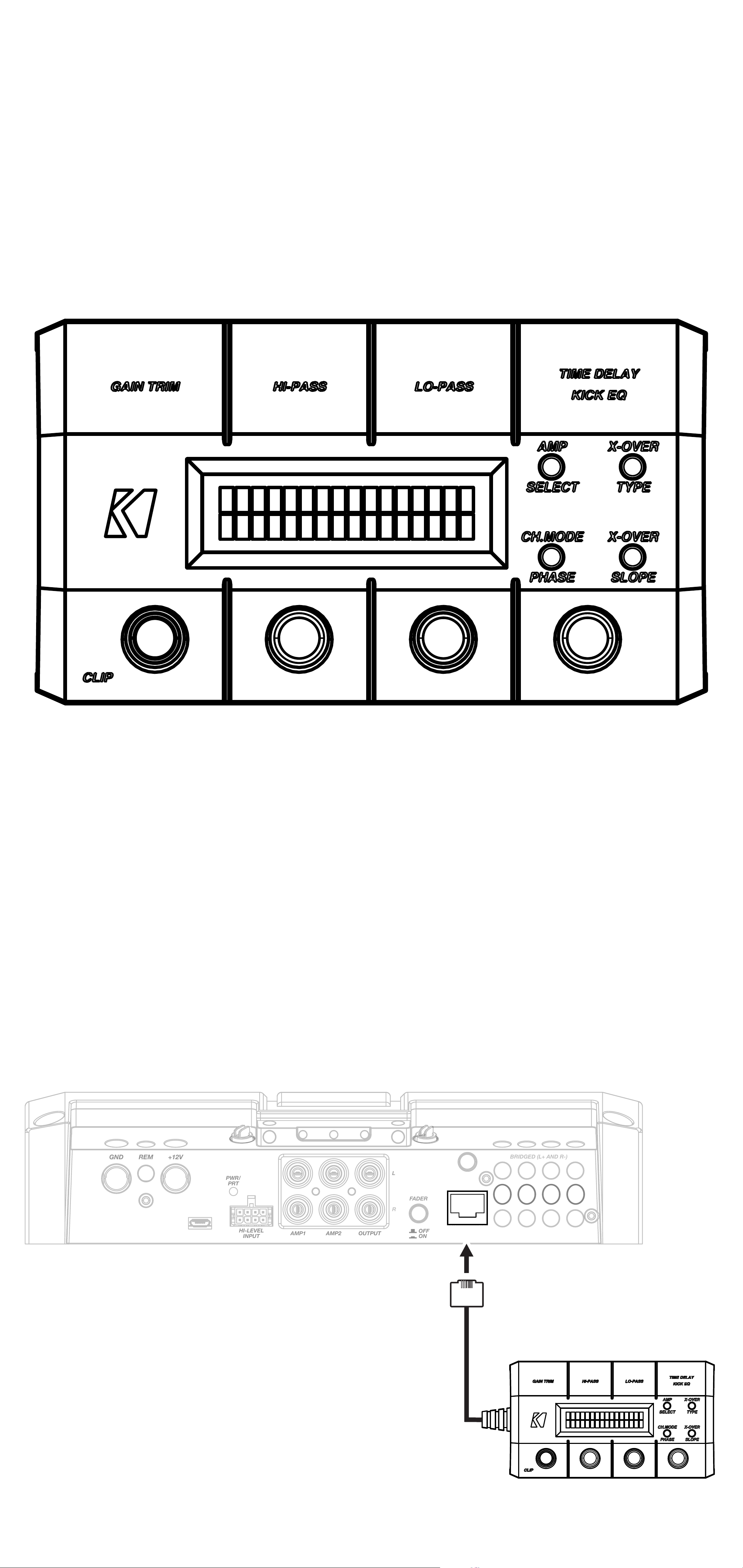
The LXCC is a Control Center that grants
access to the expanded DSP functions of
the LX amplifier, allowing you to fine-tune
your LX with ease.
Once your LX amplifier has been installed,
begin by connecting the RJ-45 cable of
the LXCC to the Controller/Remote Bass
input of the LX amplifier. The center display
will immediately show real-time amplifier
information, including amp model, amp
temperature, and supplied voltage.
CONTROLLER
47English
Page 48

GAIN TRIM: Push the Gain Trim knob to
open Gain Trim settings. Push the knob
again or the Amp Select button to select the
amplifier channel being modified. You can
cut by -9dB or boost by +3dB per amplified
section (AMP1 & AMP2). This allows you to
make minor adjustments to levels, helping
to match outputs, such as cutting your
tweeter channels, while boosting the mids.
CLIP: The CLIP indicator will illuminate
when the amplifier output is above the
clipping threshold. This only applies to the
amplifier channel currently selected (AMP
SELECT). If you change your Gain, Bass
Boost or SHOCwave setting, you may
notice the CLIP LED become active. This
means your new DSP settings have caused
an output to clip and you should reduce the
gain or compensate in some other way.
HI-PASS | LO-PASS: Push the HI-PASS
or LO-PASS knob to open the crossover
settings. Push the AMP SELECT button to
select the amplifier channel being modified.
The display will show the amplifier channel
being modified, the current crossover (FR:
Full-Range, HP: Hi-Pass, LP: Lo-Pass, BP:
Band-Pass), and the crossover point.
48English
Page 49

Use the knobs to set your crossover points,
between 20Hz–5kHz HP/BP and 40Hz–
5kHz LP for full-range channels.
X-OVER TYPE: Select the amplifier
channel for which you’d like to change
the crossover type. Press the X-OVER
TYPE button to choose Linkwitz-Riley or
Butterworth. Each amplifier channel may
have its own crossover type.
X-OVER SLOPE: Select the amplifier
channel for which you’d like to change the
crossover slope. Press the X-OVER SLOPE
button to choose between the available
slope options. Each amplifier channel may
have its own crossover slope. The available
slopes are - Linkwitz-Riley: 24dB, 12dB
Butterworth: 24dB, 18dB, 12dB
TIME DELAY: The Time Delay will delay
the left channel of the stereo outputs up
to 10ms, in increments of 0.1ms. This will
allow you to set the center stage according
to your preferences and listening position.
Channel Mode | Phase: Use the Channel
Mode button with a full-range stereo
amplifier channel to change the selected
channel output to stereo, L+R Summed, or
L-R Summed.
49English
Page 50

Troubleshooting
If your amplifier does not appear to be working, check the obvious things first such as blown
fuses, poor or incorrect wiring connections, incorrect setting of crossover switch and gain
controls, etc. There are Power (PWR) & Protection (PRT) LEDs on the side panel of your
KICKER LX series amplifier. Depending on the state of the amplifier and the vehicle’s charging
system, the LEDs will glow either green or red. When the green LED is lit, this indicates the
amplifier is turned on and no trouble exists.
Green LED off, no output? With a Volt Ohm Meter (VOM) check the following:
power terminal (should read +12V to +16V)
+16V)
conductivity.
Green LED on, no output? Check the following:
outputs with a “known” good speaker.
unit.
measure “AC” voltage. Use a 50Hz test tone.
Check for reversed power and ground connections
Substitute source unit with a “known” good source
Check for a signal in the RCA cable feeding the amplifier with the VOM meter set to
Remote turn-on terminal (should read +12V to
Ground terminal, for proper
RCA connections
Test speaker
+12 volt
Red (PRT) LED flickering with loud music? The red (PRT) LED indicates low battery
voltage. Check all the connections in your vehicle’s charging system. It may be necessary to
replace or charge your vehicle’s battery or replace your vehicle’s alternator.
Red (PRT) LED on, no output?
Test for proper impedance at the speaker terminals with a VOM meter set to “DC Resistance”
(see the diagrams in this manual for minimum recommended impedance and multiple
speaker wiring suggestions). Also check for adequate airflow around the amplifier.
shuts down only while vehicle is running = voltage protection circuitry is engaged. Voltage
Amplifier is very hot = thermal protection is engaged.
Amplifier
to the amplifier is not within the 6–16 volt operating range. Have the vehicle’s charging
and electrical system inspected.
circuit protection is engaged. Check for speaker wires shorted to each other or to the
vehicle chassis. Check for damaged speakers or speaker(s) operating below the minimum
recommended impedance.
No or low output?
RCA (or speaker input) and speaker output connections.
source unit, to include the volume level of any connected phones or MP3 players.
Check the balance and fader controls on source unit.
Amplifier will only play at low volume levels = short
Check the
Check the volume level on your
Alternator noise-whining sound with engine’s RPM?
(or speaker input) cable
source unit for proper grounding
set too high.
CAUTION: When jump starting the vehicle, be sure that connections made with jumper
cables are correct. Improper connections can result in blown amplifier fuses as well as the
failure of other critical systems in the vehicle.
Check the routing of RCA (or speaker input) cable
Check the gain settings and turn them down if they are
Check for damaged RCA
Check the
If you have more questions about the installation or operation of your new KICKER product,
see the Authorized KICKER Dealer where you made your purchase. For more advice on
installation, click on the SUPPORT tab on the KICKER homepage, www.KICKER.com.
Choose the TECHNICAL SUPPORT tab, choose the subject you are interested in, and then
download or view the corresponding information. Please E-mail [email protected] or call
Technical Services (405) 624-8583 for unanswered or specific questions.
50English
Page 51

LX Multi-Channel
Specifications
Model: LX1200.5 LX1300.7
Dynamic Power [Watts] 1500W 1500W
RMS Power Output [Watts]
@ 14.4V, 4Ω stereo, ≤ 1% THD+N
@ 14.4V, 2Ω stereo, ≤ 1% THD+N
@ 14.4V, 4Ω mono, ≤ 1% THD+N
@ 14.4V, 2Ω mono, ≤ 1% THD+N
125W X 4 AMP1, AMP2
175W X 4 AMP1, AMP2
350W X 2 AMP1, AMP2;
300W X 1 SUB
550W X 1 SUB
125W X 4 AMP1, AMP2; 65W X 2 AMP3
150W X 4 AMP1, AMP2; 65W X 2 AMP3
250W X 2 AMP1, AMP2;
130W X 1 AMP3; 300W X 1 SUB
550W X 1 SUB
@ 14.4V, 1Ω mono, ≤ 1% THD+N
700W X 1 SUB
700W X 1 SUB
Specifications Common to All Models
Frequency Response [Hz] Full-Range 20Hz–20KHz, SUB Channel 10Hz–160KHz
Selectable Electronic Crossover Selectable Crossover Slopes:
12dB and 24dB (Linkwitz-Riley);
12, 18 and 24dB (Butterworth)
AMP1, AMP2, AMP3 Off/HP/LP/BP
(LX Control Center HP 20Hz-5KHz, LP 40–5KHz)
SUB LP (LX Control Center LP 10Hz–160Hz)
Parametric Bass Boost Yes, LX Control Center Only, 0 – +6dB,
Variable Center Frequency 20–80 Hz, Variable Bandwidth 1–5
Fader On/Off Switch AMP2, AMP3, SUB
Variable Subsonic Filter Selectable Slope, Variable Hi-Pass 10–80Hz
Remote Bass Control Yes (Included)
Length [in, cm] 12 5/8, 32
Height [in, cm] 2 3/8, 6
Width [in, cm] 8 7/16, 21
Signal-to-Noise Ratio [dB]
Signal-to-Noise Ratio [dB]
Input Sensitivity Low Level: 125mV–5V
>95dB, a-weighted, re: rated power
>75dB (ref: 1W output)
High Level: 1V–40V
Note: All specifications and performance figures are subject
to change. Please visit www.kicker.com for the most
current information. To get the best performance from
your new KICKER amplifier, we recommend using genuine
KICKER speakers, accessories and wiring.
51English
Page 52
Installation
Mounting
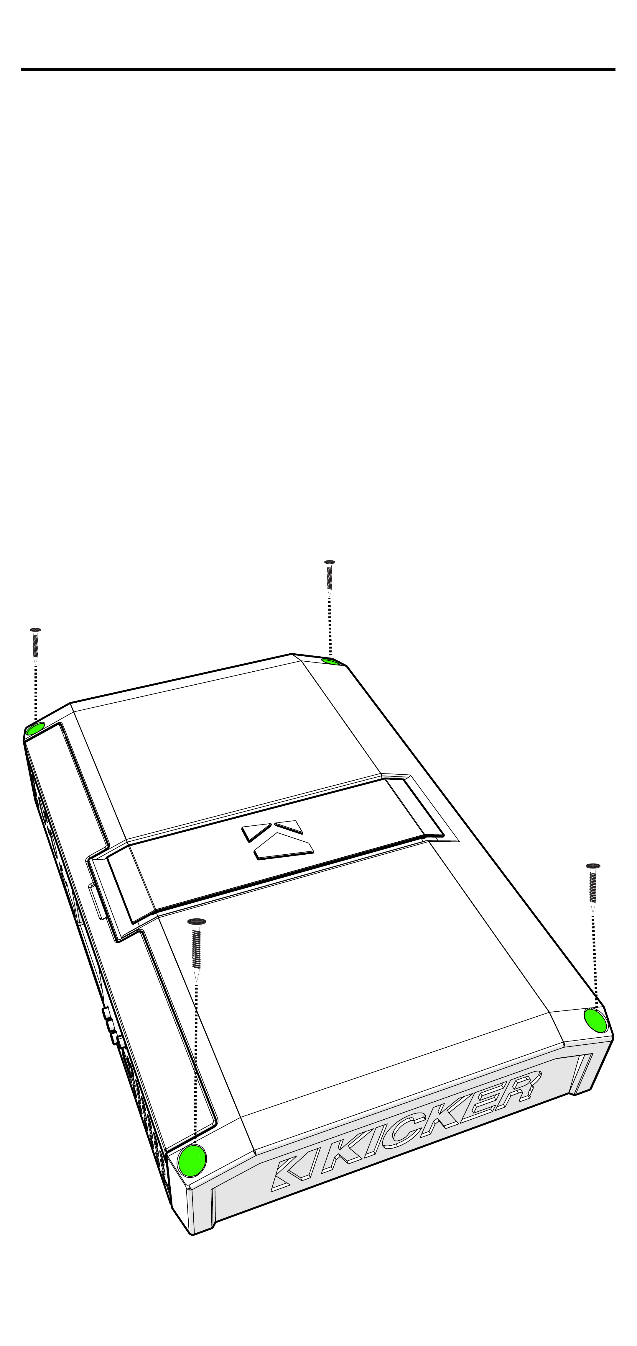
Choose a structurally sound location
to mount your KICKER amplifier. Make
sure there are no items behind the area
where the screws will be driven. Choose
a location that allows at least 4” (10cm) of
open ventilation for the amplifier. Drill four
holes using a 7/64” (3mm) bit and use the
supplied #8 screws to mount the amplifier.
52English
Page 53
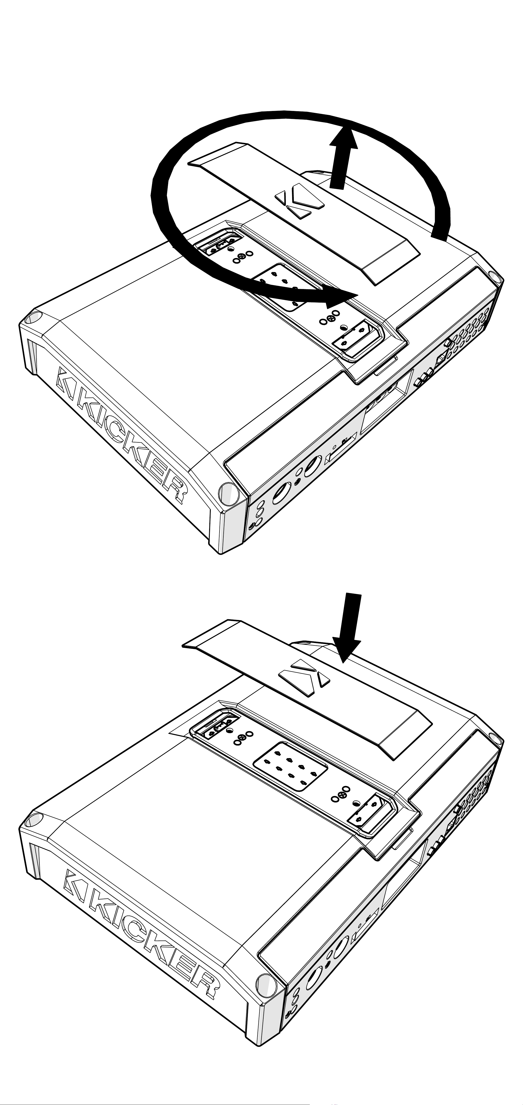
Remove and orient the magnetized KICKER
plate and badge as needed.
53English
Page 54
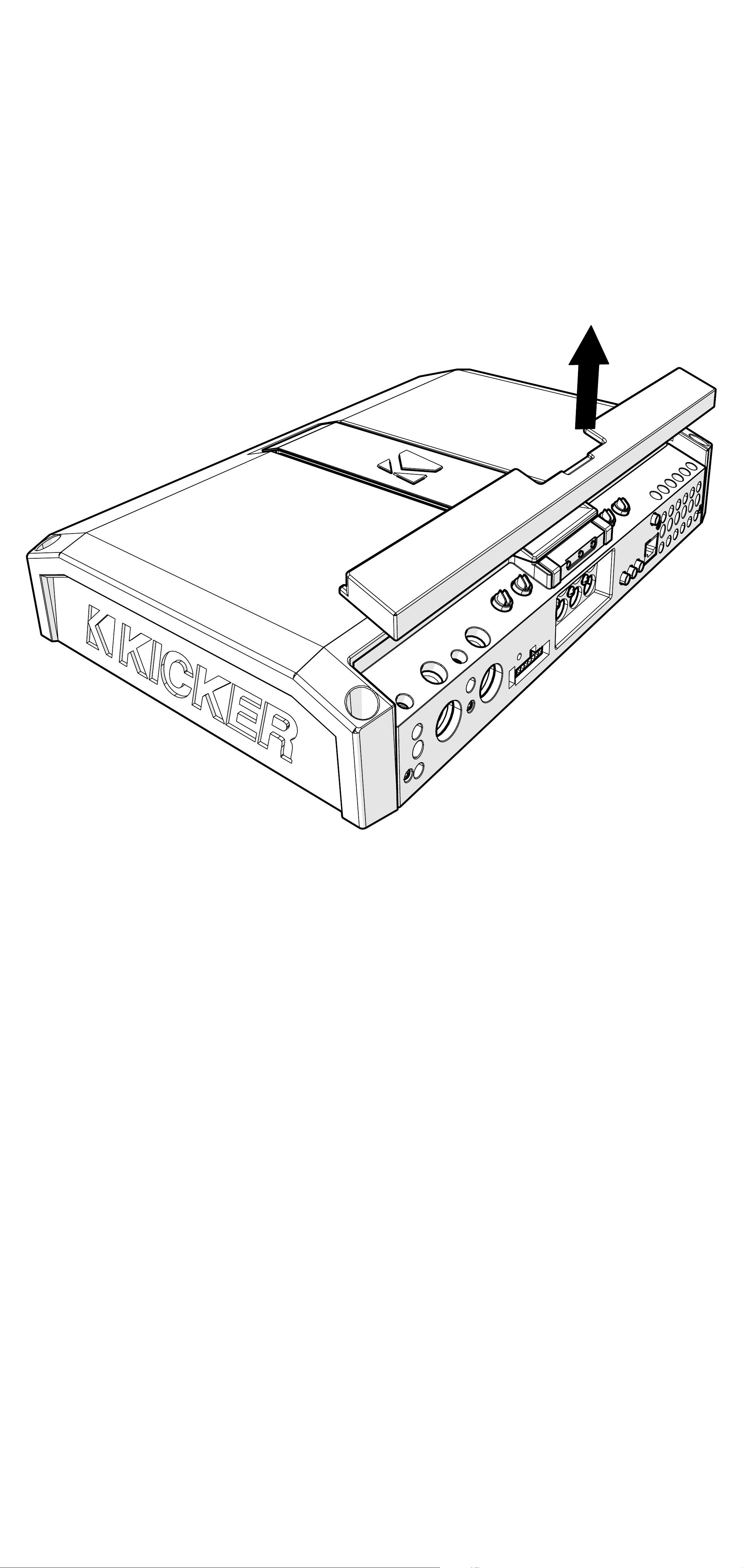
Remove the magnetized top panel cover to
access the LX amplifier’s power distribution
and speaker output terminals, as well as
gain and LED accent lighting settings.
54English
Page 55

Power Wiring
Click Here for Amplifier Install Kits
Model External Fuse (sold separately) Power/Ground Wire KICKER Wiring Kit
LX1200.5 1 x 100 Ampere 1/0 Gauge PKD1
LX1300.7 1 x 150 Ampere 1/0 Gauge PKD1
KICKER will provide a three-year warranty with all
LX-Series Amplifier purchases paired with a qualifying
KICKER Installation Kit*.
This extends the standard warranty by an additional year. Amplifier and Kit
must be purchased from an Authorized KICKER Dealer.
Using poor-quality, under-spec wiring kits will impede LX amplifier performance.
A superior-quality KICKER installation Kit is guaranteed to extend the life of LX amplifiers.
The new extended warranty applies only to KICKER amplifiers and accessories sold to consumers by Authorized
KICKER Dealers in the United States of America or its possessions. It also only applies to the original purchaser of
KICKER amplifiers and accessories. One warranty extension per amplifier is allowed regardless of the number of amplifier
installation kits purchased. This program does not apply to “B”-stock product or factory-refurbished product.
This offer is for a limited time, so see your local Authorized KICKER Dealer soon for details.
*U.S.A. Only | EE.UU. solamente | Nur USA | Les USA Seulement
Disconnect the vehicle’s battery to avoid an
electrical short. A good ground connection
is important. Make the ground wire short,
24” (60cm) or less and, if not conneted
to the battery, connect it to a paint-andcorrosion-free, solid metal area of the
vehicle’s chassis. Adding an additional
ground wire of this same gauge (or larger)
between the battery’s negative post and the
vehicle chassis is recommended. Keep the
audio signal cable away from factory wiring
harnesses and other power wiring. If you
need to cross this wiring, cross it at a 90
degree angle.
55English
Page 56
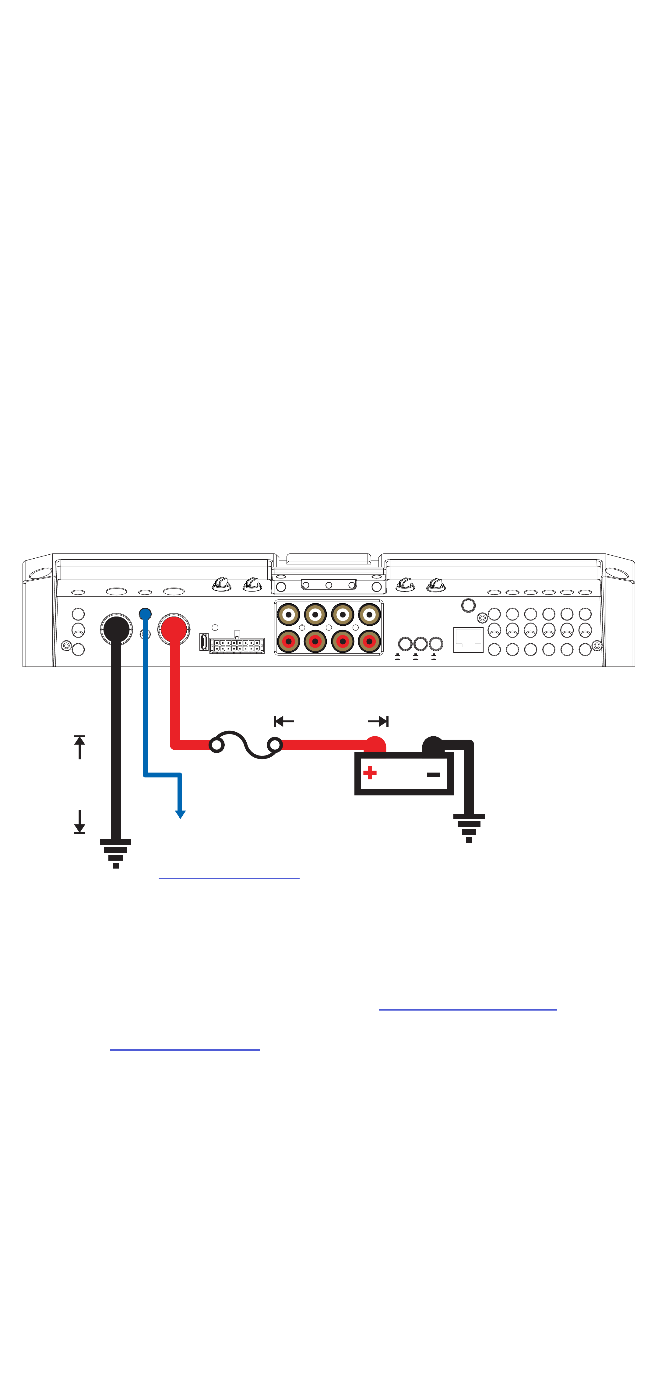
Fuse installation should be as close as
possible to the battery, and no further than
18” (45cm) of the battery, and in-line with
the power cable, which is connected to
your LX Amplifier. Make sure the power wire
is routed so that it will not be damaged,
crimped, or shorted. If you ever need to
remove the amplifier from the vehicle after it
has been installed, the ground wire should
be the last wire disconnected from the
amplifier; just the opposite as when you
installed it.
BRIDGED (L+ AND R-)
+
+
+
+
-
PWR/
PRT
HI-LEVEL
INPUT
AMP1 AMP2 AMP3 SUB
L
AMP2
AMP3
INPUT
AMP2
AMP3
SUB
INPUT
AMP3
SUB
CONTROLLER/
REMOTE BASS
INPUT
R
AMP1
AMP2
+
-
+
-
-
-
-
+
-
≤24”
(60cm)
(45cm)
fuse
remote turn-on
(see page 64)
≤18”
12V
battery
ground
Pro Tip: All that’s left are KS speakers,
and a few cables, and you’ll have an audio
upgrade that will dominate any factory
system! KICKER amplifiers make it easy to
upgrade to solid bass with your existing or
stock source unit. Ask your dealer about
KICKER upgrades.
56English
Page 57
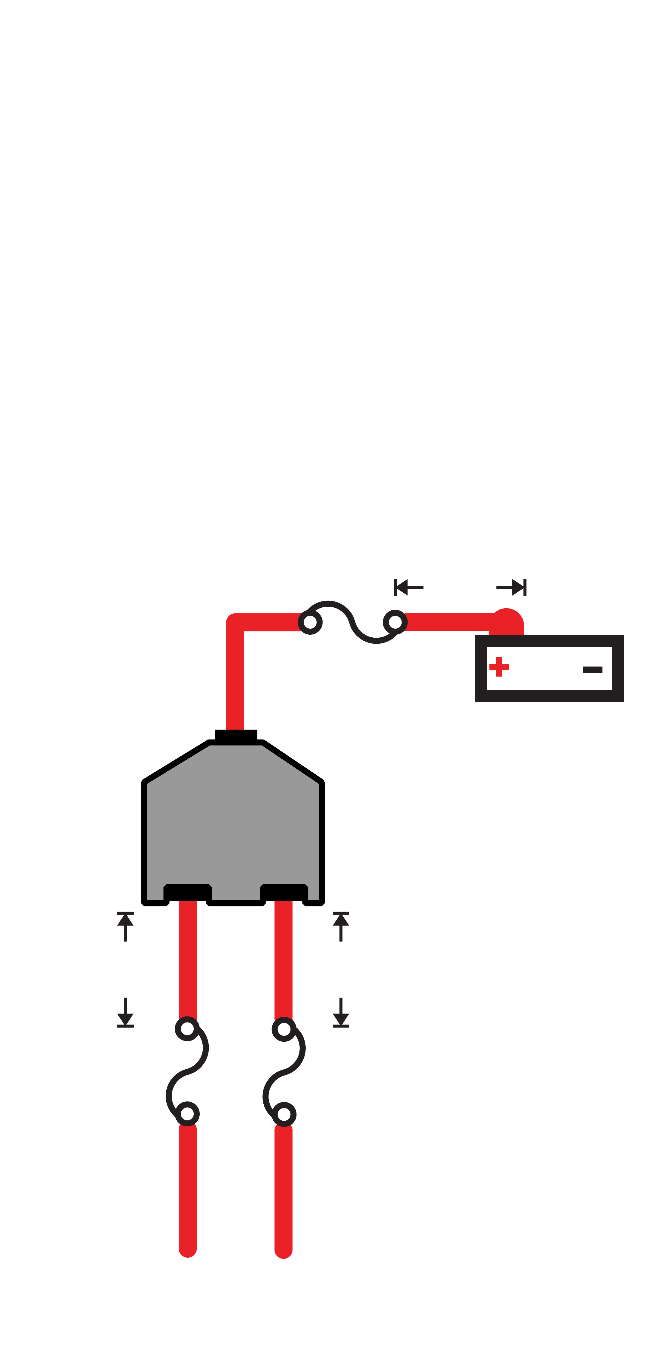
For multiple amplifier installations where
distribution blocks are used, each amplifier
should have its proper-rated fuse, or
breaker, installed between the amplifier and
the distribution block within eighteen inches
of the block, or on the distribution block if it
provides for fusing. The primary power wire
should also be fused between the battery
and distribution block, within eighteen
inches of the battery’s positive terminal, with
a fuse or breaker rated at least to the sum
of the individual amplifier’s fuse values, but
doesn’t exceed the capacity of your wiring.
≤18”
(45cm)
external fuse
power distribution block
12V
battery
≤18”
(45cm)
external fuse
≤18”
(45cm)
external fuse
to amplifiers
57English
Page 58
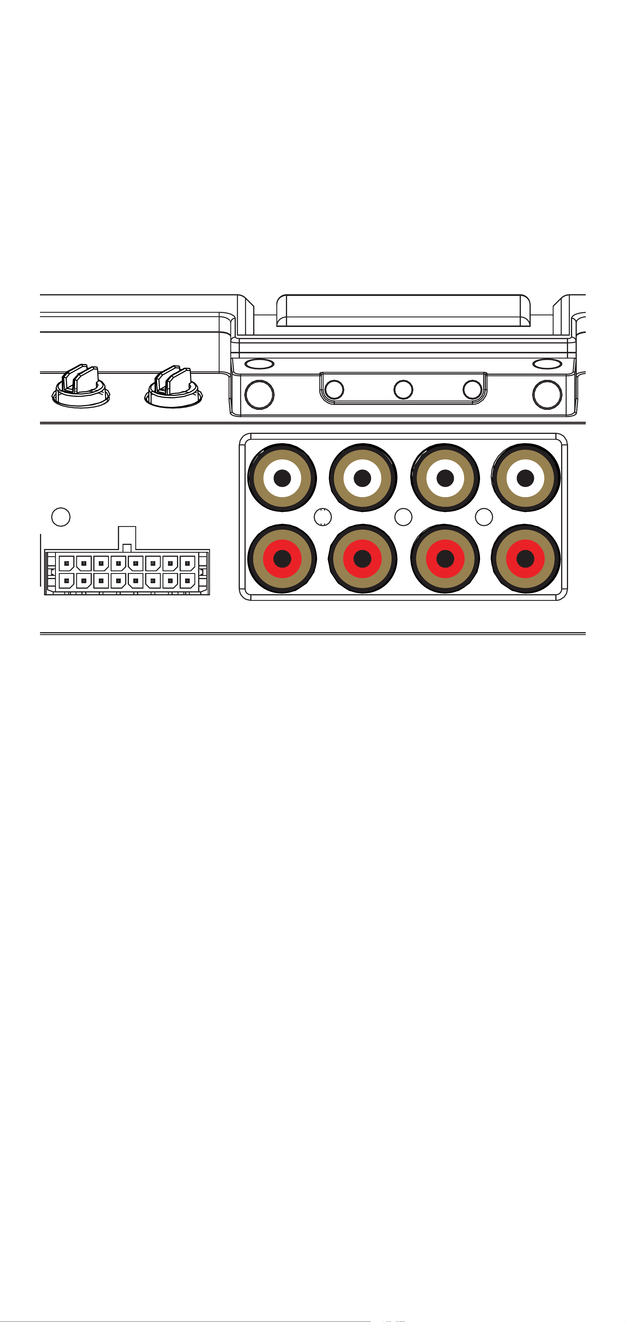
Input Wiring
AMP2
INPUT
AMP3
INPUT
AMP1
AMP2
The LX-series are capable of receiving both
Low-level signals with the RCA inputs and
Hi-level signals with the Hi-Level Input wiring
harness on the front panel of the amplifier.
PWR/
PRT
HI-LEVEL
INPUT
L
R
AMP1 AMP2 AMP3 SUB
The input channel corresponding to the
wiring harness colors are:
LX1200.5
AMP1 Left: White, White/Black
AMP1 Right: Grey, Grey/Black
AMP2 Left: Green, Green/Black
AMP2 Right: Purple, Purple Black
SUB Left: White, White/Black
SUB Right: Grey, Grey/Black
58English
Page 59

LX1300.7
AMP1 Left: White, White/Black
AMP1 Right: Grey, Grey/Black
AMP2 Left: Green, Green/Black
AMP2 Right: Purple, Purple Black
AMP3 Left: White, White/Black
AMP3 Right: Grey, Grey/Black
SUB Left: Green, Green/Black
SUB Right: Purple, Purple Black
59English
Page 60
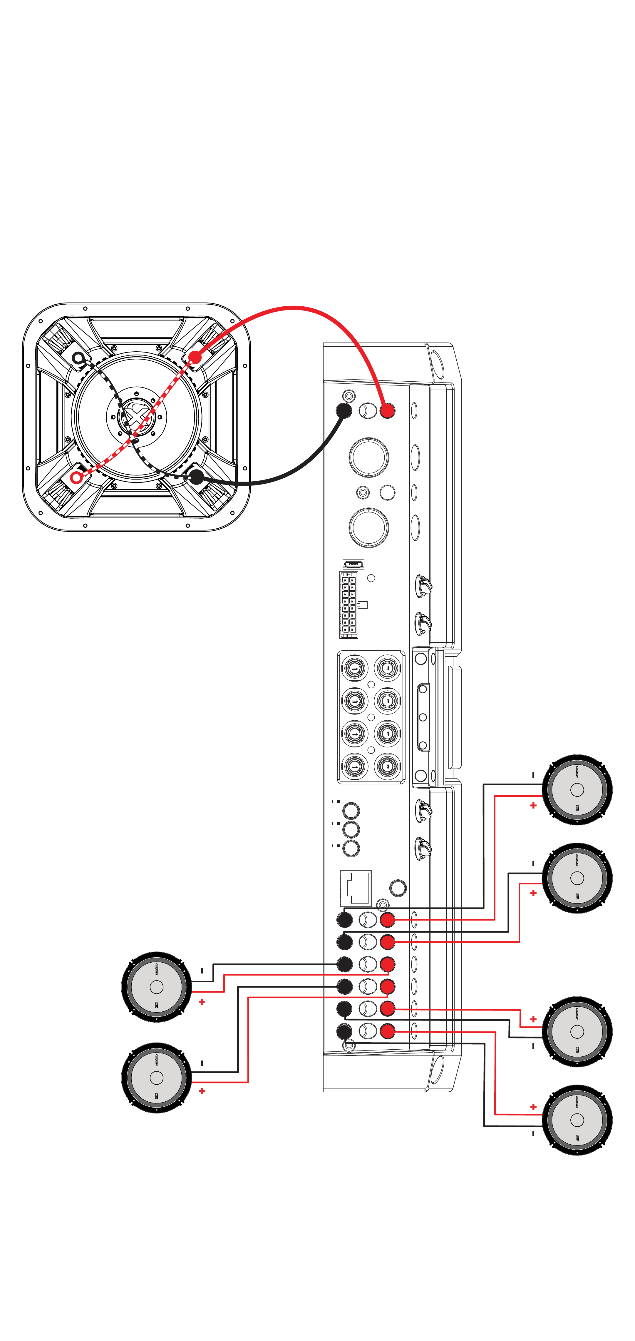
Speaker Wiring
Stereo & Sub Operation
Sub Channel
-
PRT
+
PWR/
HI-LEVEL
INPUT
AMP1 AMP2 AMP3 SUB
AMP1
AMP2
R
AMP1
AMP2
AMP2
AMP3
AMP3
SUB
REMOTE BASS
CONTROLLER/
-
-
INPUT
AMP2
INPUT
AMP3
INPUT
SUB
L
+
BRIDGED (L+ AND R-)
+
-
-
-
-
+
+
+
+
AMP3
60English
Page 61
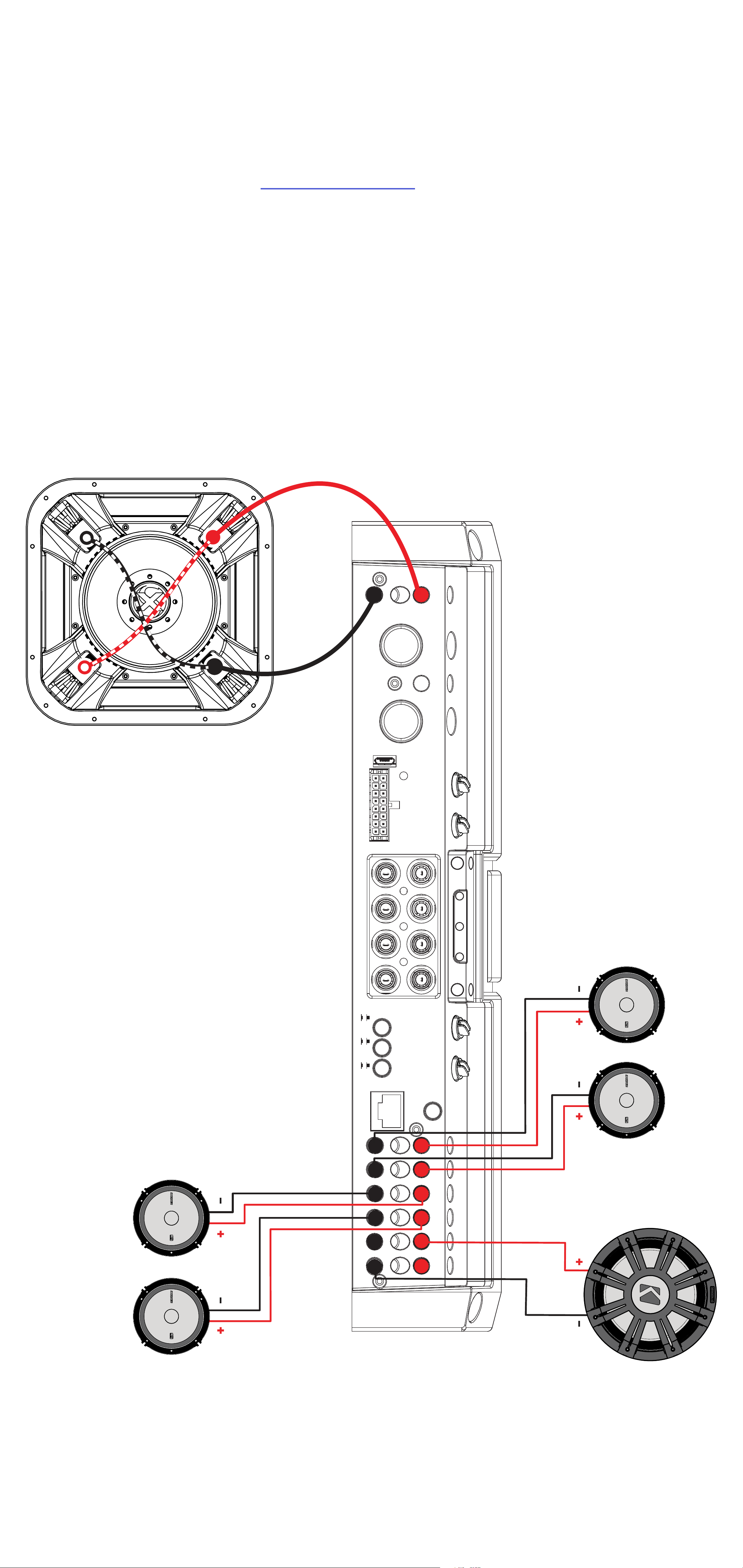
Stereo, Sub & Bridged Operation
All stereo amplifier outputs (AMP1, AMP2 & AMP3) are
capable of bridged mono output. Please refer to the RMS
Power Output in the specifications for bridged output
power relative to impedance. Use the LEFT+ and RIGHT –
terminals of the desired amplifier output to be bridged.
Sub Channel
HI-LEVEL
INPUT
-
PRT
+
PWR/
AMP2
AMP1 AMP2 AMP3 SUB
AMP2
AMP3
SUB
AMP1
AMP2
AMP3
R
INPUT
AMP2
INPUT
AMP3
INPUT
SUB
AMP1
L
REMOTE BASS
CONTROLLER/
-
-
-
-
-
-
+
BRIDGED (L+ AND R-)
+
+
+
+
+
Bridged
AMP3
61English
Page 62
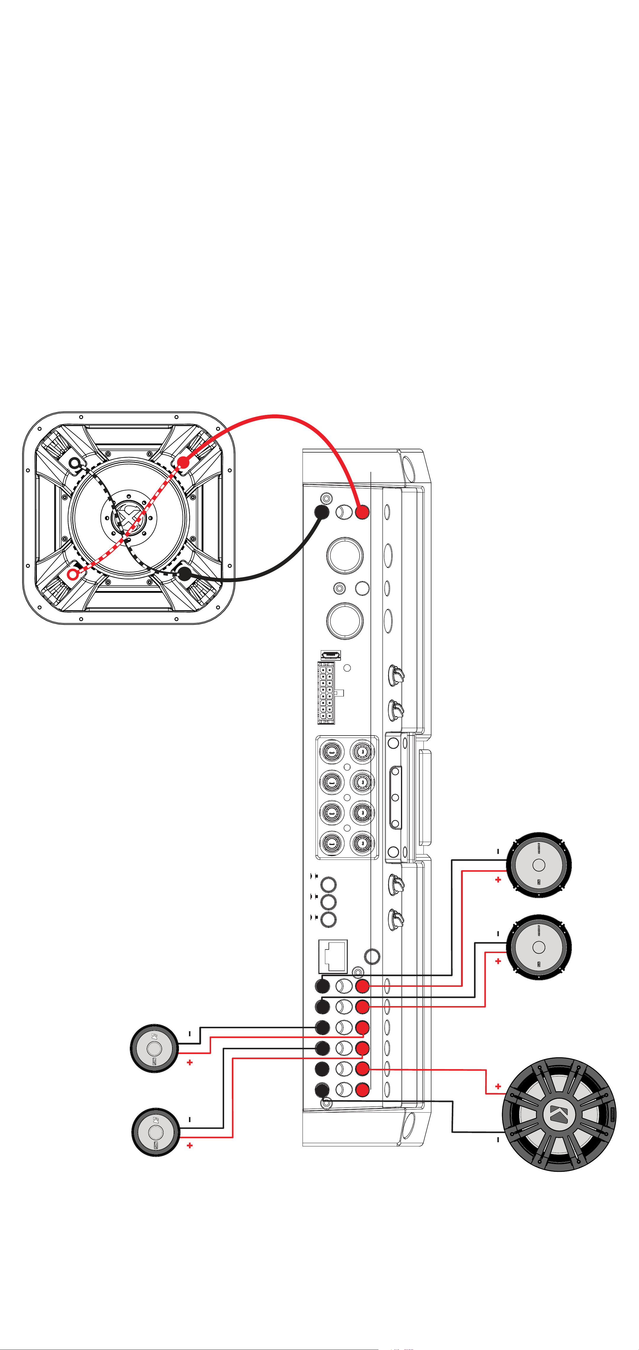
Bi-Amplification with Bridged Subwoofer
Bi-Amplification and tri-amplification dedicate stereo amplifier
channels to specific frequency ranges to increase efficiency
and headroom, greatly improving audio quality. As an
example, you can use one stereo output for tweeters, and
another stereo output for your mids.
Sub Channel
HI-LEVEL
INPUT
-
PRT
+
PWR/
AMP1 AMP2 AMP3 SUB
AMP2
AMP3
SUB
AMP1
AMP2
AMP3
R
INPUT
AMP2
INPUT
AMP3
INPUT
SUB
AMP1
L
AMP2
REMOTE BASS
CONTROLLER/
-
-
-
-
-
-
+
BRIDGED (L+ AND R-)
+
+
+
+
+
Bridged
AMP3
62English
Page 63
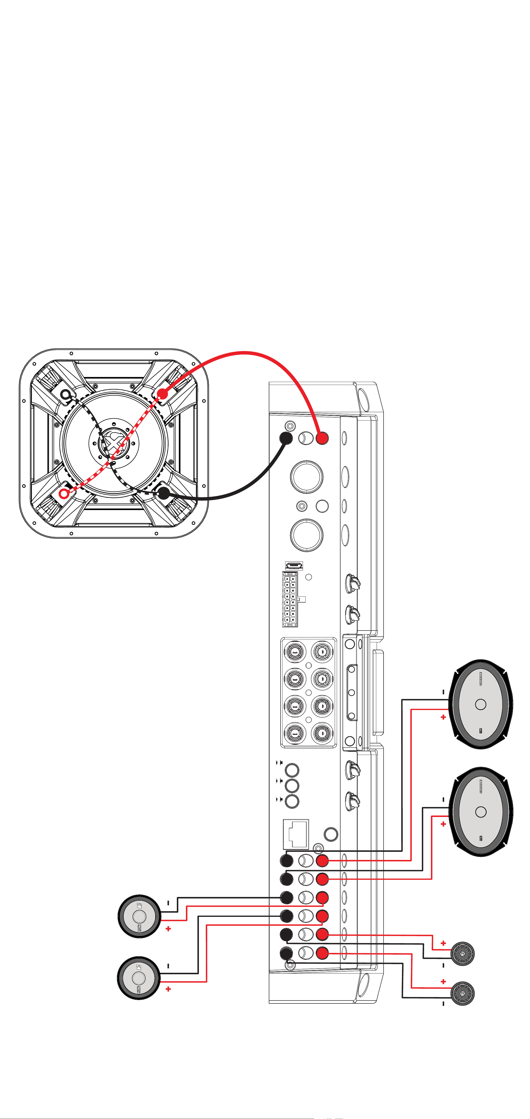
Tri-Amplification (LX1300.7 only)
As an example, the diagram below shows
a tri-amplification wiring configuration using
KICKER KSS693 Component Speakers,
including a 6”x9”, 2-3/4” mid, and 1”
tweeter.
Sub Channel
HI-LEVEL
INPUT
-
PRT
+
PWR/
AMP1
AMP1 AMP2 AMP3 SUB
AMP2
AMP3
AMP1
AMP2
R
INPUT
AMP2
INPUT
AMP3
L
AMP2
AMP3
SUB
REMOTE BASS
CONTROLLER/
-
-
-
-
INPUT
SUB
+
BRIDGED (L+ AND R-)
+
+
+
-
-
+
+
AMP3
63English
Page 64
Operation
DC OFFSET
OFF
ON
L R L R L R
AMP1 AMP2 AMP3
SUB
AMP1
GAIN
GND REM +12V
GAIN
MATCH
+
-
PWR/
PRT
HI-LEVEL
INPUT
AMP2
GAIN
GAIN
MATCH
AMP1 AMP2 AMP3 SUB
AMP3
GAIN
GAIN
MATCH
L
AMP2
INPUT
R
AMP1
AMP2
AMP3
INPUT
AMP2
AMP3
SUB
GAIN
GAIN
MATCH
SUB
INPUT
AMP3
SUB
DC OFFSET
OFF
ON
CONTROLLER/
REMOTE BASS
AMP1 AMP2 AMP3
L R L R L R
BRIDGED (L+ AND R-)
+
+
+
+
-
+
-
-
-
-
+
-
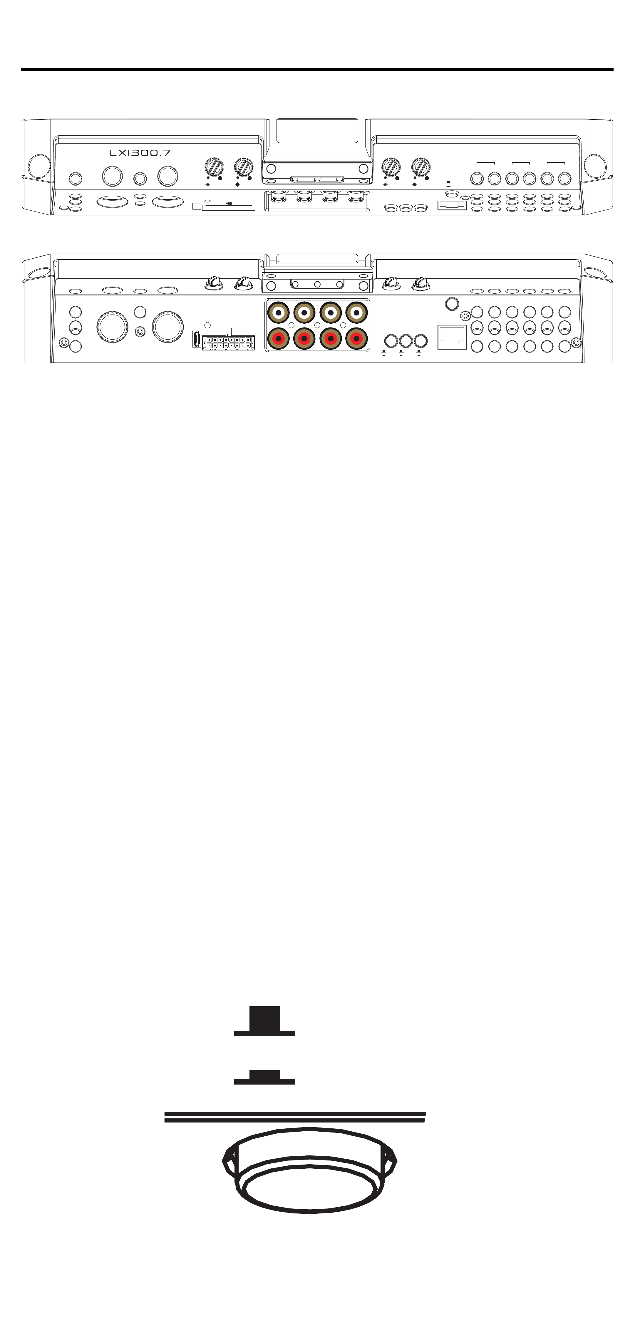
Automatic Turn-On: The LX-series offers
two different automatic turn-on modes;
+12V and DC Offset.
• Remote Turn-On: Run 18 gauge wire from the Remote
Turn-On Lead on your source unit to the REM terminal on
the LX amplifier’s end panel.
• DC Offset Turn-On: The DC Offset mode uses the HiLevel input harness to detect >2.5V DC from the Hi-Level
speaker output of the source unit when it has been turned
on. To use DC offset mode, the DC OFF/ON push button
must be in the ON or IN position. When using DC Offset
mode, the REM terminal becomes a switched +12V
output (100mA) to turn other amplifiers and devices on.
64English
Page 65
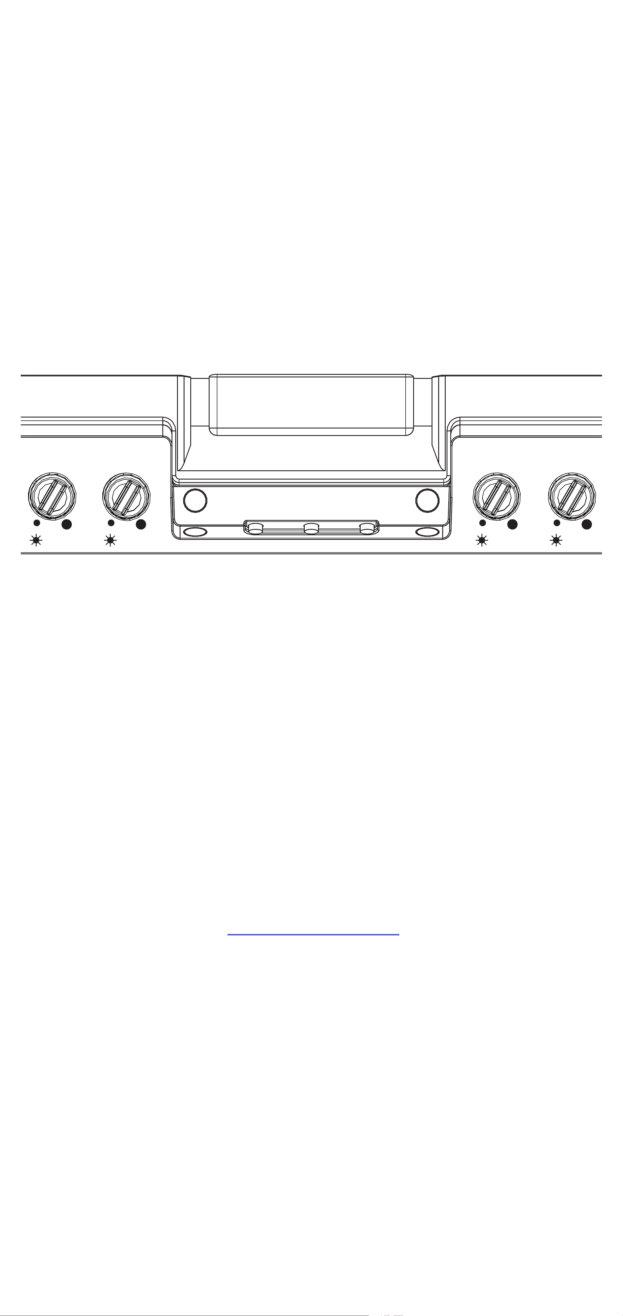
INPUT GAIN: The input gain control is
DC OFFSET
not a volume control. It matches the output
of the source unit to the input level of
the amplifier. Maximum power out of the
amplifier is possible with the gain in the
lowest position. Incorrectly setting the gain
can result in distorted output or damage to,
and premature failure of, your speakers.
AMP1
GAIN
GAIN
MATCH
AMP2
GAIN
GAIN
MATCH
AMP3
GAIN
GAIN
MATCH
SUB
GAIN
GAIN
MATCH
GAIN MATCHING: In any audio system,
the goal is to reach maximum input and
output levels without distortion or clipping.
The engineers at KICKER have taken the
guesswork, and hassle, out of matching
the output voltage of your source unit to the
amplifier with the Gain Matching feature. To
begin, you’ll need to download the KICKER
test tones from KICKER.com.
These test tones are sine waves meant to
provide a consistent signal for the amplifier
to reference. The different recording levels
are designed to give you the perfect gain
match for your application.
65English
Page 66

0dBFS: Designed for audiophile applications
to give you distortion free audio output with the
most dynamic range.
-5dBFS: Designed for normal/daily
applications, there will be less dynamic range
but higher potential audio output levels. With this
set up you can get some occasional clipping
from the amplifier.
-10dBFS: Designed only for Subwoofer
applications, there will be less dynamic range
but higher potential audio output levels. With
this set up you can get some clipping from the
amplifier.
Afterwards, use the following procedure to
accurately Gain Match your amplifier(s):
1. Disconnect the speakers from the
amplifier.
2. Set all EQ and crossover settings to flat
on your source unit.
3. Play the downloadable file from
KICKER.com
4. Turn the source unit up to the maximum
unclipped volume level. If you cannot
accurately determine this, ¾ volume is a
good starting point.
5. Increase the gain of the amplifier until
the Gain LED turns on.
6. Decrease the gain of the amplifier until
the Gain LED turns off.
66English
Page 67

To use the preferred method of setting the
input gain using a voltmeter or oscilloscope,
begin by turning off the amplifier and
disconnecting all speakers from it. Turn the
gain knob completely off (counterclockwise)
and all crossovers off, or to their least
effective setting. If a remote bass accessory
is connected to the amplifier, turn it
completely on (clockwise). Ensure all EQ
and DSP settings on the source unit such
as bass, treble, fader, seating position etc
are set to linear, flat, center, or off. Turn on
the amplifier. With an oscilloscope, probe
the signal coming from the source unit and
play a 0dB sine wave through your source
unit and increase the volume until you see
the waveform clip slightly. Turn the head unit
down one notch as this is the maximum
unclipped volume level of your source unit.
Sine wave tracks can be downloaded for
free from KICKER.com under the “Support”
tab. Use the 50Hz sine wave to set the gain
for a subwoofer and the 1kHz sine wave for
full-range speakers. Set your voltmeter or
oscilloscope to measure AC voltage. Place
the voltmeter’s probes on the amplifier’s
speaker output terminals. With the sine
wave playing, slowly turn the gain knob
clockwise and watch the AC voltage on the
voltmeter increase.
67English
Page 68

When the desired voltage is shown
(reference power chart at KICKER.com), or
you start to see the waveform square off
stop increasing the gain, turn the amplifier
off, reconnect all speakers and set the
crossovers to your desired setting. Your
gain is now set for maximum unclipped
power from the amplifier. If you increase
amplitude using settings on the source unit
or the bass boost on the amplifier it will
introduce distortion and you will need to
redo these steps.
LED Accent Lighting: Remove the top
panel cover to access the LED Accent
Lighting Controls. These also control the
LXRC lighting.
Change LED
Color
Change LED
Brightness
Press the Change LED Color button to
cycle through the available colors. Press
the Change LED Brightness to change the
intensity of the light, or to turn it off.
Available Colors:
Red Magenta Violet
Blue Light Blue Cyan
Dark Green Green Yellow
Orange White
68English
Page 69

Factory Reset: Remove the top panel
CONTROLLER/
REMOTE BASS
cover to access the Factory Reset button.
To restore factory settings, press and hold
the Factory Reset button for 10 seconds.
Turn the amplifier off and back on by cycling
the ignition.
Factory Reset - Press & Hold for 10 seconds
WARNING: Factory reset will reset all
settings that are controlled by LXCC to
factory (including crossover)
AMP/SUB INPUT Buttons: Turn the
AMP INPUT Button(s) ON if you are running
more than a single pair of RCA inputs to
the amplifier. Turn the AMP INPUT button(s)
OFF if you want to drive those channels
from a single input. For example, if you are
using the AMP1, AMP2, AMP3, and SUB
RCA inputs, switch the AMP1/AMP2 INPUT,
AMP2/AMP3 INPUT, and AMP3/SUB
INPUT buttons to ON.
AMP2
AMP3
SUB
INPUT
AMP1
INPUT
AMP2
INPUT
AMP3
AMP2
AMP3
SUB
69English
Page 70
LXCC
GND
REM
+12V
GND
REM
+12V
FADERFADER
OFFONOFF
ON
BRIDGED (L+ AND R-)
HI-LEVEL
INPUT
PWR/
PRT
R
L
AMP1
AMP2
OUTPUT
HI-LEVEL
INPUT
PWR/
PRT
R
L
AMP1
AMP2
OUTPUT
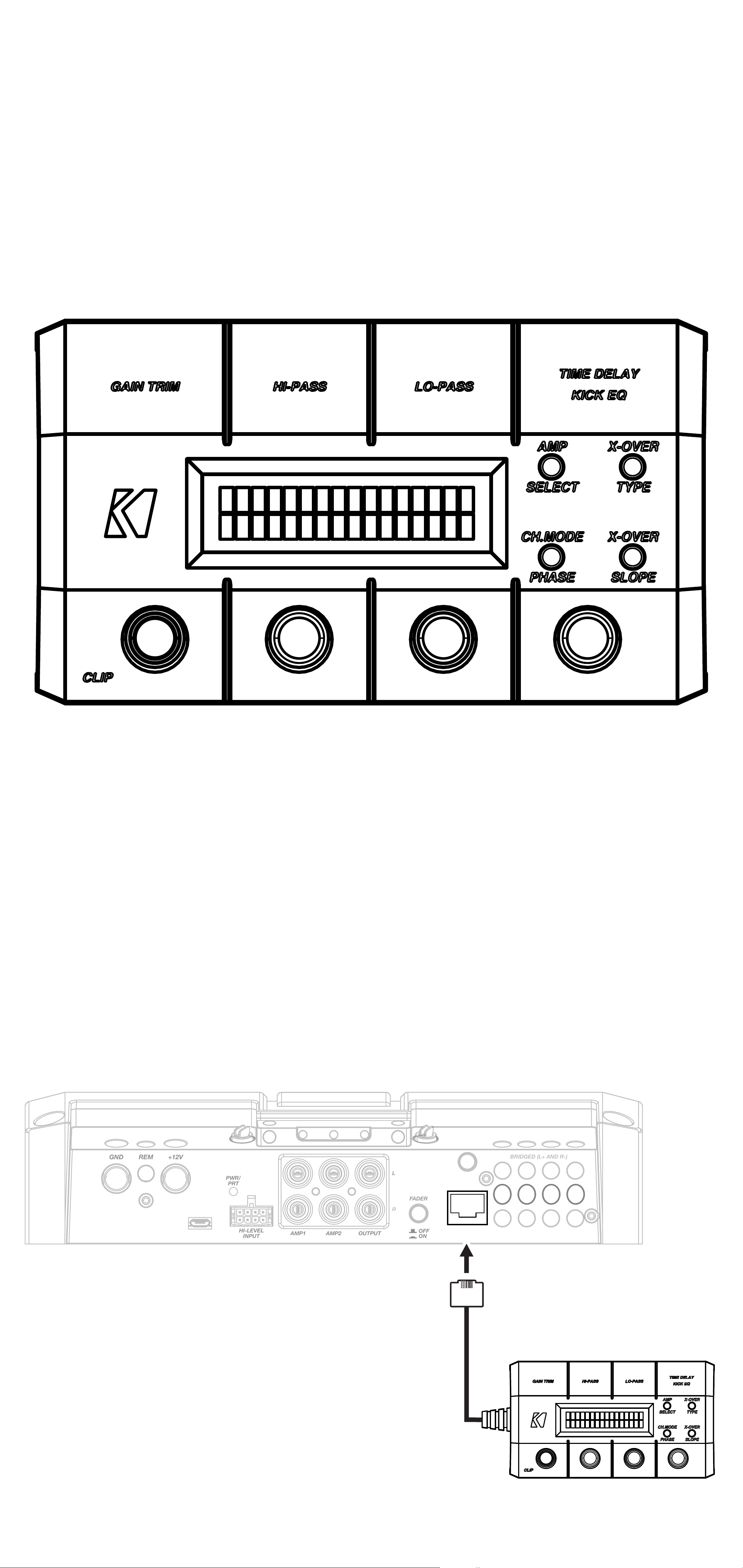
The LXCC is a Control Center that grants
access to the expanded DSP functions of
the LX amplifier, allowing you to fine-tune
your LX with ease.
Once your LX amplifier has been installed,
begin by connecting the RJ-45 cable of
the LXCC to the Controller/Remote Bass
input of the LX amplifier. The center display
will immediately show real-time amplifier
information, including amp model, amp
temperature, and supplied voltage.
CONTROLLER
70English
Page 71

GAIN TRIM: Push the Gain Trim knob to
open Gain Trim settings. Push the knob
again or the Amp Select button to select the
amplifier channel being modified. You can
cut by -9dB or boost by +3dB per amplified
section (AMP1, AMP2, AMP3, & SUB).
This allows you to make minor adjustments
to levels, helping to match outputs, such
as cutting your tweeter channels, while
boosting the mids.
CLIP: The CLIP indicator will illuminate
when the amplifier output is above the
clipping threshold. This only applies to the
amplifier channel currently selected (AMP
SELECT). If you change your Gain, Bass
Boost or SHOCwave setting, you may
notice the CLIP LED become active. This
means your new DSP settings have caused
an output to clip and you should reduce the
gain or compensate in some other way.
HI-PASS | LO-PASS: Push the HI-PASS
or LO-PASS knob to open the crossover
settings. Push the AMP SELECT button to
select the amplifier channel being modified.
The display will show the amplifier channel
being modified, the current crossover (FR:
Full-Range, HP: Hi-Pass, LP: Lo-Pass, BP:
Band-Pass), and the crossover point.
71English
Page 72

Use the knobs to set your crossover points,
between 20Hz–5kHz HP/BP and 40Hz–
5kHz LP for full-range channels, or 10Hz–
160Hz for a subwoofer channel. Using a
Hi-Pass filter on a subwoofer channel will
engage the subsonic filter.
X-OVER TYPE: Select the amplifier
channel for which you’d like to change
the crossover type. Press the X-OVER
TYPE button to choose Linkwitz-Riley or
Butterworth. Each amplifier channel may
have its own crossover type.
X-OVER SLOPE: Select the amplifier
channel for which you’d like to change the
crossover slope. Press the X-OVER SLOPE
button to choose between the available
slope options. Each amplifier channel may
have its own crossover slope. The available
slopes are:
Linkwitz-Riley: 24dB, 12dB
Butterworth: 24dB, 18dB, 12dB
TIME DELAY: The Time Delay will delay
the left channel of the stereo outputs up
to 10ms, in increments of 0.1ms. This will
allow you to set the center stage according
to your preferences and listening position.
72English
Page 73

KICK EQ Parametric Bass Boost:
When the subwoofer channel is selected,
the TIME DELAY knob will instead become
a KICK EQ Parametric Bass Boost for
the subwoofer channel. This boost is
independent of the GAIN TRIM setting,
and may be set from 0dB–6dB. Press the
knob to set the amount of boost. Press
it a second time to choose the center
frequency to which the boost is applied.
Press it a third time to set the bandwidth
(Q) of the center frequency, from 1–5 in
increments of 0.1.
Channel Mode | Phase: Use the Channel
Mode button with a full-range stereo
amplifier channel to change the selected
channel output to stereo, L+R Summed, or
L-R Summed.
Use the PHASE setting with a subwoofer
channel to select the phasing; 0°, or 180°.
If you are experiencing an absence of bass
in the audio, the bass frequency may be
out of phase with the rest of the system.
Reversing positive/negative polarity, or
changing subwoofer location may also
resolve these types of issues.
73English
Page 74
LXRC Installation
HI-LEVEL
INPUT
AMP1
AMP2
SUB
OFFONAMP2
SUB
FADER
SUB
INPUT
PWR/
PRT
L
R
+-+-+-+
-
BRIDGED (L+ AND R-)
+
-
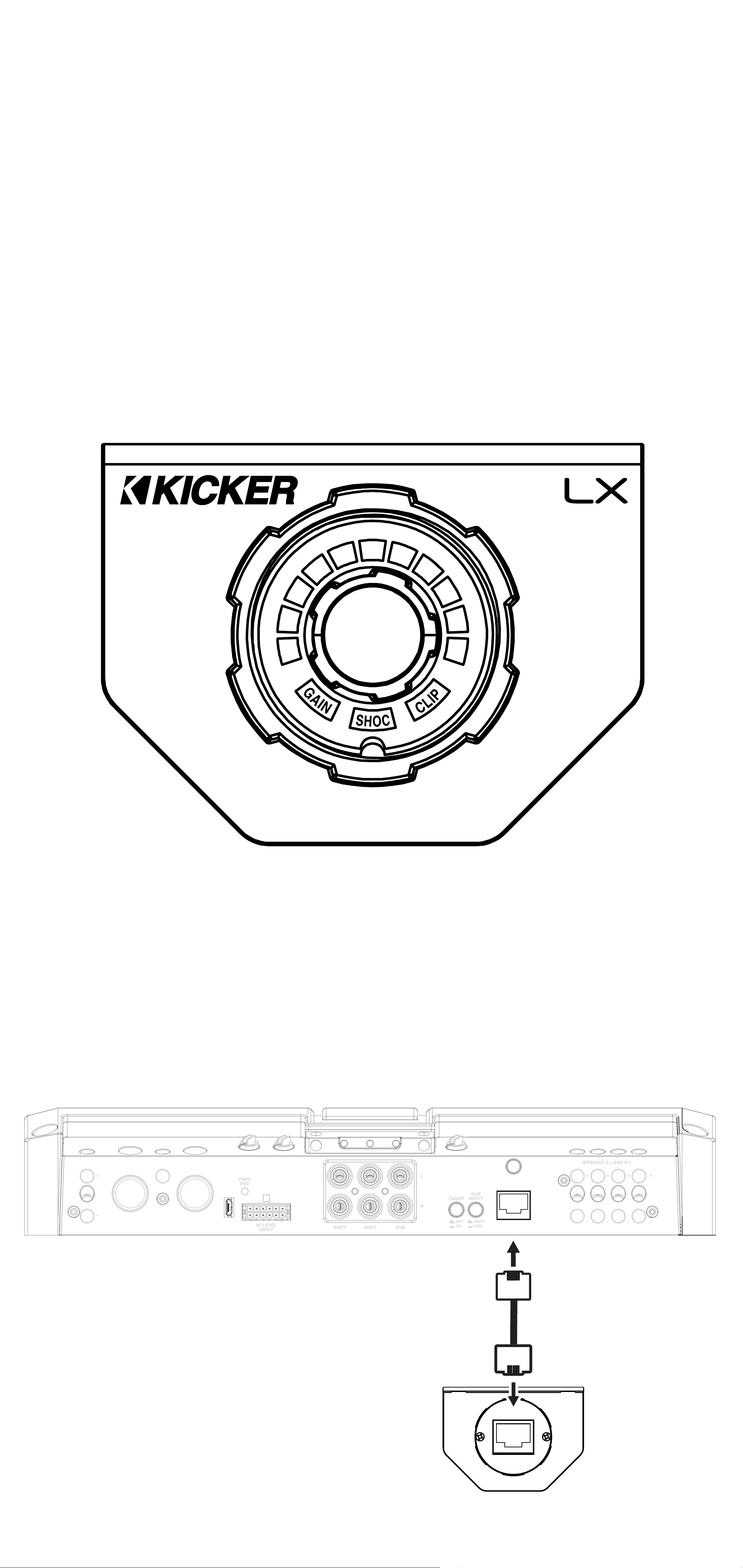
The LXRC is a multi-function remote bass
knob that further expands the DSP features
of the LX amplifier, with access to LED
lighting changes, real-time battery input
voltage monitoring, clip output indication,
and KICKER’s proprietary SHOCwave 2.0
(Sub-Harmonic Octave Creation) algorithm.
Disconnect the supplied RJ-45 cable used
to fine-tune with the LXCC, then connect
from the back of the LXRC to the Remote
Bass jack of the LX amplifier.
CONTROLLER/
REMOTE BASS
74English
Page 75
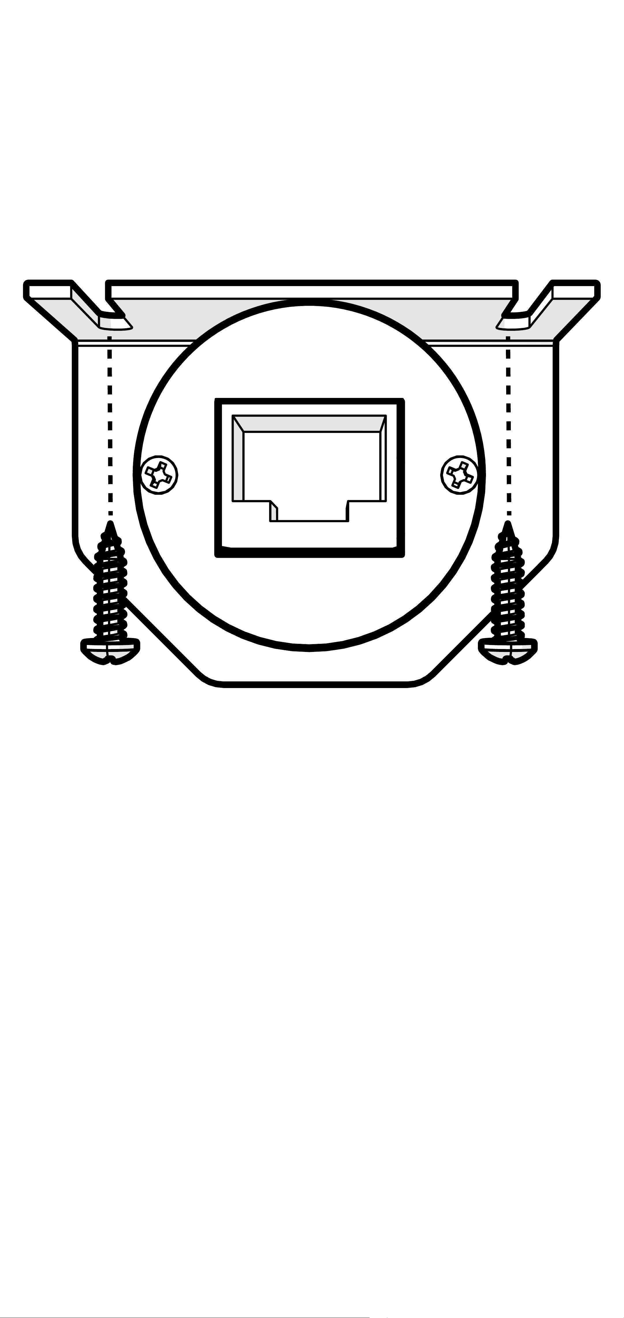
Surface Mounting: To surface mount the
LXRC, place the LXRC against a surface
and secure the mounting bracket using the
supplied screws.
75English
Page 76
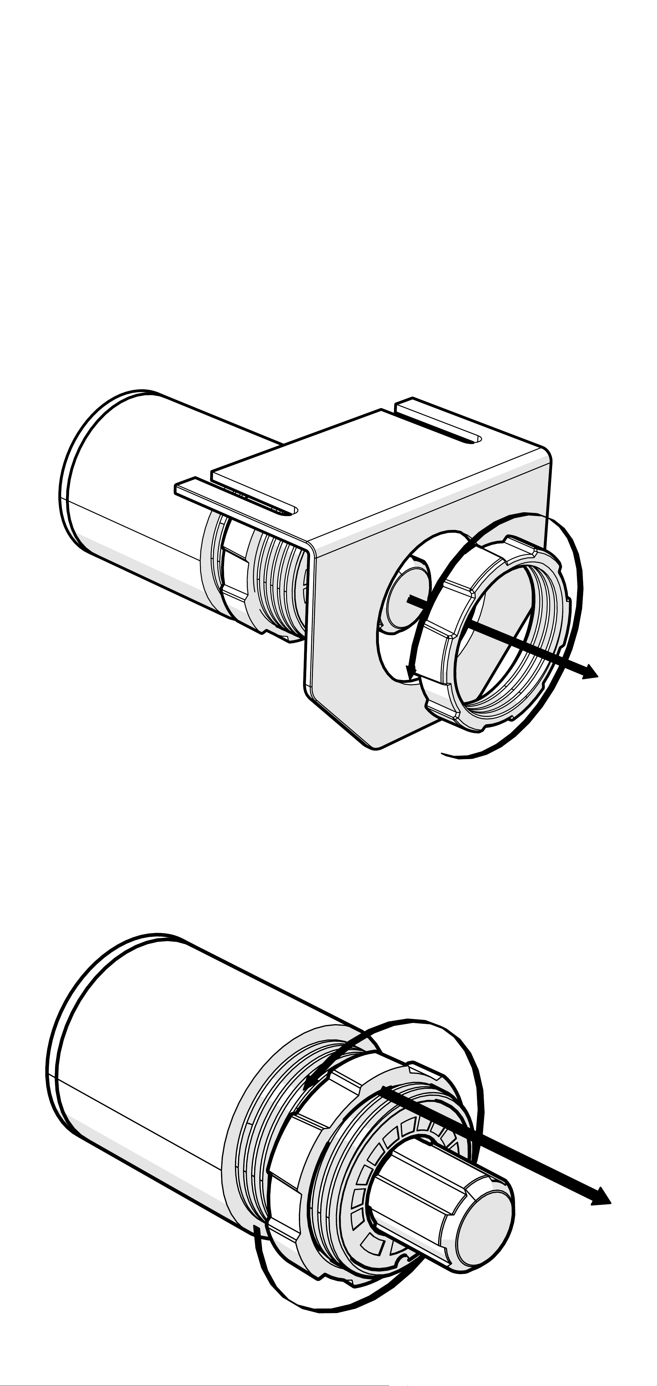
Flush Mounting: To flush mount the LXRC
behind a mounting surface, begin by cutting
a 1-inch diameter hole in the mounting
surface, being careful not to drill through
existing wiring or mechanisms.
Remove the LXRC front mounting nut and
mounting bracket.
Adjust the rear mounting nut forward to set
the protrusion of the LXRC knob.
76English
Page 77
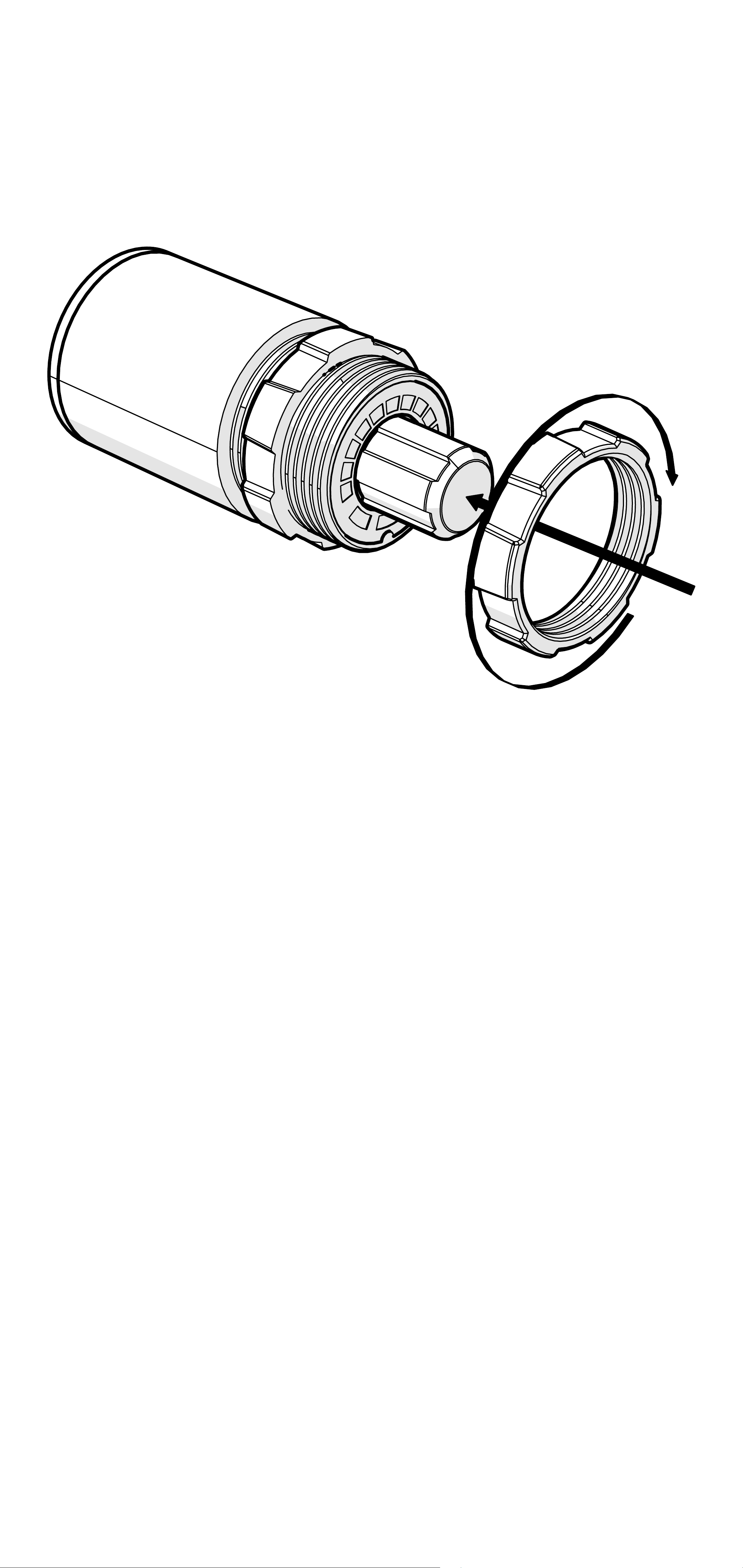
Place the LXRC through the mounting
hole, then reattach the front mounting nut
to secure the remote against the mounting
surface.
Connect the LXRC to the Remote Bass jack
of the LX amplifier.
77English
Page 78

LXRC Operation
The LXRC serves as both a rotary knob for
precise adjustments and as a multi-function
push-button to change modes, with an
illuminated LED ring to display the current
setting. You may cycle through most modes
by pressing and holding the button for <3
seconds (short-press). Once adjustments
have been made, wait for the LXRC to save
the settings and return to the default Voltage
Indication mode.
Voltage: The LXRC will default to showing
the input voltage, with the remote knob LED
ring serving as a VU meter for 11V–16V. To
enter Input Voltage Indication mode, perform
a short-press until the menu cycles, perform
no interaction for 5 seconds.
12.5
12
11.5
<11
13
13.5 14
14.5
15
15.5
16
16.5
78English
Page 79

Gain (Remote Level): The LXRC gain
control is a gain attenuator from -26dB to
0dB. This will allow you to conveniently
adjust the gain of the subwoofer channel
on the fly, with the maximum being the
gain setting you’ve selected on the LX
amplifier top panel. To enter Remote Level
mode, turn the knob while in Voltage mode,
or short-press the knob until the menu
reaches Gain.
™
SHOCwave
2.0: The SHOCwave (Sub
Harmonic Octave Creation) will restore
low frequencies that are weaker in older
recordings or lost in data compression. The
SUBWOOFER channel must be operating
with a full-range signal for this effect to work
properly. Short-Press & hold the knob until
SHOC is illuminated, then adjust the knob
to a level that is satisfactory.
Brightness: Enter the Brightness
adjustment mode by pressing and holding
the LXRC button for >3 seconds (longpress). Rotate the knob to adjust the
brightness to a satisfactory level, then
perform no action for 5 seconds and the
LXRC will return to default voltage mode.
While in voltage mode, if you double-press
the remote button the LXRC LED array will
turn on/off.
79English
Page 80

Clip: The CLIP display serves as a global
clip indicator to show when a clipped output
signal is detected. If you change your Gain
or SHOCwave setting, you may notice the
CLIP LED become active. This means your
new DSP settings have caused an output
to clip and you should reduce the gain or
compensate in some other way.
80English
Page 81

Troubleshooting
If your amplifier does not appear to be working, check the obvious things first such as blown
fuses, poor or incorrect wiring connections, incorrect setting of crossover switch and gain
controls, etc. There are Power (PWR) & Protection (PRT) LEDs on the side panel of your
KICKER LX series amplifier. Depending on the state of the amplifier and the vehicle’s charging
system, the LEDs will glow either green or red. When the green LED is lit, this indicates the
amplifier is turned on and no trouble exists.
Green LED off, no output? With a Volt Ohm Meter (VOM) check the following:
power terminal (should read +12V to +16V)
+16V)
conductivity.
Green LED on, no output? Check the following:
outputs with a “known” good speaker.
unit.
measure “AC” voltage. Use a 50Hz test tone.
Check for reversed power and ground connections
Substitute source unit with a “known” good source
Check for a signal in the RCA cable feeding the amplifier with the VOM meter set to
Remote turn-on terminal (should read +12V to
Ground terminal, for proper
RCA connections
Test speaker
+12 volt
Red (PRT) LED flickering with loud music? The red (PRT) LED indicates low battery
voltage. Check all the connections in your vehicle’s charging system. It may be necessary to
replace or charge your vehicle’s battery or replace your vehicle’s alternator.
Red (PRT) LED on, no output?
Test for proper impedance at the speaker terminals with a VOM meter set to “DC Resistance”
(see the diagrams in this manual for minimum recommended impedance and multiple
speaker wiring suggestions). Also check for adequate airflow around the amplifier.
shuts down only while vehicle is running = voltage protection circuitry is engaged. Voltage
Amplifier is very hot = thermal protection is engaged.
Amplifier
to the amplifier is not within the 6–16 volt operating range. Have the vehicle’s charging
and electrical system inspected.
circuit protection is engaged. Check for speaker wires shorted to each other or to the
vehicle chassis. Check for damaged speakers or speaker(s) operating below the minimum
recommended impedance.
No or low output?
RCA (or speaker input) and speaker output connections.
source unit, to include the volume level of any connected phones or MP3 players.
Check the balance and fader controls on source unit.
Amplifier will only play at low volume levels = short
Check the
Check the volume level on your
Alternator noise-whining sound with engine’s RPM?
(or speaker input) cable
source unit for proper grounding
set too high.
CAUTION: When jump starting the vehicle, be sure that connections made with jumper
cables are correct. Improper connections can result in blown amplifier fuses as well as the
failure of other critical systems in the vehicle.
Check the routing of RCA (or speaker input) cable
Check the gain settings and turn them down if they are
Check for damaged RCA
Check the
If you have more questions about the installation or operation of your new KICKER product,
see the Authorized KICKER Dealer where you made your purchase. For more advice on
installation, click on the SUPPORT tab on the KICKER homepage, www.KICKER.com.
Choose the TECHNICAL SUPPORT tab, choose the subject you are interested in, and then
download or view the corresponding information. Please E-mail [email protected] or call
Technical Services (405) 624-8583 for unanswered or specific questions.
81English
Page 82

Warranty
When purchased from an Authorized KICKER Dealer, KICKER
warrants this product to be free from defects in material and
workmanship under normal use for a period of TWO (2) YEARS from
date of original purchase with receipt. If this product is identified as
“Refurbished” or “B Goods”, the warranty is limited to a period of
THREE (3) MONTHS from the date of original purchase. In all cases
you must have the original receipt. Should service be necessary
under this warranty for any reason due to manufacturing defect
or malfunction during the warranty period, KICKER will repair or
replace (at its discretion) the defective merchandise with equivalent
merchandise. Warranty replacements may have cosmetic scratches
and blemishes. Discontinued products may be replaced with more
current equivalent products. This warranty is valid only for the original
purchaser and is not extended to owners of the product subsequent
to the original purchaser. Any applicable implied warranties are limited
in duration to a period of the express warranty as provided herein
beginning with the date of the original purchase at retail, and no
warranties, whether express or implied, shall apply to this product
thereafter. Some states do not allow limitations on implied warranties;
therefore, these exclusions may not apply to you. This warranty gives
you specific legal rights; however you may have other rights that vary
from state to state.
WHAT TO DO IF YOU NEED WARRANTY OR SERVICE:
Defective merchandise should be returned to your local Authorized
Stillwater Designs (KICKER) Dealer for warranty service. Assistance
in locating an Authorized Dealer can be found at www.KICKER.com
or by contacting Stillwater Designs directly. You can confirm that
a dealer is authorized by asking to see a current authorized dealer
window decal.
If it becomes necessary for you to return defective merchandise
directly to Stillwater Designs (KICKER), call the KICKER Customer
Service Department at (405) 624-8510 for a Return Merchandise
Authorization (RMA) number. Package only the defective items in a
package that will prevent shipping damage, and return to:
Stillwater Designs
3100 North Husband St
Stillwater, OK 74075
82English
Page 83

The RMA number must be clearly marked on the outside of the
package. Please return only defective components. The return
of functioning items increases your return freight charges. Nondefective items will be returned freight collect to you. For example,
if a subwoofer is defective, only return the defective subwoofer, not
the entire enclosure. Include a copy of the original receipt with the
purchase date clearly visible, and a “proof-of-purchase” statement
listing the Customer’s name, Dealer’s name and invoice number, and
product purchased. Warranty expiration on items without proof-ofpurchase will be determined from the type of sale and manufacturing
date code. Freight must be prepaid; items sent freight-collect, or
COD, will be refused.
WHAT IS NOT COVERED?
This warranty is valid only if the product is used for the purpose for
which it was designed. It does not cover:
o Damage due to improper installation
o Subsequent damage to other components
o Damage caused by excessive heat, chemical cleaners, and/or UV
radiation
o Damage through negligence, misuse, accident or abuse. Repeated
returns for the same damage may be considered abuse
o Any cost or expense related to the removal or reinstallation of
product
o Speakers damaged due to amplifier clipping or distortion
o Items previously repaired or modified by any unauthorized repair
facility
o Return shipping on non-defective items
o Products with tampered or missing barcode labels
o Products with tampered or missing serial numbers
o Products returned without a Return Merchandise Authorization
(RMA) number
o Products purchased from an UNAUTHORIZED dealer
o Freight Damage
o The cost of shipping product to KICKER
o Service performed by anyone other than KICKER
HOW LONG WILL IT TAKE?
KICKER strives to maintain a goal of one week turnaround for
all electronics (amplifiers, crossovers, equalizers, etc.) returns.
Delays may be incurred if lack of replacement inventory or parts is
encountered. Failure to follow these steps may void your warranty.
Any questions can be directed to the KICKER Customer Service
Department at (405) 624-8510. Contact your International KICKER
dealer or distributor concerning specific procedures for your country’s
warranty policies.
83English
Page 84

Contenido
Resumen .....................86
Garantía | Garantie ......323
LX Mono
Especificaciones ................. 87
Instalación ....................89
Montaje ............................... 89
Cableado de alimentación.... 92
Cableado de entrada ........... 95
Cableado de subwoofer ...... 96
Funcionamiento ............97
Instalación de LXRC .......... 104
Funcionamiento del LXRC .. 108
Solución de problemas 111
LX Stereo
Especificaciones ............... 112
Instalación ..................113
Montaje ............................. 113
Cableado de alimentación.. 116
Cableado de entrada ......... 119
84Español
Page 85

Cableado de los parlantes . 120
Funcionamiento ..........123
LXCC ................................ 129
Solución de problemas 132
LX Multi-Channel
Especificaciones ............... 133
Instalación ..................134
Montaje ............................. 134
Cableado de alimentación.. 137
Cableado de entrada ......... 140
Cableado de los parlantes . 142
Funcionamiento ..........146
LXCC ................................ 152
Instalación de LXRC .......... 156
Funcionamiento del LXRC .. 160
Solución de problemas 163
85Español
Page 86

Resumen
ADVERTENCIA DE SEGURIDAD IMPORTANTE
EL USO CONTINUO DE UN AMPLIFICADOR, PARLANTE O SUBWOOFER
DE MANERA DISTORSIONADA, SATURADA O SOBRECARGADA PUEDE
HACER QUE SU SISTEMA DE AUDIO SE RECALIENTE, CON POSIBILIDAD
DE INCENDIO Y DAÑOS GRAVES A LOS COMPONENTES O AL VEHÍCULO.
LOS AMPLIFICADORES REQUIEREN HASTA 4PULGADAS (10CM) DE
VENTILACIÓN ABIERTA. LOS SUBWOOFERS DEBEN MONTARSE CON
UN ESPACIO LIBRE MÍNIMO DE 1PULGADA (2,5CM) ENTRE EL FRENTE
DEL PARLANTE Y CUALQUIER SUPERFICIE. LOS PRODUCTOS KICKER
SON CAPACES DE PRODUCIR NIVELES DE SONIDO QUE PUEDEN DAÑAR
PERMANENTEMENTE SU AUDICIÓN. SUBIR EL VOLUMEN DE UN SISTEMA
A UN NIVEL EN EL QUE SE ESCUCHE DISTORSIÓN ES MÁS DAÑINO
PARA SUS OÍDOS QUE ESCUCHAR UN SISTEMA SIN DISTORSIÓN AL
MISMO VOLUMEN. EL UMBRAL DE DOLOR SIEMPRE ES UN INDICADOR
DE QUE EL NIVEL DE SONIDO ES DEMASIADO ALTO Y PUEDE DAÑAR
PERMANENTEMENTE SU AUDICIÓN. APLIQUE EL SENTIDO COMÚN
CUANDO CONTROLE EL VOLUMEN.
Los amplificadores LX son los sucesores de los
legendarios amplificadores IQ y KX de KICKER,
diseñados para obtener mejores resultados y
fabricados con materiales de la más alta calidad,
estos amplificadores son el pináculo del rendimiento
de audio. Con los controles del preamplificador
trasladados al controlador LXCC externo, son la
etapa de potencia perfecta para usar con un DSP
independiente. El LXCC también le da un control
preciso sobre opciones avanzadas como tipo de
crossover, pendiente, retardo de tiempo del canal
izquierdo, suma de canales y refuerzo de graves
paramétrico. También cuentan con etapas de
salida de clase D de alta potencia y ultraeficientes,
iluminación de acento LED RGB totalmente
personalizable con control de color e intensidad,
yentradas diferenciales completas. El control remoto
de bajos LXRC incluido (solo amplificadores mono
de 5 y 7 canales) permite funciones ampliadas
como monitoreo de voltaje del amplificador,
controlde volumen de subwoofer, indicación de
clip de salida y SHOCwave2.0. Úselo con cualquier
combinación de productos KICKER, incluidos
subwoofers y altavoces de rango completo KICKER.
86Español
Page 87

LX Mono
Especificaciones
Modelo: LX850.1 LX1250.1
Potencia dinámica [vatios] 1100 W 1600 W
Potencia de salida RMS [vatios]
@ 14.4V, 4Ω mono, ≤1% THD+N
@ 14.4V, 2Ω mono, ≤1% THD+N
@ 14.4V, 1Ω mono, ≤1% THD+N
Longitud [pulgadas, cm] 9 7/16, 24 9 7/16, 24
300W x 1
500W x 1
850W x 1
400W x 1
750W x 1
1250W x 1
Especificaciones comunes a todos los modelos
Respuesta de frecuencia [Hz] 10 Hz–160 Hz
Crossover electrónico seleccionable Variable LP 40Hz–160 Hz
Refuerzo de graves paramétrico Sí, 0 – +6dB, Centro Variable 20 Hz–80 Hz
Ancho de Banda Variable 1–5
Filtro subsónico variable Filtro de paso alto variable 10 Hz–80 Hz
Control remoto de bajos Sí (incluido)
Altura [pulgadas, cm] 2 3/8, 6
Ancho [pulgadas, cm] 8 7/16, 21
Proporción de señal-ruido [dB]
Proporción de señal-ruido [dB]
>95 dB, con ponderación A, re: potencia
nominal
>75 dB, (ref: salida de 1 W)
Sensibilidad de entrada Nivel bajo: 125mV–5V
Nivel alto: 1V–40V
87Español
Page 88

Modelo: LX1650.1 LX3000.1
Potencia dinámica [vatios] 2200 W 3800 W
Potencia de salida RMS [vatios]
@ 14.4V, 4Ω mono, ≤1% THD+N
@ 14.4V, 2Ω mono, ≤1% THD+N
@ 14.4V, 1Ω mono, ≤1% THD+N
Longitud [pulgadas, cm] 9 7/16, 24 12 5/8, 32
550W x 1
1000W x 1
1650W x 1
1100W x 1
2000W x 1
3000W x 1
Especificaciones comunes a todos los modelos
Respuesta de frecuencia [Hz] 10 Hz–160 Hz
Crossover electrónico seleccionable Variable LP 40Hz–160 Hz
Refuerzo de graves paramétrico Sí, 0–+6dB, Centro Variable 20 Hz–80 Hz
Ancho de Banda Variable 1–5
Filtro subsónico variable Filtro de paso alto variable 10 Hz–80 Hz
Control remoto de bajos Sí (incluido)
Altura [pulgadas, cm] 2 3/8, 6
Ancho [pulgadas, cm] 8 7/16, 21
Proporción de señal-ruido [dB]
Proporción de señal-ruido [dB]
>95 dB, con ponderación A, re: potencia nominal
>75 dB, (ref: salida de 1 W)
Sensibilidad de entrada Nivel bajo: 125mV–5V
Nivel alto: 1V–40V
Nota: Todas las especificaciones y cifras de rendimiento
están sujetas a cambios. Para la información más
actualizada, visite www.kicker.com. Para obtener el
mejor rendimiento de su nuevo amplificador KICKER, le
recomendamos que use parlantes, accesorios y cableado
KICKER genuinos.
88Español
Page 89
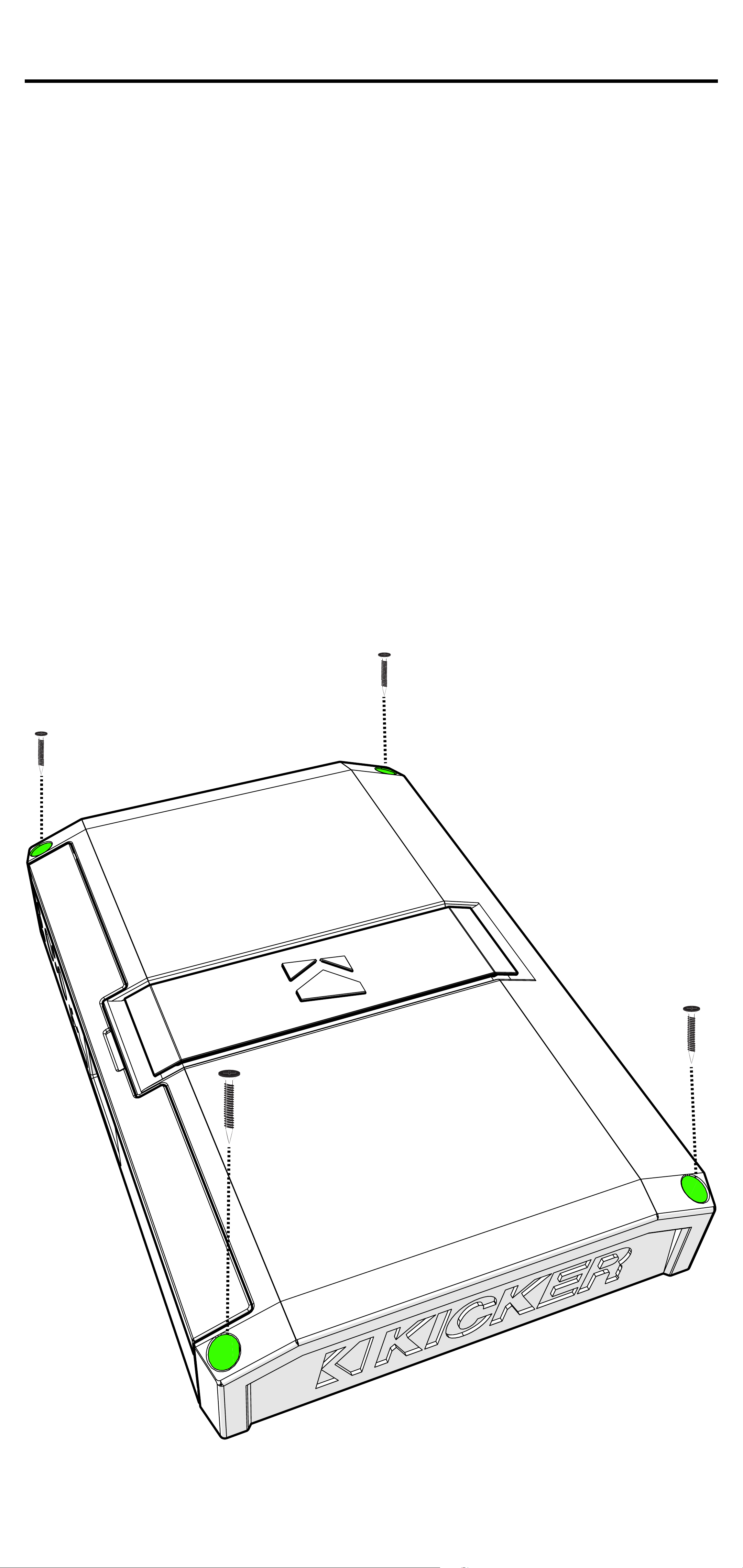
Instalación
Montaje
Elija una ubicación estructuralmente sólida para
montar su amplificador KICKER. Asegúrese
de que no haya objetos detrás del área donde
se introducirán los tornillos. Elija una ubicación
que permita al menos 4” (10cm) de ventilación
abierta para el amplificador. Taladre cuatro
orificios con una broca de 7/64” (3 mm) y utilice
los tornillos del número 8 suministrados para
montar el amplificador.
89Español
Page 90
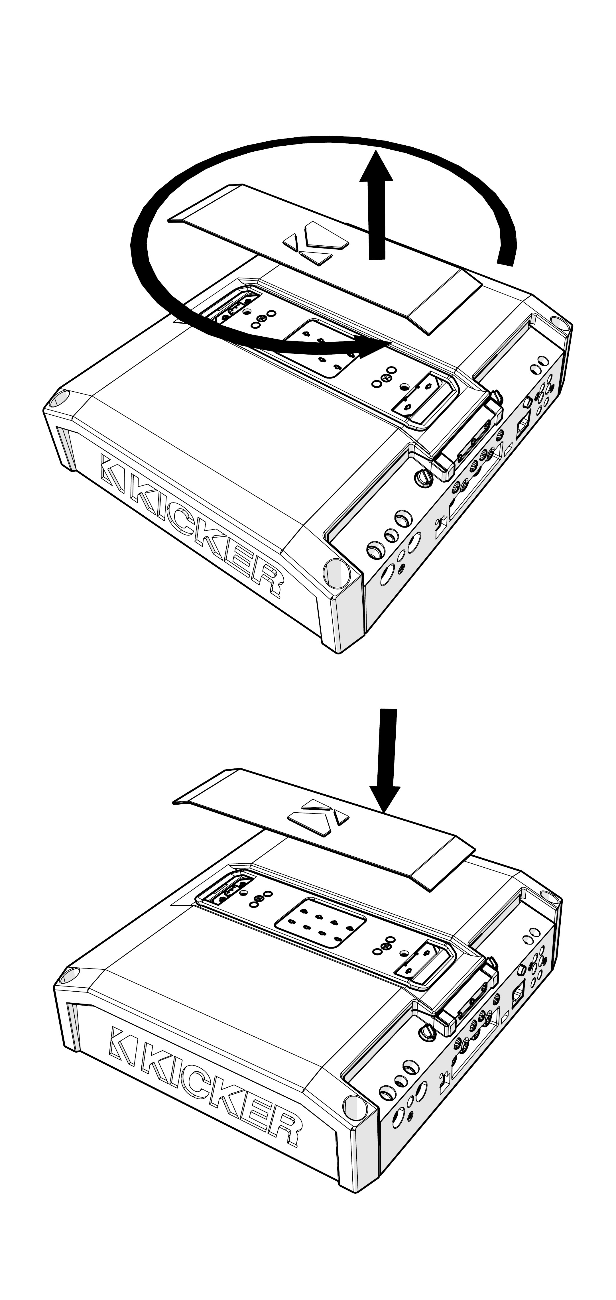
Retire y oriente la placa y la insignia KICKER
magnetizadas según sea necesario.
90Español
Page 91
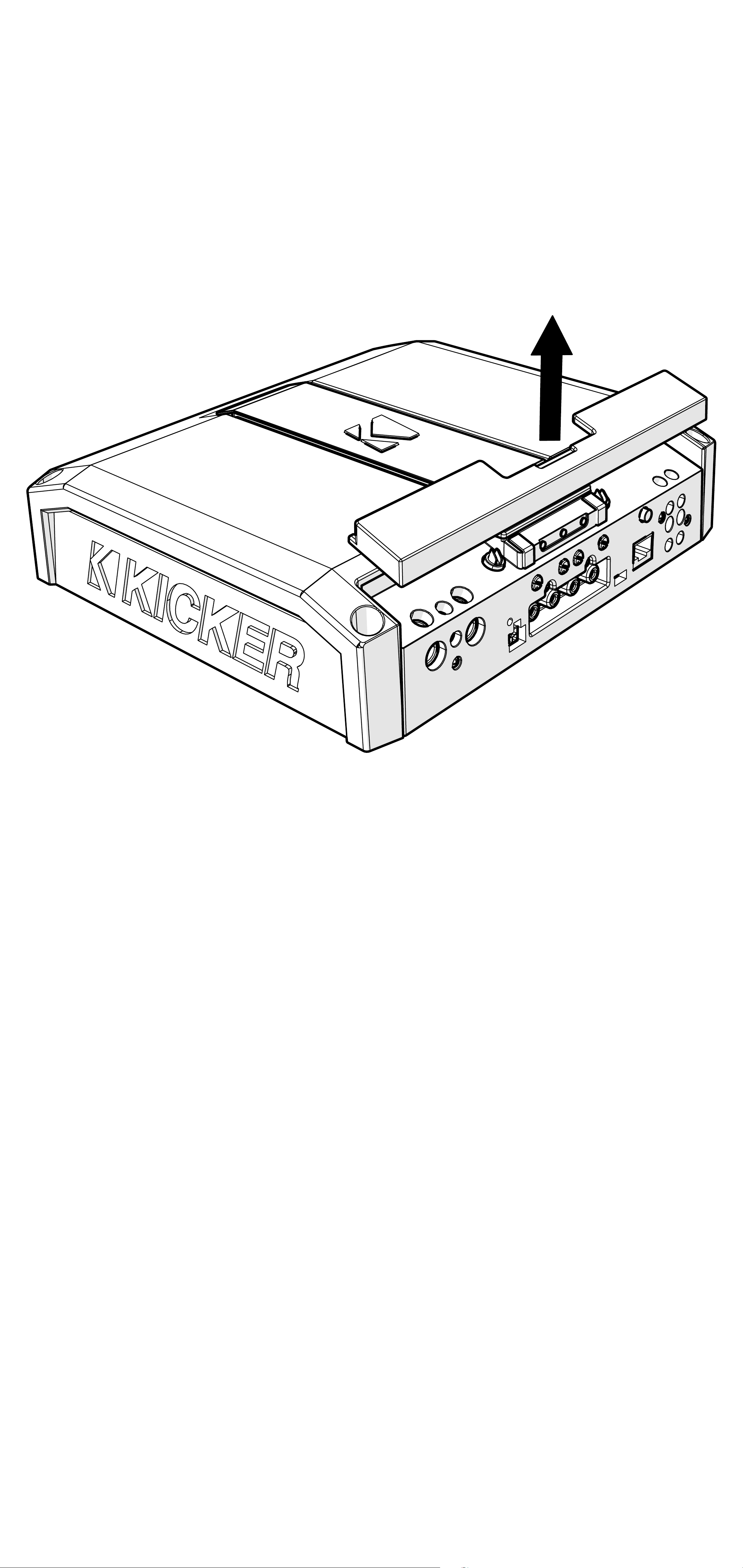
Retire la cubierta del panel superior
magnetizada para acceder a los terminales de
salida de altavoces y de distribución de energía
del amplificador LX, así como a los ajustes de
ganancia e iluminación de acento LED.
91Español
Page 92

Cableado de alimentación
Haga clic aquí para ver los kits
de instalación del amplificador
Modelo Fusible externo
(se vende por separado)
LX850.1 1 x 80amperios Calibre 4 PK4, CK4
LX1250.1 1 x 100amperios Calibre 1/0 PKD1
LX1650.1 1 x 150amperios Calibre 1/0 PKD1
LX3000.1 1 x 200amperios Calibre 1/0 PKD1
Cable de alimentación/
conexión a tierra
Kit de cableado
KICKER
KICKER proporcionará una garantía de tres años para
todos los amplificadores de la serie LX que se compren en
conjunto con un kit* de instalación KICKER que cumpla con
los requisitos.
Esto extiende un año más la garantía estándar. El amplificador y el kit deben
adquirirse de un Distribuidor Autorizado de KICKER.
Usar kits de cableado de baja calidad y especificaciones insuficientes impactará el
rendimiento del amplificador LX. Un kit de instalación KICKER de calidad superior extenderá
la vida útil de los amplificadores LX.
La nueva garantía extendida solo se aplica a los amplificadores y accesorios KICKER que los consumidores adquieran
de Distribuidores KICKER Autorizados en los Estados Unidos de América o sus territorios. Además, solo se aplica
al comprador original de los amplificadores y accesorios KICKER. Se permite una sola extensión de la garantía por
amplificador, sin importar cuantos kits de instalación de amplificador se compren. Este programa no se aplica a los
productos de clase “B” o reacondicionados de fábrica.
Esta oferta es por tiempo limitado, así que consulte a su Distribuidor KICKER Autorizado para conocer los detalles.
*U.S.A. Only | EE.UU. solamente | Nur USA | Les USA Seulement
Desconecte la batería del vehículo para
evitar un cortocircuito eléctrico. Una buena
conexión a tierra es importante. Haga que
elcable de tierra sea corto, de 24” (60 cm)
omenos y, si no está conectado a la batería,
conéctelo a un área de metal sólido y libre de
pintura y corrosión del chasis del vehículo. Se
recomienda agregar un cable de tierra adicional
de este mismo calibre (o mayor) entre el borne
negativo de la batería y el chasis del vehículo.
Mantenga el cable de señal de audio alejado
de los arneses de cableado de fábrica y otros
cables de alimentación. Si necesita cruzar este
cableado, hágalo a un ángulo de 90grados.
92Español
Page 93
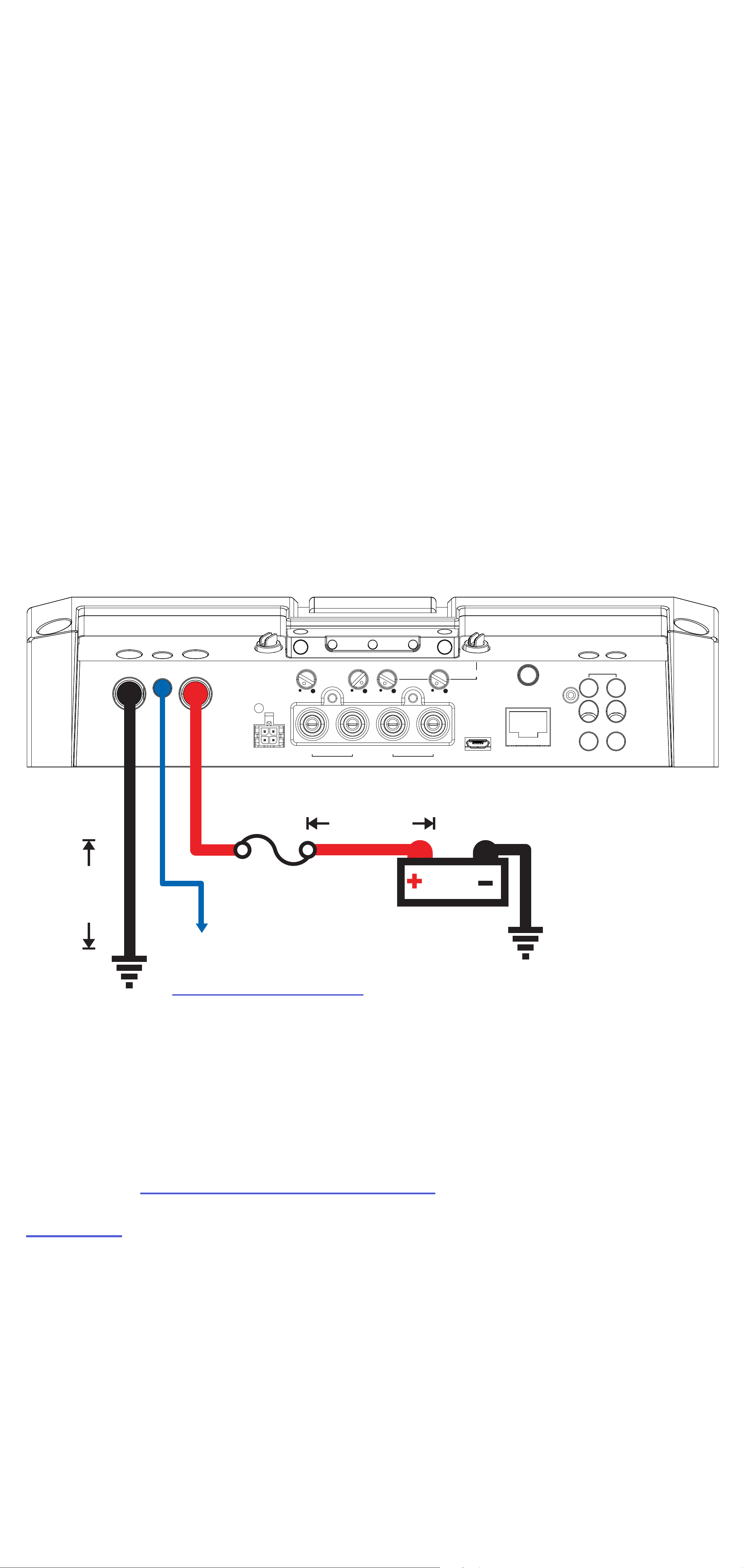
La instalación del fusible debe hacerse lo más
cerca posible de la batería y no más allá de
18”(45 cm) de la batería, y en línea con el
cable de alimentación, que está conectado a
su amplificador LX. Asegúrese de que el cable
de alimentación esté colocado de manera
que no se dañe, se doble ni produzca un
cortocircuito. Si en algún momento necesita
quitar el amplificador del vehículo después de
haberlo instalado, el cable de tierra debe ser
el último cable desconectado del amplificador;
justo lo opuesto a cuando lo instaló.
GND REM +12V
SUBSONIC X-OVER FREQ BANDWIDTH
KICK EQ+
SPEAKER
≤24”
PWR/
PRT
HI-LEVEL
INPUT
10 Hz 80 40 Hz 160 20 Hz 80 1 5
L
fusible
LR R
INPUT OUTPUT
≤18”
(45cm)
12V
REMOTE BASS
+
-
+
-
(60cm)
encendido remoto
(ver la página 97)
batería
conexión a tierra
Consejo profesional: ¡Todo lo que falta
son los subwoofers KICKER y algunos
cables y tendrá una mejora de audio que
dominará cualquier sistema de fábrica! Los
amplificadores KICKER facilitan la actualización
a graves sólidos con su unidad fuente existente
o estándar. Pregunte a su distribuidor sobre las
actualizaciones de KICKER.
93Español
Page 94
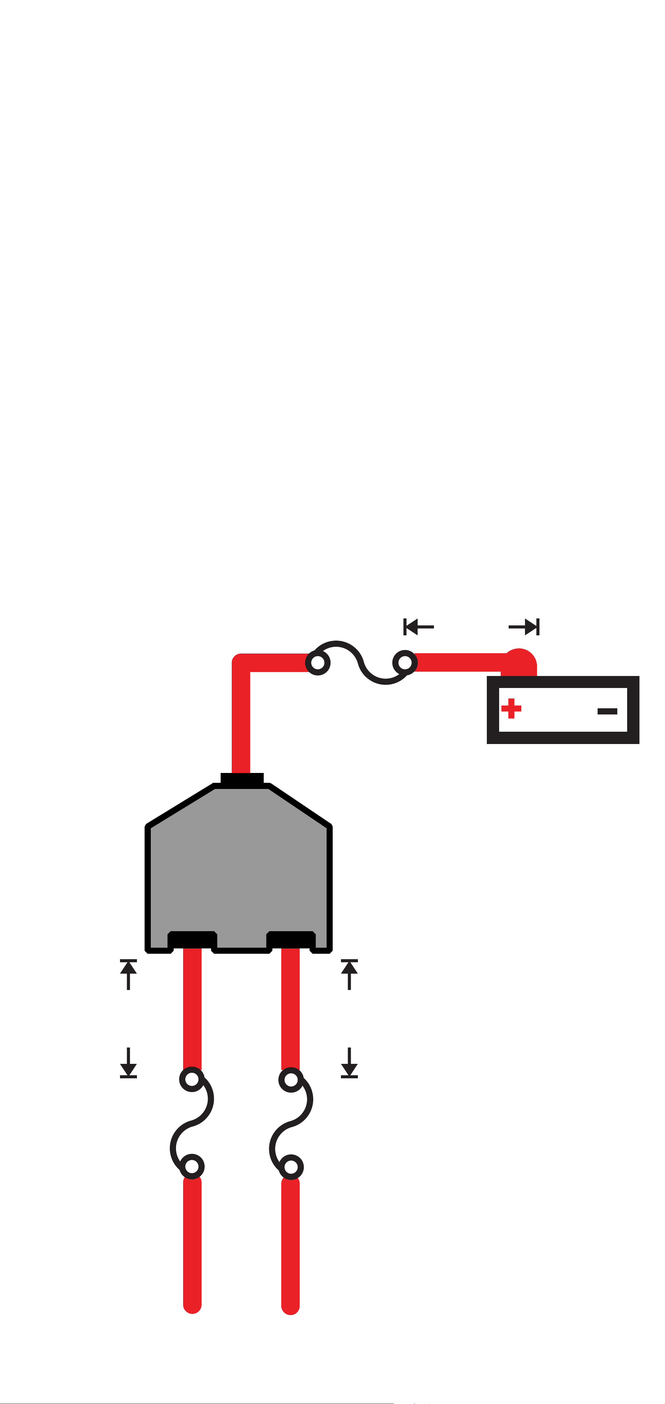
Para múltiples instalaciones de amplificadores
en las que se usen bloques de distribución,
cada amplificador debe tener un fusible con la
clasificación adecuada o un disyuntor instalado
entre el amplificador y el bloque de distribución
a dieciocho pulgadas del bloque o menos, o
enel bloque de distribución, si este proporciona
fusibles. El cable de alimentación principal
también debe tener un fusible entre la batería y
el bloque de distribución, a dieciocho pulgadas
del terminal positivo de la batería o menos, con
un fusible o disyuntor con una clasificación que
al menos iguale la suma de los valores de los
fusibles de los amplificadores individuales, pero
que no exceda la capacidad de su cableado.
(45cm)
fusible externo
≤18”
12V
batería
≤18”
(45cm)
bloque de distribución
de energía
≤18”
(45cm)
fusible
externo
fusible
externo
a amplificadores
94Español
Page 95
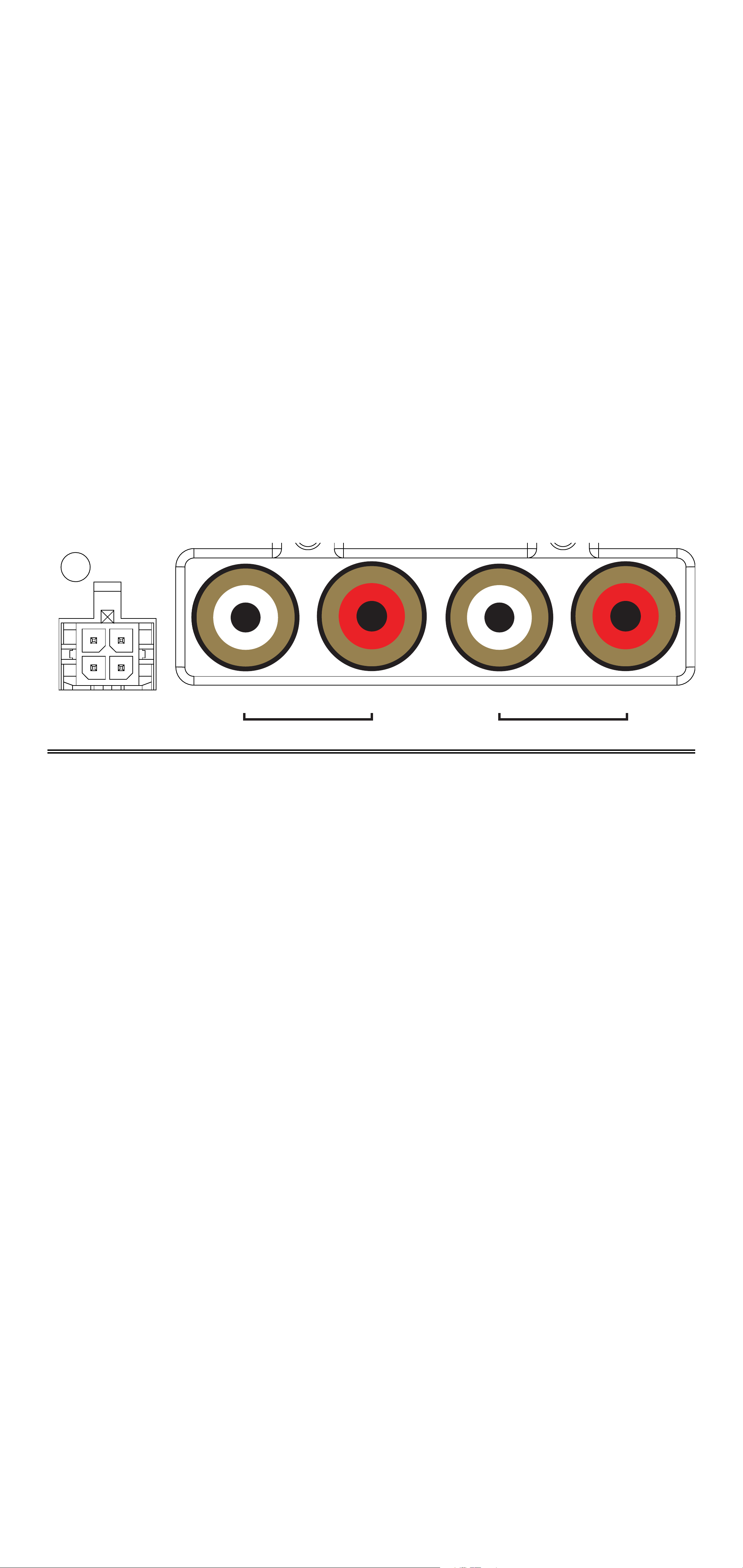
Cableado de entrada
PWR/
PRT
SUBSONIC X-OVER FREQ BANDWIDTH
KICK EQ+
10 Hz 80 40 Hz 160 20 Hz 80 1 5
Las series LX pueden recibir señales de bajo
nivel con las entradas RCA y señales de alto
nivel con el arnés de cableado de entrada de
alto nivel en el panel frontal del amplificador.
Los amplificadores LX Mono también
cuentan con salida RCA para encadenar
convenientemente más amplificadores LX
ensu sistema de audio.
L
HI-LEVEL
INPUT
INPUT OUTPUT
LR R
Los canales de entrada correspondientes a los
colores del arnés de cableado son:
Izquierdo: Blanco, Blanco/Negro
Derecho: Gris, Gris/Negro
95Español
Page 96
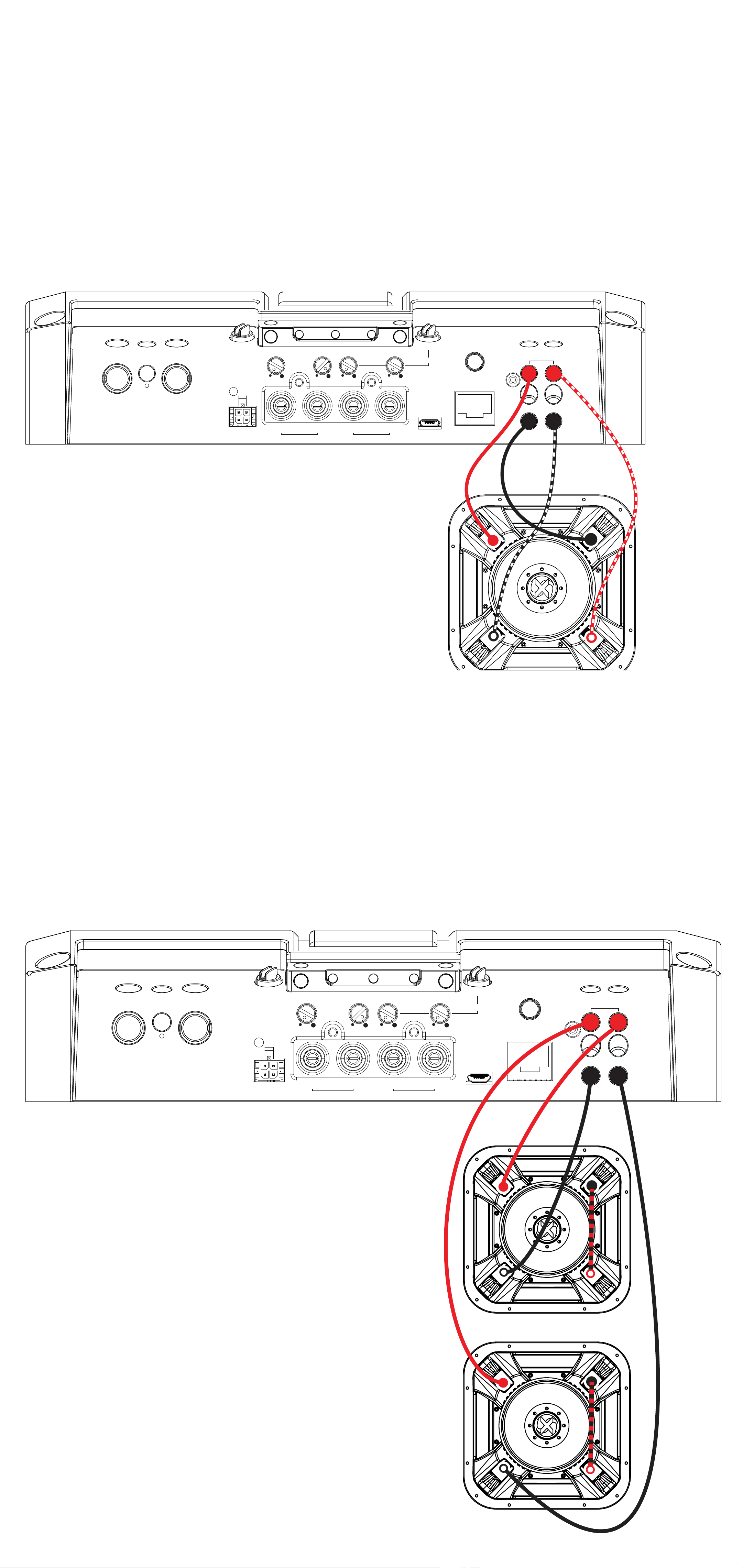
Cableado de subwoofer
Subwoofer L7X individual de doble bobina
de voz de 2Ω cableado en paralelo.
La impedancia final de la carga debe ser de
1Ω como mínimo.
GND REM +12V
PWR/
PRT
HI-LEVEL
INPUT
SUBSONIC X-OVER FREQ BANDWIDTH
10 Hz 80 40 Hz 160 20 Hz 80 1 5
L
INPUT OUTPUT
LR R
KICK EQ+
REMOTE BASS
SPEAKER
+
-
+
-
Dos subwoofers L7X de doble bobina
devoz de 1Ω cableados en serie/paralelo
La impedancia final de la carga debe ser de
1Ω como mínimo
GND REM +12V
PWR/
PRT
HI-LEVEL
INPUT
SUBSONIC X-OVER FREQ BANDWIDTH
10 Hz 80 40 Hz 160 20 Hz 80 1 5
L
INPUT OUTPUT
LR R
KICK EQ+
REMOTE BASS
SPEAKER
+
-
+
-
96Español
Page 97
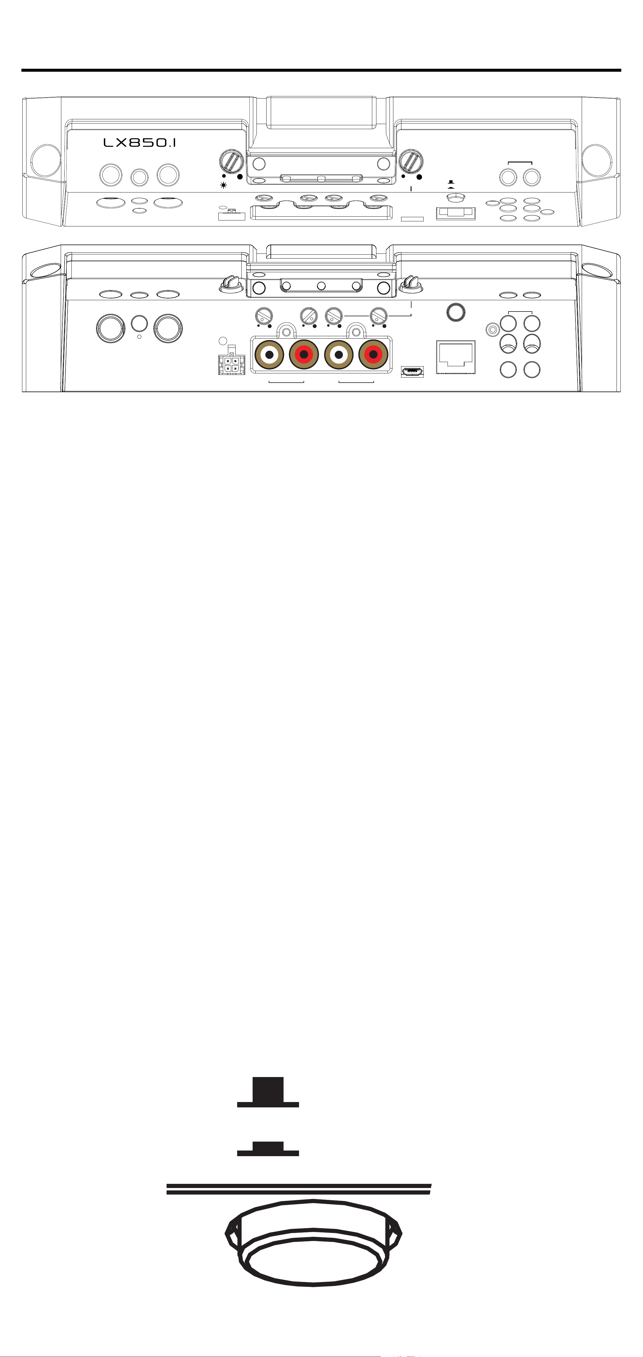
Funcionamiento
DC OFFSET
OFF
ON
L R L R L R
AMP1 AMP2 AMP3
GND REM +12V
GND REM +12V
GAIN
GAIN
MATCH
LO-PASS CENTER
SUBSONIC X-OVER FREQ BANDWIDTH
BASS
BOOST
0 dB 6
KICK EQ+
SPEAKER
DC OFFSET
OFF
ON
SPEAKER
PWR/
PRT
HI-LEVEL
INPUT
10 Hz 80 40 Hz 160 20 Hz 80 1 5
L
INPUT OUTPUT
LR R
+
-
REMOTE BASS
+
-
Encendido automático: La serie LX ofrece
dos modos de encendido automático:
+12V y desviación de CC.
• Encendido remoto: Conecte un cable de calibre 18 desde
el conector de encendido remoto de su unidad fuente
hasta el terminal REM, en el panel final del amplificador LX.
• Encendido con desviación de CC: El modo de
compensación de CC usa el arnés de entrada de alto nivel
para detectar >2,5 V CC desde la salida del parlante de
alto nivel de la unidad fuente cuando se ha encendido.
Para utilizar el modo de desviación de CC, el botón de
encendido/apagado de CC debe estar en la posición ON o
IN. Al utilizar el modo de desviación de CC, el terminal REM
se convierte en una salida conmutada de +12 V (100 mA)
para encender otros amplificadores y dispositivos.
97Español
Page 98

GANANCIA DE ENTRADA: El control de
MATCH
ganancia de entrada no es un control de
volumen. Nivela la salida de la unidad fuente
con la entrada del amplificador. Es posible
obtener la potencia máxima del amplificador
con la ganancia en la posición más baja.
Configurar la ganancia incorrectamente puede
causar una salida distorsionada o daños en
los parlantes y un fallo prematuro.
GND REM +12V
GAIN
GAIN
ADAPTACIÓN DE GANANCIA: En cualquier
sistema de audio, el objetivo es alcanzar
los niveles máximos de entrada y salida sin
distorsión ni saturación. Los ingenieros de
KICKER han eliminado las conjeturas y las
dificultades en cuanto a adaptar el voltaje
desalida de su unidad fuente al amplificador
con la función Adaptación de ganancia. Para
comenzar, tendrá que descargar los tonos de
prueba de KICKER en KICKER.com.
Estos tonos de prueba son ondas sinusoidales
diseñadas para proporcionar una señal
constante para que el amplificador la
referencie. Los diferentes niveles de grabación
están diseñados para ofrecerle la adaptación
de ganancia perfecta para su aplicación.
98Español
Page 99

0dBFS: Diseñado para aplicaciones audiófilas
para ofrecerle una salida de audio sin distorsiones
con el máximo rango dinámico.
5dBFS: Diseñado para aplicaciones normales/
-
cotidianas, habrá menos rango dinámico, pero
mayores niveles potenciales de salida de audio.
Con esta configuración, se puede obtener cierta
saturación ocasional del amplificador.
10dBFS: Diseñado únicamente para
-
aplicaciones de subwoofer, habrá menos rango
dinámico, pero mayores niveles potenciales de
salida de audio. Con esta configuración, se puede
obtener cierta saturación del amplificador.
Después, utilice el siguiente procedimiento
para adaptar con precisión la ganancia de su
amplificador:
1. Desconecte los parlantes del amplificador.
2. Establezca todos los ajustes de EQ y
crossover en plano en su unidad fuente.
3. Reproduzca el archivo descargable de
KICKER.com
4. Suba la unidad fuente al nivel máximo
de volumen sin saturación. Si no puede
determinar esto con precisión, ¾ del volumen
es un buen punto de partida.
5. Aumente la ganancia del amplificador
hasta que se encienda el LED de ganancia.
6. Disminuya la ganancia del amplificador
hasta que se apague el LED de ganancia.
99Español
Page 100

Para usar el método preferido de establecer la
ganancia de entrada mediante un voltímetro u
osciloscopio, primero apague el amplificador y
desconéctele todos los parlantes. Mueva por
completo la perilla de ganancia a la posición de
apagado (en sentido antihorario) y apague todos
los crossovers o colóquelos en su configuración
menos efectiva. Si hay un accesorio de graves
remoto conectado al amplificador, enciéndalo
por completo (girándolo en sentido horario).
Asegúrese de que todas las configuraciones
de EQ y DSP de la unidad fuente, como los
graves, los agudos, el fader, la posición de
reposo, etc., estén establecidas en lineal, plana,
centrada o apagada. Encienda el amplificador.
Con un osciloscopio, pruebe la señal que
proviene de la unidad fuente y reproduzca una
onda sinusoidal de 0 dB a través de su unidad
fuente y aumente el volumen hasta que vea
que la forma de onda se recorta ligeramente.
Baje la unidad principal un nivel, ya que este
es el nivel máximo de volumen sin saturación
de su unidad fuente. Puede descargar gratis
pistas de onda sinusoidal de KICKER.com,
enla pestaña “Soporte”. Use la onda sinusoidal
de 50Hz para establecer la ganancia de un
subwoofer y la onda sinusoidal de 1kHz para
los parlantes de rango completo. Configure el
voltímetro u osciloscopio para que mida voltaje
de CA. Coloque las sondas del voltímetro en los
terminales de salida del parlante del amplificador.
Con la onda sinusoidal en reproducción, gire
lentamente la perilla de ganancia en sentido
horario y observe el aumento del voltaje de CA
en el voltímetro.
100Español
 Loading...