


 Loading...
 OT401
OT401
 OT801
OT801
User's Manual

ENGLISH
Contents |
|
Contents |
|
About this Manual..................................................................................................................... |
5 |
FCC Compliance Statement....................................................................................................... |
5 |
Copyright................................................................................................................................... |
5 |
Safety Information..................................................................................................................... |
6 |
Chapter 1: Product Overview.............................................................................. |
7 |
1.1 Features............................................................................................................................... |
7 |
1.2 Package Contents................................................................................................................ |
7 |
1.3.1 Front Panel............................................................................................................... |
8 |
1.3.2 Rear Panel................................................................................................................ |
9 |
4-Channel DVR......................................................................................................... |
9 |
8-Channel DVR......................................................................................................... |
9 |
1.4 Remote Control................................................................................................................. |
10 |
1.5 Mouse................................................................................................................................ |
11 |
Chapter 2: Installation....................................................................................... |
12 |
2.1 Installing the Hard Disk Drive............................................................................................ |
12 |
2.2 Connecting the Power....................................................................................................... |
13 |
2.3 Connecting to Monitors..................................................................................................... |
13 |
2.3.1 BNC Connection..................................................................................................... |
13 |
2.3.2 VGA Connection..................................................................................................... |
14 |
2.4 Connecting the Cameras................................................................................................... |
14 |
2.4.1 BNC Connection..................................................................................................... |
14 |
2.4.2 RS-485 Connection................................................................................................. |
15 |
2.5 Connecting the Microphones............................................................................................ |
16 |
2.6 Connecting to Network..................................................................................................... |
17 |
2.7 Connecting to Other Devices............................................................................................. |
18 |
2.8 Connecting to Speakers..................................................................................................... |
18 |
Chapter 3: Getting Started................................................................................. |
19 |
3.1 Starting Up......................................................................................................................... |
19 |
3.2 Shutting Down................................................................................................................... |
19 |
3.3 The Main Screen................................................................................................................ |
20 |
3.3.1 Screen Icons........................................................................................................... |
20 |
3.3.2 Virtual Keyboard.................................................................................................... |
21 |
3.3.3 Locking the Screen................................................................................................. |
21 |
3.3.4 Pop-up Menu......................................................................................................... |
22 |
3.3.5 On Screen Display (OSD) menu.............................................................................. |
23 |
3.4 Screen Modes.................................................................................................................... |
24 |
3.4.1 Live View................................................................................................................ |
24 |
3.4.2 Multi Picture Mode................................................................................................ |
25 |
3.4.3 Picture-in-Picture (PIP) Mode................................................................................ |
25 |
3.4.4 Auto Switch View................................................................................................... |
26 |
3.5 Using PTZ Controls............................................................................................................. |
27 |
3.5.1 Cruise Mode........................................................................................................... |
28 |
3.6 Zoom.................................................................................................................................. |
28 |
3.7 Manual Recording............................................................................................................. |
29 |
3.8 Turning Mute On............................................................................................................... |
29 |
DVR User’s Manual |
|
2

|
Contents |
Chapter 4: Using the DVR.................................................................................. |
30 |
4.1 Setting the Camera............................................................................................................ |
30 |
4.1.1 Display Setup.......................................................................................................... |
30 |
Color Setup............................................................................................................ |
31 |
4.1.2 Recording Setup..................................................................................................... |
31 |
Schedule Recording............................................................................................... |
32 |
4.2 Setting the Network.......................................................................................................... |
33 |
4.2.1 DHCP...................................................................................................................... |
33 |
4.2.2 PPPoE..................................................................................................................... |
33 |
4.2.3 Static IP.................................................................................................................. |
34 |
4.2.4 DDNS...................................................................................................................... |
35 |
4.3 Viewing Recorded Videos.................................................................................................. |
36 |
4.3.1 Searching and Playing Videos................................................................................. |
36 |
4.3.2 Backing up Videos.................................................................................................. |
37 |
4.3.3 Viewing and Exporting Log..................................................................................... |
38 |
4.4 Setting the Device.............................................................................................................. |
39 |
4.4.1 Storage Device Setup............................................................................................. |
39 |
Setting HDD........................................................................................................... |
39 |
Formatting HDD..................................................................................................... |
40 |
Formatting USB drive............................................................................................. |
40 |
4.4.2 Setting Alarms........................................................................................................ |
41 |
Configure Alarm Settings....................................................................................... |
41 |
Email Alarm Notifications...................................................................................... |
42 |
4.4.3 PTZ Setup............................................................................................................... |
42 |
4.4.4 Setting Up Mobile Devices..................................................................................... |
43 |
4.4.5 Setting Motion Detection....................................................................................... |
44 |
4.5 System Settings.................................................................................................................. |
45 |
4.5.1 Date and Time Settings.......................................................................................... |
45 |
Synchronizing Time with NTP Server..................................................................... |
45 |
Setting Daylight Saving Time.................................................................................. |
46 |
4.5.2 User and Password Settings................................................................................... |
47 |
Changing the Password......................................................................................... |
47 |
Configuring Other Users........................................................................................ |
48 |
Authorizing Other Users........................................................................................ |
48 |
4.5.3 Video and Audio Settings....................................................................................... |
49 |
Setting the Video Output....................................................................................... |
49 |
Setting the Volume................................................................................................ |
49 |
Setting the Privacy................................................................................................. |
50 |
4.5.4 Language Setting.................................................................................................... |
51 |
4.5.5 System Information................................................................................................ |
52 |
4.5.6 Maintenance Settings............................................................................................ |
52 |
Manual Reboot and Power Off.............................................................................. |
52 |
Set Auto Maintenance........................................................................................... |
53 |
Update System Firmware...................................................................................... |
54 |
Load Default Settings............................................................................................. |
54 |
Chapter 5: KGUARD Web Client......................................................................... |
55 |
5.1 Login.................................................................................................................................. |
55 |
5.2 The Interface..................................................................................................................... |
56 |
5.3 Live Viewing....................................................................................................................... |
57 |
|
DVR User’s Manual |
ENGLISH
3

ENGLISH
Contents |
|
5.3.1 Switching Screen Modes........................................................................................ |
57 |
5.3.2 Viewing and Recording........................................................................................... |
58 |
Using Play Controls................................................................................................ |
58 |
Recording Individual Channels Manually............................................................... |
58 |
Taking Snapshots................................................................................................... |
58 |
Using PTZ Controls................................................................................................. |
59 |
5.4 Searching and Playing Recorded Videos............................................................................ |
60 |
5.4.1 Searching and Playing Videos................................................................................. |
60 |
5.4.2 Downloading Recorded Videos.............................................................................. |
61 |
5.4.3 Converting Video Format....................................................................................... |
61 |
5.5 Setup................................................................................................................................. |
62 |
5.5.2 Record Settings...................................................................................................... |
63 |
Setting the Recording Schedule............................................................................. |
63 |
5.5.3 Alarm Settings........................................................................................................ |
65 |
Motion Detection Setup........................................................................................ |
65 |
Alarm Setup........................................................................................................... |
66 |
5.5.4 PTZ Settings............................................................................................................ |
67 |
5.5.5 Network Settings.................................................................................................... |
68 |
Setting Up with TCP/IP - Static IP........................................................................... |
68 |
Setting Up with TCP/IP - PPPoE.............................................................................. |
68 |
Setting Up TCP/IP - DHCP....................................................................................... |
69 |
Setting Up DDNS.................................................................................................... |
70 |
Setting Up Email.................................................................................................... |
71 |
Setting Up Mobile Device...................................................................................... |
72 |
5.5.6 System Settings...................................................................................................... |
73 |
Managing User Accounts....................................................................................... |
73 |
Advanced Settings................................................................................................. |
74 |
5.5.7 System Information................................................................................................ |
75 |
Chapter 6: Using KView Series Software............................................................ |
76 |
6.1 KView................................................................................................................................. |
76 |
6.1.1 KView on Android® Phones.................................................................................... |
76 |
6.1.2 KView on iPhone®.................................................................................................. |
77 |
6.2 KViewHD............................................................................................................................ |
79 |
6.2.1 KViewHD on Android® Tablets................................................................................ |
79 |
6.2.2 KViewHD on iPad®.................................................................................................. |
80 |
6.3 KView Center..................................................................................................................... |
81 |
6.4 KView Series Specifications............................................................................................... |
82 |
Chapter 7: Troubleshooting & FAQ.................................................................... |
83 |
7.1 Troubleshooting................................................................................................................. |
83 |
7.2 Frequently Asked Questions.............................................................................................. |
84 |
Appendix: Specifications................................................................................... |
85 |
DVR User’s Manual
4

Preface
About this Manual
The material in this document is for information purpose and is subject to change without prior notice. We made every effort to ensure that this user’s manual is accurate and complete. However, no liability is assumed for any errors and omissions that may have occurred.
FCC Compliance Statement
This equipment has been tested and found to comply with the limits for a Class B digital device, pursuant to Part 15 of the FCC Rules. These limits are designed to provide reasonable protection against harmful interference in a residential installation. This equipment generates uses and can radiate radio frequency energy and, if not installed and used in accordance with the instructions, may cause harmful interference to radio communications. However, there is no guarantee that interference will not occur in a particular installation. If this equipment does cause harmful interference to radio or television reception, which can be determined by turning the equipment off and on, the user is encouraged to try to correct the interference by one or more of the following measures:
•Reorient or relocate the receiving antenna.
•Increase the separation between the product and receiver.
•Connect the product into an outlet on a circuit different from that to which the receiver is connected.
•Consult the dealer or an experienced radio/TV technician for help.
Declaration of Conformity
This device complies with part 15 of the FCC Rules. Operation is subject to the following two conditions:
1.This device may not cause harmful interference.
2.This device must accept any interference received, including interference that may cause undesired operation.
Copyright
Limitation of Liability
•This publication is provided “AS IS” without warranty of any kind, either expressed or implied, including but not limited to, the implied warranties of merchantability, fitness for any particular purpose, or noninfringement of a third party’s rights.
•This publication may include technical inaccuracies or typographical errors. Changes may be made to the information herein, at any time, for publication improvements and/or of the corresponding device(s).
Disclaimer of Warranty
In no event shall the supplier be liable to any party or any person, except for replacement or reasonable maintenance of the product, for the cases, including but not limited to the following:
•Any damage or loss, including but without limitation, direct or indirect, special, consequential or exemplary, arising out of or relating to the device;
•Personal injury or any damage caused by inappropriate use or negligent operation of the user;
•Unauthorized disassemble, repair or modification of the device by the user;
•Any problem, consequential inconvenience, or loss or damage, arising out of combining the system with the devices of a third party;
•Any claim or action for damages, brought by any person or organization being a photogenic subject, due to violation of privacy with the result of pictures from a surveillance camera, including saved data, for some reason, becomes public or is used for the purpose other than for surveillance.
ENGLISH
DVR User’s Manual
5
ENGLISH
Preface
Safety Information
Warning |
Caution |
This is the symbol for indicating any potential hazard, |
The lighting flash with an arrow head symbol, in an |
risk or condition requiring special attention. |
equilateral triangle, is intended to alert the user. |
The user needs to refer to the important operating |
There is dangerous “voltage” presence near by the |
and maintenance or servicing instructions. |
product’s enclosure which may be risk of person. |
Safety Precautions
•Do not touch live electrical parts.
Electric shock can be avoided. Follow the recommended practices listed below. Faulty installation, improper grounding, and incorrect operation and maintenance of electrical equipment are always sources of danger.
•Do not try to install equipment outdoor, during strong wind and rain.
•Do not install or remove equipment outdoor, when raining.
•Do not try to install or operate any equipment, during a thunderstorm.
•Always ground all electrical equipment and the work platform.
Prevent accidental electrical shocks. Connect power source, control cabinets, and work platform to an approved electrical ground.
•Always use the correct cable size.
Sustained overloading will cause cable failure and result in possible electrical shock or fire hazard. Work cable should be the same rating as the factory.
•Always keep cables and connectors in good condition.
Improper or worn electrical connections can cause short circuits and can increase the chance of an electrical shock. Do not use worn, damaged, or bare cables.
•Always avoid open-circuit voltage.
The added voltages increase the severity of electric shock hazard.
•Always wear insulated gloves while you adjust equipment.
Electric power should be turned off and insulated gloves should be worn when making any equipment adjustment to assure shock protection.
•Always wear protective clothing such as long sleeve shorts while you are installing or removing equipment.
•Always wear high, snug fitting shoes.
•Always wear clean clothes without grease or oil.
•Protect neighboring workers from exposure to arc radiation.
•Always wear long trousers or jeans while you are installing or removing equipment.
•Always wear safety helmet or hard head and safety shoes before work.
•Always keep the equipment in dry places.
•Always wear safety harnesses/belt while you work in high places.
•Always wear dry clothing and avoid moisture and water.
•Always wear Public Safety Vest, while you work at night.
•Make sure all electrical connections are tight, clean, and dry.
•Make sure that you are well insulated to eliminate electric static charge.
•Always wear dry gloves, rubber-soled shoes, or stand on a dry board or platform.
•Always follow recognized safety standards.
•Always wear correct eye, ear, and body protection.
•Always have second person on-site, while you work in dark, poor ventilation, or high places.
•Make sure that you are well protected against arc flashes, mechanical injury, or other mishaps.
•Make sure that the polarity of wire is correct before installing equipment.
•Always handle equipment with care.
•Do not block the ventilation of equipment.
•Do not put the magnetic parts around the equipment.
•Do not put the objects on top of the equipment.
DVR User’s Manual
6
Chapter 1: Product Overview
Chapter 1: Product Overview
1.1 Features
This device supports the following features:
•H.264 Compression and Dual Stream Network Transmission
•Supports D1 Recording and Playback
•User-friendly GUI (Graphical User Interface) & USB Mouse Control for Program Menus
•Supports Simultaneous Multi-Channel Playback
•Multiplex Operation (Supports Live View, Record, Playback and Backup of Video)
•USB Port Supports USB Flash Drive Backup
•Built-in RS-485 port for PTZ control
•Remote Monitoring and Control via KGUARD-exclusive KView Software (Symbian, Windows Mobiles, iPhone and Android phones/tablets)
•Online surveillance via IE browser with audio
•Event-Triggered Email Notification
•Supports Network Time Protocol (NTP)
•Supports up to 2TB SATA HDD
•Privacy Mask for Private Area Protection (Max. 4 Areas in Each Channel)
•Available for Widescreen Screen
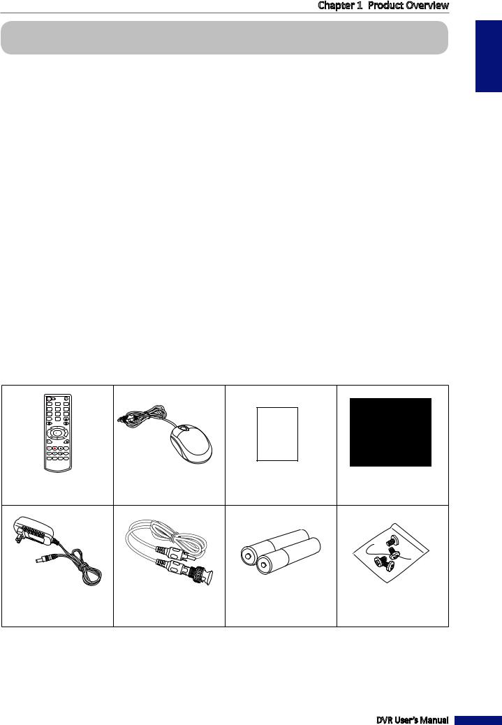
1.2 Package Contents
The following items come with your package. If any of them is missing or damaged, please contact your retailer.
1 |
2 |
3 |
4 |
5 |
6 |
7 |
8 |
9 |
PTZ |
0 |
|
|
|
Quick Guide |
ESC |
|
MENU |
STARTREC STOPREC |
|
|
|
|
F1 |
F2 |
|
|
Remote Control |
Mouse |
Quick Guide |
CD-ROM |
Power Supply |
BNC to RCA Cable |
Batteries* |
HDD Screw Kit |
* Not available in all countries.
DVR User’s Manual
ENGLISH
7
ENGLISH
Chapter 1: Product Overview
1.3 Parts and Functions
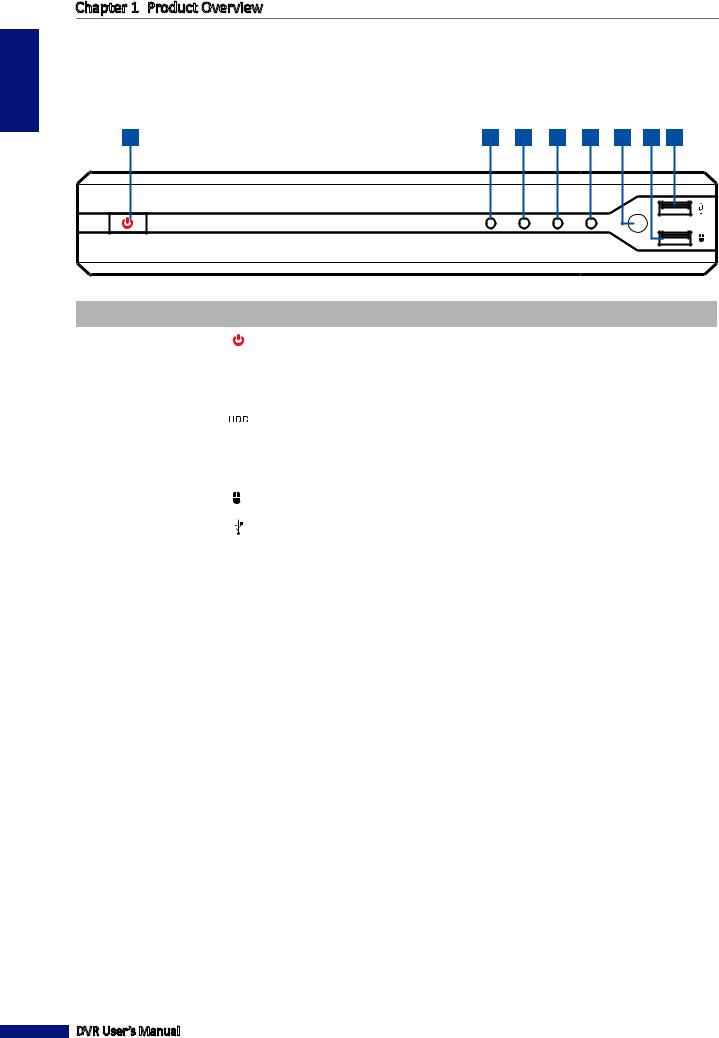
1.3.1 Front Panel
1 |
2 |
3 |
4 |
5 |
6 |
67 |
8 |
GUARD |
|
|
|
|
|
|
|
K SECURITY |
|
|
|
|
|
|
|
|
PWE |
LINK |
HDD |
|
REC |
|
|
4 Channel H.264 Digital Video Recorder
No. |
Item |
Icon |
Description |
|
|
|
|
1 |
Power Button |
|
Press the button to turn the DVR on or off. |
|
|
|
|
2 |
Power Indicator |
PWE |
Lights green to indicate the power is turned on. |
|
|
|
|
3 |
Link Indicator |
LINK |
Lights amber to indicate a link is established. |
|
|
|
|
4 |
HDD Indicator |
|
Lights red when the HDD is being accessed. |
|
|
|
|
5 |
Record Indicator |
REC |
Lights red when recording is in progress. |
|
|
|
|
6 |
IR Receiver |
- |
Receives the remote control signals. |
|
|
|
|
7 |
USB Mouse Port |
|
Connects the USB mouse. |
|
|
|
|
8 |
USB Port |
|
Connects other USB memory devices such as a flash disk. |
|
|
|
|
DVR User’s Manual
8
Chapter 1: Product Overview
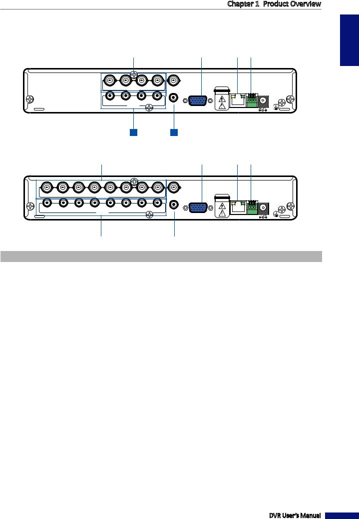
1.3.2 Rear Panel
4-Channel DVR
1 |
|
2 |
|
3 |
|
4 |
|
5 |
|
6 |
|
|
|
|
|
|
|
|
|
|
|
|
|
CH4 |
CH3VIDEO IN CH2 |
CH1 |
VIDEO OUT |
CAUTION |
A B G |
||
|
|
|
|
|
RISK |
OF ELECTRIC SHOCK |
|
|
|
|
|
|
DO NOT OPEN |
||
AIN4 |
AIN3 |
AIN2 |
AIN1 |
AUDIO OUT |
|
|
|
|
AUDIO IN |
|
|
VGA |
|
|
|
|
|
|
|
|
|
||
|
|
|
|
|
NETWORK |
RS485 |
|
|
|
|
|
|
|
||
7 8
8-Channel DVR
1 |
|
2 |
|
3 |
|
4 |
|
5 |
|
6 |
|
|
|
|
|
|
|
|
|
|
|
|
|
CH8 |
CH7 |
CH6 |
CH5VIDEO IN CH4 |
CH3 |
CH2 |
CH1 |
VIDEO OUT |
|
CAUTION |
A B G |
|
|
|
|
|
|
|
|
|
|
|
RISK OF ELECTRIC SHOCK |
|
|
|
|
|
|
|
|
|
|
|
DO NOT OPEN |
|
AIN8 |
AIN7 |
AIN6 |
AIN5 |
AIN4 |
AIN3 |
AIN2 |
AIN1 |
AUDIO OUT |
|
|
|
|
|
|
AUDIO IN |
|
|
|
VGA |
|
|
||
|
|
|
|
|
|
|
|
|
|||
|
|
|
|
|
|
|
|
|
NETWORK |
RS485 |
|
|
|
|
|
|
|
|
|
|
|
||
|
|
|
7 |
|
8 |
|
|
|
|
|
|
|
|||
No. |
Connector |
Description |
|
|
|||
|
|
|
|||||
1 |
Video input |
8-Channel DVR: Connects to a maximum of 8 video input devices (BNC). |
|||||
4-Channel DVR: Connects to a maximum of 4 video input devices (BNC). |
|||||||
|
|
||||||
|
|
|
|||||
2 |
Video output |
Connects to a monitor output via BNC. |
|||||
|
|
|
|
|
|||
3 |
VGA output |
Connects to a VGA monitor. |
|
|
|||
|
|
|
|
|
|||
4 |
LAN |
Connects to LAN via RJ-45. |
|
|
|||
|
|
|
|||||
5 |
RS-485 |
Connects to a Speeddome camera via RS-485. |
|||||
|
|
|
|
|
|||
6 |
Power |
Connects to the power adapter. |
|
|
|||
|
|
|
|||||
7 |
Audio input |
8-Channel DVR: Connects to a maximum of 8 audio input via RCA. |
|||||
|
4-Channel DVR: Connects to a maximum of 4 audio input via RCA. |
||||||
|
|
||||||
|
|
|
|||||
8 |
Audio output |
Connects to an audio output via RCA. |
|||||
|
|
|
|
|
|
|
|
DVR User’s Manual
ENGLISH
9
ENGLISH
Chapter 1: Product Overview
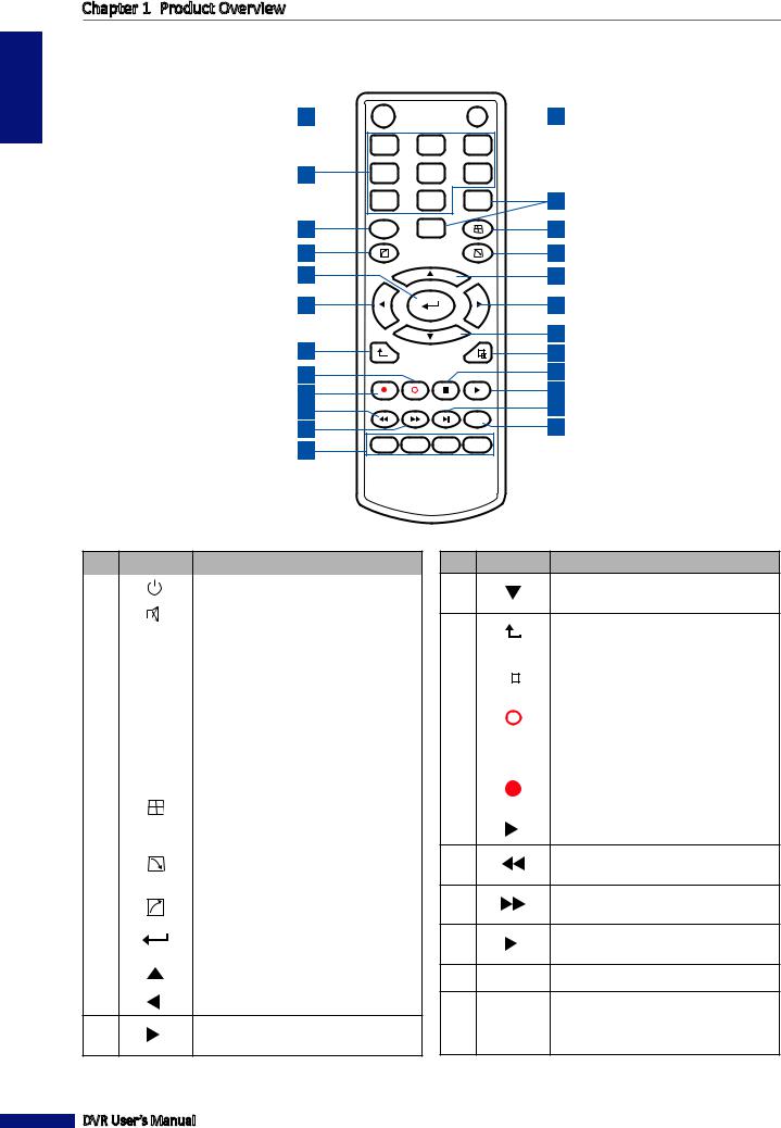
1.4 Remote Control
1 


 2
2
|
1 |
2 |
3 |
|
3 |
4 |
5 |
6 |
|
|
7 |
8 |
9 |
4 |
5 |
PTZ |
0 |
|
6 |
7 |
|
|
|
8 |
9 |
|
|
|
10 |
11 |
|
|
|
12 |
|
|
|
|
13 |
14 |
|
|
|
15 |
16 |
ESC |
|
MENU |
17 |
|
|
|
||
18 |
|
|
|
19 |
20 |
STARTREC |
STOPREC |
|
22 |
|
|
|
||
21 |
|
|
F1 |
23 |
|
|
|
||
24 |
F2 |
|
|
|
|
|
|
|
No. |
Icon |
Description |
|
|
|
1 |
|
Press to start manual recording. |
|
|
|
2 |
|
Press to turn mute on or off. |
|
|
|
|
|
Numeric keys |
3 |
1-8 |
Press to display the channel in full |
|
|
screen. |
|
|
|
|
|
Numeric keys |
4 |
0, 9 |
Press ”0” key to lock or unlock the |
|
|
current screen. |
|
|
|
5 |
PTZ |
Press to configure PTZ settings. |
|
|
|
|
|
Press to display a 4 x 4 channel |
6 |
|
display. Press repeatedly to scroll to |
|
|
other channels. |
|
|
|
|
|
Press to display the pop-up menu. |
7 |
|
See “3.3.4 Pop-up Menu” on page |
|
|
22. |
|
|
|
8 |
|
Press to close the pop-up menu. |
|
|
|
9 |
|
Press to enter the selected menu |
|
item and edit the setting. |
|
|
|
|
|
|
|
10 |
|
Press to move up in the OSD menu. |
|
|
|
11 |
|
Press to move left in the OSD menu. |
12Press to move right in the OSD menu.
DVR User’s Manual
No. Icon Description
13Press to move down in the OSD menu.
14 |
|
|
|
Press to exit the Main Menu or the |
|
ESC |
Playback screen. |
||||
|
|||||
|
|
|
|
|
|
15 |
|
|
|
Press to display the Main Menu. |
|
|
|
|
|||
MENU |
|||||
|
|
||||
|
|
|
|
|
|
16 |
STOPREC |
Press to stop recording. |
|||
|
|
|
|
|
|
17 |
|
|
|
Press to pause playback. |
|
|
|
|
|||
|
|
|
|
|
|
18 |
STARTREC |
Press start recording. |
|||
|
|
|
|
|
|
19 |
|
|
|
Press to play recorded video. |
|
20Press to rewind video playback (x2, x4, x8).
21Press to fast forward video playback (x2, x4, x8).
22 |
|
Press to pause video playback or |
|
||
|
enter frame-playback mode. |
|
|
|
23F1 Reserved key
24F2 Reserved keys
10
Chapter 1: Product Overview
1.5 Mouse
The DVR is supplied with a USB mouse that you can use to operate the DVR. Simply plug in the supplied mouse into the USB mouse connector at the rear panel of the device.
Mouse Operation |
Description |
|
|
Left-click |
In OSD menu, click the left button to select and edit the setting. |
|
|
Right-click |
In preview mode, click the right button to display the pop-up menu. |
|
|
|
In main menu or sub menu mode, click the right button to exit the current menu. |
|
|
Double-click the Left button |
Double-click the live image of any channel for full screen display. Double-click the left |
|
button again to return to the window-display of all cameras. |
|
|
Drag an area/line |
In motion mode, use this function to select motion area. |
|
|
|
In [Color Setup] menu mode, it will adjust color control bar. |
|
|
DVR User’s Manual
ENGLISH
11
ENGLISH
Chapter 2:
 Installation
Chapter 2: Installation
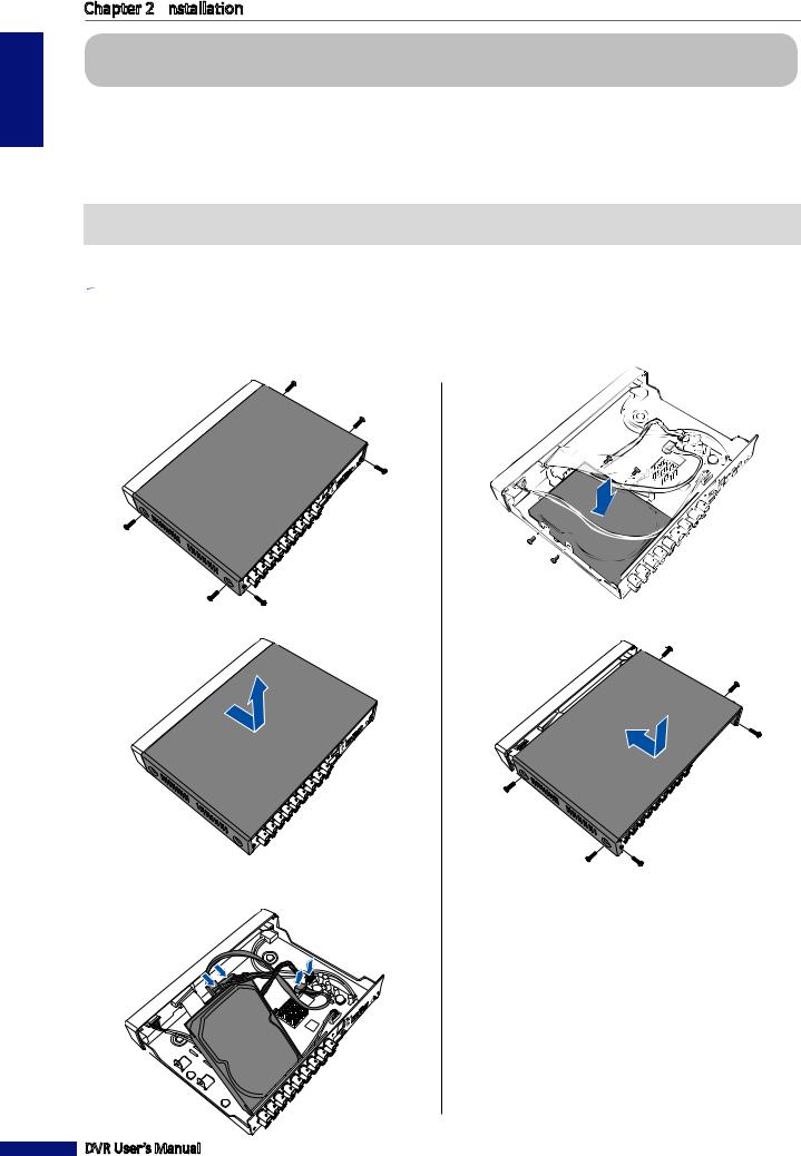
2.1 Installing the Hard Disk Drive
Depending on the package you have purchased, the hard disk drive may be included in the full package. If it is not pre-installed, follow the installation instructions on this user manual.
 DO NOT install or remove hard disk drive while the device power is turned on.
The 4-channel / 8-channel DVR supports one 3.5” SATA hard disk drive. To install the HDD, follow the steps below.
 Note:
Note:
The illustrations below show an 8-channel DVR, same procedures apply to a 4-channel DVR.
1 Loosen the screws on the left, right, and rear sides as |
4 Attach the HDD to the bracket using 4 screws. |
shown. |
|
2 Push back then lift up the cover to remove it.
5 Attach the cover and screws back in place.
3 Connect the data and power cables to the hard disk drive (HDD) and the DVR.
DVR User’s Manual
12
Chapter 2:
 Installation
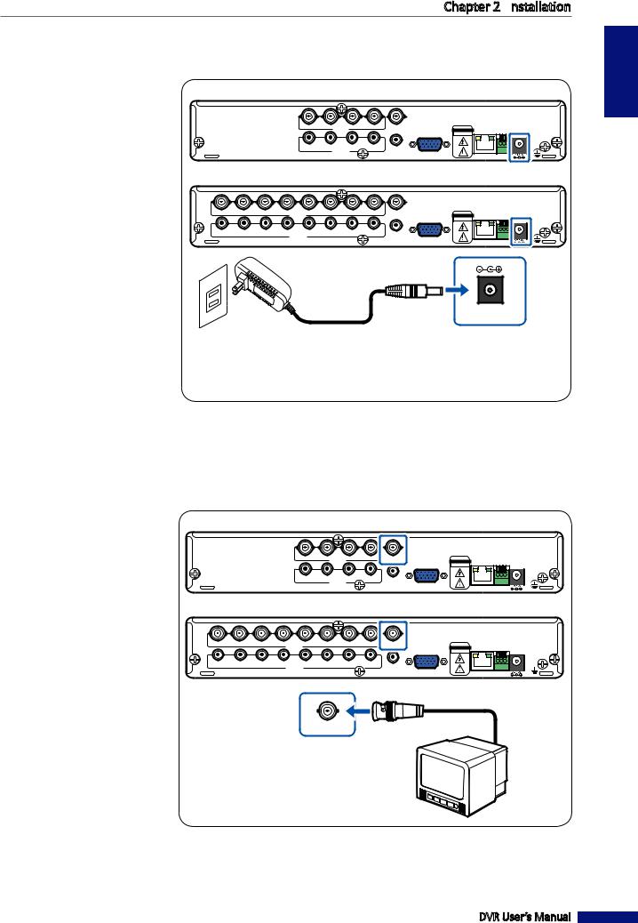
2.2 Connecting the Power
Use only the supplied power adapter and power cord that came with the DVR.
1 Connect one end of the power supply to the power connector on the back of the DVR.
2 Plug the other end of the power
supply into the wall outlet.
3 Press the Power  button to turn on the DVR.
4-Channel DVR
|
|
|
|
CH4 |
CH3VIDEO IN CH2 |
CH1 |
VIDEO OUT |
CAUTION |
A B G |
||
|
|
|
|
|
|
|
|
|
RISK |
OF ELECTRIC SHOCK |
|
|
|
|
|
|
|
|
|
|
DO NOT OPEN |
||
|
|
|
|
AIN4 |
AIN3 |
AIN2 |
AIN1 |
AUDIO OUT |
|
|
|
|
|
|
|
|
AUDIO IN |
|
VGA |
|
|
||
|
|
|
|
|
|
|
|
|
|||
|
|
|
|
|
|
|
|
|
NETWORK |
RS485 |
|
|
|
|
|
|
|
|
|
|
|
||
|
|
|
|
|
|
8-Channel DVR |
|
|
|
||
CH8 |
CH7 |
CH6 |
CH5VIDEO IN CH4 |
CH3 |
CH2 |
CH1 |
VIDEO OUT |
CAUTION |
A B G |
||
|
|
|
|
|
|
|
|
|
RISK |
OF ELECTRIC SHOCK |
|
|
|
|
|
|
|
|
|
|
DO NOT OPEN |
||
AIN8 |
AIN7 |
AIN6 |
AIN5 |
AIN4 |
AIN3 |
AIN2 |
AIN1 |
AUDIO OUT |
|
|
|
|
|
|
AUDIO IN |
|
|
|
VGA |
|
|
||
|
|
|
|
|
|
|
|
|
|||
|
|
|
|
|
|
|
|
|
NETWORK |
RS485 |
|
|
|
|
|
|
|
|
|
|
|
||
DC 12V
Wall outlet |
Power supply |
|
ENGLISH
2.3 Connecting to Monitors
The preview screen can be displayed on monitors via BNC VGA connection.
2.3.1 BNC Connection
Connect the video output of the DVR to the monitor via BNC connector as shown.
4-Channel DVR
CH4 |
CH3VIDEO IN CH2 |
CH1 |
VIDEO OUT |
CAUTION |
A B G |
||
|
|
|
|
|
RISK |
OF ELECTRIC SHOCK |
|
|
|
|
|
|
DO NOT OPEN |
||
AIN4 |
AIN3 |
AIN2 |
AIN1 |
AUDIO OUT |
|
|
|
|
AUDIO IN |
|
|
VGA |
|
|
|
|
|
|
|
|
|
||
|
|
|
|
|
NETWORK |
RS485 |
|
|
|
|
|
|
|
||
8-Channel DVR
CH8 |
CH7 |
CH6 |
CH5VIDEO IN CH4 |
CH3 |
CH2 |
CH1 |
VIDEO OUT |
CAUTION |
A B G |
||
|
|
|
|
|
|
|
|
|
RISK |
OF ELECTRIC SHOCK |
|
|
|
|
|
|
|
|
|
|
DO NOT OPEN |
||
AIN8 |
AIN7 |
AIN6 |
AIN5 |
AIN4 |
AIN3 |
AIN2 |
AIN1 |
AUDIO OUT |
|
|
|
|
|
|
AUDIO IN |
|
|
|
VGA |
|
|
||
|
|
|
|
|
|
|
|
|
|||
|
|
|
|
|
|
|
|
|
NETWORK |
RS485 |
|
|
|
|
|
|
|
|
|
|
|
||
VIDEO OUT |
BNC cable |
|
Monitor
DVR User’s Manual
13
ENGLISH
Chapter 2:
 Installation
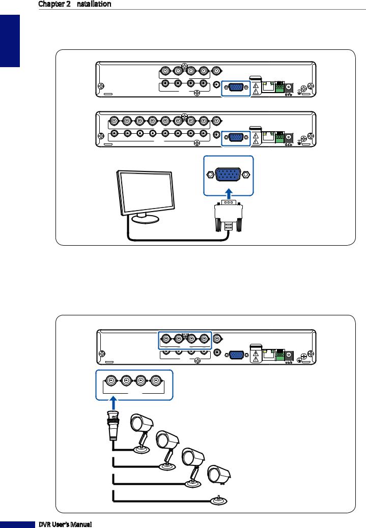
2.3.2 VGA Connection
Connect the video output of the DVR to the monitor via VGA connector as shown.
4-Channel DVR
|
|
|
|
CH4 |
CH3VIDEO IN CH2 |
CH1 |
VIDEO OUT |
CAUTION |
A B G |
||
|
|
|
|
|
|
|
|
|
RISK |
OF ELECTRIC SHOCK |
|
|
|
|
|
|
|
|
|
|
DO NOT OPEN |
||
|
|
|
|
AIN4 |
AIN3 |
AIN2 |
AIN1 |
AUDIO OUT |
|
|
|
|
|
|
|
|
AUDIO IN |
|
VGA |
|
|
||
|
|
|
|
|
|
|
|
|
|||
|
|
|
|
|
|
|
|
|
NETWORK |
RS485 |
|
|
|
|
|
|
|
|
|
|
|
||
|
|
|
|
|
|
8-Channel DVR |
|
|
|
||
CH8 |
CH7 |
CH6 |
CH5VIDEO IN CH4 |
CH3 |
CH2 |
CH1 |
VIDEO OUT |
CAUTION |
A B G |
||
|
|
|
|
|
|
|
|
|
RISK |
OF ELECTRIC SHOCK |
|
|
|
|
|
|
|
|
|
|
DO NOT OPEN |
||
AIN8 |
AIN7 |
AIN6 |
AIN5 |
AIN4 |
AIN3 |
AIN2 |
AIN1 |
AUDIO OUT |
|
|
|
|
|
|
AUDIO IN |
|
|
|
VGA |
|
|
||
|
|
|
|
|
|
|
|
|
|||
|
|
|
|
|
|
|
|
|
NETWORK |
RS485 |
|
|
|
|
|
|
|
|
|
|
|
||
Monitor
VGA
 VGA cable
2.4 Connecting the Cameras
Connect the camera cable(s) to the video input of the DVR via BNC or RS-485 connection.
2.4.1 BNC Connection
Connect the camera cable(s) to the video input of the DVR via BNC connector as shown.
4-Channel DVR
CH4 |
CH3VIDEO IN CH2 |
CH1 |
VIDEO OUT |
CAUTION |
A B G |
||
|
|
|
|
|
RISK |
OF ELECTRIC SHOCK |
|
|
|
|
|
|
DO NOT OPEN |
||
AIN4 |
AIN3 |
AIN2 |
AIN1 |
AUDIO OUT |
|
|
|
|
AUDIO IN |
|
|
VGA |
|
|
|
|
|
|
|
|
|
||
|
|
|
|
|
NETWORK |
RS485 |
|
|
|
|
|
|
|
||
CH4 |
CH3 |
CH2 |
CH1 |
|
VIDEO IN |
|
|
BNC cable
 Camera
DVR User’s Manual
14
Chapter 2:
 Installation
8-Channel DVR
CH8 |
CH7 |
CH6 |
CH5VIDEO IN CH4 |
CH3 |
CH2 |
CH1 |
VIDEO OUT |
|
CAUTION |
A B G |
|
AIN8 |
AIN7 |
AIN6 |
AIN5 |
AIN4 |
AIN3 |
AIN2 |
AIN1 |
AUDIO OUT |
|
|
|
|
|
|
AUDIO IN |
|
|
|
VGA |
|
|
||
|
|
|
|
|
|
|
|
|
|||
|
|
|
|
|
|
|
|
|
|
NETWORK RS485 |
|
|
|
|
|
|
|
|
|
|
|
|
|
CH8 |
CH7 |
CH6 |
CH5 |
CH4 |
CH3 |
CH2 |
CH1 |
||
|
|
|
|
VIDEO IN |
|
|
|
|
|
|
|
|
|
|
|
|
|
||
BNC cable
Camera
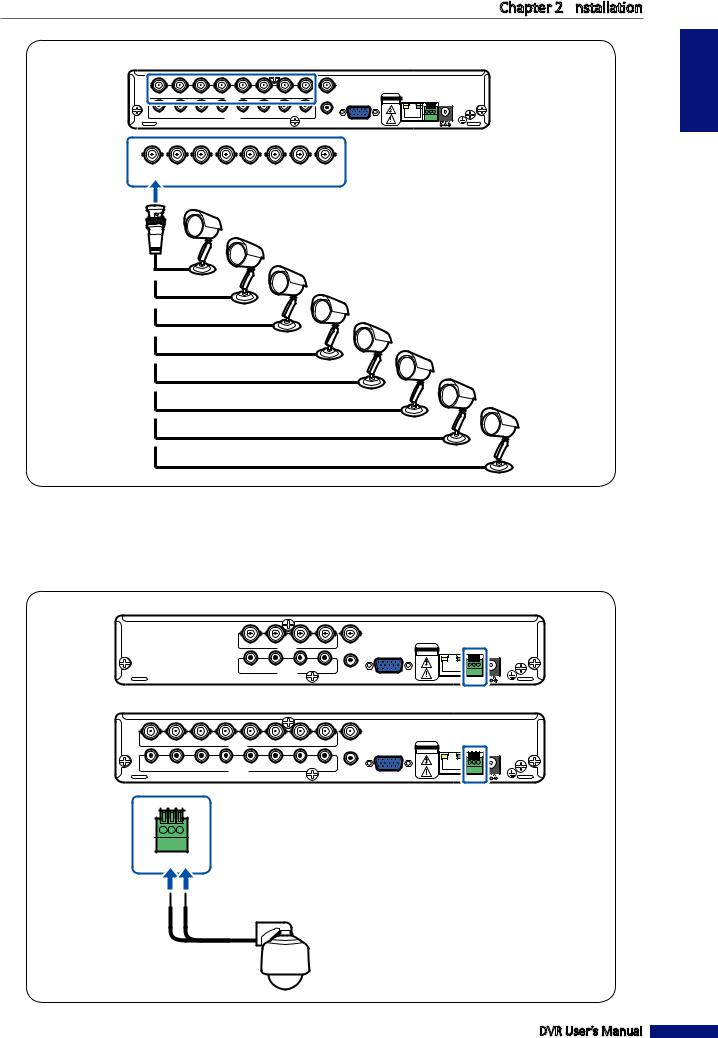
2.4.2 RS-485 Connection
If you are using a PTZ speed dome, connect the camera cable to the video input of the DVR via RS-485 connector as shown.
4-Channel DVR
|
|
|
|
CH4 |
CH3VIDEO IN CH2 |
CH1 |
VIDEO OUT |
CAUTION |
A B G |
||
|
|
|
|
|
|
|
|
|
RISK |
OF ELECTRIC SHOCK |
|
|
|
|
|
|
|
|
|
|
DO NOT OPEN |
||
|
|
|
|
AIN4 |
AIN3 |
AIN2 |
AIN1 |
AUDIO OUT |
|
|
|
|
|
|
|
|
AUDIO IN |
|
VGA |
|
|
||
|
|
|
|
|
|
|
|
|
|||
|
|
|
|
|
|
|
|
|
NETWORK |
RS485 |
|
|
|
|
|
|
|
|
|
|
|
||
|
|
|
|
|
|
8-Channel DVR |
|
|
|
||
CH8 |
CH7 |
CH6 |
CH5VIDEO IN CH4 |
CH3 |
CH2 |
CH1 |
VIDEO OUT |
CAUTION |
A B G |
||
|
|
|
|
|
|
|
|
|
RISK |
OF ELECTRIC SHOCK |
|
|
|
|
|
|
|
|
|
|
DO NOT OPEN |
||
AIN8 |
AIN7 |
AIN6 |
AIN5 |
AIN4 |
AIN3 |
AIN2 |
AIN1 |
AUDIO OUT |
|
|
|
|
|
|
AUDIO IN |
|
|
|
VGA |
|
|
||
|
|
|
|
|
|
|
|
|
|||
|
|
|
|
|
|
|
|
|
NETWORK |
RS485 |
|
|
|
|
|
|
|
|
|
|
|
||
A B G
RS485
Speed dome
ENGLISH
DVR User’s Manual
15
ENGLISH
Chapter 2:
 Installation
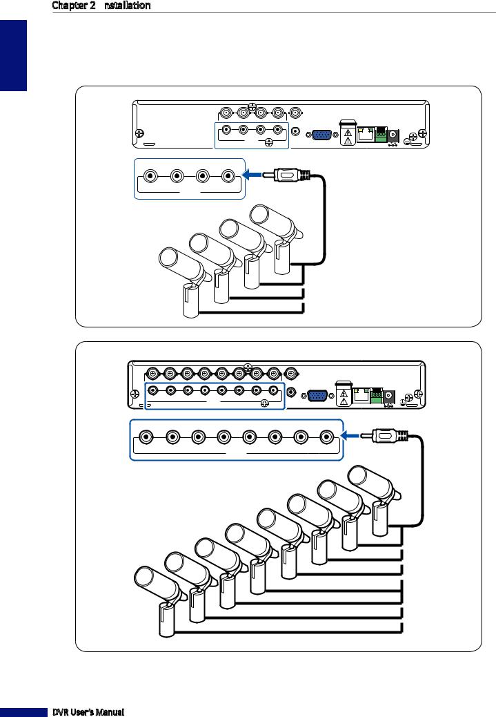
2.5 Connecting the Microphones
Microphones can be connected directly via RCA input connection.
Connect the microphone(s) using RCA cable connection as shown.
4-Channel DVR
CH4 |
CH3VIDEO IN CH2 |
CH1 |
VIDEO OUT |
CAUTION |
A B G |
||
|
|
|
|
|
RISK |
OF ELECTRIC SHOCK |
|
|
|
|
|
|
DO NOT OPEN |
||
AIN4 |
AIN3 |
AIN2 |
AIN1 |
AUDIO OUT |
|
|
|
|
AUDIO IN |
|
|
VGA |
|
|
|
|
|
|
|
|
|
||
|
|
|
|
|
NETWORK |
RS485 |
|
|
|
|
|
|
|
||
AIN4 |
AIN3 |
AIN2 |
AIN1 |
RCA audio cable |
|
AUDIO IN |
|
||
8-Channel DVR
CH8 |
CH7 |
CH6 |
CH5VIDEO IN CH4 |
CH3 |
CH2 |
CH1 |
VIDEO OUT |
CAUTION |
A B G |
||
|
|
|
|
|
|
|
|
|
RISK |
OF ELECTRIC SHOCK |
|
|
|
|
|
|
|
|
|
|
DO NOT OPEN |
||
AIN8 |
AIN7 |
AIN6 |
AIN5 |
AIN4 |
AIN3 |
AIN2 |
AIN1 |
AUDIO OUT |
|
|
|
|
|
|
AUDIO IN |
|
|
|
VGA |
|
|
||
|
|
|
|
|
|
|
|
|
|||
|
|
|
|
|
|
|
|
|
NETWORK |
RS485 |
|
|
|
|
|
|
|
|
|
|
|
||
AIN8 |
AIN7 |
AIN6 |
AIN5 |
AIN4 |
AIN3 |
AIN2 |
AIN1 |
RCA audio cable |
|
|
|
AUDIO IN |
|
|
|
|
|
Microphone
DVR User’s Manual
16
Chapter 2:
 Installation
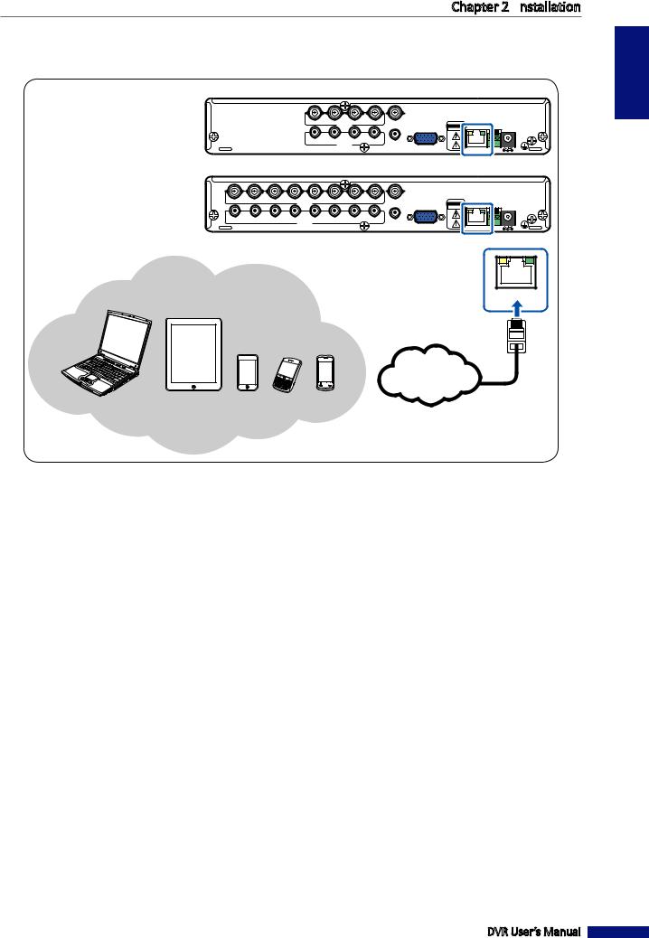
2.6 Connecting to Network
For remote monitoring, connect the DVR to the internet via wired network connection.
4-Channel DVR
|
|
|
|
CH4 |
CH3VIDEO IN CH2 |
CH1 |
VIDEO OUT |
|
CAUTION |
A B G |
|
|
|
|
|
|
|
|
|
|
|
ELECTRIC SHOCK |
|
|
|
|
|
|
|
|
|
|
|
RISK OFDO NOT OPEN |
|
|
|
|
|
AIN4 |
AIN3 |
AIN2 |
AIN1 |
AUDIO OUT |
|
|
|
|
|
|
|
|
AUDIO IN |
|
VGA |
|
|
||
|
|
|
|
|
|
|
|
|
|||
|
|
|
|
|
|
|
|
|
NETWORK |
RS485 |
|
|
|
|
|
|
|
|
|
|
|
||
|
|
|
|
|
|
8-Channel DVR |
|
|
|
||
CH8 |
CH7 |
CH6 |
CH5VIDEO IN CH4 |
CH3 |
CH2 |
CH1 |
VIDEO OUT |
|
CAUTION |
A B G |
|
|
|
|
|
|
|
|
|
|
|
ELECTRIC SHOCK |
|
|
|
|
|
|
|
|
|
|
|
RISK OFDO NOT OPEN |
|
AIN8 |
AIN7 |
AIN6 |
AIN5 |
AIN4 |
AIN3 |
AIN2 |
AIN1 |
AUDIO OUT |
|
|
|
|
|
|
AUDIO IN |
|
|
|
VGA |
|
|
||
|
|
|
|
|
|
|
|
|
|||
|
|
|
|
|
|
|
|
|
NETWORK |
RS485 |
|
|
|
|
|
|
|
|
|
|
|
||
NETWORK
Notebook/PC
Tablet PC
RJ-45 cable
Mobile Phones
 Internet
ENGLISH
1 Plug one end of the RJ-45 cable to the LAN port on the back of the DVR.
2 Plug the other end directly into a LAN port on a router or network switch.
After connecting, configure your DVR for network communication. See “4.2 Setting the Network” on page 33 for further details.
DVR User’s Manual
17
ENGLISH
Chapter 2:
 Installation
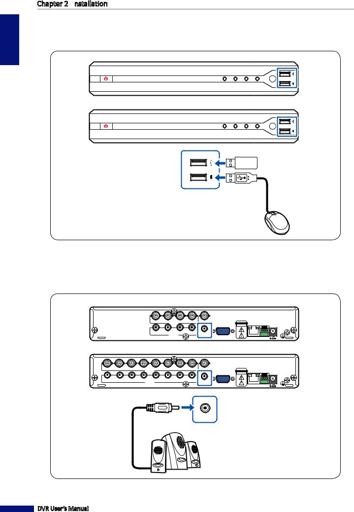
2.7 Connecting to Other Devices
You can connect other devices such as a mouse and a USB storage drive to the DVR. Connect them to the USB port on the back of the DVR.
4-Channel DVR
KGUARD
SECURITY
PWE |
LINK |
HDD |
REC |
4 Channel H.264 Digital Video Recorder
8-Channel DVR
KGUARD
SECURITY
PWE |
LINK |
HDD |
REC |
8 Channel H.264 Digital Video Recorder
2.8 Connecting to Speakers
You can connect speakers to the DVR via RCA connection.
Connect the speaker using RCA cable connection as shown.
4-Channel DVR
|
|
|
|
CH4 |
CH3VIDEO IN CH2 |
CH1 |
VIDEO OUT |
CAUTION |
A B G |
||
|
|
|
|
|
|
|
|
|
RISK |
OF ELECTRIC SHOCK |
|
|
|
|
|
|
|
|
|
|
DO NOT OPEN |
||
|
|
|
|
AIN4 |
AIN3 |
AIN2 |
AIN1 |
AUDIO OUT |
|
|
|
|
|
|
|
|
AUDIO IN |
|
VGA |
|
|
||
|
|
|
|
|
|
|
|
|
|||
|
|
|
|
|
|
|
|
|
NETWORK |
RS485 |
|
|
|
|
|
|
|
|
|
|
|
||
|
|
|
|
|
|
8-Channel DVR |
|
|
|
||
CH8 |
CH7 |
CH6 |
CH5VIDEO IN CH4 |
CH3 |
CH2 |
CH1 |
VIDEO OUT |
CAUTION |
A B G |
||
|
|
|
|
|
|
|
|
|
RISK |
OF ELECTRIC SHOCK |
|
|
|
|
|
|
|
|
|
|
DO NOT OPEN |
||
AIN8 |
AIN7 |
AIN6 |
AIN5 |
AIN4 |
AIN3 |
AIN2 |
AIN1 |
AUDIO OUT |
|
|
|
|
|
|
AUDIO IN |
|
|
|
VGA |
|
|
||
|
|
|
|
|
|
|
|
|
|||
|
|
|
|
|
|
|
|
|
NETWORK |
RS485 |
|
|
|
|
|
|
|
|
|
|
|
||
AUDIO OUT
DVR User’s Manual
18
Chapter 3: Getting Started
Chapter 3: Getting Started
3.1 Starting Up
1 Connect the power adapter to the DVR. See “2.2 Connecting the Power” on page 13 for further details.
2 Turn on the power switch on the front panel of the DVR. The DVR automatically powers on and displays the channels screen.
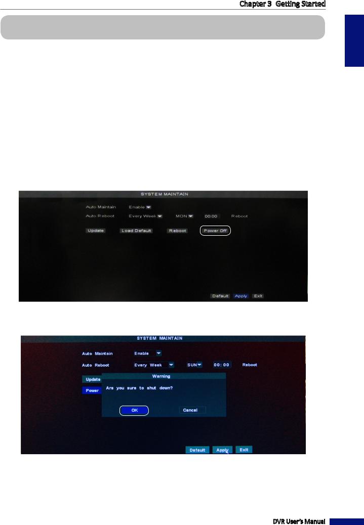
3.2 Shutting Down
To properly turn off the DVR power, do the following:
1 In the preview mode, right-click on the mouse to display the pop-up menu.
2 Select Main Menu > SYSTEM > MAINTAIN, and double-click Power off.
You can also access the main menu by pressing the MENU button on the remote control.
3 A warning message appears on the screen, select OK to turn off the power.
4 Wait until the “Now you can power off!” message appears on the screen.
5 Turn off the power switch on the front panel of the DVR and then unplug the power cord from the power outlet.
DVR User’s Manual
ENGLISH
19
ENGLISH
Chapter 3: Getting Started
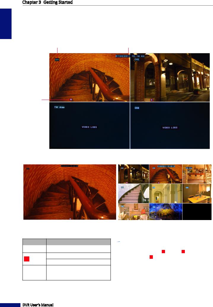
3.3 The Main Screen
3.3.1 Screen Icons
There are four types of recording indicator on the main screen of each channel.
Channel title (see page 30) |
Current date & time |
Recording indicator
4-channel display
1-channel display
Icon |
Description |
||
|
|
|
|
|
|
|
|
|
M |
Motion detector is activated. |
|
HHard disk drive memory is full. Cannot detect hard disk drive.
|
R |
|
Video recording is in progress. |
|
|
|
|
VIDEO LOSS |
Video loss. |
||
DVR User’s Manual
8-channel display
 Note:
Note:
•During recording mode, [ R ] icon or [ M ] icon appears
on the screen. If [ M ] icon is displayed on the screen, it indicates that motion detection is enabled.
•If the “VIDEO LOSS” appears on the screen, check the camera(s) connection.
20
Chapter 3: Getting Started
3.3.2 Virtual Keyboard
The virtual keyboard automatically appears on the screen if data entry is required.
There are two types of keyboard:
a. Full keyboard
Click to toggle the keyboard:
Click to delete a character.
Click to confirm the input.
b. Number keypad
Click to toggle the keyboard:
Click to delete a number.
Click to confirm the input.
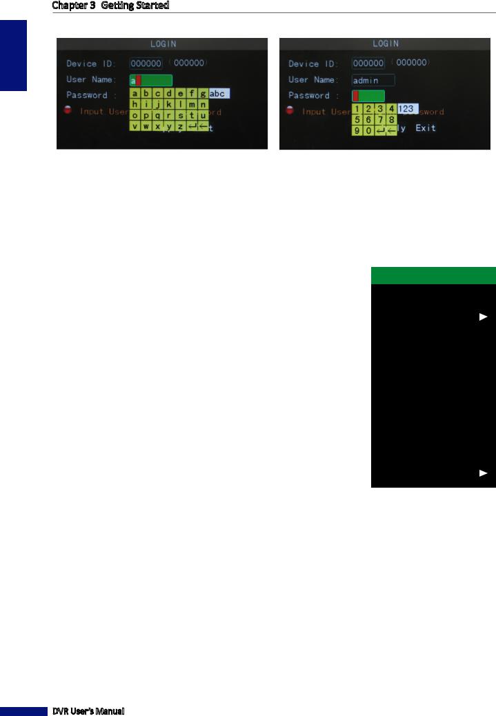
3.3.3 Locking the Screen
For system security, lock the screen to protect unauthorized OSD operation. 1 In the preview mode, right-click on the mouse to display the Pop-up menu.
2 Select Main Menu > SYSTEM > PASSWORD.
3 Set the Password Status to ON.
ON
4 Enter the user name and password. Then, click Apply.
5 Click OK.
6 To lock the screen, right-click to display the Pop-up menu and select Lock.
7 Once the lock function is activated, you need to enter the user name and password before entering the OSD menu.
DVR User’s Manual
ENGLISH
21
Chapter 3: Getting Started
A virtual keyboard automatically appears on the screen.
ENGLISH
Enter User Name |
Enter Password |
3.3.4 Pop-up Menu
With Pop-up menu, you can gain access to the frequently access features. You can access the Pop-up Menu by pressing
the right button of the mouse. The available Pop-up menu items vary depending on the current setting or operation.
•Main Menu:
Access the main menu and adjust all settings.
•Lock:
Lock access to enter OSD menu.
You need to enter the user name and password before entering the OSD menu.
•Multipicture:
Configure the window display setting. See page 25.
•Record Search
Search to playback recorded videos. See “4.3.1 Searching and Playing Videos” on page 36.
•Start Rotate:
Start rotate-display mode. See page 26.
•Start Cruise:
Start cruise of the PTZ camera. See page 28.
•PTZ:
Use the PTZ control. See page 27.
•Mute On/Off:
Enable/Disable mute feature. See page 29.
•Manual Record:
Start manual recording. See page 29.
•Stop Record
Stop recording manually. See page 29.
•PIP:
Configure the Picture-in-Picture (PIP) window display. See page 25.
Main Menu
Lock
Multipicture
Record Search
Start Rotate
Start Cruise
PTZ
Mute On
Manual Record
Stop Record
PIP
DVR User’s Manual
22
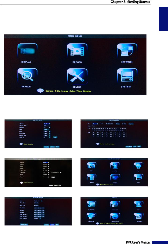
3.3.5 On Screen Display (OSD) menu
You can access the OSD menu by one of the following ways:
•Right-click on the mouse and select Main Menu.
•Press the MENU button on the remote control.
Submenu items:
DISPLAY |
SEARCH |
RECORD |
DEVICE |
NETWORK |
SYSTEM |
Chapter 3: Getting Started
ENGLISH
DVR User’s Manual
23

ENGLISH
Chapter 3: Getting Started
3.4 Screen Modes
3.4.1 Live View
By default, all channels are displayed on the screen in grid form.
To view the live image of any channel on full screen, simply double-click the left mouse button. Double-click the left mouse button again to return to the window-display of all cameras.
DVR User’s Manual
24
Chapter 3: Getting Started
3.4.2 Multi Picture Mode |
|
|
|
You can customize to view the channels on a 4-window or an 8-window display. |
|
|
|
Main Menu |
|
||
|
|
|
|
There are 3 multi picture mode options: |
Lock |
|
|
1 In the preview mode, right-click on the mouse to display the |
Multipicture |
CH01~08 |
|
Record Search |
CH01~04 |
||
Pop-up menu. |
Start Rotate |
CH05~08 |
|
|
|
|
|
2 Select Multipicture, then select an option: |
Start Cruise |
|
|
• |
CH 01-08 |
PTZ |
|
• |
CH 01-04 |
Mute On |
|
Manual Record |
|
||
• |
CH 05-08 |
|
|
Stop Record |
|
||
The selected channels will be displayed on the screen. |
PIP |
|
|
|
|
||
 Note:
Note:
Options to split windows vary depending on the DVR model. Split Windows option is not available when View Setup is enabled (see “4.5.3 Video and Audio Settings” on page 49).
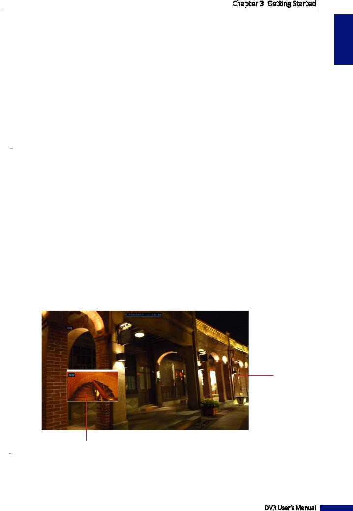
3.4.3 Picture-in-Picture (PIP) Mode
With Picture-in-Picture (PIP) mode, you can watch two more channels |
Main Menu |
|
to be simultaneously displayed on the first channel live preview. |
Lock |
|
1 In the preview mode, right-click on the mouse |
Multipicture |
|
Record Search |
|
|
to display the Pop-up menu. |
|
|
Start Rotate |
|
|
2 Select PIP > 1 X1 or 1 X2. |
|
|
Start Cruise |
|
|
An additional mini-window appears on the main screen display. |
PTZ |
|
3 To move the mini-windows around your main screen, |
Mute On |
|
Manual Record |
|
|
click and drag it to a new position. |
Stop Record |
|
|
|
|
|
PIP |
1X1 |
For example: PIP 1 X1 mode |
|
1X2 |
|
|
First channel
Second channel
 Note:
Note:
If you select 1 X2, two mini-window frames appear on the main screen display. This function only works if there are more than two cameras connected to the DVR.
DVR User’s Manual
ENGLISH
25
ENGLISH
Chapter 3: Getting Started
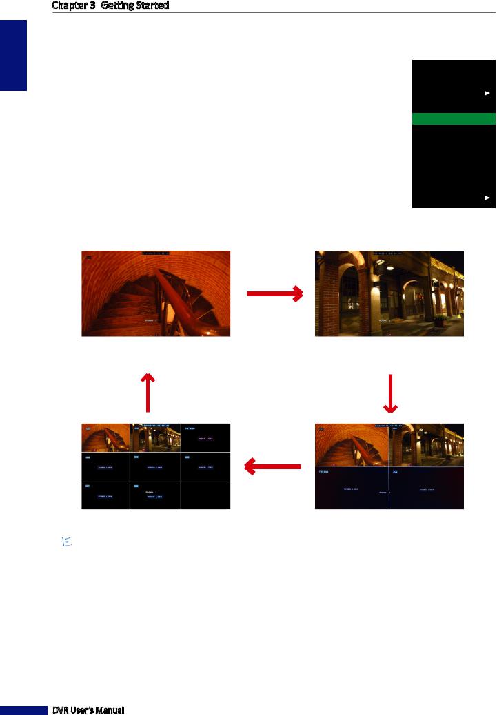
3.4.4 Auto Switch View
With this function, the system will automatically switch the channel display.
To enable auto switch view:
1 In the preview mode, right-click on the mouse to display the Pop-up menu.
2Select Start Rotate.
The rotating display playback starts. By default, each display switches at 5 seconds interval. You can change the switch interval in VIDEO menu (see “Setting the Video Output” on page 49).
Main Menu
Lock
Multipicture
Record Search
Start Rotate
Start Cruise
PTZ
Mute On
Manual Record
Stop Record
PIP
An example of the screen display rotation as follow (8-channel DVR with 2 available channels):
Full screen |
Full screen |
(First channel) |
(Second channel) |
8-window display |
4-window display |
 Note:
Note:
The displayed screens vary depending on the available channels.
To disable auto switch view, click on the screen.
DVR User’s Manual
26
Loading...