


 Loading...
DVR
USER MANUAL
DVR with Cloud Technology
Easy Link PRO Series ( EL422/EL822/EL1622)
Default user name: admin
Default password: 123456

ENGLISH
Easy Link PRO Series: Preface
About this Manual
The material in this document is for information purpose and is subject to change without prior notice. We made every effort to ensure that this user’s manual is accurate and complete. However, no liability is assumed for any errors and omissions that may have occurred.
FCC Compliance Statement
This equipment has been tested and found to comply with the limits for a Class B digital device, pursuant to Part 15 of the FCC Rules. These limits are designed to provide reasonable protection against harmful interference in a residential installation. This equipment generates uses and can radiate radio frequency energy and, if not installed and used in accordance with the instructions, may cause harmful interference to radio communications. However, there is no guarantee that interference will not occur in a particular installation. If this equipment does cause harmful interference to radio or television reception, which can be determined by turning the equipment off and on, the user is encouraged to try to correct the interference by one or more of the following measures:
•Reorient or relocate the receiving antenna.
•Increase the separation between the product and receiver.
•Connect the product into an outlet on a circuit different from that to which the receiver is connected.
•Consult the dealer or an experienced radio/TV technician for help.
Declaration of Conformity
This device complies with part 15 of the FCC Rules. Operation is subject to the following two conditions:
1.This device may not cause harmful interference.
2.This device must accept any interference received, including interference that may cause undesired operation.
Copyright
Limitation of Liability
•This publication is provided “AS IS” without warranty of any kind, either expressed or implied, including but not limited to, the implied warranties of merchantability, fitness for any particular purpose, or noninfringement of a third party’s rights.
•This publication may include technical inaccuracies or typographical errors. Changes may be made to the information herein, at any time, for publication improvements and/or of the corresponding device(s).
Disclaimer of Warranty
In no event shall the supplier be liable to any party or any person, except for replacement or reasonable maintenance of the product, for the cases, including but not limited to the following:
•Any damage or loss, including but without limitation, direct or indirect, special, consequential or exemplary, arising out of or relating to the device;
•Personal injury or any damage caused by inapppropriate use or negligent operation of the user;
•Unauthorized disassemble, repair or modification of the device by the user;
•Any problem, consequential inconvenience, or loss or damage, arising out of combining the system with the devices of a third party;
•Any claim or action for damages, brought by any person or organization being a photogenic subject, due to violation of privacy with the result of pictures from a surveillance camera, including saved data, for some reason, becomes public or is used for the purpose other than for surveillance.
DVR User’s Manual
2
|
Easy Link PRO Series: Preface |
Safety Information |
|
Warning |
Caution |
This is the symbol for indicating any potential hazard, |
The lighting flash with an arrow head symbol, in an |
risk or condition requiring special attention. |
equilateral triangle, is intended to alert the user. |
The user needs to refer to the important operating |
There is dangerous “voltage” presence near by the |
and maintenance or servicing instructions. |
product’s enclosure which may be risk of person. |
Safety Precautions
•Do not touch live electrical parts.
Electric shock can be avoided. Follow the recommended practices listed below. Faulty installation, improper grounding, and incorrect operation and maintenance of electrical equipment are always sources of danger.
•Do not try to install equipment outdoor, during strong wind and rain.
•Do not install or remove equipment outdoor, when raining.
•Do not try to install or operate any equipment, during a thunderstorm.
•Always ground all electrical equipment and the work platform.
Prevent accidental electrical shocks. Connect power source, control cabinets, and work platform to an approved electrical ground.
•Always use the correct cable size.
Sustained overloading will cause cable failure and result in possible electrical shock or fire hazard. Work cable should be the same rating as the factory.
•Always keep cables and connectors in good condition.
Improper or worn electrical connections can cause short circuits and can increase the chance of an electrical shock. Do not use worn, damaged, or bare cables.
•Always avoid open-circuit voltage.
The added voltages increase the severity of electric shock hazard.
•Always wear insulated gloves while you adjust equipment.
Electric power should be turned off and insulated gloves should be worn when making any equipment adjustment to assure shock protection.
•Always wear protective clothing such as long sleeve shirts while you are installing or removing equipment.
•Always wear high, snug fitting shoes.
•Always wear clean clothes without grease or oil.
•Protect neighboring workers from exposure to arc radiation.
•Always wear long trousers or jeans while you are installing or removing equipment.
•Always wear safety helmet or hard hat and safety shoes before work.
•Always keep the equipment in dry places.
•Always wear safety harnesses/belt while you work in high places.
•Always wear dry clothing and avoid moisture and water.
•Always wear Public Safety Vest, while you work at night.
•Make sure all electrical connections are tight, clean, and dry.
•Make sure that you are well insulated to eliminate electric static charge.
•Always wear dry gloves, rubber-soled shoes, or stand on a dry board or platform.
•Always follow recognized safety standards.
•Always wear correct eye, ear, and body protection.
•Always have second person on-site, while you work in dark, poor ventilation, or high places.
•Make sure that you are well protected against arc flashes, mechanical injury, or other mishaps.
•Make sure that the polarity of wire is correct before installing equipment.
•Always handle equipment with care.
•Do not block the ventilation of equipment.
•Do not put the magnetic parts around the equipment.
•Do not put the objects on top of the equipment.
DVR User’s Manual
ENGLISH
3

ENGLISH
Easy Link PRO Series: Contents |
|
Contents |
|
About this Manual..................................................................................................................... |
2 |
FCC Compliance Statement....................................................................................................... |
2 |
Copyright................................................................................................................................... |
2 |
Safety Information..................................................................................................................... |
3 |
Quick Setup Guide.............................................................................................. |
6 |
Step 1: Unpack Your DVR.......................................................................................................... |
6 |
4-Channel / 8-Channel DVR..................................................................................... |
6 |
16-Channel DVR....................................................................................................... |
7 |
Step 2: Install the Hard Disk Drive (HDD).................................................................................. |
8 |
Step 3: Make the Connections................................................................................................... |
9 |
Front Panel........................................................................................................................ |
9 |
Rear Panel....................................................................................................................... |
10 |
Perform the connections as shown on the diagrams.............................................................. |
12 |
Step 4: Power ON the DVR...................................................................................................... |
18 |
Step 5: Go through the Items in Startup Wizard..................................................................... |
19 |
Step 6: Make Sure the Camera(s) are Functioning.................................................................. |
24 |
4-Channel DVR................................................................................................................ |
24 |
8-Channel DVR................................................................................................................ |
25 |
16-Channel DVR.............................................................................................................. |
25 |
Understanding the Live Viewing Screen............................................................. |
26 |
Pop-Up Menu on Live Viewing Screen..................................................................................... |
30 |
Basic DVR Operation......................................................................................... |
34 |
Using the Supplied USB Mouse............................................................................................... |
34 |
Virtual Keyboard...................................................................................................................... |
34 |
Locking the Screen.................................................................................................................. |
34 |
Using the Supplied Remote Control........................................................................................ |
35 |
Rebooting/Shutting Down the DVR......................................................................................... |
36 |
Accessibility Features........................................................................................ |
37 |
Downloading KViewQR App.................................................................................................... |
37 |
Using Cloud Storage................................................................................................................ |
43 |
Dropbox.......................................................................................................................... |
43 |
How to Create a Dropbox Account........................................................................ |
43 |
How to Configure the Cloud Storage Settings for Dropbox................................... |
44 |
Advanced E-mail Setup.......................................................................................... |
46 |
Activate Cloud........................................................................................................ |
47 |
Google Drive................................................................................................................... |
49 |
How to Create a Google Account........................................................................... |
49 |
How to Configure the Cloud Storage Settings for Google Drive............................ |
50 |
Check the Photos/Videos on Google Drive............................................................ |
52 |
Operating the DVR............................................................................................ |
53 |
Main Menu.............................................................................................................................. |
53 |
Display: Live............................................................................................................................. |
55 |
Display: Output........................................................................................................................ |
56 |
DVR User’s Manual |
|
4

|
Easy Link PRO Series: Contents |
Display: Privacy Zone............................................................................................................... |
58 |
Record: REC Para..................................................................................................................... |
59 |
Record: Schedule..................................................................................................................... |
60 |
Record: Record Setup.............................................................................................................. |
61 |
Search: Record Search............................................................................................................. |
62 |
Playback Screen.............................................................................................................. |
64 |
Trimming Videos............................................................................................................. |
65 |
Search: Event Search............................................................................................................... |
67 |
Search: Log.............................................................................................................................. |
68 |
Network: Network................................................................................................................... |
69 |
Network: Remote Stream........................................................................................................ |
71 |
Network: Email........................................................................................................................ |
72 |
Network: DDNS....................................................................................................................... |
73 |
Alarm: Motion......................................................................................................................... |
76 |
About Motion Detection................................................................................................. |
76 |
Set Motion Detection Area............................................................................................. |
76 |
Other Alarm Settings (16-Channel only)......................................................................... |
77 |
Device: HDD............................................................................................................................. |
78 |
Device: PTZ.............................................................................................................................. |
79 |
Device: Cloud Storage.............................................................................................................. |
80 |
Google Drive................................................................................................................... |
80 |
Dropbox.......................................................................................................................... |
82 |
System: General....................................................................................................................... |
85 |
System: Users.......................................................................................................................... |
86 |
System: Info............................................................................................................................. |
87 |
Advanced: Maintain................................................................................................................ |
88 |
Remote Access Via Web Client.......................................................................... |
93 |
Logging In ............................................................................................................................... |
93 |
Interface Overview.................................................................................................................. |
94 |
Live Viewing............................................................................................................................. |
95 |
Switching Screen Modes......................................................................................................... |
96 |
Viewing or Hiding Channels............................................................................................ |
96 |
Recording Channels Manually............................................................................... |
96 |
Taking Snapshots............................................................................................................. |
97 |
Using PTZ Controls................................................................................................................... |
98 |
About the Main Menu............................................................................................................. |
99 |
Local Settings................................................................................................................ |
100 |
Logging Off.................................................................................................................... |
100 |
Appendix......................................................................................................... |
101 |
Troubleshooting.................................................................................................................... |
101 |
Specifications......................................................................................................................... |
103 |
ENGLISH
DVR User’s Manual
5

ENGLISH
Easy Link PRO Series: Quick Setup Guide
Quick Setup Guide
Thank you for purchasing the Easy Link PRO Series Digital Video Recorder (DVR). This DVR is developed by KGuard Security and compromises the advanced H.264 video encoding and decoding technology for delivering high performance, and ultimate reliability.
This DVR is able to monitor or record four, eight, or sixteen (depending on your model) channels simultaneously. You can define the recording mode for each channel independently or apply the configured settings for some or all of the cameras.
As to the accessibility options, the DVR allows you to see live view from the cameras via smart phone/tablet or PC. For an easy access and backup purposes, you can configure the DVR to send photos or videos from the device directly to the cloud storage (Dropbox or Google Drive).
Step 1: Unpack Your DVR
Please take a moment to check if all the necessary items are included in the package. If anything is missing or damaged, please contact your retailer immediately.
4-Channel / 8-Channel DVR
• |
DVR |
• |
Mouse |
• |
12V/2A power adapter |
• |
Remote control |
||||
|
|
|
|
|
|
|
3 |
6 |
9 |
MENU |
MUTE |
|
|
|
|
|
|
|
2 |
5 |
8 |
0 |
SEL |
|
|
|
|
|
|
|
1 |
4 |
7 |
ALL |
AUDIO/ SEARCH |
• |
HDMI cable |
• |
RJ45 cable |
• |
Battery |
• |
3.5”/2.5” HDD Screws |
||||
• Quick Start Guide |
• CD |
||
|
|
|
|
Quick |
|
|
|
|
|
|
|
Guide |
|
|
|
|
|
|
|
DVR User’s Manual
6

Easy Link PRO Series: Quick Setup Guide
16-Channel DVR
• |
DVR |
• |
Mouse |
• |
12V/2A power adapter |
• |
Remote control |
|
|
||||||
|
|
|
|
|
|
|
3 |
6 |
9 |
0 |
|
ENTER |
MENU/ESCPIP MUTE FWD STOP REW SLOW F+Z+ I+ PTZ |
FOCUSZOOMIRIS |
LOCK |
|
|
|
|
|
|
|
2X2 |
3X3 |
4X4 |
AUTO |
|
Z |
|||
|
|
|
|
|
|
|
2 |
5 |
8 |
DISPLAY |
MODE |
|
PLAY |
|
I |
|
|
|
|
|
|
|
|
|
|
|
|
|
|
_ |
|
|
|
|
|
|
|
|
1 |
4 |
7 |
|
|
|
|
|
F_ |
|
|
|
|
|
|
|
|
|
|
|
|
|
|
|
_ |
• |
HDMI cable |
• |
RJ45 cable |
• |
Battery |
• |
3.5”/2.5” HDD Screws |
||||||||
• Quick Start Guide |
• CD |
||
|
|
|
|
Quick |
|
|
|
|
|
|
|
Guide |
|
|
|
|
|
|
|
ENGLISH
DVR User’s Manual
7

ENGLISH
Easy Link PRO Series: Quick Setup Guide
Step 2: Install the Hard Disk Drive (HDD)
The reason you need to install an HDD on the DVR is to be able to save video footages from the security camera(s).
This DVR supports one 3.5” or 2.5” SATA HDD.
CAUTION: DO NOT install or remove the hard disk drive while the device power is turned ON.
To install the HDD, follow the instructions below.
NOTE:
•Depending on the model you purchased, the actual product may slightly differ from the images below.
•The illustrations below show an 8-channel DVR, same procedures apply to a 4-channel and 16-channel DVR.
1.Remove the cover
Loosen the screws as shown. |
Push back then lift up the cover to remove it. |
|
|
|
|
2. Install and secure the HDD |
|
|
|
Connect the data and power cables to the HDD and |
Align the HDD on the holes on the DVR case and |
||
place the HDD on the DVR case. |
|||
secure the HDD using the four (4) supplied screws. |
|||
|
|||
|
|
|
|
3. Replace the cover
Attach the cover and the screws back in place.
DVR User’s Manual
8
Easy Link PRO Series: Quick Setup Guide
Step 3: Make the Connections
In order to make the connections, you need to know the connection ports and the meaning of the control LEDs. Please take a moment to review the front and rear panel.
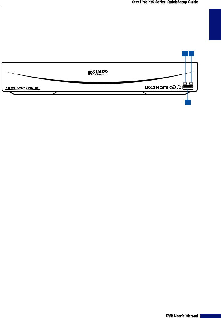
Front Panel
NOTE: The following example illustrates the front panel of the 8-channel DVR.
1 2
3
1)HDD Indicator: Flashing red when the HDD is being accessed (read/write operation).
2)Power Indicator: Lights green to indicate the power is turned on.
3)USB 2.0 Port: Connects to a USB mouse, flash disk, and other external storage drive.
DVR User’s Manual
ENGLISH
9
ENGLISH
Easy Link PRO Series: Quick Setup Guide
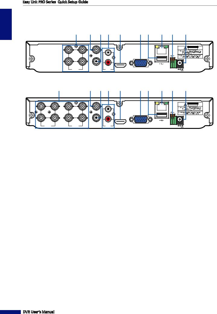
Rear Panel
4-Channel DVR
1 |
|
2 |
|
3 |
|
4 |
|
5 |
|
6 |
|
7 |
|
8 |
|
9 |
|
10 |
|
|
VIDEO |
|
|
|
|
|
OUTPUT |
|
|
CAUTION |
|
|
|
|
|
RISK OF ELECTRIC SHOCK |
|
|
|
|
|
DO NOT OPEN |
|
|
|
|
|
LAN |
3 |
1 |
1 |
|
|
|
|
|
|
|
|
|
4 |
2 |
2 AUDIO |
|
|
|
VIDEO |
AUDIO |
HDMI |
VGA |
RS-485 12V |
|
INPUT |
OUTPUT |
INPUT |
8-Channel DVR
1 |
|
2 |
|
3 |
|
4 |
|
5 |
|
6 |
|
7 |
|
8 |
|
9 |
|
10 |
|
|
|
|
VIDEO |
|
|
|
|
|
|
|
OUTPUT |
|
|
CAUTION |
|
|
|
|
|
|
|
RISK OF ELECTRIC SHOCK |
|
|
|
|
|
|
|
DO NOT OPEN |
|
|
|
|
|
|
|
LAN |
7 |
5 |
3 |
1 |
1 |
|
|
|
|
|
|
|
|
|
|
|
8 |
6 |
4 |
2 |
2 AUDIO |
|
|
|
VIDEO |
|
VIDEO |
AUDIO |
HDMI |
VGA |
RS-485 12V |
|
INPUT |
|
INPUT |
OUTPUT |
INPUT |
1)Video input:
•4-Channel DVR: Connects to a maximum of 4 cameras (BNC).
•8-Channel DVR: Connects to a maximum of 8 cameras (BNC).
2)Video output: Connects to a monitor/TV via BNC.
3)Audio output: Connects to an audio output device (for example, speaker) via RCA.
4)Audio input: Connects to a maximum of 2 microphones and/or audio-supported camera (not included) via RCA.
5)HDMI output: Connects to a monitor/TV via HDMI.
6)VGA output: Connects to a VGA monitor.
7)USB port: Connects to a USB mouse, flash disk, and other external storage drive.
8)LAN: Connects to a router via RJ-45.
9)RS-485: Connects to a Speed dome camera via RS-485.
10)Power: Connects to the power adapter.
DVR User’s Manual
10
Easy Link PRO Series: Quick Setup Guide
16-Channel DVR
|
|
|
1 |
|
|
|
2 |
3 |
4 |
|
6 |
9 |
10 |
12 |
ENGLISH |
|
|
|
|
|
|
|
VIDEO OUTPUT |
|
|
|
|
|
|
||
|
|
|
|
|
|
|
|
|
|
|
|
|
|
|
|
15 |
13 |
11 |
9 |
7 |
5 |
3 |
1 |
|
3 |
1 |
VGA |
|
G 1 2 3 4 G 5 6 7 8 |
IR-EXT |
|
|
RS-485 ALARM |
|
|
||||||||||||
|
|
|
|
|
|
|
|
|
|
|
|
|
SENSOR |
|
|
16 |
14 |
12 |
10 |
8 |
6 |
4 |
2 |
|
4 |
2 |
|
|
|
|
|
|
|
|
|
|
|
|
|
||||||||
|
|
|
VIDEO INPUT |
|
|
|
AUDIO |
|
AUDIO |
|
HDMI |
LAN |
12V |
|
|
|
|
|
|
|
|
|
OUTPUT |
|
INPUT |
|
|
|
|||
5 |
|
8 |
|
7 |
|
11 |
|
13 |
1)Video input: Connects to a maximum of 16 cameras (BNC).
2)Video output: Connects to a monitor/TV via BNC.
3)Audio output: Connects to an audio output device (for example, speaker) via RCA.
4)Audio input: Connects to a maximum of 4 microphones and/or audio-supported camera (not included) via RCA.
5)HDMI output: Connects to a monitor/TV via HDMI.
6)VGA output: Connects to a VGA monitor.
7)USB port: Connects to a USB mouse, flash disk, and other external storage drives.
8)LAN port: Connects to a router via RJ-45.
9)RS-485 port: Connects to a Speed dome camera via RS-485.
10)Alarm and Sensor I/O block: Connect to external Sensors and Alarm devices.
11)Power: Connects to the power adapter.
12)Infrared extender port: If the distance between the remote control and the DVR is too far, you need to install an IR extender into the IR extender port (not supplied).
13)Power switch: Switch to turn the DVR on / off.
DVR User’s Manual
11
ENGLISH
Easy Link PRO Series: Quick Setup Guide
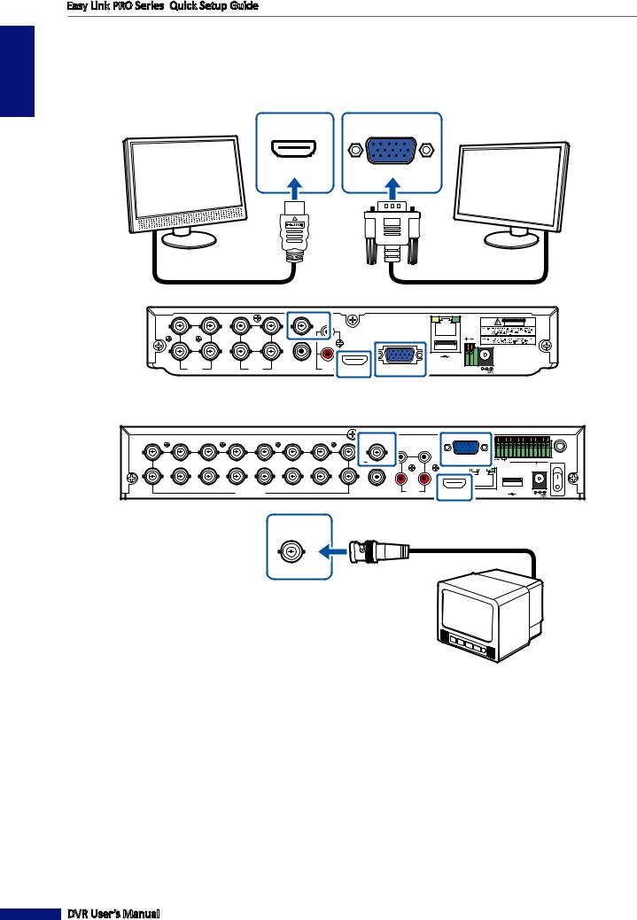
Perform the connections as shown on the diagrams.
1. Connect the monitor/TV to the DVR via HDMI (recommended), VGA, or BNC connector.
If your monitor/TV supports
HDMI, connect it to the
HDMI output on the DVR.
HDMI
VGA
Or connect the video output of the DVR to the monitor via VGA connector.
|
|
|
|
|
|
4-Channel DVR / 8-Channel DVR |
|
|
|
|
|
VIDEO |
|
|
|
|
|
|
|
OUTPUT |
|
|
CAUTION |
|
|
|
|
|
|
|
RISK OF ELECTRIC SHOCK |
|
|
|
|
|
|
|
DO NOT OPEN |
|
|
|
|
|
|
|
LAN |
7 |
5 |
3 |
1 |
1 |
|
|
|
|
|
|
|
|
|
|
|
8 |
6 |
4 |
2 |
2 AUDIO |
|
|
|
VIDEO |
|
VIDEO |
AUDIO |
HDMI |
VGA |
RS-485 12V |
|
INPUT |
|
INPUT |
OUTPUT |
INPUT |
|||
16-Channel DVR
|
|
|
|
|
|
|
VIDEO OUTPUT |
|
|
|
|
|
|
15 |
13 |
11 |
9 |
7 |
5 |
3 |
1 |
3 |
1 |
VGA |
|
|
IR-EXT |
RS-485 ALARM G |
1 |
2 3 4 G 5 6 7 8 |
|||||||||||
|
|
|
|
|
|
|
|
|
|
|
|
|
SENSOR |
16 |
14 |
12 |
10 |
8 |
6 |
4 |
2 |
4 |
2 |
|
|
|
|
|
|
|
|
|
|
||||||||
|
|
|
VIDEO INPUT |
|
|
|
AUDIO |
AUDIO |
|
HDMI |
LAN |
|
12V |
|
|
|
|
|
|
|
OUTPUT |
INPUT |
|
|
VIDEO
OUTPUT
Or connect the video output of the DVR to the monitor via BNC connector.
DVR User’s Manual
12

Easy Link PRO Series: Quick Setup Guide
2. Connect the cameras to the DVR.
|
|
|
|
4-Channel DVR / 8-Channel DVR |
|
|
|
VIDEO |
|
|
|
|
OUTPUT |
CAUTION |
|
|
|
|
RISK OF ELECTRIC SHOCK |
|
|
|
|
DO NOT OPEN |
|
|
|
|
LAN |
7 |
5 |
3 |
1 |
|
|
|
|
1 |
|
8 |
6 |
4 |
2 |
2 AUDIO |
|
|
|
VIDEO |
|
VIDEO |
AUDIO |
HDMI |
VGA |
RS-485 12V |
|
INPUT |
|
INPUT |
OUTPUT |
INPUT |
|
|
|
|
|
|
|
VIDEO OUTPUT |
|
|
|
|
|
15 |
13 |
11 |
9 |
7 |
5 |
3 |
1 |
3 |
1 |
VGA |
|
IR-EXT |
RS-485 ALARM |
G 1 2 3 4 G 5 6 7 8 |
|||||||||||
|
|
|
|
|
|
|
|
|
|
|
|
SENSOR |
16 |
14 |
12 |
10 |
8 |
6 |
4 |
2 |
4 |
2 |
|
|
|
|
|
|
|
|
||||||||
|
|
|
VIDEO INPUT |
|
|
|
AUDIO |
AUDIO |
|
HDMI |
LAN |
12V |
|
|
|
|
|
|
|
OUTPUT |
INPUT |
|
|
|
|
|
|
|
|
16-Channel DVR |
|
15 |
13 |
11 |
9 |
7 |
5 |
3 |
1 |
|
|
|
|
|
|
|
|
RS-485 ALARM |
G 1 2 3 4 G 5 6 7 8 |
|
|
|
|
|
|
|
|
SENSOR |
16 |
14 |
12 |
10 |
8 |
6 |
4 |
2 |
|
|
|
|
VIDEO INPUT |
|
|
|
|
|
If you are using a PTZ speed dome, connect the camera cable to the video input of the DVR via RS-485 connector.
ENGLISH
Connect the BNC plug of the camera’s extension cable to the Video input connector on the rear of the DVR.
DVR User’s Manual
13

ENGLISH
Easy Link PRO Series: Quick Setup Guide
3. Connect a USB mouse to the USB port on the DVR.
4-Channel DVR / 8-Channel DVR
|
|
|
|
VIDEO |
|
|
|
|
|
|
|
OUTPUT |
|
|
CAUTION |
|
|
|
|
|
|
|
RISK OF ELECTRIC SHOCK |
|
|
|
|
|
|
|
DO NOT OPEN |
|
|
|
|
|
|
|
LAN |
7 |
5 |
3 |
1 |
1 |
|
|
|
|
|
|
|
|
|
|
|
8 |
6 |
4 |
2 |
2 AUDIO |
|
|
|
VIDEO |
|
VIDEO |
AUDIO |
HDMI |
VGA |
RS-485 12V |
|
INPUT |
|
INPUT |
OUTPUT |
INPUT |
16-Channel DVR
|
|
|
|
|
|
|
VIDEO OUTPUT |
|
|
|
|
|
15 |
13 |
11 |
9 |
7 |
5 |
3 |
1 |
3 |
1 |
VGA |
|
IR-EXT |
RS-485 ALARM |
G 1 2 3 4 G 5 6 7 8 |
|||||||||||
|
|
|
|
|
|
|
|
|
|
|
|
SENSOR |
16 |
14 |
12 |
10 |
8 |
6 |
4 |
2 |
4 |
2 |
|
|
|
|
|
|
|
|
||||||||
|
|
|
VIDEO INPUT |
|
|
|
AUDIO |
AUDIO |
|
HDMI |
LAN |
12V |
|
|
|
|
|
|
|
OUTPUT |
INPUT |
|
 You need the USB mouse to go through the initial setup menus once the DVR is powered on.
DVR User’s Manual
14
Easy Link PRO Series: Quick Setup Guide
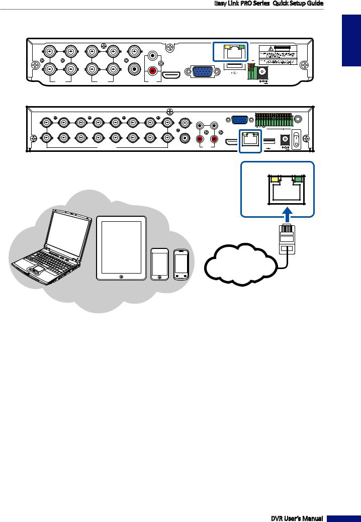
4. Connect the DVR to the Internet via wired network connection (optional).
|
|
|
|
|
|
|
4-Channel DVR / 8-Channel DVR |
|
|
|
|
VIDEO |
|
|
|
|
|
|
|
OUTPUT |
|
|
CAUTION |
|
|
|
|
|
|
|
RISK OF ELECTRIC SHOCK |
|
|
|
|
|
|
|
DO NOT OPEN |
|
|
|
|
|
|
|
LAN |
7 |
5 |
3 |
1 |
1 |
|
|
|
|
|
|
|
|
|
|
|
8 |
6 |
4 |
2 |
2 AUDIO |
|
|
|
VIDEO |
|
VIDEO |
AUDIO |
HDMI |
VGA |
RS-485 12V |
|
INPUT |
|
INPUT |
OUTPUT |
INPUT |
16-Channel DVR
|
|
|
|
|
|
|
VIDEO OUTPUT |
|
|
|
|
|
|
|
15 |
13 |
11 |
9 |
7 |
5 |
3 |
1 |
3 |
1 |
VGA |
|
|
|
IR-EXT |
RS-485 ALARM G |
1 |
2 |
3 4 G 5 6 7 8 |
|||||||||||
|
|
|
|
|
|
|
|
|
|
|
|
|
|
SENSOR |
16 |
14 |
12 |
10 |
8 |
6 |
4 |
2 |
4 |
2 |
|
|
|
|
|
|
|
|
|
|
|
|
||||||||
|
|
|
VIDEO INPUT |
|
|
|
AUDIO |
AUDIO |
|
HDMI |
LAN |
|
|
12V |
|
|
|
|
|
|
|
OUTPUT |
INPUT |
|
|
|
|
The network connection is |
|
|
necessary for accessing the DVR |
|
|
remotely via smart phone/tablet/ |
|
|
PC or for saving images/videos |
LAN |
|
to the cloud storage (Dropbox or |
|
|
|
|
Notebook/PC |
Google Drive). |
|
|
Tablet PC |
|
|
|
RJ-45 cable |
|
Smart Phones |
|
 Internet
Connect one end of the supplied RJ-45 cable to the router and the other end to the
LAN connector on the rear of the DVR.
ENGLISH
DVR User’s Manual
15

ENGLISH
Easy Link PRO Series: Quick Setup Guide
5. Connect the microphones and speakers via RCA connection (optional).
|
|
|
|
|
|
|
4-Channel DVR / 8-Channel DVR |
|
|
|
|
VIDEO |
|
|
|
|
|
|
|
OUTPUT |
|
|
CAUTION |
|
|
|
|
|
|
|
RISK OF ELECTRIC SHOCK |
|
|
|
|
|
|
|
DO NOT OPEN |
|
|
|
|
|
|
|
LAN |
7 |
5 |
3 |
1 |
1 |
|
|
|
|
|
|
|
|
|
|
|
8 |
6 |
4 |
2 |
2 AUDIO |
|
|
|
VIDEO |
|
VIDEO |
AUDIO |
HDMI |
VGA |
RS-485 12V |
|
INPUT |
|
INPUT |
OUTPUT |
INPUT |
16-Channel DVR
|
|
|
|
|
|
|
VIDEO OUTPUT |
|
|
|
|
|
15 |
13 |
11 |
9 |
7 |
5 |
3 |
1 |
3 |
1 |
VGA |
|
IR-EXT |
RS-485 ALARM |
G 1 2 3 4 G 5 6 7 8 |
|||||||||||
|
|
|
|
|
|
|
|
|
|
|
|
SENSOR |
16 |
14 |
12 |
10 |
8 |
6 |
4 |
2 |
4 |
2 |
|
|
|
|
|
|
|
|
||||||||
|
|
|
VIDEO INPUT |
|
|
|
AUDIO |
AUDIO |
|
HDMI |
LAN |
12V |
|
|
|
|
|
|
|
OUTPUT |
INPUT |
|
3 |
1 |
|
AUDIO |
|
OUTPUT |
4 |
2 |
AUDIO |
|
INPUT |
|
Connect speakers if you want to listen to the live audio sound or audio playback from the DVR.
Connect the microphone(s) and/or audio-supported camera(s), if you want to listen to the audio sound from the cameras.
DVR User’s Manual
16
Easy Link PRO Series: Quick Setup Guide
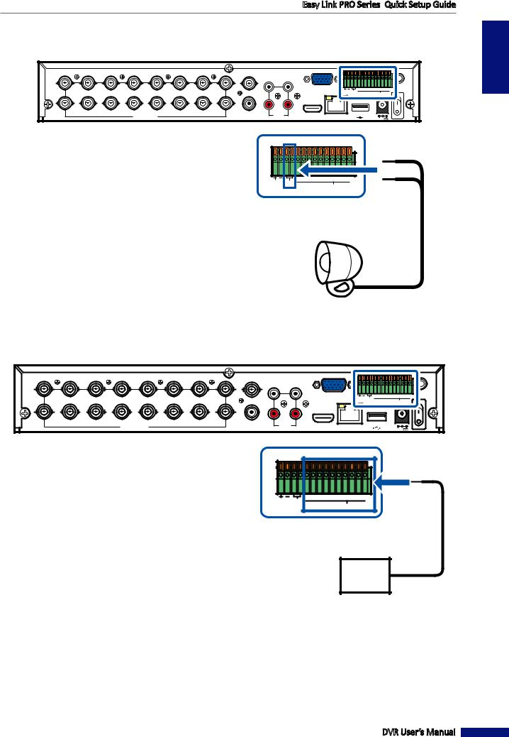
6. Connect the alarm device via Alarm and Sensor I/O block (optional).
NOTE: This feature is available only in 16-channel DVR.
|
|
|
|
|
|
|
VIDEO OUTPUT |
|
|
|
|
|
|
|
15 |
13 |
11 |
9 |
7 |
5 |
3 |
1 |
3 |
1 |
VGA |
|
|
|
IR-EXT |
RS-485 ALARM G |
1 |
2 |
3 4 G 5 6 7 8 |
|||||||||||
|
|
|
|
|
|
|
|
|
|
|
|
|
|
SENSOR |
16 |
14 |
12 |
10 |
8 |
6 |
4 |
2 |
4 |
2 |
|
|
|
|
|
|
|
|
|
|
|
|
||||||||
|
|
|
VIDEO INPUT |
|
|
|
AUDIO |
AUDIO |
|
HDMI |
LAN |
|
|
12V |
|
|
|
|
|
|
|
OUTPUT |
INPUT |
|
|
|
RS-485 ALARM |
G 1 2 3 4 G 5 6 7 8 |
|
SENSOR |
Alarm out
ENGLISH
Alarm device (output)
7. Connect sensors up to 8 channels (optional).
NOTE: This feature is available only in 16-channel DVR.
|
|
|
|
|
|
|
VIDEO OUTPUT |
|
|
|
|
|
15 |
13 |
11 |
9 |
7 |
5 |
3 |
1 |
3 |
1 |
VGA |
|
IR-EXT |
RS-485 ALARM |
G 1 2 3 4 G 5 6 7 8 |
|||||||||||
|
|
|
|
|
|
|
|
|
|
|
|
SENSOR |
16 |
14 |
12 |
10 |
8 |
6 |
4 |
2 |
4 |
2 |
|
|
|
|
|
|
|
|
||||||||
|
|
|
VIDEO INPUT |
|
|
|
AUDIO |
AUDIO |
|
HDMI |
LAN |
12V |
|
|
|
|
|
|
|
OUTPUT |
INPUT |
|
RS-485 ALARM
G 1 2 3 4 G 5 6 7 8
SENSOR
Sensor in
Sensor device (input)
DVR User’s Manual
17

ENGLISH
Easy Link PRO Series: Quick Setup Guide
Step 4: Power ON the DVR
Follow the instructions on the diagram, to power on the DVR.
NOTE: The 4-channel / 8-channel DVR do not have a classical power switch. The device starts up automatically after you apply the power via power adapter. As to 16-channel DVR, after you apply the power via power adapter, use the Power switch to turn on the DVR.
|
|
|
|
|
|
4-Channel DVR / 8-Channel DVR |
|
|
|
|
|
VIDEO |
|
|
|
|
|
|
|
OUTPUT |
|
|
CAUTION |
|
|
|
|
|
|
|
RISK OF ELECTRIC SHOCK |
|
|
|
|
|
|
|
DO NOT OPEN |
|
|
|
|
|
|
|
LAN |
7 |
5 |
3 |
1 |
1 |
|
|
|
|
|
|
|
|
|
|
|
8 |
6 |
4 |
2 |
2 AUDIO |
|
|
|
VIDEO |
|
VIDEO |
AUDIO |
HDMI |
VGA |
RS-485 12V |
|
INPUT |
|
INPUT |
OUTPUT |
INPUT |
|||
|
|
|
|
|
|
|
16-Channel DVR |
VIDEO OUTPUT
15 |
13 |
11 |
9 |
7 |
5 |
3 |
1 |
3 |
1 |
VGA |
RS-485 ALARM G 1 |
2 3 4 G 5 6 7 8 |
|
|
|
|
|
|
|
|
|
|
|
|
SENSOR |
16 |
14 |
12 |
10 |
8 |
6 |
4 |
2 |
4 |
2 |
|
|
|
|
|
|
|
|
||||||||
|
|
|
VIDEO INPUT |
|
|
|
AUDIO |
AUDIO |
|
HDMI |
LAN |
12V |
|
|
|
|
|
|
|
OUTPUT |
INPUT |
|
|||
B) Plug in the power |
|
|
|
|
|
|
|
|
|
C) Switch on the DVR. |
||
|
|
|
|
|
|
|
|
|
NOTE: This applies only |
|||
adapter to the power |
|
|
|
|
|
|
|
|
|
|||
|
|
|
|
|
|
|
|
|
to 16-channel DVR. |
|||
outlet. |
|
|
|
|
|
|
|
|
|
|
|
|
|
|
|
|
|
|
|
|
|
|
|
|
|
|
|
|
|
|
|
|
|
12V |
|
|
|
|
A) Connect the power adapter to the Power input on the rear of the DVR.
After the DVR is powered on, the Startup Wizard appears on your monitor/TV screen (please see the next step). If it is the first time you power ON the DVR, we recommend to go through the wizard and fill in the various setup options available.
NOTE: If you decide to skip the Startup Wizard, you can still access all the setup options later via the DVR’s OSD menu.
DVR User’s Manual
18
Easy Link PRO Series: Quick Setup Guide
Step 5: Go through the Items in Startup Wizard
For going through the items on Startup Wizard, the most convenient way is to use the supplied USB mouse. See the USB mouse operations in “Using the Supplied USB Mouse” on page 34.
The wizard includes setup screens which allow you to choose how you want the DVR to operate. All items on the wizard are also accessible via the DVR’s Main Menu (see “Main Menu” on page 53).
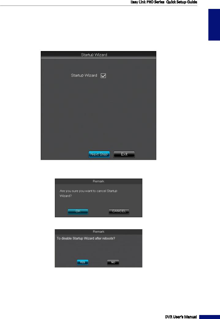
Startup Wizard
If you do not want to go through the Startup Wizard but access the Live Viewing screen immediately (step 6), you can click Exit. A confirmation message appears on the screen, click OK.
If you want to disable the Startup Wizard after reboot, click Yes.
NOTE: All the items on Startup Wizard can be accessed also through the DVR’s Main Menu.
Click Next Step to move to the next screen.
DVR User’s Manual
ENGLISH
19
Easy Link PRO Series: Quick Setup Guide
ENGLISH
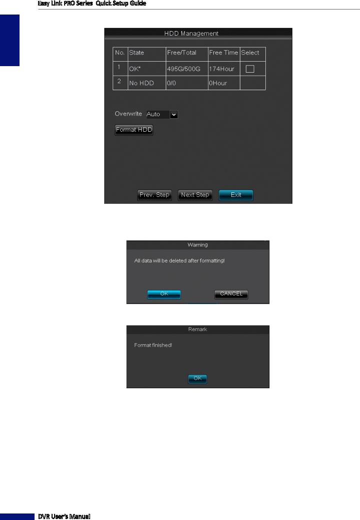
HDD Management
If you start up the DVR for the first time, you need to format the HDD. Only then the DVR can record the footages on it. To format the HDD, check the Select checkbox and click Format HDD. A warning message opens where you are asked to confirm your selection. Click OK.
Wait for the Format finished! notification message to appear on the screen. Click OK.
NOTE: Next time you startup the DVR, the recording from the cameras is performed automatically, or based on a defined schedule, and you do not need to reformat the HDD again, unless there is a problem with the hard disk.
Overwrite: Use this option to overwrite the old recordings on the HDD when the HDD is full. For example, if you choose the option 7 days then only the last 7 days recordings are kept on the HDD. To prevent overwriting any old recordings, select Disable.
Click Next Step to move to the next window.
DVR User’s Manual
20
Easy Link PRO Series: Quick Setup Guide
Record Schedule
ENGLISH
If you know the recording schedule in advance, you can define it in this step but you can do it also later via OSD menu. Please be noted that after you format the HDD, the default continuous recording from the connected cameras start automatically.
Channel: Select the channel where you want to apply the schedule.
Week: Select the day of the week where you want to apply the schedule. For example, after you define the schedule for Monday, you can use the Copy function to apply the same schedule for Tuesday ~ Friday.
Normal (N) Recording: When the time slot is marked green, it means the channel performs normal recording for that time slot. If you do not want to record all 24 hours in a specified day, click on the green slot to mark it No Record (gray slot).
Motion (M) Recording: When the time slot is marked yellow, it means the channel records only when a motion is detected during that time slot. We recommend to use this type of recording. The motion recording means that the recording is triggered only if a movement is detected.
Alarm Recording (for 16 channel only): When the time slot is marked red, the channel records only when the alarm is triggered during that time slot.
Click Next Step to move to the next screen.
DVR User’s Manual
21
ENGLISH
Easy Link PRO Series: Quick Setup Guide
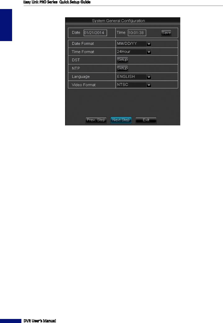
System General Configuration
It is very important that the time and date are set correctly. In case of a robbery, for example, the video footage can be used as an evidence in the court, and if the date and time do not match, the footage is not regarded as a legitimate evidence.
Date and Time: The current date and time are displayed on the screen. To change the date and/or time, you need to click on the corresponding field and do the modifications via the on-screen keyboard. After the changes are done, click the Save button.
Date Format: Choose how you would like the date to appear on the screen. We recommend to use the standard formats in your location.
Time Format: Choose how you would like the time to appear on the screen. The available options are 24-hour format or 12-hour format.
DST: Configure the Daylight Saving Time if it is applicable in your region. By default the DST is set Disable.
NTP: Skip the NTP (Network Time Protocol) for the time being because it requires an active Internet connection. By default, this item is enabled. It means that the time and date is updated automatically after the DVR is connected to the Internet. However, we suggest to set the date and time manually at this stage.
Language: Choose the preferred language you wish the menu items to appear on your DVR.
Video Format: Here you can choose the video format. The available options are NTSC and PAL. NTSC is used in Japan, Canada, US. PAL is used in Western Europe and Australia. If the DVR’s picture is flickering or has only black and white color, it may be that the video format is not correct.
Click Next Step to move to the next screen.
DVR User’s Manual
22
Easy Link PRO Series: Quick Setup Guide
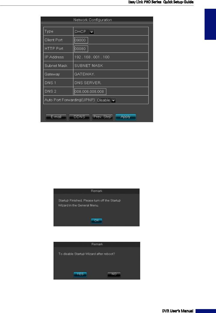
Network Configuration
ENGLISH
Network settings should be configured if you want to connect to the DVR remotely for live viewing or for example, if you want the DVR to synchronize the date and time automatically.
Type: Select the network type you are using. The most common types are DHCP or Static. Most probably your network type is DHCP, unless the network is manually addressed (usually called- Static).
NOTE: If your network type is Static, ask your ISP for assistance on determining the IP address, Subnet mask, Gateway, and DNS 1/2 server. If your network type is DHCP, your DVR will obtain the connection parameters, like IP address, Subnet Mask, Gateway and DNS 1/(2) automatically.
Client Port and HTTP Port: For time being, keep the default port values. Client and HTTP ports are important to configure before accessing the DVR remotely from a PC via HTTP Interface or smart phone/tablet.
For the first time startup, you do not need to configure Email or DDNS.
Click Apply. A notification message appears on the screen, click OK.
Another notification messages appears on the screen, asking your confirmation to disable Startup Wizard after reboot.
Click Yes.
The DVR will reboot.
DVR User’s Manual
23

ENGLISH
Easy Link PRO Series: Quick Setup Guide
Step 6: Make Sure the Camera(s) are Functioning
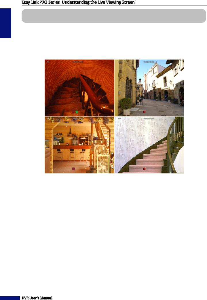
After you complete Step 5, you should be able to see the Live Viewing screen.
For more information, please see “Understanding the Live Viewing Screen” on page 26.
NOTE: The number of live views depend on your DVR type (4-channel, 8-channel, or 16-channel), and how many cameras you have connected to the DVR.
4-Channel DVR
DVR User’s Manual
24

Easy Link PRO Series: Quick Setup Guide
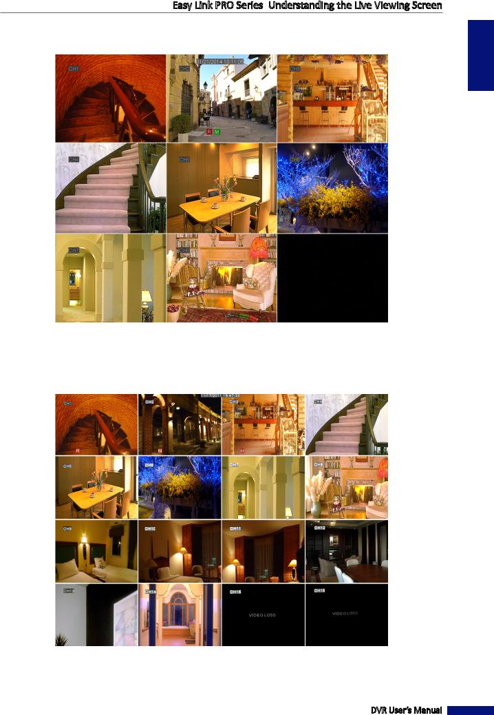
8-Channel DVR
ENGLISH
16-Channel DVR
DVR User’s Manual
25
ENGLISH
Easy Link PRO Series: Understanding the Live Viewing Screen
Understanding the Live Viewing Screen
First sceen you see after going through or skipping the Startup Wizard, is the Live Viewing screen. It is considered the main screen. On this screen you see the live views from all connected cameras.
• 4 Split Screen
Live Viewing Screen (4 Cameras Connected)
DVR User’s Manual
26
Easy Link PRO Series: Understanding the Live Viewing Screen
• 9 Split Screen
Live Viewing Screen (8 Cameras Connected)
• 16 Split Screen
Live Viewing Screen (14 Cameras Connected)
ENGLISH
DVR User’s Manual
27
ENGLISH
Easy Link PRO Series: Understanding the Live Viewing Screen
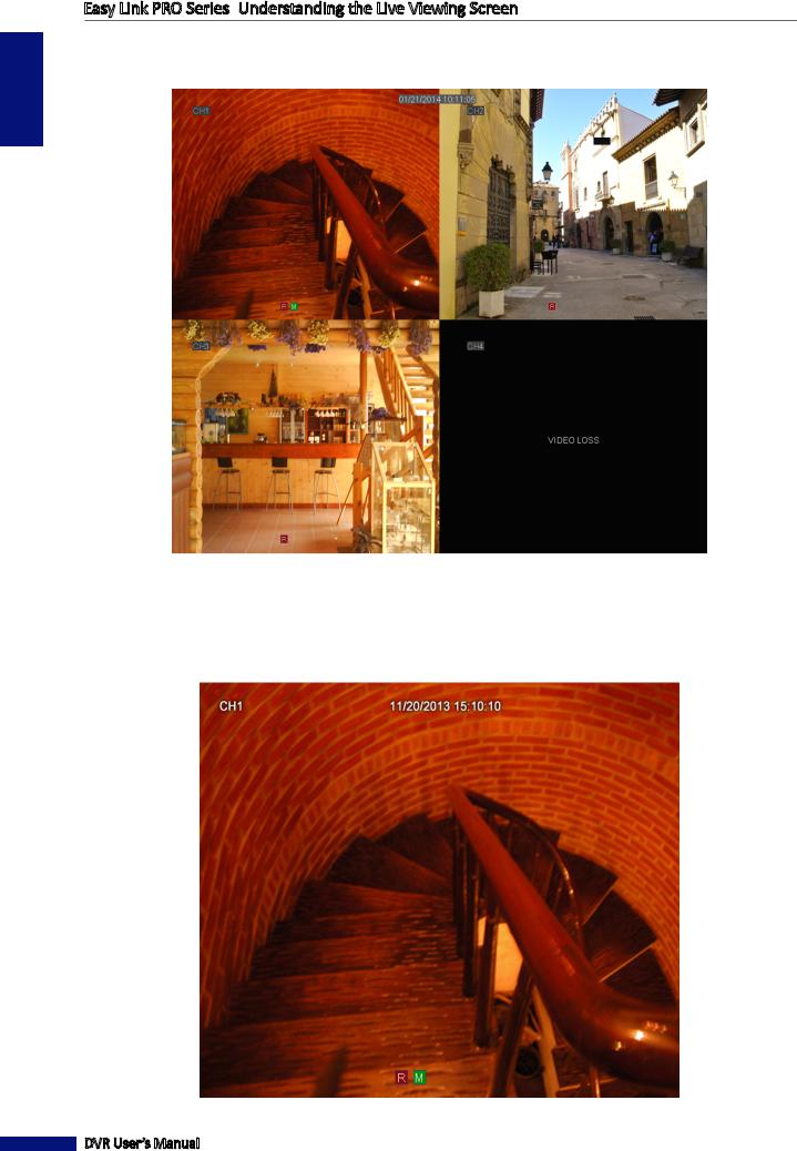
Those channels that do not have any cameras connected, are in the status “Video Loss”.
Live Viewing Screen (Video Loss)
• Full Screen Mode (one channel in full screen)
You need to double click on a channel live view, to see the channel in full screen. If you want to exit the full screen mode, double-click, again.
Live Viewing Screen (Full Screen Mode)
DVR User’s Manual
28

Easy Link PRO Series: Understanding the Live Viewing Screen
The Live Viewing Screen Icons
On a Live Viewing Screen, you can see the channel name, current date and the recording indicator. These indicators inform you if the video recording is in process, is the motion detected, has the (internal) HDD failed, or is there a connection to the camera.
Channel name |
Current date & time |
Recording indicator
The meaning of the indicators is as follows:
Icon Description
MIf you see this icon on a live view, it means a motion has been detected on that channel. By default motion detection is activated for all cameras. If you want to modify this setting, see “Alarm: Motion” on page 76.
If you see this icon on a live view, it means the DVR cannot detect a HDD or the HDD is not formatted.
HPlease make sure you have installed a HDD into the DVR, see
“Step 2: Install the Hard Disk Drive (HDD)” on page 8 or see “Device: HDD” on page 78.
R |
M |
If you see this icon on a live view, it means the video recording is in progress. By default the video |
/recording is enabled for all channels. if you want to change this option, you can disable the recording of a channel, see “Record: REC Para” on page 59.
•R: Indicates normal recording.
•M: Indicates motion/alarm triggered recording.
VIDEO LOSS Camera is not connected to the DVR.
DVR User’s Manual
ENGLISH
29
ENGLISH
Easy Link PRO Series: Understanding the Live Viewing Screen
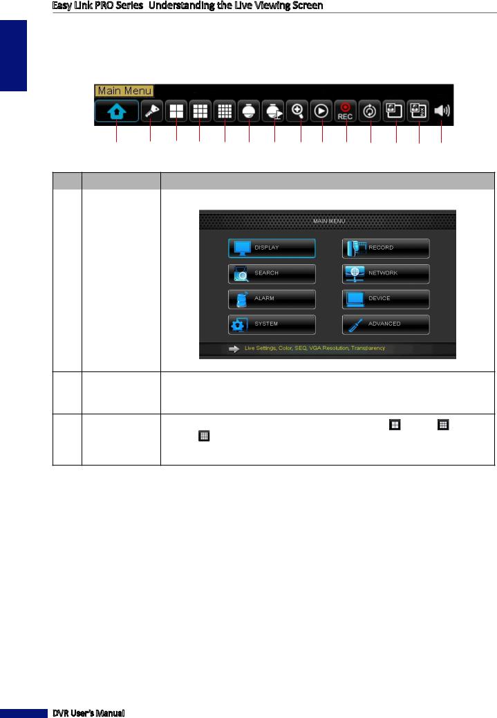
Pop-Up Menu on Live Viewing Screen
Via Pop-up menu you can access the Main Menu, for making modifications to the DVR’s configuration and other common features. To bring up the Pop-up Menu, click on the right mouse button on Live Viewing screen or press the MENU button on the remote control.
1 2 3 4 5 6 7 8 9 10 11 12 13 14
No. |
Button |
Description |
|
|
|
|
Main Menu |
This is the Main Menu where you can configure all the settings of the DVR. |
1
Lock |
Lock access to enter the OSD menu. You need to type the user name and password |
2before entering the OSD menu.
NOTE: The default user name and password are “admin” and “123456“.
|
Screen View |
Depending on your DVR’s model, switch to a 4-split display ( ), 9-split ( ), or |
3,4,5 |
(4-split / 9-split / |
16-split ( ) display. For example, you may want to use this function, after viewing |
16-split) |
channels in a full screen mode or in a sequence, and wish to switch back to a 4-split, |
|
|
|
9-split, or 16-split display. |
DVR User’s Manual
30
Loading...