

Page 1
User Manual
Page 2

User Manual
CONTENTS
Safety Instructions……………………………..……………………………………….…………….1
Chapter 1. DVR Features ………………….………………………………………………………2
Chapter 2. Layout
…………………….……………………………………………….……………..3
2.1. Front Panel …………………………….……………………………………….………………3
2.1.1. 4-CH Front Panel………………..………………………………………………..…….3
2.1.2. 8-CH Front Panel ………………..………………………………………… ………….4
2.2. Rear Panel ………………………………..………………………………………..…………..5
2.3. Remote Control……………………………...…………………………………….…………6
Chapter 3. DVR Installation……………………………………………………………………….7
3.1. Hard Drive Installation ……………………………………………………………………7
3.2. Camera and Monitor Connection …………………………………………………………8
3.3. Power Supply connection…………….……………………………………………………8
Chapter 4. DVR Boot Up
……………………..……………………………………………….……9
4.1. System Initialization …………………..………………………………………………….9
4.2. Main Interface………………………..…………………………………………….……9
Chapter 5. DVR Menu …………………………………………………………………….………10
5.1. Main Menu Preview …………………………………………………………………….……10
5.2. Main Menu ……………………………………...………………………………….…………11
5.2.1. Camera Setup…………………………………………………………………….……11
5.2.1.1. Color Setup …………………………………………………………………….11
5.2.1.2. Privacy Zone Setup
…………………..…………………………………………12
5.2.1.3. Autoseq Setup
………………………………………………………………….12
5.2.2. Record Setup ………………………………………………………………….………13
5.2.2.1. Record Mode ……………………….………………………………………….13
5.2.2.2. Record Schedule Setup
……………….…………………………………………13
5.2.2.3. Manual Recording
…………………...…………………………………………14
5.2.3. Recording Search & Playback ………………………..………………………………14
5.2.3.1. Search …………………………………………………………………….…14
5.2.3.2. Playback Interface
………………………………..……………………………15
5.2.3.3. Video Backup
……………………………………………..……………………15
5.2.4 Device Management …………………………………………….…………………….16
5.2.4.1. HDD Management………………………………………………………………16
5.2.4.1.1. HDD Format
…………………………………………………………………17
5.2.4.2. Alarm Setup
……………………………………………...…………………….17
5.2.4.2.1. Email Alarm Notification
………………………………...……………………18
5.2.4.3. Motion Detection Setup
…………………………………………………………19
5.2.4.4. PTZ Setup
……………………………………………….…………….………19
Page 3

User Manual
5.2.4.5. PTZ Control …………………………………………………...……………….19
5.2.5. System Setup ……………………………………………………………………….…20
5.2.5.1. Time Setup ………………………………………………………………….…20
5.2.5.2. Password
……………………………………………………...…………….…21
5.2.5.2.1. Menu Lock
…………………………………………………..……………… 21
5.2.5.3. Video Setup
……………………………………………………………….… 22
5.2.5.4. Language
…………………………………………………...……………….…22
5.2.5.5. Info
………………………………………………………...……………….…22
5.2.5.6. System Maintenance
……………………………………………………………22
5.2.6. Network Setup…………………………………………………….……………….… 23
5.2.6.1. Intranet/LAN Access Setup………………………………...…………………… 23
5.2.6.2. Internet Access Setup
…………………………………...………………………24
5.2.6.3. Ports
………………………………………………….…………………….…25
Chapter 6. Network Access …………………………………………………………………….…26
6.1 IE & Netviewer Access ………………………………………………………………….….…26
6.1.1. IE Setup…………………………………………………………………………….… 26
6.1.2. Connect to DVR………………………………………………………………...….… 27
6.1.2.1. IE Plug-in & Netviewer Interface…………………………………………..…… 27
6.1.3 Control Network Access …………………………………………………….………28
6.1.3.1 Live …………………………………………………………………...…….…28
6.1.3.2. Setup
……………………………………………………………………….…28
6.1.3.3. Replay
………………………………………………………………….… …..28
6.1.3.4. Convert 264 file to AVI file
……………………………………………………28
6.1.3.5. Remote Backup
…………………………………………………………… …..29
6.1.3.6. PTZ Control
……………………………………………………………………29
6.1.3.7. Logout
………………………………………………………………………...29
6.1.3.8. Playback Local File with Netviewer
…………………………………………… 30
6.2 Mobile Phones Access …………………………………………………..………………….…31
6.2.1 Mobile Setup…………………………………………………………………………...31
6.2.1.1. Install & Operate Mobile Client in Windows® Mobile Phones…………………… 31
6.2.1.2. Install & Operate Mobile Client in Symbian® Phones
……………..………………33
6.2.1.3. Install & Operate Mobile Client in iPhone
®
……………………….……………… 35
Chapter 7. Specifications……………………...………………..………………………………… 40
Chapter 8. System connection Configuration………………..……………………………… 42
Chapter 9.Appendix………………………………………………………………………………...44
9.1. Operation Function Table……….…………………………………………………………...44
9.2. Recording Alarm Setting……….……………………………………………………………45
9.3. Troubleshooting………………...…………………………………………………………...45
9.4. Email server check list (The below info only o for your ref)...…………………………….46
9.5. Usage Maintenance……………...…………………………………………………………..46
Page 4

1
Safety Instructions
1. Use proper power source.
Do not use this product with a power source that applies more than specified voltage (100-240V AC).
2. Never insert anything metallic into the DVR case.
Putting something into the DVR case can be a source of dangerous electric shock.
3. Do not operate in wet & dusty area or use near water.
Avoid places like a damp basement or dusty hallway.
4. Do not expose this product to rain or use near water.
If this product accidentally gets wet, unplug it and contact an authorized dealer immediately.
5. Keep product surfaces clean and dry.
To clean the outside case of the DVR, use a cloth lightly dampened with water (no solvents).
6. Do not attempt to remove the top cover.
If there are any unusual sounds or smells coming from the DVR, unplug it immediately and contact an
authorized dealer or service center.
7. Do not attempt to remove the top cover.
Warning: You may be subjected to severe electrical shock if you remove the cover of the DVR.
8. Handle DVR box carefully.
If you accidentally drop your DVR on any hard surface, it may cause a malfunction. If the DVR doesn’t work
properly due to physical damage, contact an authorized dealer for repair or exchange.
9. Use standard lithium cell battery. (NOTE: Manufacturer has preinstalled battery.)
The standard lithium cell 3v battery located on the mother board should be replaced if the time clock does not
hold its time after the power is turned off. Warning: unplug the DVR before replacing battery or you may be
subjected to severe electrical shock. Properly dispose of old batteries.
10. Make sure there is good air circulation around the unit.
This DVR system uses a hard drive for video storage, which generates heat during operation. Do not block air
holes (bottom, upper, sides and back) of the DVR that cool down the system while running. Install or place this
product in an area where there is good air circulation.
Page 5

2
Chapter 1. DVR Features
Real time monitoring Supports real time surveillance via Monitor
Save Recordings DVR saves real-time recording image to HDD
Backup Recordings Supports DVR backup via USB flash drive and hard drive.
Playback Recordings Supports DVR single CH and multiple CH playback of recorded files
Network operation Supports remote surveillance by multiple users simultaneously
Alarm Setting Supports HDD & video input alarm management
Mouse Operation Supports Mouse operation for faster menu navigation.
PTZ Control Supports PTZ camera operations through RS-485.
Other Features:
H.264 real-time high compression and supports dual stream network transmission
Graphics & Windows OSD interface
ADPCM audio compression
Supports pentaplex operation: live view, record, playback, backup and network transmission
Supports backup & upgrade with USB flash disk
Supports DDNS
Supports audio transmission via network
Selectable packing time for recorded files
Supports editing camera title
Supports adjusting image color
Event camera pop-up function
Supports remote view with mobile phones based on Symbian S60 3
rd/5th
edition, Windows Mobile, iPhone &
Blackberry
Supports VGA output (max. resolution: 1920 x 1200)
Alarm modes: video loss, HDD full, HDD loss ,Motion detection,
Email alert function
With free-drag digital zoom function for live viewing
Multiple languages OSD
Supports auto maintenance
Page 6
3
Chapter 2. Layoutt
2.1. Front Panel
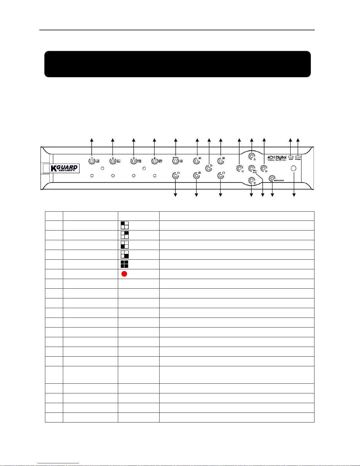
2.1.1. 4-CH Front Panel
Item Key/Indicator Marks Functions
1 CH1
Select Channel 1 to be full screen displayed
2 CH2
Select Channel 2 to be full screen displayed
3 CH3
Select Channel 3 to be full screen displayed
4 CH4
Select Channel 4 to be full screen displayed
5
QUAD
Select quad display
6 REC
Start manual recording
7 REW
Move leftward / Rewind
8 PAUSE
Pause / play frame by frame
9 PLAY
Enter into playback mode / Play button
10 FWD
Move rightward / Play forward
11 STOP
Stop Playback / stop manual recording
12 LEFT
Enter into main menu or exit menu
13 UP
Move Up
14 DOWN
Move Down
15 RIGHT
Move rightward / Play forward
16 SEL/PTZ SEL/PTZ
Enter system pop-up (short cut) menu bar/ edit button / enter
PTZ mode
17 MENU/ESC MENU/ESC
Enter/exit system menu
18 HDD indicator HDD
Continuous flicker indicates HDD is being accessed
19 Power indicator PWR
Green light indicates power supply status
20 IR Receiver
To receive signal from remote controller
1 2 3 4 5 7 9 10 12 13 18 1915
6
8 11 14 16 17 20
Page 7
4
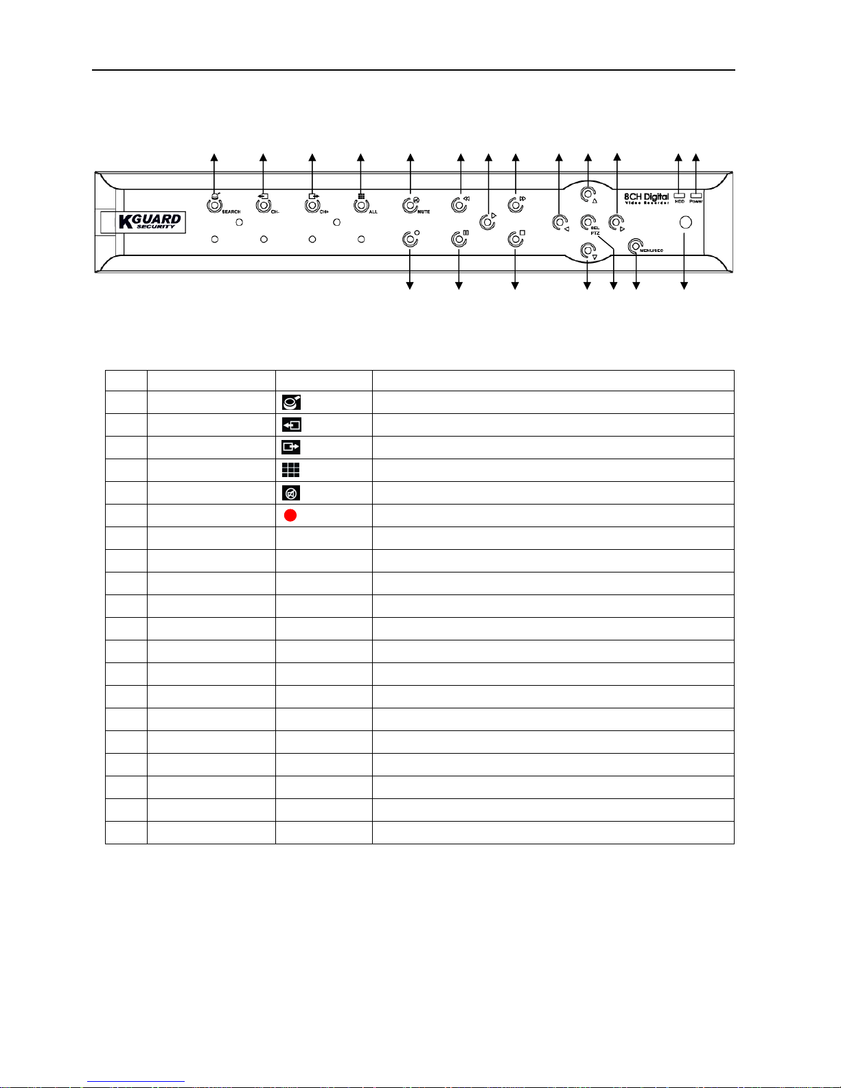
2.1.2. 8-CH Front Panel
Item Key/Indicator Marks Functions
1 SEARCH
Enter system pop-up (short cut) menu bar
2 CH-
Switch to previous channel
3 CH+
Switch to next channel
4 ALL CH
Switch to 4/8 pictures display
5
MUTE
Audio mute key
6 REC
Start manual recording
7 REW
Move leftward / Rewind
8 PAUSE
Pause / play frame by frame
9 PLAY
Enter into playback mode / Play button
10 FWD
Move rightward / Play forward
11 STOP
Stop Playback / stop manual recording
12 LEFT
Move leftward / Rewind
13 UP
Enter into main menu or exit menu
14 Down
Move Up
15 RIGHT
Move rightward / Play forward
16 SEL/PTZ SEL/PTZ
Enter system pop-up menu bar / edit button / enter PTZ mode
17 MENU/ESC MENU/ESC
Enter/exit system menu
18 HDD indicator HDD
Continuous flicker indicates HDD is being accessed
19 Power indicator PWR
Green light indicates power supply status
20 IR Receiver
To receive signal from remote controller
1 2 3 4 5 7 9 10 12 13 18 1915
6
8 11 14 16 17 20
Page 8
5
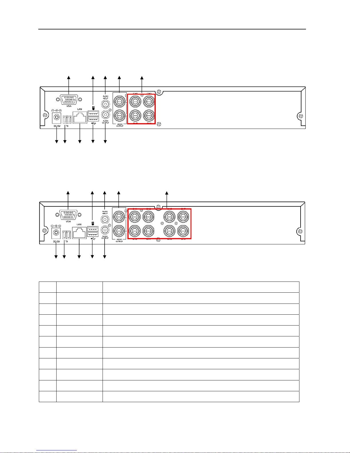
2.2. Rear Panel
4-CH Rear Panel
8-CH Rear Panel
Item Physical port Connection method
1 Video input Connect CH1-4/9 (BNC interface)
2 Video output Connect monitor output (BNC interface)
3 Audio input Connect 1 audio signal input (RCA interface)
4 Audio output Connect 1 audio signal output (RCA interface)
5 USB Port Connect USB mouse
6 USB Port Connect USB device (USB CD/DVD-RW, USB thumb disk, USB hard disk)
7 Ethernet: Port Connect intranet, internet (RJ45 interface)
8 VGA Port Connect to VGA monitor
9 RS-485 RS485 interface
10 Power Port Connect power supply - DC12V,3A
8 5 3 2 1
4 6 7 9 10
8 5 3 2 1
4 6 7 9 10
Page 9
6
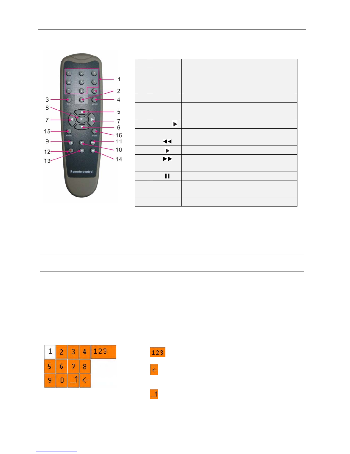
2.3. Remote Control
Mouse Operation
You can use a mouse instead of front panel keys or remote control to navigate the operation of your DVR
Left button of Mouse In OSD menu, click left button to select & edit
In live display mode, clicking right key will display pop-up menu bar
Right button of Mouse
In Main menu or sub menu mode, clicking right key will exit current menu.
Double-click Left button
of Mouse
double-click the live image of any channel for full screen display; by
double-clicking again, the display will return to display all cameras
Sliding Mouse On motion mode, sliding mouse will select motion area; On [Color Setup] menu
mode, sliding mouse will adjust color control bar and volume control bar.
Using the Virtual Keyboard – Mouse Only
When using the mouse, you can input certain values using the onscreen virtual keyboard.
You will need to use the Virtual Keyboard when entering your User ID and Password.
To use the Virtual Keyboard:
1 1-8
Channel Select 1-8 ; Numeric key
2
9、0
Numeric Key
3 ALL
Display all Channel
4 Menu
Enter/Exit Main Menu
5 ▲
Up Key
6
▼ Down Key
7
◄ /
Left / Right Key
8 SEL
Select Key/ Edit Key
9
Rewind key
10
Play Key, Enter to recording search menu
11
Forward Key
12
●
Manual Recording
13
Pause / Frame Play
14
■
Stop manual recording; Stop Playback
15 Audio
Undefined
16 Mute
Undefined
1. Click on an option or field, such as the User ID and Password fields.
2. Click 0~9 to enter the desired digit.
3. Click
to switch between numerals, upper and lowercase letters,
and other characters (only for certain options)
4. Click
to Backspace/Delete.
NOTE: The buttons will turn from orange to white when you select
the button with the mouse cursor.
5. Click
to enter/confirm and close the Virtual Keyboard.
Page 10
7
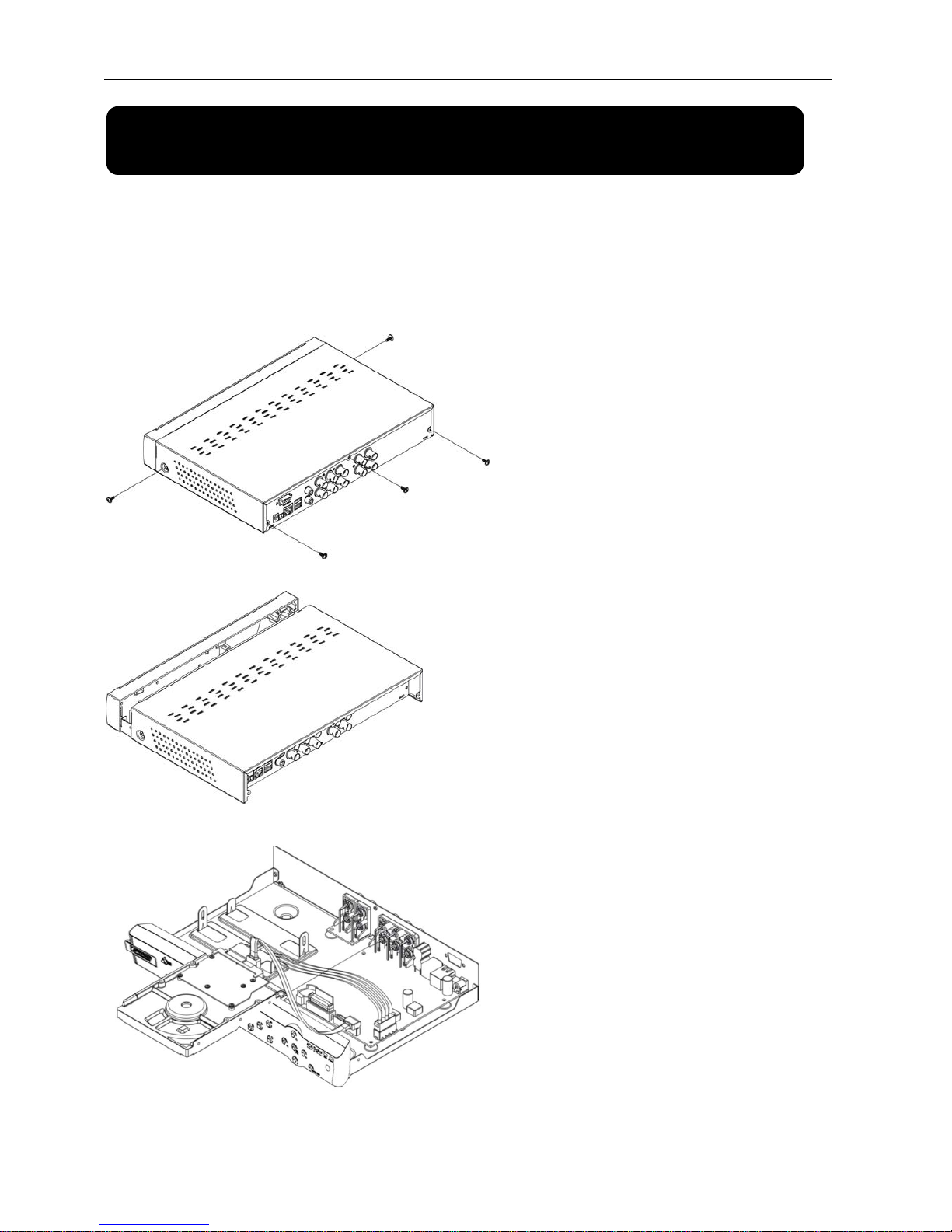
Chapter 3. DVR Installation
3.1. Hard Drive Installation
Caution: Please do NOT install or uninstall hard drive while DVR is running!
1. Loosen the screws in the left and right sides.
2. Remove the cover
3. Connect data cord and power cable.
Page 11
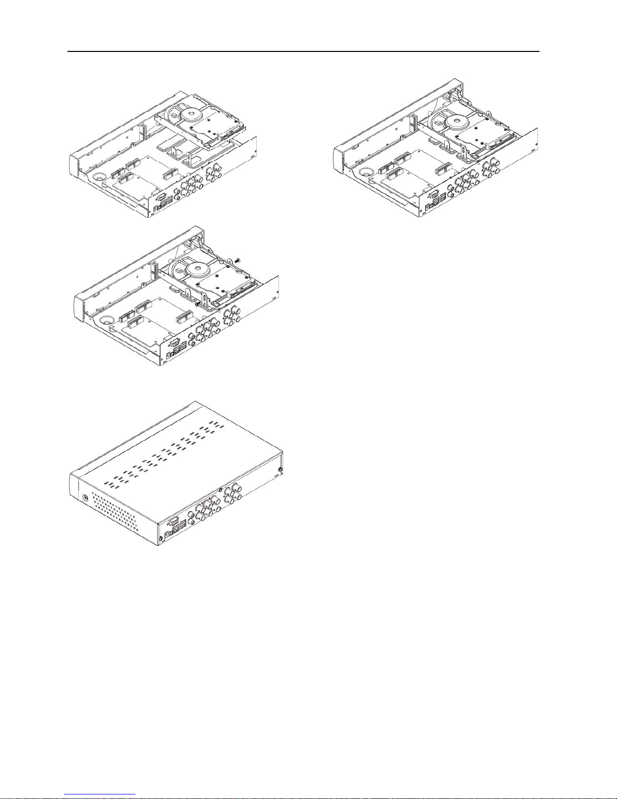
8
4. Install HDD on the bracket, fixed with screws firmly.
5. Check if the connectors are properly connected and there is no problem with wiring and close up
cover, and fix it with screws.
3.2. Camera and Monitor Connection
Connect camera cable to video input port of DVR, and from video output of DVR to Monitor via BNC
connector or VGA port (refer to system figuration on Chapter 9.6).
If the camera is a PTZ speed dome, you could connect RS485 A & B to the corresponding port on
DVR respectively (refer to system figuration on Chapter 9.6).
3.3. Power Supply connection
Please only use the power adapter supplied with the DVR.
Page 12
9
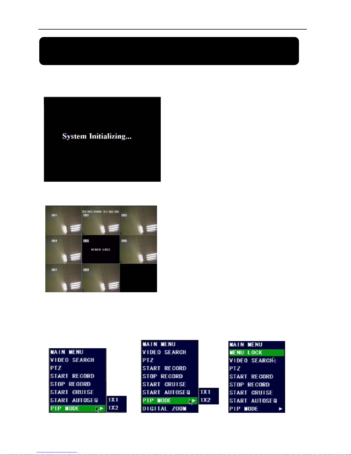
4.1. System Initialization
4.2. Main Interface
After initialization, the system will display main
interface. When there are video inputs, live images
from the cameras will be displayed on screen. You can
use mouse to double-click the live image of any
channel for full screen display; by double-clicking
again, the display will return to display all cameras.
On the main interface, you will be able to see current
system date & time, channel title, recording status.
When there is no HDD installed in the DVR, or the
HDD is in abnormal working condition, system will
display “H” on screen.
Press SEL button on the front panel or click the right button of mouse, you will be able to see the
pop-up menu bar. It’s a short cut for your quick jump to menus in common use. Detailed method to
operate the pop-up menu bar will be introduced in relative chapter.
After connecting the power adapter the system
will boot-up and start initializing.
Chapter 4. DVR Boot Up
Page 13

10
5.1. Main Menu Preview
Search
Camera
Record
System
Devices
Network
Main Menu
Search
Playback
File List
HDD Management
Alarm Setting
PTZ Setting
Mobile Phone Setup
Motion
Color setup
User Password
System Information
Language Selection
System Maintenance
Video Setting
Time Setting
Autoseq Setup
Camera Title
Privacy Setup
Record Quality
Record Solution (4CH)
Audio Record
Record Mode
Record File Size
DDNS Setup
Record Schedule
Area Setup
E-mail Setup
Backup
VGA Solution
TV System
Firmware Upgrade
Chapter 5. DVR Menu
Page 14
11
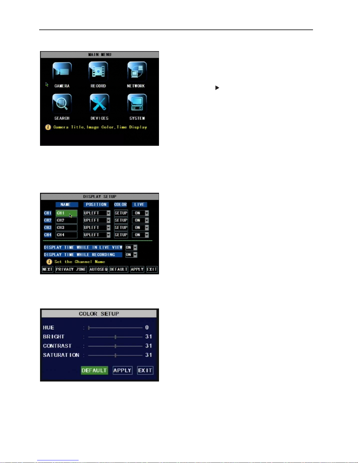
5.2. Main Menu
5.2.1. Camera Setup
Name: You are able to edit the title of the camera with letter and number. Max. 8 characters.
Position: Edit the position to display the camera title on screen.
5.2.1.1. Color Setup
Press SEL button on the front panel or click the right
button of mouse to display pop-up menu.
Select MAIN MENU to enter main OSD menu.
Press ▲, ▼, ◄, keys on front panel to move the
cursor, then press SEL key to enter selected item.
Or use you mouse to select and enter menu.
Press ESC key or click right button of mouse to
return to previous window
Live: Select to display live image or not. If you
select OFF, the image is still recorded and you can
see it in playback mode.
DISPLAY TIME WHILE IN LIVE VIEW: If you
select OFF, you will not be able to see the system
time display in live picture.
DISPLAY TIME WHILE RECORDING: If you
select OFF, you will not be able to see the system
time display in recorded picture while playing back.
Picture 5-2
You can adjust image brightness, saturation,
contrast and hue settings for each channel.
Press ▲ & ▼ key on front panel to adjust the
value, or drag the bar to adjust with you mouse.
Press APPLY button to save your settings.
Page 15
12
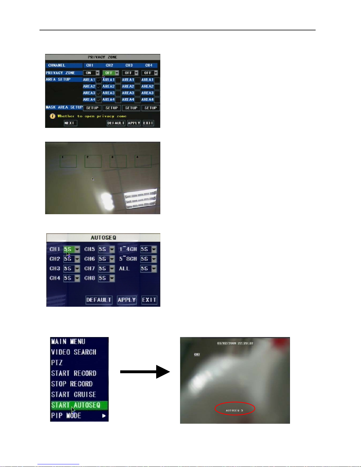
5.2.1.2. Privacy Zone Setup
5.2.1.3. Autoseq Setup
Go to main interface and trigger the pop-up menu bar, you will find the START AUTOSRQ menu.
Click it and the DVR will enter auto sequence display mode. Press any key will exit autoseq mode.
AUTOSEQ allows system to display every
selected channel in full screen by certain dwell
time, and auto-switch in sequence.
Default dwell time: 5 second
Selectable time range: 0~10 seconds
2. Press SETUP button to adjust the position of the
privacy zones
3. After finishing the position adjustment, press ESC
key on front panel or click right button of mouse to
exit and return to PRIVACY ZONE page.
4. Press APPLY to save you settings.
Privacy zone function allows you to cover the
private area, such as password input area on ATM
machines. The covered areas will not be able to see
in live view mode or in playback mode.
You can select max. 4 privacy zones for each
channel.
1. Select the No. of area (AREA1 – AREA4) you
want to set
Page 16

13
5.2.2. Record Setup
5.2.2.1. Record Mode
5.2.2.2. Record Schedule Setup
Functions:
CHANNEL: ON/OFF option decides to record or
not.
RESOLUTION: (4-CH only) decides the recording
video resolution. About the definition of resolution,
please refer to the specification chapter.
QUALITY: select recording video quality, higher
quality will need more HDD space to save the video
AUDIO REC.: DVR supports to record 1 channel
audio signal. Here you can bind the audio channel to
an appointed video channel for together recording.
FILE SIZE: System record and save the videos to
HDD by separate files. It indicates the maximum
recoding length for every single continuous
recording file (15, 30, 45, 60 minutes).
There are 2 record modes: ALWAYS & TIME
SCHEDULE RECORD.
When you select ALWAYS record mode, DVR will
execute continuous recording without stop.
When you select TIME SCHEDULE RECORD
mode, DVR will execute recording according to your
schedule.
4-CH
8-CH
Select TIME SCHEDULE RECORD, a SCHEDULE
button will display. Click it and enter schedule setup
interface.
There are 3 recording status options:
ALARM [RED]: Motion detection mode
GENERAL [GREEN]: Continuous record mode
NO RECORD [Transparent]: Do not record
Page 17

14
You are able to config 24 hours recording schedule for every channel or all channel from Sunday to
Saturday.
Steps:
1. Select Channel
2. Select a recording status among ALARM, GENERAL and NO RECORD
3. Move the cursor to the time point you want to set, click on the box in the schedule time line that
you want to apply the selected record type to.
4. If you want to change another recording status, repeat step 2 & step 3.
5. You can use copy function to fast complete your settings.
6. Press APPLY button to save your settings.
On the main interface, you will be able to check the recording status:
R: normal recording
M: motion detection recording
5.2.2.3. Manual Recording
5.2.3. Recording Search & Playback
You can enter search & playback interface by pop-up menu bar or main menu.
5.2.3.1. Search
There are 2 short cut menus listed in the Pop-up menu: START
RECORD and STOP RECORD. They are Manual record &
manual stop record buttons and the START RECORD function
only work when current recording mode is as following
recording status:
1. NO RECORD
2. ALARM, but the motion is no happening now.
The STOP RECORD function can only stop manual recording.
Play back by exact date & time:
Modify the date & time, press PLAYBACK button to
play back video which is started from your appointed
date & time.
Page 18

15
Search All Recorded File:
Press SEARCH button, system will search and show you
the recorded status. RED color indicates ALARM
recoding, GREEN color indicates continuous recording.
You can click the time point to play back.
For 4-CH DVR, system will play back all 4 channels at
the same time.
For 8-CH DVR, system can play back 1 channel only at
the same time.
File list
To check recoding event list, you can sort the files by Channel / Record Type (Normal Record / Alarm
Record)
5.2.3.2. Playback Interface
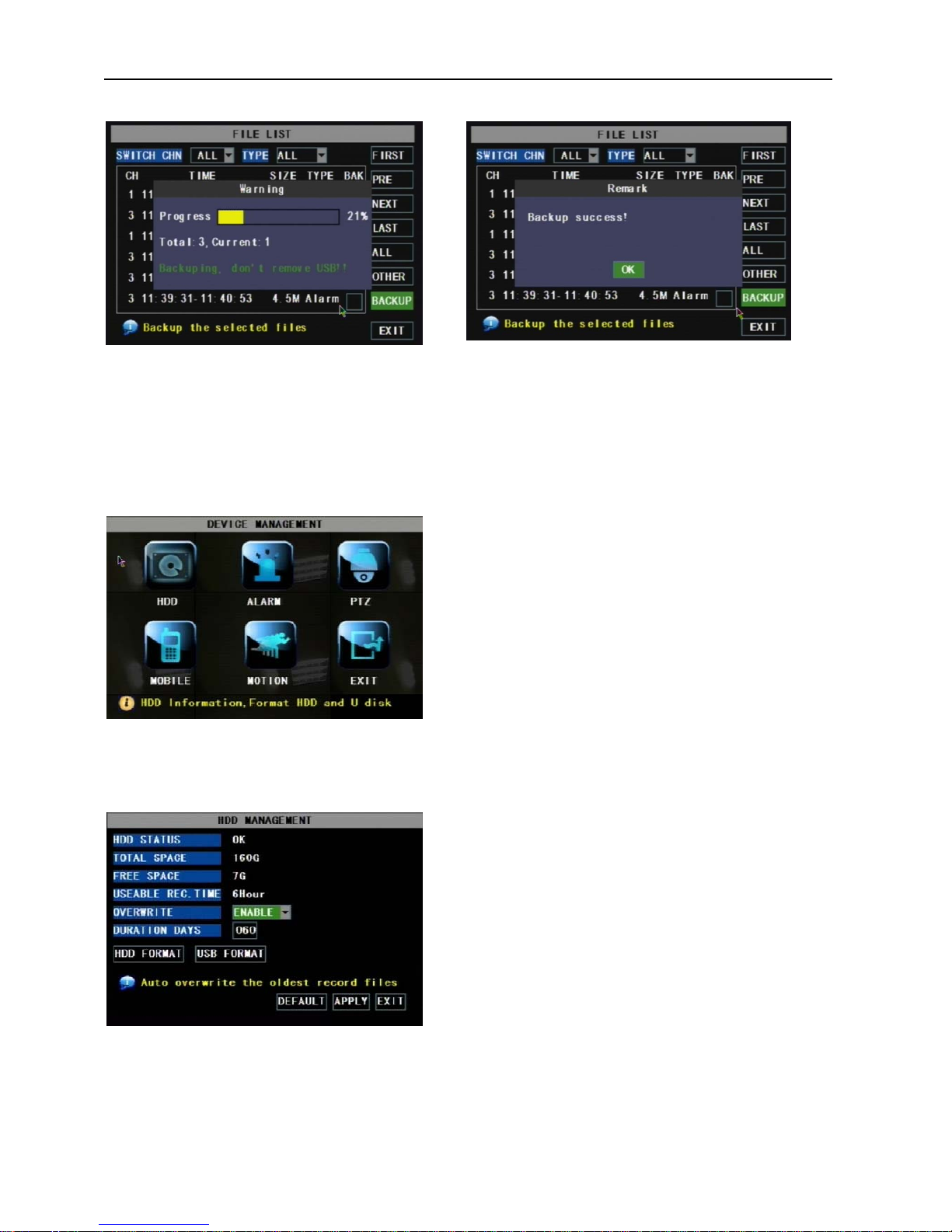
5.2.3.3. Video Backup
1. Insert your USB device (USB hard disk, USB thumb drive) into the bottom USB port on the rear
panel.
2. Select one or more files
3. Press BACKUP button on the menu.
FIRST: Turn to the first page
PREV: Turn to previous page
NEXT: Turn to next page
LAST: Turn to the last page
ALL: Select all files in current page
REVERSE: Allows you to revert the selected and
unselected events on the current page except those
you have currently selected.
You can play video Forward at 2x, 4x, and 8x
speeds, Slow play at 1/2x, 1/4x, 1/8x, or normal
play, pause and play frame by frame using the
playback control bar, and adjust volume by clicking
or sliding tune control bar. When playback is
finished, system will return to previous menu.
Page 19
16
NOTE: Do not remove your USB device during making backup.
Note: Backup files will be in H.264 format, you can play them with Netviewer program, or convert
them to AVI format using the Netviewer program that comes with the DVR, so you can use any player
that supports AVI format. (Introduced on Chapter 6)
5.2.4 Device Management
5.2.4.1. HDD Management
You will see the HDD information here.
HDD STATUS: HDD working status
TOTAL SPACE: HDD capacity
FREE SPACE: HDD free space
USABLE REC. TIME: estimated recording length of
the HDD free space
OVERWRITE: If you select DISABLE, DVR will
stop recoding when HDD is full; if you select ENABLE,
DVR will continuous record and cover the oldest data
when HDD is full.
DURATION DAYS: option for you to set that how
many days the video will be saved in the HDD. For example, if you set as 10, DVR will automatically
delete the data which was saved 10 days ago, that means you can only search & play back the data
which was saved in the past 10 days. The maximum value is 60 days.
Options in device management include
Hard drive, Alarm, PTZ control, Mobile
Phone Monitoring, and Motion Detection.
Page 20

17
5.2.4.1.1. HDD Format
When a new HDD is installed into the DVR, the HDD
status will show “NOT FORMATED”. You need to
format the HDD otherwise the system cannot record.
Warning: If you format a HDD which is being
currently used, all data saved in the HDD will be lost!
System will restart automatically after formatting the
HDD.
USB FORMAT: to format USB devices.
5.2.4.2. Alarm Setup
BUZZER:
Option to turn OFF the built-in buzzer alarm, or set the
buzzer alarm time.
MD ALARM: Option for buzzer to alarm or not when
the motion detection happens
HDD LOSS: Option for buzzer to alarm or not when
there is no HDD installed in the DVR, or the HDD is in
abnormal working condition.
HDD SPACE: Option for buzzer to alarm or not when
HDD space is full (if you have turned off the HDD overwrite function).
VIDEO LOSS: Option for buzzer to alarm or not when video signal loss.
FULL SCREEN: Option to pop up the channels to full screen display or not when motion detection
happens.
ALARM TIME:It determines the motion detection recording length, which means how long the
motion detection recording will still record after motion stops.
EMAIL: Option to send live images by email when motion detection happens.
5.2.4.2.1. Email Alarm Notification
Warning: We don’t promise every email server is compatible with the DVR alarm
notification function. Please make sure your DVR is well connected to Internet if you want to
realize Email alarm function,
SSL is a security link transport protocol. You can encrypt your communication info (including
your email) using SSL to prevent hackers from monitoring your email or communication info and
even your password. Please confirm with your email service provider if your email server support SSL
or not.
Page 21

18
Take GMAIL for example to demonstrate the email setting:
1. Set SSL to “On” via Gmail.com server, and set to “Off” via other mail server.
2. SMTP Port: indicates sender port of SMTP server. Generally the SMTP port value is 25, SMTP
port of G-mail server is 465.
3. SMTP: smtp.gmail.com
4. SEND EMAIL: dvrtest@gmail.com
5. SEND PW: enter the login password of send email
6. RECV EMAIL: The email address is used to receive image transmitted from motion detection
alarm of DVR.
7. Login your Gmail ID and turn to Settings page. Find out Forwarding and POP/IMAP option,
then enable IMAP function.
Page 22

19
5.2.4.3. Motion Detection Setup
5.2.4.4. PTZ Setup
5.2.4.5. PTZ Control
STATUS: This option allows you enable motion
detection on the channels.
SENSITIVITY: This option allows you to set
sensitivity level of motion detection from 1 to 4
with 4 being the most sensitive.
MD AREA (motion detection area): Click this
button of the corresponding channel to select the
area you want to have motion detection. The
channel is separated into a 13*10 area. When any
movements in the selected area are detected,
recording or alarm will be triggered.
Red area: motion detection enabled
Transparent area: motion detection disabled
Select the channel you want to control and
set PTZ (Pan Tilt Zoom) protocol (Pelco-D
or Pelco-P), Baud Rate (1200, 2400, 4800,
9600), Stop bit (1, 2), Parity Check (None,
Odd, Even Mark Space), Address Code and
Cruise status respectively. Please note the
above mentioned channel settings must
match the settings of the PTZ camera.
You can find the PTZ control menu on the pop-up menu bar
and open the PTZ control interface. You can click Z+ & Zkeys to zoom In or out, click F+ & F- keys to control camera
focus and click I+ & I- to adjust the focus point.
Page 23

20
Open auto cruise function on PTZ setting menu if you want to setup cruise function, and set up cruise
channel, cruise point, total quantity and stop time (by second) etc.
Channel: select the channel with the PTZ camera
TOTAL: set up presetting bit (angle) quantity. Please refer
to your camera’s manual for detail
CUR POINT: System has default starting (current) cruise
point as 01. You can use this option to set additional cruise
points
STOP TIME: sets the dwell time at each cruise point
GOTO: Select this option to go to specific preset points
5.2.5. System Setup
5.2.5.1. Time Setup
System Setup menu allows you to config time
setting, password setting, video system setting,
language selection. You can also check your
system information here, and upgrade the DVR
firmware with the menu here.
DATE: config the day, month, and year
DATE FORMAT: Select DD/MM/YYYY,
MM/DD/YYYY, or YYYY/MM/DD
TIME: config the time
TIME FORMAT: Use the drop-down menu and
select 12HOURS or 24HOURS
DST: (day saving time) Use the drop-down
menu to select ON/OFF to enable/disable
Daylight Savings Time.
Click APPLY button to save your settings.
Page 24

21
5.2.5.2. Password
5.2.5.2.1. Menu Lock
This option allows you set the device ID for
the DVR and set the system password if you
want to use one. Click APPLY button to save
the settings.
When you have enabled Password by setting the
option to “ON”, you can setup a user password
and administrator password respectively. The
password supports up to 6 characters. Click
“APPLY” to save the settings.
NOTE: Please write down your passwords and
store in a safe location. If you forget your
password, please contact our technical support
immediately.
Difference of USER PASSWORD and ADMIN
PASSWORD:
Login with USER PASSWORD, you can only
operate Search & Playback function, and view
the live images. You’re limited to check &
change any system settings.
Login with ADMIN PASSWORD, you will
have the authority to operate all menus.
MENU LOCK menu only displays on the pop-up menu bar when
password protection is enabled.
When you exit the main menu, the system will remember your login
information for a while so that you don’t need to input the password
for your repeat login in a short time. You can use this menu to lock
your system menu immediately.
Page 25

22
5.2.5.3. Video Setup
5.2.5.4. Language
5.2.5.5. Info
5.2.5.6. System Maintenance
Select system OSD language.
System need to restart in order to complete the
language switch after you APPLY the change.
You can check the system information, including
Device Type (model No.), Software (firmware)
version and MAC address.
This option allows you reset the DVR to default
settings, update system software (firmware), and
config system auto-maintenance.
When the auto-maintain function is enabled, you
can set system to restart regularly to clear up
some temporary storage memory.
VGA RESOLUTION: select the VGA video
output solution to match your VGA monitor
from 800x600, 1024x768, 1280x1024,
1440x900 and 1920x1200.
VIDEO SYSTEM: Select the TV system from
PAL and NTSC
Page 26

23
5.2.6. Network Setup
Your DVR supports to be remotely accessed via
network, so that you can remotely control the
DVR for monitoring, recording, playing back or
making backup. Prior to the remote access, you
need to set the network configuration at MAIN
MENU NETWORK interface.
5.2.6.1. Intranet/LAN Access Setup
If your DVR is connected to a router of your LAN (local area network), then you can setup the
NETWORK Setup section of the DVR to view the image your DVR is recording remotely using
computers connected within your LAN.
Note: Prior to changing the NETWORK Setup of your DVR, it is strongly recommended that you
perform the following tasks:
1. Access the configuration page of your router.
2. Reserve an IP Address in your router that is not used by other computers or devices connected to
your internal network.
3. Write down the assigned IP Address of your DVR, Subnet Mask, IP Address of the router
(Gateway) your DVR connect to for future reference.
A. Select STATIC as the network TYPE.
B. Setup PORT (media port)
C. Input the WEB PORT (Must be different from
media PORT)
D. Enter the IP Address that you have reserved at the
beginning of this section into this field to be the
unique address of your DVR in your local network.
E. NETMASK: It is recommended to leave the
Subnet mask as the default 255.255.255.0.
F. Set the GATEWAY to the IP Address of your
router.
G. Enter the DNS (Domain Name Server) Address; set this to you router's IP address.
H. Click “APPLY” to save your change.
Page 27

24
5.2.6.2. Internet Access Setup
Important Note: If you are using a DSL modem, the modem must be set to “bridge mode”.
Note: Before the NETWORK configuration, it is strongly recommended that you perform the
following tasks:
1. The DVR supports 3 common types of Internet Services: DHCP (Cable Modem), PPPoE (DSL
Modem) and Static IP (Fiber Optics). Please check with your ISP (Internet Service Provider) what kind
of service you are exactly using.
2. Write down the: IP Address (if your ISP is using Static IP), Subnet Mask, Gateway Address, DNS
Address provided by your ISP
If your ISP uses DHCP network, select DHCP network TYPE.
1. Input the PORT(media port)
2. Input the WEB PORT (Must be different
from media PORT)
3. Click the “DDNS SETUP” Button.
4. You will need to apply for a Dynamic
DNS account and register a Domain Name
with one of the known DDNS provider.
Enter your DDNS Provider’s HOST NAME,
USERNAME, and PASSWORD in the DDNS
SETUP page.
We recommend applying a free DDNS account at www.dyndns.org
Page 28

25
If your ISP uses STATIC IP network, select STATCI network TYPE.
1. Input the PORT (media port)
2. Input the WEB PORT (Must be different from
media PORT)
3. Enter the IP Address that you have reserved at
the beginning of this section into this field to be
the unique address of your DVR in your local
network
4. NETMASK: It is recommended to leave the
Subnet mask as the default 255.255.255.0.
5. Set the GATEWAY to the IP Address of your
router.
6. Set the DNS (Domain Name Server) Address
to the IP Address of your router
7. Click “APPLY” to save your changes.
If you are using PPPoE dial-up network, select PPPoE network TYPE.
1. If your ISP provides you a Static IP Address, select
STATIC as the network TYPE.
2. Input the PORT (media port)
3. Input the WEB PORT (Must be different from media
PORT)
4. Enter your PPPoE NAME and PASSWORD so your
DVR will be able to obtain service from your ISP.
5. Enter the DNS (Domain Name Server) address.
6. You will need to apply for a Dynamic DNS (DDNS)
account and register a Domain Name with one of the
known DDNS provider. Enter your DDNS Provider’s HOST NAME, USERNAME, and PASSWORD
in the DDNS SETUP page.
5.2.6.3. Ports
Recommended media & web port input range: 1024 to 65535. If you want to visit your DVR from
internet, you must forward the ports used in the DVR network settings at the virtual server option of
your router.
Page 29
26
Chapter 6. Network Access
There are 3 methods to remote access the DVR via network: Internet Explorer Browser (IE),
Netviewer client software & Mobile phones.
6.1. IE & Netviewer Access
You can use Netviewer client software & Internet Explorer (IE) 6.0 or newer version to remote access the DVR.
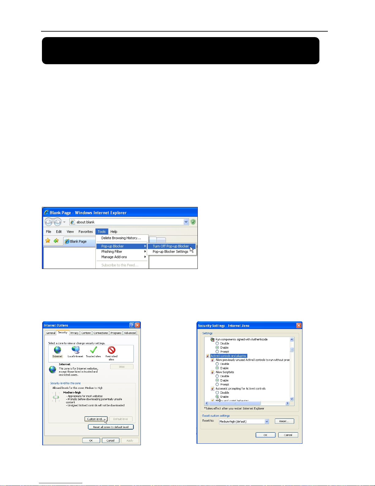
6.1.1. IE Setup
For the first time you are using the IE to access the DVR, you need to modify your browser controls
Take IE 7 for example to demonstrate how to modify your browser controls:
1. Turn OFF “Pop Up Blocker”
Go to Tools Blocker, and then select “Turn Off Pop-up Blocker”.
2. Access & Enable all ActiveX Controls
Go to “Tools” “Internet Options”
“Security” tab, then click “Custom
level…” button.
On this page scroll down to the ActiveX
Controls and Plug Ins, and set all to
either PROMPT or ENABLE.
Page 30

27
Warning! It is strongly recommended to return all Internet Explorer Security to its default settings
after the ActiveX Control has been installed. Enabling all ActiveX controls put your computer at risk
of being attacked by computer virus.
6.1.2. Connect to DVR
To connect to the DVR from a remote computer, you would then open an Internet Explorer browser
window and enter the Internet IP of your router that you received by going to www.myipaddress.com.
If you get an error message “Program cannot load because the Publisher is unknown” or the program
is unsigned, then go to Internet Explorer --> Tools --> Internet Options, then click on the ADVANCED
tab on the top right. This will open the window in, scroll down to “Security”, and select on the options
to “Allow software to run or install even if the signature is invalid”, and “Allow Active Content to Run
Files on My Computer”.
Open Internet Explorer and enter the IP Address or DDNS address of your DVR. A pop-up will ask
you to install an ActiveX (plug-in) to your computer. Please confirm the download and install the
software.
Reminder: If the ActiveX (plug-in) is not downloaded successfully, please check if your browser’s
safety level or firewall setting is set properly (as stated above). Please also make sure all of the setup
of your modem or router is setup properly.
6.1.2.1. IE Plug-in & Netviewer Interface
Open the DVR IP address or DDNS
domain name with IE, or run the Netviewer
software, the LOGIN interface will load.
Input the login information, and then press
LOGIN button.
The default password is null.
After successfully Logged in, system will
open the live display interface and connect
to audio/video feed automatically.
You will be able to see the live images
transmitting from DVR.
Page 31

28
6.1.3 Control Network Access
6.1.3.1 Live
1. On / Off Live display [ ]: When the live display status is “On”, clicking the button to close live
display. When the live display status is “Off”, clicking the button to open live display.
2. Capture [ ]: Capture Screen image and save to PC as *bmp image.
3. Recording [ ]: Operate DVR recording remotely
4. Channel display [ ]: The icons stand for Single Channel display, Quad Channel
display, 3x3 Channel display and 4x4 Channel display respectively.
5. Volume control [
]: Click or slide the control bar to adjust sound volume.
6.1.3.2. Setup
Click “SETUP” on the top menu bar to set DVR system configuration. You can set “Recording Mode”,
“Alarm Mode”, “PTZ Control”, “Network Setting”, “System Setting” and check “Host Info” here.
Please refer to chapters 5 about how to set the DVR system configuration mentioned above.
6.1.3.3. Replay
This option allows you to playback
recordings remotely.
1. Select the day, channel and type
then proceed searching and reload.
2. Select any event from search
result list to playback.
Play: Play and Pause
Stop: stop playing recording
F.F.: fast forward playback recording
Slow: slow playback recording
Next Frame: play frame by frame
264 TO AVI button: convert file from H.264 format to AVI format
6.1.3.4. Convert 264 file to AVI file
The native format of the backup files is H.264, you can convert H.264 format into AVI format by
clicking the key of 264 to AVI.
1. Click the “264 TO AVI” button, the AVI Convert window will open.
2. Determine the source H.264 file & the destination to save the avi file.
3. Click CONVERT. File conversion begins. The progress bar indicates the status of the conversion.
4. Click OK in the confirmation window.
Page 32

29
6.1.3.5. Remote Backup
You can backup recorded video files from DVR to your PC using the Replay menu in the remote
surveillance software.
To backup files remotely:
1. Click REPLAY at the top of the main screen.
2. Select a date on the calendar and click RELOAD.
3. Double-click a file from the File List to begin playback.
4. Click BACKUP. Backup begins to C:/DVR/[ip address]/Backup
NOTE: If you playback a file, you must wait for the file to load before backing it up, otherwise you
may receive an error message
When file backup is complete, click OK in the confirmation window. The confirmation window show
the save path of the backup file. The backup files are saved as .264 files.
6.1.3.6. PTZ Control
1. PTZ direction control: Control PTZ moving direction
2. Zoom, Focus and Iris Control: control direction, zoom, focus and iris of PTZ.
3. Presetting bit Control
CUR: display current presetting bit or input a presetting bit you would like to fix at according to the
edit box.
Load: Load one previous setting you have saved last time.
Save: Save setting.
Set: Set presetting bit parameter
GOTO: on the preview mode, please input a setting for presetting bit no and click “GOTO” button to
preview the setting.
Clean: clear presetting bit setting
Cruise: control cruise status (including on and off).
6.1.3.7. Logout
Log out the system.
Page 33

30
6.1.3.8. Playback Local File with Netviewer
Run the Netviewer software, you will see the OFFLINE button displayed on the Login interface.
Press this button to enter local file playback mode.
Press the ADD button to add backup H.264 files or folder saved in your computer, you will see the
files will be listed in the queue window, select a file then press PLAYFILE button to play.
Page 34

31
6.2 Mobile Phones Access
This function allows you to view 1 channel live image at the same time with your mobile phone.
The DVR is currently compatible with mobile phones running Windows® Mobile, Symbian® S60
3rd/5th Edition operating systems, iPhones® and Blackberry® on GPRS and/or 3G networks.
6.2.1 Mobile Setup
Before you can view the live image from your DVR with compatible mobile phones, you need to set
the settings first. Please also make sure your DVR has well connected to Internet.
Go to MAIN MENU DEVICIE MOBILE, config the mobile phone login settings
6.2.1.1. Install & Operate Mobile Client in Windows® Mobile Phones
1. Install the webcam program that is included on the supplied CD by copying the
“window_mobile.CAB” file to the mobile phone. You can do this by attaching the mobile phone to a
computer and copying the file from the CD to the phone.
2. Click the windows mobile folder and choose the file “window_mobile”. Select the file which will
open the window. The file is generally default to save to the Device’s built-in memory, but you can
choose to save it to Storage Card.
USER NAME: is the user name to enter when
logging into the DVR.
USER PASSWORD: is the password to enter
when logging into the DVR.
SERVER PORT: Mobile monitoring port.
Setting range is between 1024 and 65535. Please
note that the server port number must be
different from the network ports you have
appointed in the NETWORK settings.
NOTE: You also need to forward this port at
the virtual server o
p
tion of your router.
Page 35

32
3. Choose storage location and click “Install” to start the installation.
4. After installation finishes, click the icon named window mobile to run the program. This will
display the program screen.
5. Click the “Setting” button to enter the Setting menu.
User name: same as user name setup in DVR MOBILE setup
Password: same as password setup in DVR MOBILE setup
Server: DVR’s public IP address or DDNS domain name
Web port: Same as the Server Port you setup in DVR MOBILE setup
Channel: Select the channel you want to monitor and click “OK” to display the screen to start viewing
the live image.
6. To stop viewing the live video, click the “Disconnect” button or click the “Setting” button to modify
the settings.
Function of Buttons under the video image from left to right: PTZ control (Left, Right, Up and Down),
area select (Zoom out and Zoom in), Focus (Add “+” and deduct “-”) and Iris (Add “+” and deduct “-”)
and Snap to capture screen image.
Page 36

33
6.2.1.2. Install & Operate Mobile Client in Symbian® Phones
1. Install the webcam program that is included on the supplied CD by copying the “Symban_3.0.sisx”
(Symbian 3.0 version) or “Symbian_5.0.sis” (Symbian 5.0 version) file to the mobile phone. You can
do this by attaching the mobile phone to a computer and copying the file from the CD to the phone.
2. Select the Symbian_3.0/Symbian_5.0 icon in this window to install it.
3. After the phone finishes copying the file, it will ask for permission to install the program. Select
“Yes” to start the installation.
``
4. Click the “Continue” button on the information box displaying the program and current version.
5. Select the location of where you want to install the program, to phone memory or to the memory
card, and then click “Select”.
Page 37

34
6. Click “Continue” and wait for the program to install.
5. Once the installation is complete, go to the Applications folder and select the “Symbian_5.0”
program, and click “Open” to display the settings menu.
Default Access Point:Input the access point. System default for the access point is GPRS connection.
Server Address: DVR’s public IP address or DDNS domain name
Server Port:Same as the Server Port you set in the DVR under section 5.2.10.4.
User name: same as user name setup in DVR MOBILE setup
Password: same as password setup in DVR MOBILE setup
Web port: Same as the Server Port you setup in DVR MOBILE setup
Channel: Select the channel you want to monitor and click “DONE” to display the screen to start
viewing the live image.
Channel select, PTZ control, Zoom in/out, Focus and Iris
Page 38

35
6.2.1.3. Install & Operate Mobile Client in iPhone®
Step 1: Download iTunes
Visit Apple website http://www.apple.com/itunes/ to download & install the iTunes.
Step 2: Download & install surveillance software “Aplayer”
2.1 Register iTunes Store
2.1.1 Run the installed iTunes, you might need to create an account to visit iTunes store firstly. Move
to the menu “Store”, and click the option “Create Account”.
2.1.2 Continue
Page 39

36
2.1.3 Select & continue
2.1.4 Fill in your personal info & continue.
Please note that the options of Payment Method are different from different regions, please
select another payment method. Don’t worry, “Aplayer” is free software & you don’t need to
pay for it.
2.1.5 Finished the register, and go to your email box to verify your account.
**
Page 40

37
Click the link included in the email message.
It will connect to the iTunes store and turn to iTunes interface.
Sign in your account.
The register of your iTunes store account has been done.
Page 41

38
2.2 Authorize Computer
You need to authorize your computer with the registered ID.
Move to the menu “Store”, and click the option “Authorize Computer”.
Input your registered ID & password, then click Authorize button.
2.3 Download & install “Aplayer” into your iPhone
2.3.1 Click iTunes Store(1), then input “aplayer” into the search bar(2) on the right upper corner and
press Enter.
You will find the Aplayer icon displayed as below.
1
Page 42

39
2.3.2 Click the icon and it will turn to the download page. Click the “GET APP” button to download
the file.
You will find the downloaded file on the directory of Application
2.3.3 Connect your iPhone to the computer, you will find your Device displayed on the left sidebar.
Select the DEVICES ID(1), and then click “Applications” option(2). Select the “Sync Applications” &
“Aplayer” (3) and then click “Sync” button(4).
2
4
Page 43

40
The devices ID is different from different iPhones.
After finishing the sync, you will find the Aplayer Icon on your iPhone
Step 3: Setup & run “Aplayer”
Main interface of Aplayer & function keys:
. Direction keys of PTZ controlⅠ
. Zoom+ & ZoomⅡ -
. Focus+ & FocusⅢ -
. Iris+ & IrisⅣ -
. Channel selection keysⅤ
. Play & PauseⅥ
. SnapshotⅦ
. Full screenⅧ
. Next group of channelsⅨ
. SetupⅩ
3.1 Access information setup
Turn into setup menu, and fill in the information according to your DVR Mobile settings.
Press Play button to start mobile surveillance.
Press channel selection keys to switch camera picture.
Server IP: input the IP address or domain name to visit your DVR
Port: same with the server port you have set in your DVR mobile settings
User ID: same with the user name you have set in your DVR mobile
settings
Password: same with user password you have set in your DVR mobile
settings
After finishing the settings, press “Back” button to the main interface.
ⅠⅡⅢⅣⅤ
Ⅵ
Ⅶ Ⅷ Ⅸ Ⅹ
Page 44

41
Model KG-SHA104 ( 4CH ) KG-SHA108 ( 8CH )
Video Compression H.264
Video System NTSC / PAL
Operation System Linux
Video Input /
Output
BNC 4-channel / VGA 1-channel &
BNC 2-channel
BNC 8-channel / VGA 1-channel & BNC
2-channel
Audio Input / Output
RCA 1-channel /
1-channel
Audio Compression 8kHz*16bit ADPCM
Display Frame Rate PAL: 100 fps / NTSC: 120 fps PAL: 200fps / NTSC: 240fps
Playback Resolution
PAL: CIF(352x288),
HD1(704x288), D1(704x576)
NTSC: CIF(352x240),
HD1(704x240), D1(704x480)
PAL: CIF(352x288)
NTSC: CIF(352x240)
Recording Frame Rate
PAL: 25fps@D1, 50fps@HD1,
100fps@CIF
NTSC: 30fps@D1, 60fps@HD1,
120fps@CIF
PAL: 200fps@CIF
NTSC: 240fps@CIF
Recording Mode Always / schedule (motion detection/manual)
Recording Pack Time 15/30/45/60mins file time selectable
HDD Interface One fixed HDD rack, supports up to 2TB SATA HDD
Network Interface RJ45, 10M/100M
Network Protocol Support TCP/IP, DHCP,DDNS, PPPoE
Network Function Support to live view with IE (Internet Explorer) & with mobile phone
USB2.0 USB mouse, USB disk (backup, upgrade)
Playback
Local: Playback 4 channels at the same
time
network: 1-channel
Local & network: Playback 1 channel @
CIF at the same time
Playback Search Date/ time, file list
Playback Mode PLAY / SLOW / FWD / Frame by frame
Backup Backup via USB flash disk, USB HDD disk, USB CD/DVD-RW & Network
PTZ Control Built-in RS485, support PELCO-P & PELCO-D
Alarm Mode Motion Detection, video loss, HDD loss, HDD full, Email
Power Supply DC 12V/3A (power adaptor included)
Power consumption
10-15 W (exclude HDD)
Working Temperature
50°F to 104°F (10℃ to 40℃)
Dimension 300*224*55mm (WxDxH)
Weight Approximate 2.85kg Approximate 2.9kg
Chapter 7. Specifications
Page 45
42
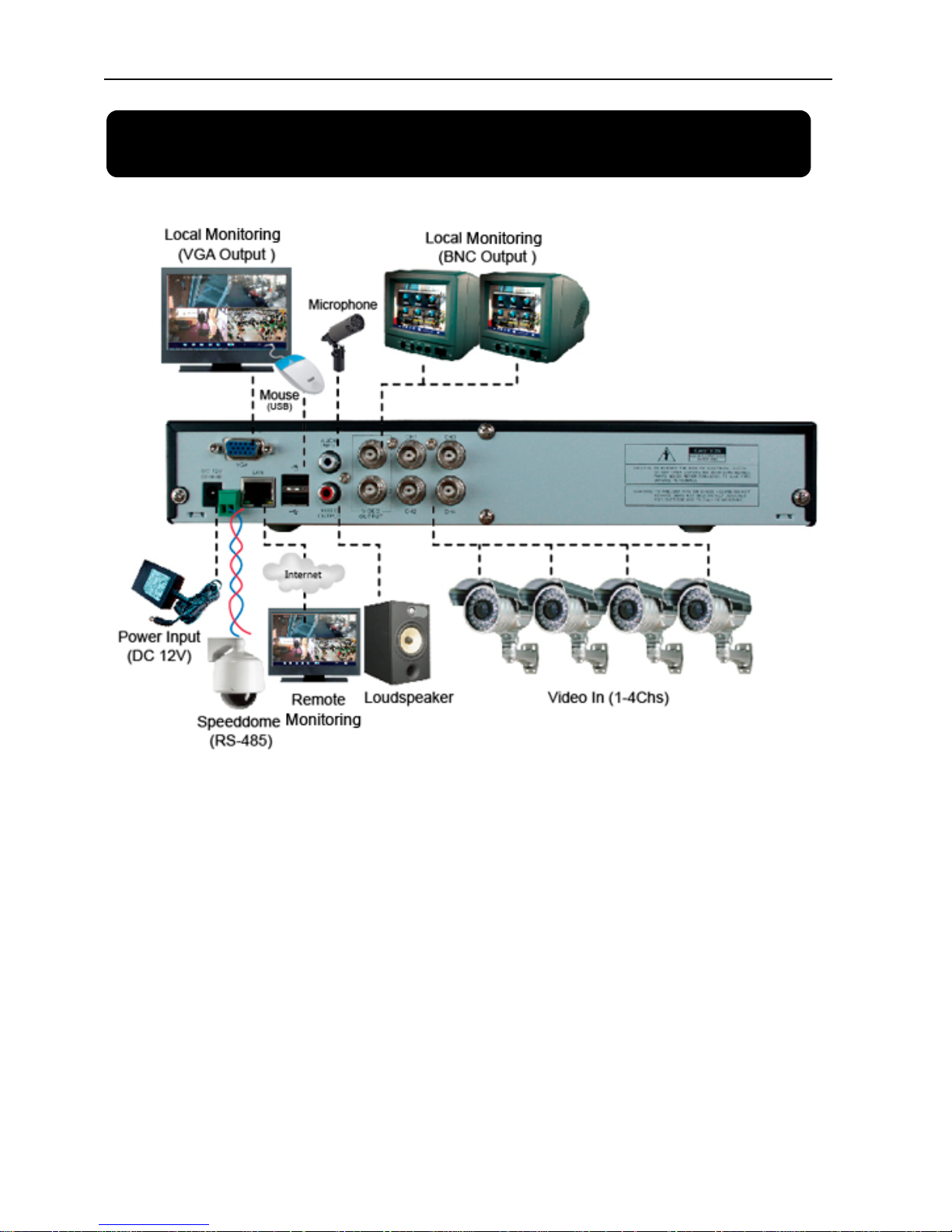
Chapter 8. System connection Configuration
4Channel DVR
Page 46

43
8Channel DVR
Page 47

44
Chapter 9. Appendix
9.1 Operation Function Table
Type Title Description
Page
Time setting Setting system date, time and format and day-light saving time setting 20
Language Select Setting system language 22
CH Setting
Setting CH title and position; adjusting image color parameter value; setting CH display to
ON / Off and time display/recording time overlaying to On/Off.
11
Rec. Setting Setting image quality, resolution, volume, recording mode an pack time 13
Rec. Search Time based search, channel based search and rec. mode based search. 15
Rec. Playback Specified time playback, scheduled playback, file list playback 15
Playback mode Play, play frame by frame, multi-speed forward and multi-speed rewind 15
File backup USB flash disk and removable HDD backup 15
HDD Manage Check HDD status, usage space, setting HDD auto-overwrite 16
Principle
Setting
Video Setting Adjust VGA resolution, select video system 22
User password Setting or modifying user password 21
Alarm setting
Setting HDD lost, HDD space, video loss, alarm management and Email alarm
17
Motion detection
Setting on/off status of MD; select sensitivity and setting motion detection
area.
19
PTZ control Selecting CH and setting PTZ protocol, baud rate and PTZ address for the CH 19
Mobile Monitor Setting user name, password and server port. 31
Advanced
Setting
System
Maintenance
Setting system auto maintenance, maintenance time regularly, system upgrade,
ex-factory default value recovery and manual restart system
22
Network
Setting
Network and Port
setting
Selecting network mode and setting net-viewer port, web port, DNS and
DDNS parameters.
23
Live display Real time video input remotely 25
Remote playback Check local recording history via network 28
PTZ control Remotely control PTZ camera, position, focus, zoom and iris etc. 29
parameter set of
DVR remotely
Setting local CH display, recording, alarm, PTZ control parameter value via
network
28
Network
Function
Network download
Backup recording file via network 29
System info Check device model, software version and MAC address 22
Auxiliary
function
()
In addition to illustrating picture, Parenthesis generally indicate optional
parameter value of previous menu.
Confirm The button allows you save the modification of parameter value.
Recover default The button allows you recover default value of current menu or system
Exit The button allows you exit the current menu.
Menu
button
Next
On multi-channel mode, the button allows you check or modify other channel’s parameter;
on [File list] mode, the button allows you display next page.
Page 48

45
9.2. Recording Alarm setting
Please refer the below matrix: “⊥” stand for “only alarm but no recording”; “AMR” stand for “alarm
recording”; “NLR” stand for “normal recording”; and “NOR” stand for “ no recording”. Once alarm is triggered,
alarm icon will occur, and when many alarms are triggered, alarm remarks will occur on the screen.
Recording Mode
Timing recording
Recording alarm setting Alarm icon
Recording after
power on
AMR NLR NOR
Manuel Recording
MD alarm AMR AMR NLR ⊥ NLR
HDD loss, HDD space full ⊥ ⊥ ⊥ ⊥ ⊥
Alarm
mode
Video Loss Video Loss ⊥ ⊥ ⊥ ⊥ ⊥
List 9-2
When DVR is in recording mode, [
] icon or [ ] icon will appear on the screen. But when there is [ ] icons
on the screen it indicates a motion alarm was triggered. When [
] icon appears on the screen, that mean a hard
drive alarm has occurred.
9.3. Troubleshooting
1. Q: What can I do if the system does not detect the HDD?
A: Check the data and power cables and make sure they are securely connected.
2. Q: We have changed the password but do not remember the new password, how can we access the system?
A: If you forget system password, enter 0800808 into the password field to reset the password
3. Q: We are not getting any video signal on the DVR, what is wrong?
A: Check to make sure the cables are securely connected to the BNC ports on the DVR. You can also try another
cable to make sure there is not a problem with the cable. Make sure you have selected the correct video format for
your country (NTSC or PAL), is the USA we use NTSC.
4. Q: Can the DVR have problems if it gets too hot, how can I prevent this?
A: The DVR has a fan to help it dissipate heat while it is working. Please place the DVR in a place where there
is good air circulation and away from high temperatures to increase stability and life of the DVR.
5. Q: My remote control does not work when the DVR is in Live mode but the front panel buttons are working,
what is wrong?
A: Make sure nothing is blocking the LED on the remote or the receiver on the DVR, if both are ok, check the
batteries.
6. Q: Can I use the hard drive from my PC in the DVR?
A: You can if the hard drive is the same type and the size is supported by the DVR. If you install it in the DVR it
will be formatted for use in the DVR and the PC will not be able to read it.
7. Q: Do I have to stop recording to playback files on the DVR?
A: No you do not have to stop recording, the DVR will support both functions at the same time.
8. Q: Can I erase files from the hard drive of the DVR?
A: You can not erase individual file, you would need to format the hard drive which will erase all of the files
9. Q: Why can’t I log-in to the Net-viewer program?
A: Please verify that the Net mode is correct, the cable to the RJ-45 port is well connected to the DVR and the
router, and that you are using the correct password.
10. Q: We have attached a PTZ camera but can not control it, what is wrong?
A: Verify that the Protocol, baud rate, address, and other settings on the PTZ camera match the settings you have
put into the DVR. Make sure the data cables are attached firmly to the RS485 port on the DVR.
11. Q: Why does the Buzzer keep sounding?
A: Please check to see if motion detection is on and the system has detected motion, make sure the hard drive is
being detected and has sufficient space available and that none of your cameras have lost video. You can turn off
the buzzer in the Alarm setup option.
Page 49

46
9.4. Email server check list(The below info only for your ref.)
(Web site)
Email address
Sender server(25) Receiver server(110)
@yahoo.com.tw smtp.mail.yahoo.com.tw pop.mail.yahoo.com.tw
www.yahoo.com
@yahoo.com smtp.mail.yahoo.com pop.mail.yahoo.com
www.google.com @gmail.com smtp.gmail.com(465/587) pop.gmail.com(995)
List 9-3
9.5. Usage Maintenance
1. Please make sure DVR keep away from heating source.
2. Clean the internal dust regularly, keep DVR aeration well and be easy to heat dissipate.
3. Please not plug in RS-232 and RS-485 when power is on to avoid any damage to the port.
4. Please check the HDD cable and data cable to avoid the cable aging.
5. Please avoid other electronics device interfere video/audio signal of DVR a.s.a.p., or static electricity and
induced voltage damage to DVR.
6. Suggest user replace BNC cable regularly to keep signal input stable.
Page 50

The material in this document is the intellectual property of our
department .
No part of this manual may be reproduced, copied, translated,
transmitted, or published in any form or by any means without our
department prior written permission.
Our products are under continual improvement and we reserve the right to
make changes without notice. But no gua ran te e is given as to the correctness
of its conten ts .
We d o not undertake any responsibility for the harms cause by using our
product.
The model of the product s in the user's manual on ly for re cogni tion, bu t
these names also perhaps are belong to other company's registered
trademar k or the copyright.
The product picture may differ from the actual product, only for your
reference. The accessories will probably be different according to the
differ ent sell ing areas. For details of accesso ries, please refer to your local
distribut or.
ٛ
ٛ
ٛ
ٛ
ٛ
Copyright reserved
 Loading...