

Page 1
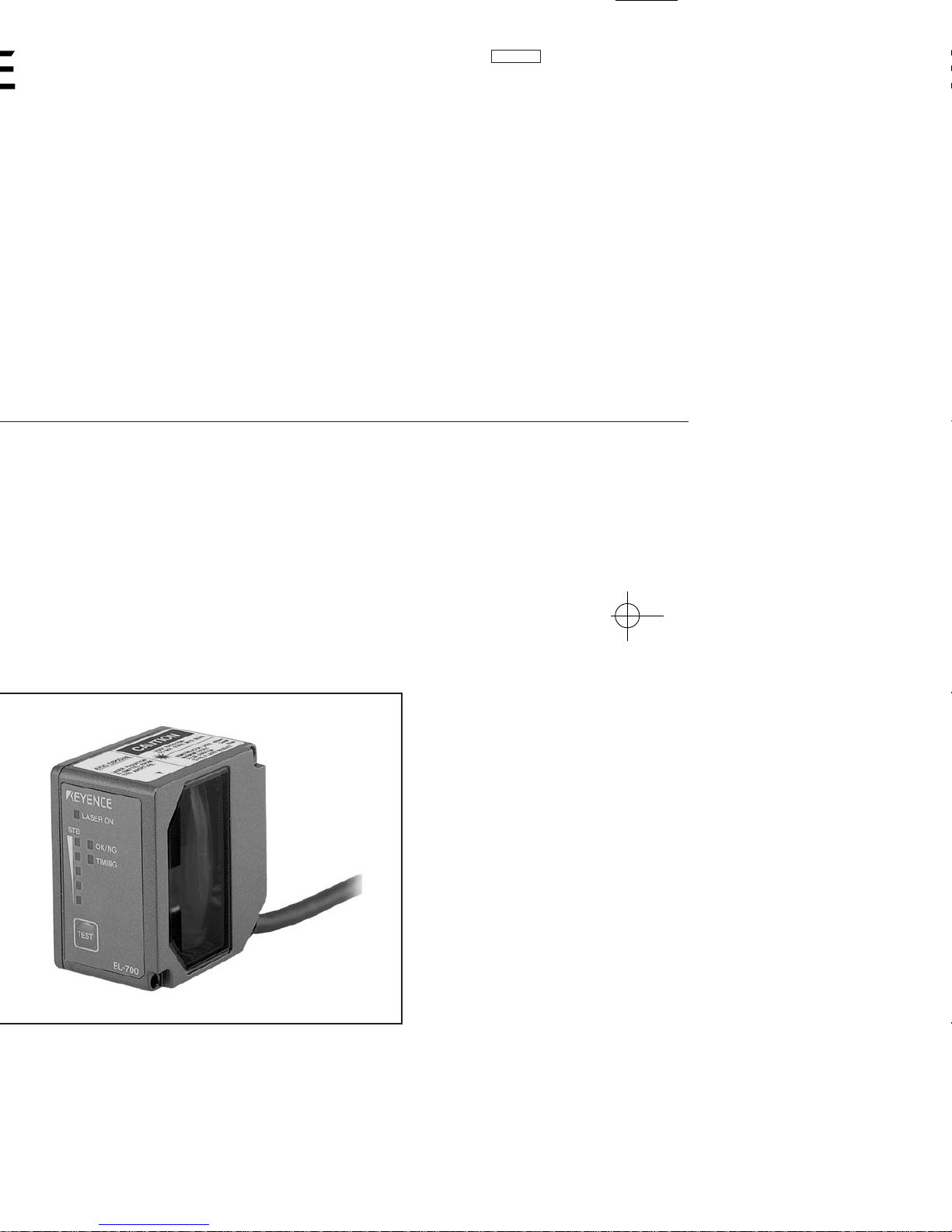
96M1126
Page 2

Safety Precautions
This instruction manual describes the operation and function of the BL-700. Read
this manual carefully to ensure safe use and maximum performance from your BL-
700. The BL-700 series uses a semiconductor laser as light source. Before using
the product, see "Laser Safety Precautions" on page 1 to learn the safe and correct
method of using the BL-700 series.
Symbols
The following symbols alert you to important messages. Be sure to read these
messages carefully.
Failure to follow instruction may lead to injury. (electric
shock, burn, etc.)
Failure to follow instructions may lead to product damage.
Provides additional information on proper operation.
General Precautions
• At startup and during operation, be sure to monitor the functions and performance of the BL-700.
• We recommend that you take substantial safety measures to avoid any damage
in the event a problem occurs.
• Do not open or modify the BL-700 or use it in any way other than described in
the specifications.
• When the BL-700 is used in combination with other instruments, functions and
performance may be degraded, depending on operating conditions and the
surrounding environment.
• Do not use the BL-700 for the purpose of protecting the human body.
WARNING
CAUTION
Note:
i
Page 3

ii
Warnings and Cautions Specific to the BL-700
• The BL-700 uses a 5 VDC power supply. Using a different voltage level
may damage the unit.
When using the KEYENCE power supply unit BL-U1, BL-U2, N-42 or N-48,
select the voltage level which can be supplied by the power supply unit. If
a nonconforming power supply is connected, the BL-700 may be damaged.
• The BL-700 is a precision instrument. If the unit is dropped or shocked, it
may be damaged. Take due consideration when transporting or installing
the unit.
• Do not hold the cables when carrying the units. The units may hit each
other and become damaged.
• Before installing the BL-700, read “2.4 Installation” of this manual carefully to
select a suitable installation site.
• You cannot perform any operation for 5 seconds after turning ON the BL-700.
During this time, the motor rotation stabilizes. Wait for a while after turning ON
the BL-700, then start reading or another operation.
• At shipment, the protective seals are affixed to the transmitter and receiver to
avoid fingerprints when mounting the unit. Be sure to remove the seals before
use.
• Do not allow water, oil or dust to adhere to the transmitter and receiver. Adhesion of these materials may cause a reading error. If the surface is contaminated, gently wipe it with a soft cloth moistened with alcohol.
CAUTION
Incorrect
Incorrect
96M1126
Page 4

iii
Package Contents List
The package contains the following components. Be sure to check the package
contents against the checklist before use.
■ BL-700 package
• BL-700 unit ................................................................................................ 1
• Mounting bracket ......................................................................................1
• Mounting screw ......................................................................................... 2
• Insulating spacer ....................................................................................... 4
• Washer ...................................................................................................... 4
• Laser warning label (Japanese/English/German) ............................... 1 set
■ BL-U1 package
• BL-U1 unit .................................................................................................1
■ BL-U2 package
• BL-U2 unit .................................................................................................1
• D-sub 9-pin connector, connector case .................................................... 1
• Instruction manual ..................................................................................... 1
■ N-42 package
• N-42 unit ...................................................................................................1
• Instruction manual ..................................................................................... 1
■ Setup software, user’s manual (BL-H1WE)
• Setup software (3.5-inch, 1.44 MB) ..........................................................1
• User’s manual (this manual) ..................................................................... 1
Page 5
iv
BL Series Lineup
■ Laser bar code reader
■ Power supply
■ Other options
• N-400: Multi-drop controller
Used as the master unit when multi-drop linking with the BL series.
• BL-P1E: Handheld programmer specially designed for the BL series.
Used when changing the BL-series or N-400 settings.
• OP-22149 : D-sub 25-pin (male) — D-sub 25-pin (male) RS-232C cross cable
Connects the BL-U1 to the PC (use with OP-25057).
• OP-25057 : D-sub 25-pin — D-sub 9-pin conversion connector
Used in conjunction with OP-22149 when connecting the BL-U1 to
the DOS PC.
• OP-27937: D-sub 9-pin — D-sub 9-pin RS-232C cross cable
Connects the BL-U2 to the DOS PC.
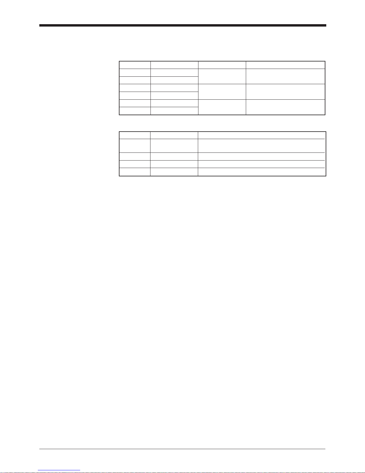
Model Scanning method Readable bar width Reading distance
BL-700 Single 0.15 to 1.0 mm 160 to 370 mm
BL-701 Raster (When narrow width is 0.5 mm)
BL-740 Single 0.25 to 2.0 mm 150 to 750 mm
BL-741 Raster (When narrow width is 1.0 mm)
BL-780 Single 0.32 to 2.0 mm 200 to 1200 mm
BL-781 Raster (When narrow width is 2.0 mm)
Model Supply voltage Interface
BL-U1 100 to 240 VAC RS-232C, RS-422A, RS-485 multi-drop
* Select one of these.
BL-U2 24 VDC RS-232C
N-42 24 VDC RS-422A
N-48 24 VDC RS-485 multi-drop
Page 6
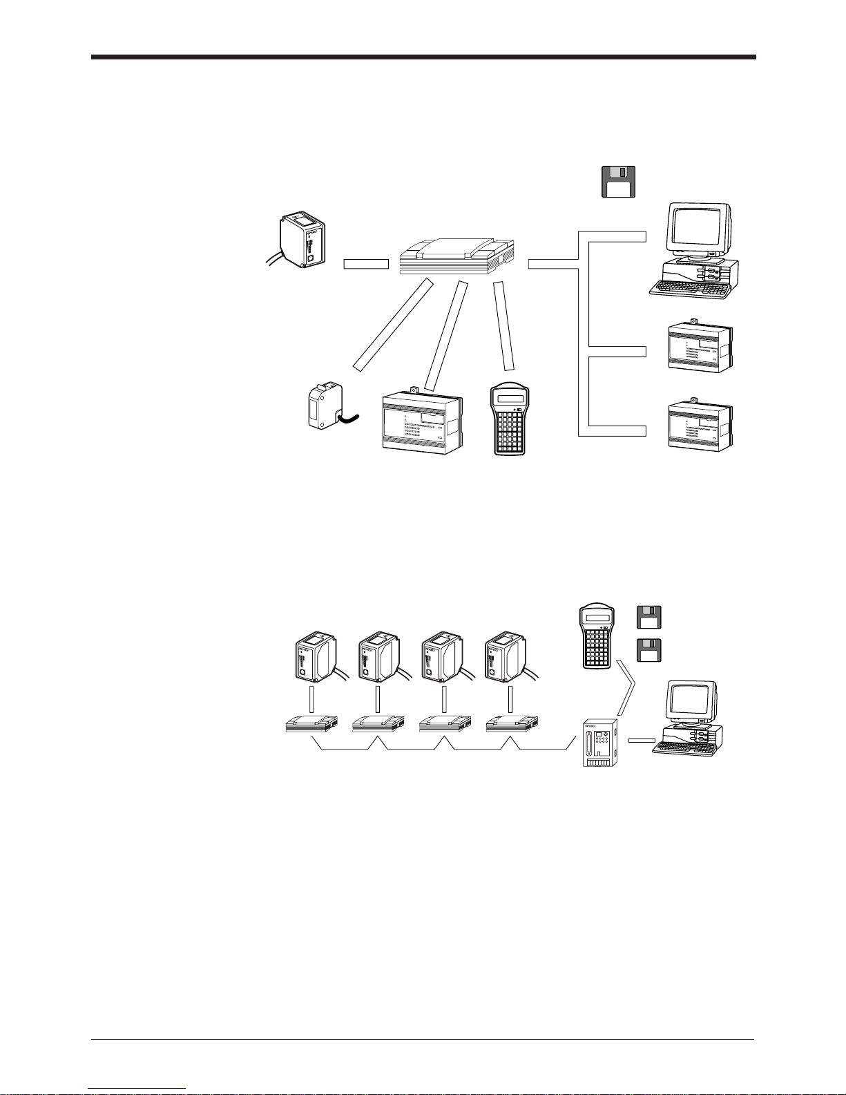
System Configuration
■ When using RS-232C or RS-422A
BL-700
RS-232C
Serial
communication
Serial
communication
BL-U1, BL-U2, N-42
Power supply unit
RS-422A
OK/NG
output
IBM PC/AT
or compatible
Setup software
for BL series
(BL-H1WE)
Windows version
Trigger input
PLC etc. Handheld
programmer BL-P1E
PLC (Link unit)
PLC (RS-232C/422A unit)
PLC link
Timing sensor
LASER ON
STB
OK/NG
TIMING
TEST
BL-700
* Use the BL setup software or the handheld programmer BL-P1E to set the BL
series.
BL-700
Power supply unit
BL-U1, N-48
RS-485
Multi-drop
controller N-400
Handheld programmer
BL-P1E
BL setup software
Windows version
N-400 setup software
Windows version
RS-232C
PC
LASER ON
STB
OK/NG
TIMING
TEST
B
L-70
0
LASER ON
STB
OK/NG
TIMING
TEST
B
L-70
0
LASER ON
STB
OK/NG
TIMING
TEST
B
L-70
0
LASER ON
STB
OK/NG
TIMING
TEST
B
L-70
0
■ When using the RS-485 multi-drop link
* Use the N-400 setup software or handheld programmer BL-P1E to set the multi-
drop controller N-400.
* For system configuration for the multi-drop link, see the “N-400 User’s Manual”.
Also, for connection and operation of the multi-drop link controller, see the “N400 User’s Manual”. The BL-700 User’s Manual does not cover these subjects.
v
Page 7

Parts and Functions
BL-700
LASER ON
STB
OK/NG
TIMING
TEST
BL-700
1LASER ON LED
2STABILITY LED
3OK/NG LED
4TIMING LED
5TEST switch
6Transmitter/receiver
7 Cable
No. Name Function
1 LASER ON LED Lit when laser beams are emitted.
2 STABILITY LED Displays the reading stability and the BL-700 operating status.
➮
See P. 64 to P. 65
3 OK/NG LED • When OK output is ON: The green LED lights.
• When NG output is ON: The red LED lights.
4 TIMING LED Lit when trigger input is ON.
5 TEST SWITCH This switch allows the following operations:
• Start the test mode.
• Pressing the switch once reads the bar code once.
• Sets the communication protocol to the initial values when
sending the settings.
➮
See P.75
• Reset the error status.
➮
See P.45
6 Transmitter/receiver Window to emit laser beams and receive reflected lights.
7 Cable Cable length is 1.8 m.
vi
Page 8
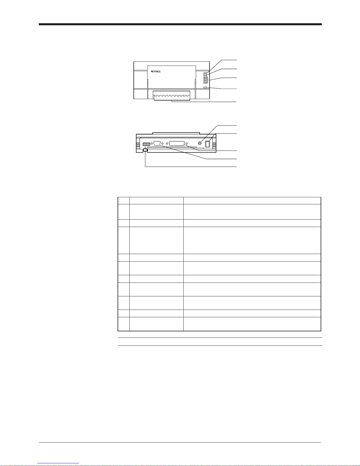
No. Name Function
1 OK/NG LED • When OK output is ON: The green LED lights.
• When NG output is ON: The red LED lights.
2 TIMING LED Lit when trigger input is ON.
3 • Allows you to monitor the communication status of the
RS-232C port.
• The SD, RD, RS and CS indicators are provided in this
order from the top.
4 POWER LED Lit when power is ON.
5 I/O terminal block Includes the trigger input terminal, OK/NG output terminals,
RS-422A terminal and RS-485 terminal.
6 Power switch Turns the power ON/OFF.
7 Use a 100 to 240 VAC (50/60 Hz) power supply.
8 RS-232C port Connect a personal computer to this port. This port is
unused in multi-drop link mode.
9 READER port Connect the BL series to this port.
0 DIP switches Switches the communication port, and turns the terminator
ON/OFF.
Communication status
indicator LEDs
Power supply cable
(2 m)
BL-U1
1 OK/NG LED
2 TIMING LED
3 Communication status indicator
LEDs
4 POWER LED
5 I/O terminal block
6 Power switch
7 Power supply cable (2 m)
8 RS-232C port
9 READER port
0 DIP switches
vii
Note: This product does not comply with EC directives.
Page 9
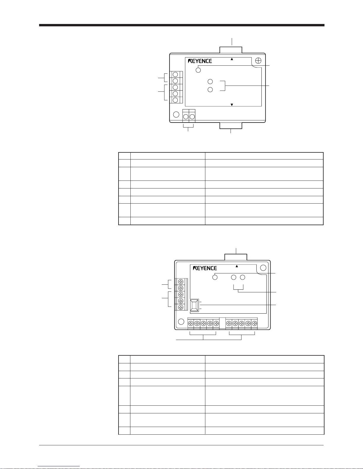
BL-U2
POWER
SD
RD
BL-U2
RS-232C
READER
7 RS-232C port
1 READER port
2 TRIGGER input
terminals
3 OK/NG output
terminals
4 Power supply
terminals
5 POWER LED
6 Communication
status indicator LEDs
5 Terminator switch
1 READER port
4 Power supply terminals
7 POWER LED
6 Communication
status indicator
LEDs
ON
OFF
2 TRIGGER input
terminals
3 OK/NG output
terminals
POWER SD RD
READER
N-42
No. Name Function
1 READER port Connects to a BL series or RS-232C equipment.
2 TRIGGER input terminals Connect to a sensor for trigger input.
3 OK/NG output terminals Output OK/NG signals.
4 Power supply/ interface The 24 VDC power supply terminal and communi-
terminal block cation interface (RS-422A or RS-485) terminal are
provided.
5 Terminator switch Turns ON/OFF the terminator resistor: 100 ).
6 Communication status Indicates the RS-422A or RS-485 communication
status.
7 POWER LED Lights when the power is turned ON
No. Name Function
1 READER port Connects to a BL series bar code reader.
2 TRIGGER Connect to a sensor for input terminals
trigger input.
3 OK/NG output terminals Output OK/NG signals.
4 Power supply terminals Connect to a 24 VDC power supply.
5 POWER LED Turns on when the power is on.
6 Communication status Indicate the communication status of the RS-232C.
indicator LEDs
7 RS-232C port Connects to a personal computer, etc.
viii
Page 10
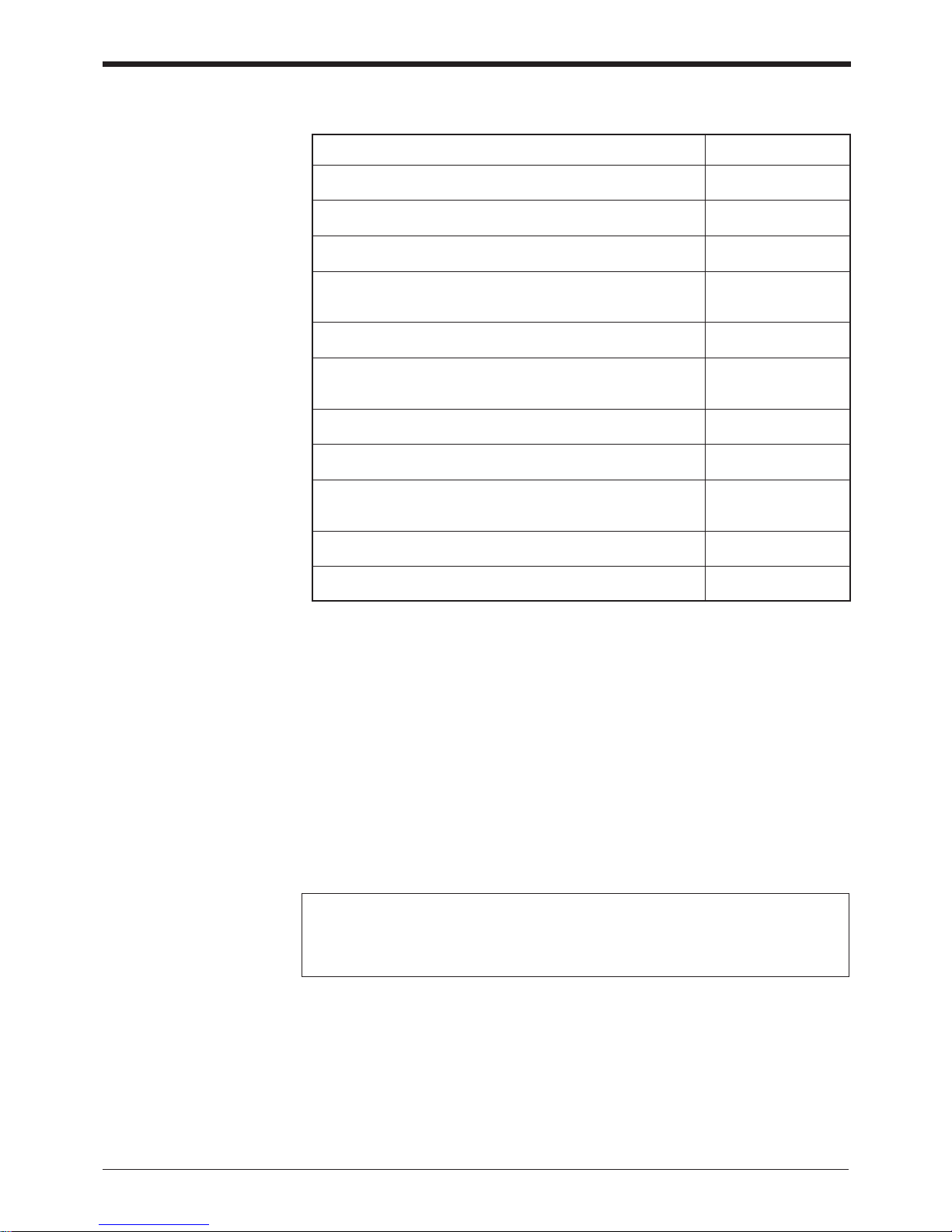
Using the Manual
* This manual uses the expression “BL-700” for the BL-700/701/740/741/780/781
unless otherwise specified.
Purpose Reference page
Turn on the trigger timing or wire the RS-232C cable. P.6 to 24
Mount the bar code reader. P.25 to 29
Perform the simple read test. P.40
Check the test mode reading rate or readout count on the P.81
PC screen.
Change the BL-700 settings using the setup software. P.51 –
Change the BL-700 settings through the handheld programmer See the BL-P1E
BL-P1E. User’s Manual.
Communicate with a PC. P.105 –
Control the BL-700 with the PLC link. P.121 –
Use the BL-700 with the multi-drop link. See the N-400
User’s Manual.
Troubleshooting P.136
PLC link communication setup. P.118
Notice
• No part of this instruction manual may be reprinted or reproduced without the
prior written permission of KEYENCE CORPORATION.
• KEYENCE assumes no responsibility for the contents of this manual. No liability
is assumed for damages resulting from a program created by customers.
• The contents of this manual are subject to change without notice.
• “MS”, “Windows” and “Windows95” are registered trademarks of Microsoft,
U.S.A.
• Other company names and product names are registered or nonregistered
trademarks of respective companies.
ix
Page 11
Contents
Chapter 1 Laser Safety Precautions
1.1 Classification ..........................................................................................2
1.2 Warning Labels ......................................................................................2
1.3 Label Location ........................................................................................3
1.4 Safety Consideration ............................................................................. 4
1.5 Safety Features Provided with the BL-700 Series .............................. 4
Chapter 2 Connection and Installation
2.1 BL-700 connections ............................................................................... 6
2.1.1 Connector pin assignment ........................................................................6
2.1.2 Power supply connections ........................................................................6
2.1.3 Wiring I/O .................................................................................................. 7
2.1.4 RS-232C connection................................................................................. 7
2.2 Connecting BL-U1 and wiring ...............................................................8
2.2.1 Connecting the power supply.................................................................... 8
2.2.2 Connecting the BL-700 .............................................................................8
2.2.3 Setting BL-U1 DIP switches...................................................................... 9
2.2.4 Terminals of I/O terminal block and wiring.............................................. 10
2.2.5 Connecting RS-232C .............................................................................. 11
2.2.6 Wiring the RS-422A ................................................................................14
2.3 Wiring the KEYENCE power supply unit BL-U2/N-42 ....................... 16
2.3.1 Connecting the power supply.................................................................. 16
2.3.2 Connecting the BL-700 to BL-U2/N-42 ...................................................16
2.3.3 Terminals of I/O terminal block and connections .................................... 17
2.3.4 Terminal .................................................................................................. 18
2.3.5 Connecting RS-232C (BL-U2) ................................................................ 18
2.3.6 Connecting the N-42 to RS-422A ........................................................... 21
2.4 Installation ............................................................................................ 23
2.4.1 Operating environment precautions........................................................ 23
2.4.2 Installing the BL-700 Series .................................................................... 25
2.4.3 Installing the BL-U1................................................................................. 27
2.4.4 Installing the BL-U2, N-42....................................................................... 27
x
Page 12

Chapter 3 Functions for Reading Operation
3.1 Read Operation .................................................................................... 30
3.1.1 Scanning method .................................................................................... 30
3.1.2 Data-send mode ..................................................................................... 32
3.2 Read Modes ..........................................................................................33
3.2.1 Single label read mode ...........................................................................33
3.2.2 Multi-label read mode 1 (Multi 1) ............................................................ 33
3.2.3 Multi-label read mode 2 (Multi 2) ............................................................ 34
3.2.4 Multi-label read mode 3 (Multi 3) ............................................................ 35
3.3 Label Orientation Mode........................................................................... 37
3.4 Test Mode ............................................................................................. 38
3.4.1 Reading rate check mode ....................................................................... 38
3.4.2 Tact check mode..................................................................................... 39
3.4.3 Online test mode..................................................................................... 41
3.5 STABILITY LEDs .................................................................................. 42
3.6 Preset Function (Compare with:) .......................................................44
3.6.1 What is the preset function? ................................................................... 44
3.6.2 Wildcard Symbols (“!” and “?”) ...............................................................45
3.7 Additional Information ......................................................................... 46
3.8 Max. Code Length (Designated Digit ) Output Function .................. 48
Chapter 4 Setup Software
4.1 Installing the Setup Software .............................................................. 50
4.1.1 Installing setup software ......................................................................... 50
4.1.2 Installation procedure.............................................................................. 50
4. 2 Setup Software Operating Procedure ................................................ 52
4.2.1 Operating procedure ............................................................................... 52
4.2.2 Description on each setup screen........................................................... 53
4.2.3 Outline of operation................................................................................. 54
4.3 Details of Setup ....................................................................................56
4.3.1 Setup procedure ..................................................................................... 56
4.3.2 Reading/Saving/Printing File................................................................... 69
4.4 Sending/Receiving Settings ................................................................ 73
4.5 Using Monitor .......................................................................................77
4.6 List of Error Messages ........................................................................ 80
4.7 Example of Printing from the Setup Software ................................... 81
xi
Page 13
Chapter 5 Serial Communication
5.1 Serial Communication ......................................................................... 84
5.2 Details on Data Communication ......................................................... 85
5.3 Command Communication .................................................................88
5.3.1 Setup of Direct Control Commands ........................................................88
5.3.2 Details on Parameter Setting Commands............................................... 92
Chapter 6 PLC Link
6.1 PLC Link ............................................................................................. 104
6.1.1 List of PLCs used for PLC link ..............................................................104
6.1.2 Devices used for PLC link..................................................................... 105
6.2 Setting the BL-700 and PLC .............................................................. 106
6.2.1 Setting the BL-700 series...................................................................... 106
6.2.2 Setting the PLC..................................................................................... 106
6.3 Device Assignment ............................................................................ 109
6.4 PLC Link Error ....................................................................................116
6.5 Communication Time ........................................................................ 117
Appendices
Appendix A Specifications .......................................................................120
Appendix A.1 Specifications ..........................................................................120
Appendix A.2 Reading range characteristics (Typical) .................................. 122
Appendix A.3 Angular characteristics (Typical) .............................................125
Appendix B. BL-U1 Specifications ............................................................126
Appendix C. BL-U2, N-42 Specifications .................................................. 127
Appendix D. Dimensions ...........................................................................128
Appendix E. Example Program for Serial Communication .................... 131
Appendix F. Sample Program for the PLC Link ......................................132
Appendix G. Troubleshooting ................................................................... 135
Appendix H. CODE93 Specifications ........................................................ 137
Appendix I. CODE128 Specifications ...................................................... 138
Appendix J. Checksum Calculation Method ........................................... 139
Appendix K. ASCII Code Table ..................................................................141
Appendix L. Setup Parameter List ............................................................142
Appendix M. Default Setting List ............................................................... 145
Chapter 7 Warranty
Warranty ..................................................................................................147
xii
Page 14

xiii
Page 15

Chapter 1
Laser Safety Precautions
1.1 Classification ........................................................................ 2
1.2 Warning Labels ..................................................................... 2
1.3 Label Location ...................................................................... 3
1.4 Safety Consideration ............................................................4
1.5 Safety Features Provided with the BL-700 Series .............4
Page 16
Chapter 1 Laser Safety Precautions
1
2
1.1 Classification
Model BL-700/701 BL-740/741 BL-780/781
FDA (CDRH) Class II
IEC/EN 60825-1: 1993 + A2: 2001 Class 2
DIN EN 60825-1 2001 Klasse 2
1.2 Warning Labels
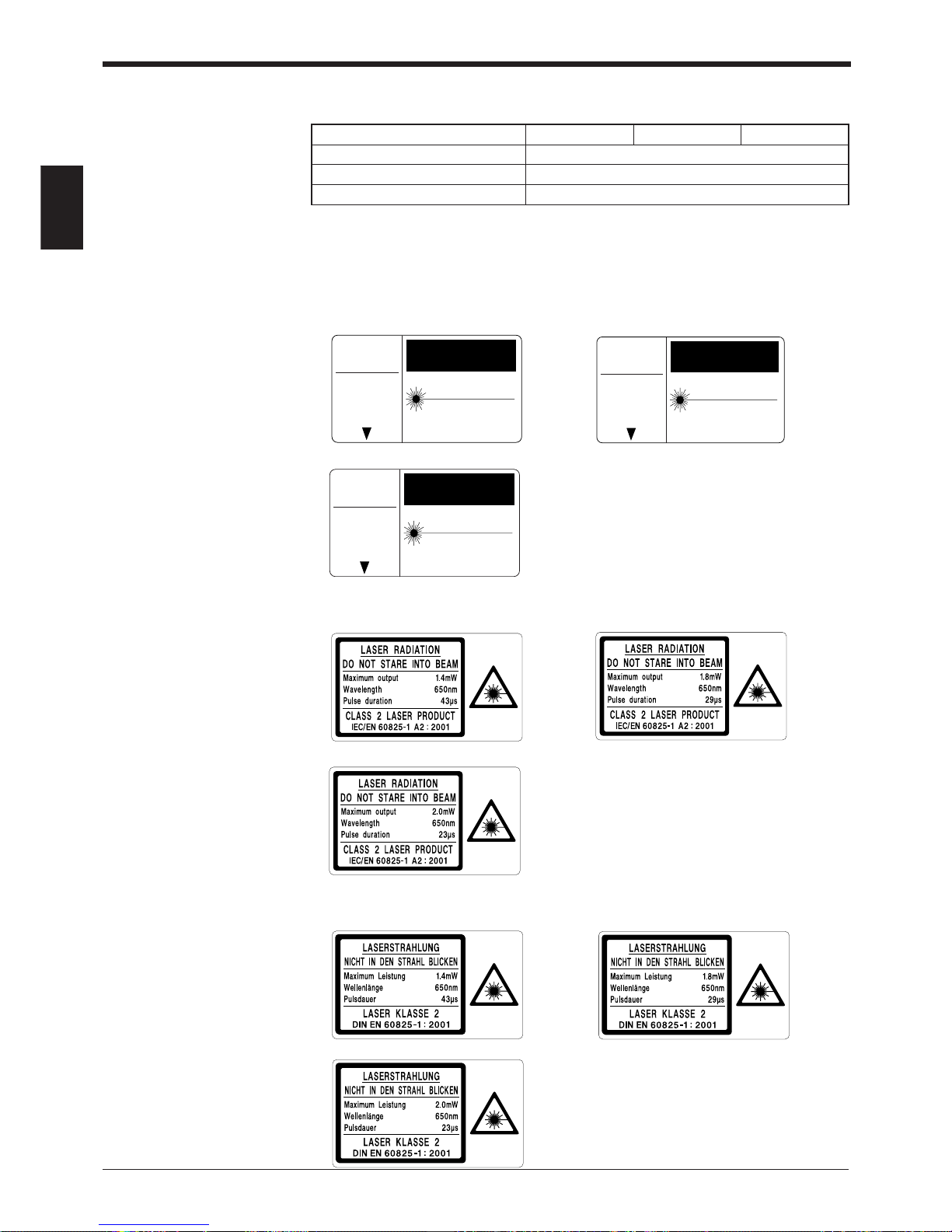
1) Warning labels
■ FDA
BL-700/701 BL-740/741
BL-780/781
■ IEC
BL-700/701 BL-740/741
BL-780/781
■ DIN
BL-700/701 BL-740/741
BL-780/781
LASER RADIATIONDO NOT STARE INTO BEAM
SEMICONDUCTOR LASER 650nm
MAXIMUM OUTPUT 1.4mW
PULSED RADIATION 91 µm
CLASS II LASER PRODUCT
CAUTION
AVOID EXPOSURE
LASER RADIATION
IS EMITTED FROM
THIS APERTURE.
LASER RADIATIONDO NOT STARE INTO BEAM
SEMICONDUCTOR LASER 650nm
MAXIMUM OUTPUT 2.0mW
PULSED RADIATION 91 µm
CLASS II LASER PRODUCT
CAUTION
AVOID EXPOSURE
LASER RADIATION
IS EMITTED FROM
THIS APERTURE.
LASER RADIATIONDO NOT STARE INTO BEAM
SEMICONDUCTOR LASER 650nm
MAXIMUM OUTPUT 1.8mW
PULSED RADIATION 50 µm
CLASS II LASER PRODUCT
CAUTION
AVOID EXPOSURE
LASER RADIATION
IS EMITTED FROM
THIS APERTURE.
Page 17
Chapter 1 Laser Safety Precautions
1
3
1.3 Labels Location
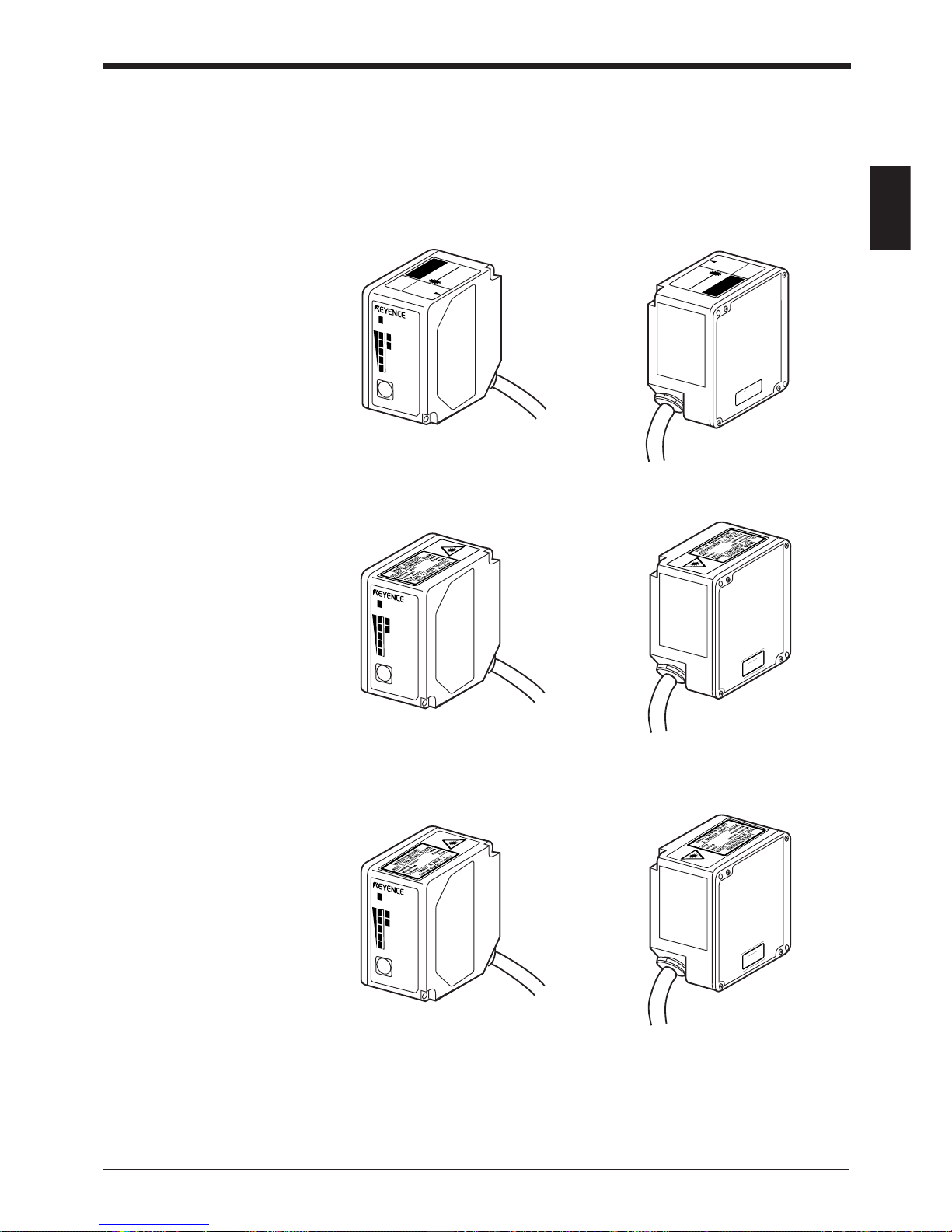
FDA Warning labels are attached to the sensor head as shown below.
The IEC/DIN Warning labels are packaged with the BL-700 Series. Affix the Warning labels on the sensor head as shown below.
■ FDA
■ IEC
■ DIN
LASER RADIATION-
DO NOT STARE INTO BEAM
SEMICONDUCTOR LASER 650nm
MAXIMUM OUTPUT 1.4mW
PULSED RADIATION 91 µm
CLASS II LASER PRODUCT
CAUTION
AVOID EXPOSURE
LASER RADIATION
IS EM
ITTED FROM
THIS APERTURE.
LASER ON
STB
OK/NG
TIMING
TEST
BL-700
CAUTION LASER RADIATION
WHEN OPEN.
DO NOT
STARE INTO BEAM.
LASER RADIATION-
DO NOT STARE INTO BEAM
SE
M
IC
O
N
D
U
C
T
O
R
LA
S
ER
6
50
nm
M
A
XIM
U
M
O
U
TP
U
T
1.4m
W
P
U
LS
E
D
R
AD
IA
T
IO
N
91
µm
C
LA
SS
II LA
S
E
R
P
R
O
D
U
C
T
CAUTIONCAUTION
AVOID EXPOSURE
LASER RADIATION
IS EMITTED FROM
THIS APERTURE.
LASER ON
STB
OK/NG
TIMING
TEST
BL-700
CAUTION
Laser radiation when
open. Do not stare
into beam.
LASER ON
STB
OK/NG
TIMING
TEST
BL-700
VORSICHT
Laserstrahlung wenn
Abdeckung geöffnet.
Nicht in den strahl blicken.
Page 18
Chapter 1 Laser Safety Precautions
1
4
1.4 Safety Consideration
Use of controls or adjustment or the performance of procedures other than those
specified herein may result in hazardous radiation exposure.
The laser beam is not harmful to the skin. There is, therefore, no danger in exposing arms or hands to the beam. The only possible health hazard is in exposing the
eyes to the laser beam. Damage to the eyes can occur if the operator stares
directly into the beam.
Follow the safety precautions below to ensure operator safety:
• Operate the BL-700 Series only according to the procedures described in
this instruction manual.
Otherwise, injury may occur due to exposure to the laser beam.
• Do not disassemble the sensor head.
Laser emission from the BL-700 Series is not automatically stopped if the
sensor head is disassembled. If you disassemble the sensor head for inspection
or repair, you may be exposed to the laser beam. If the BL-700 Series malfunctions, contact KEYENCE immediately.
• Do not look directly at the laser beam.
Looking directly at the laser beam may result in serious eye injury.
• Protective enclosure
We recommend that you install a protective enclosure around the sensor head
to prevent any person from getting near the sensor head during operation.
• Protective goggles
We recommend that you wear protective goggles when using the BL-700
Series.
• Stop laser emissions before cleaning the laser emission port.
Failure to stop the laser emission may expose eyes or skin to the laser beam.
• Check the laser beam path.
To prevent exposure to the laser beam due to specular or diffuse reflection,
install a screen which offers the appropriate reflectance and temperature
characteristics to interrupt the reflected laser beam. Do not install the BL-700
Series in such a way that the laser beam passes at eye height.
1.5 Safety Features Provided with the BL-700 Series
The BL-700 Series is provided with the following safety features. Make sure these
features function correctly before operating.
• Laser emission caution LED (LASER ON LED)
During laser emission, the LASER ON LED illuminates. The LED ON status can be
checked through the laser protective glasses.
• Laser forced OFF command
Sending the laser forced OFF command (LOCK, see P.92) to the BL-700 can
inhibit emission of laser beams. When working near the laser transmitter, be sure
to use the laser forced OFF command to avoid looking into the laser beams.
When this command is selected, the bottom STABILITY LED flashes.
CAUTION
Page 19

Chapter 2
Connection and Installation
2.1 BL-700 connections .............................................................. 6
2.1.1 Connector pin assignment .......................................................6
2.1.2 Power supply connections .......................................................6
2.1.3 Wiring I/O ................................................................................. 7
2.1.4 RS-232C connection................................................................ 7
2.2 Connecting BL-U1 and wiring ............................................. 8
2.2.1 Connecting the power supply .................................................. 8
2.2.2 Connecting the BL-700 ............................................................8
2.2.3 Setting BL-U1 DIP switches..................................................... 9
2.2.4 Terminals of I/O terminal block and wiring............................. 10
2.2.5 Connecting RS-232C ............................................................. 11
2.2.6 Wiring the RS-422A ...............................................................14
2.3 Wiring the KEYENCE power supply unit BL-U2/N-42 ...... 16
2.3.1 Connecting the power supply ................................................ 16
2.3.2 Connecting the BL-700 to BL-U2/N-42 ..................................16
2.3.3 Terminals of I/O terminal block and connections ................... 17
2.3.4 Terminal ................................................................................. 18
2.3.5 Connecting RS-232C (BL-U2) ............................................... 18
2.3.6 Connecting the N-42 to RS-422A .......................................... 21
2.4 Installation ...........................................................................23
2.4.1 Operating environment precautions....................................... 23
2.4.2 Installing the BL-700 Series ................................................... 25
2.4.3 Installing the BL-U1 ............................................................... 27
2.4.4 Installing the BL-U2, N-42...................................................... 27
Page 20
Chapter 2 Connection and Installation
2
6
2.1 BL-700 Connections
This section describes connections when a KEYENCE power supply unit is not
used.
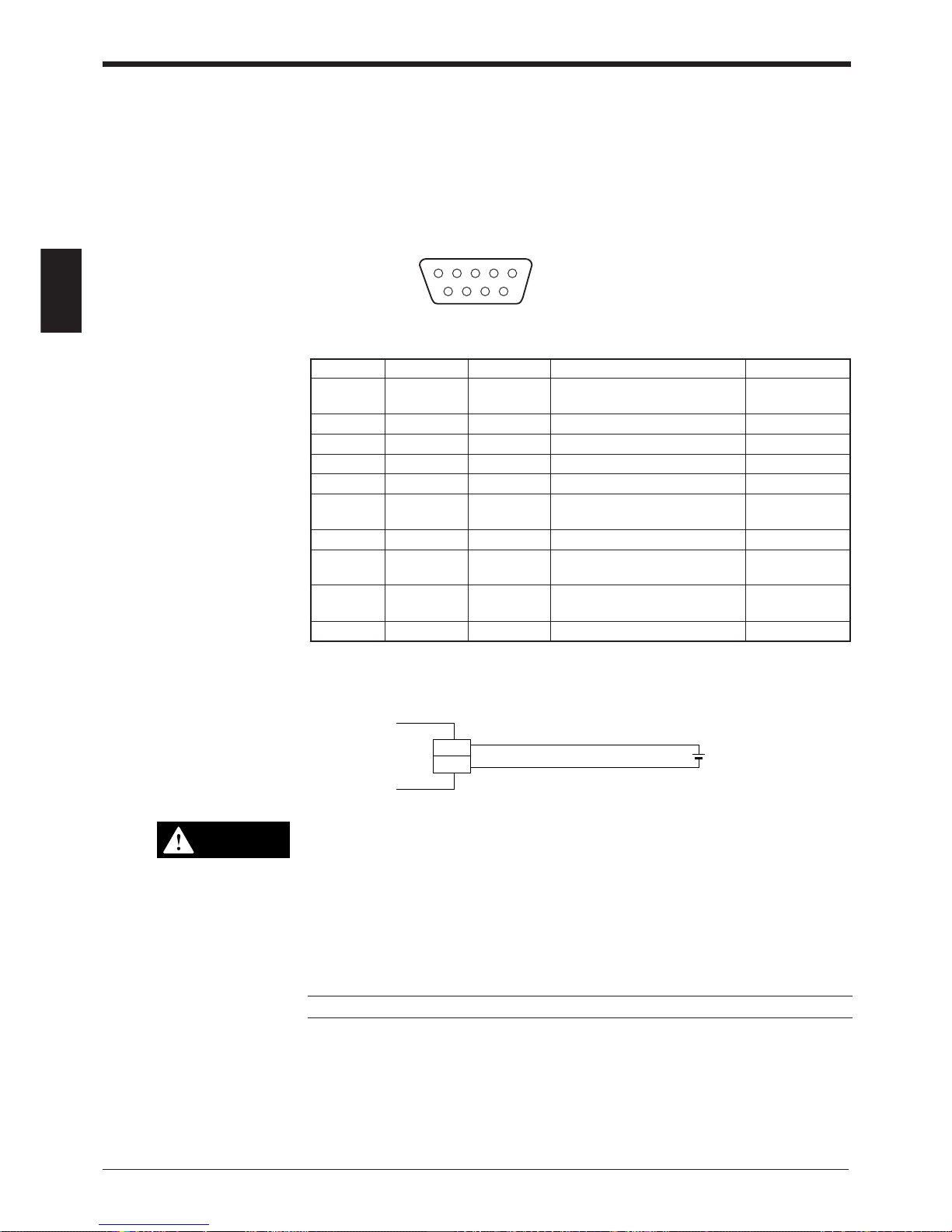
2.1.1 Connector pin assignment
The BL-700 connector has the following pin assignment.
D-sub 9-pin (female)
DTE specification (defined as terminal)
#4-40 screw (male)
12 3 45
6789
2.1.2 Power supply connections
• Be sure to match the polarities of the power supply when soldering the
connections. Reversing the polarities will damage the unit.
• Make sure that the power supply provides a stable 5 VDC ± 5%. If the
power supply does not function in the above range, it can damage the unit.
• Do not extend the power cable. A long power cable can cause a voltage
drop, preventing the BL-700 from starting properly.
Note: If the power supply is UL rated, it must provide Class 2 output.
Pin No. Cable color Symbol Description Signal direction
Connector Shield FG Frame ground —
case
1 Yellow TIM Trigger input Input
2 Brown RD (RXD) Receives RS-232C data Input
3 Purple SD (TXD) Sends RS-232C data Output
4 White OK OK output Output
5 Black GND (SG) Ground (common ground for —
respective signals)
6 Gray NG NG output Output
7 Pink RS (RTS) Request to send RS-232C data Output
(always ON)
8 Blue CS (CTS) Enable to send data through Input
RS-232C
9 Red +5 V +5 V DC power supply Input
5 VDC
BL-700
+5V
9
GND
5
+
CAUTION
Page 21
Chapter 2 Connection and Installation
2
7
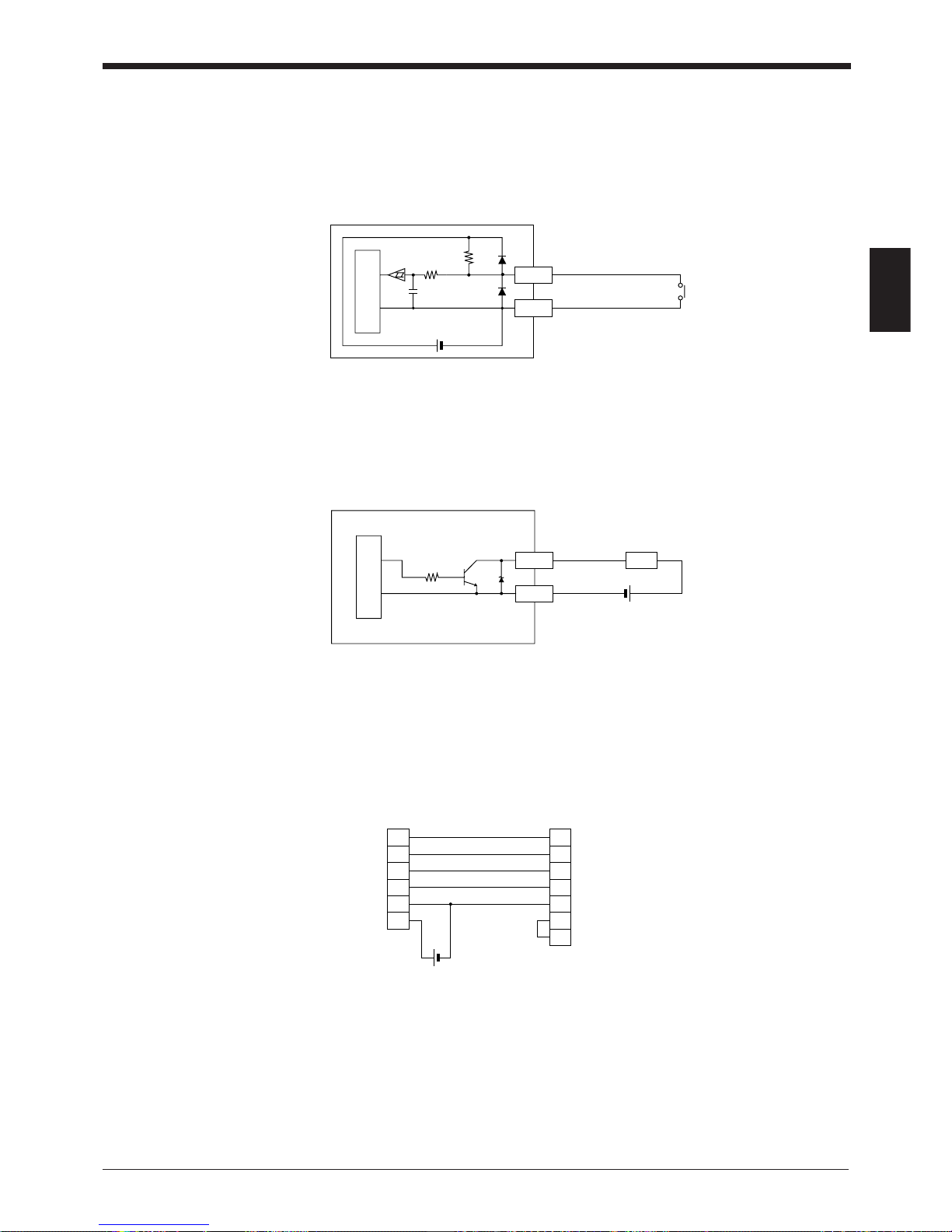
2.1.3 Wiring I/O
■ Trigger input
The trigger input is used to signal the BL-700 to start reading (start laser emission).
The trigger input is a non-voltage input (TTL input is also available with negative
logic).
■ OK/NG output
This output signals whether the readout data is the same as the preset data. When
no preset data has been entered, the signal indicates bar code read status. It is an
NPN open-collector output.
➮
See P. 44
2.1.4 RS-232C connection
Wire the RS-232C as indicated below when connecting the BL-700 to a PC.
■ Connecting the computer with 25-pin
GND
TIM
1
5
5 VDC
10 kΩ
4.7
kΩ
Internal circuit
BL-700
Contact or
solid-state
3
2
8
7
5
9
BL-700
SD
CS
RS
GND
+5V
PC
2
3
4
7
6
5
20
SDRD
RD
RS
CS
SG
DR
ER
D-sub 25-pin (male)
M2.6 screw
D-sub 9-pin (male)
# 4-40 screw
GND
OK/NG
4/6
5
Load
BL-700
10 kΩ
* Rated load: 24 VDC
(30 mA) max.
+
Internal circuit
Page 22

Chapter 2 Connection and Installation
2
8
2.2 Connecting BL-U1 and Wiring
Note: This product does not comply with EC directives.
To use the BL-U1 AC power supply, connect it as described below.
2.2.1 Connecting the power supply
Plug the BL-U1 power cable into an outlet.
Use a power supply with 100 to 240 VAC ± 10% (50/60 Hz).
2.2.2 Connecting the BL-700
Connect the BL-700 to the READER port of the BL-U1.
The BL-U1 READER port pin assignment is as described below.
■ BL-U1 READER port pin assignment
FG line
CAUTION
Pin No. Symbol Function Signal direction
1 TIM Trigger input Output
2 RD (RXD) Receives RS-232C data. Output
3 SD (TXD) Sends RS-232C data. Input
4OKOK Input
5 GND (SG) Ground (Common ground for respective —
signal)
6NGNG Input
7 RS (RTS) Ready to send RS-232C data. Input
8 CS (CTS) Request to send RS-232C data. Output
(Control method can be selected with the DIP
switches.)
➮
See p. 9.
9 +5 V +5 V power supply Output
D-sub 9-pin (male)
DCE specification (defined as terminal)
#4-40 screw (female)
12 3 45
6789
Note: Do not extend a power cable. A long power cable can cause a voltage drop,
preventing the BL-700 from starting properly.
Note: This product does not comply with EC directives.
Page 23
Chapter 2 Connection and Installation
2
9
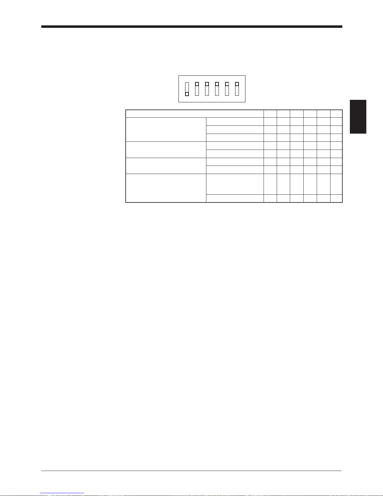
2.2.3 Setting BL-U1 DIP switches
Change the DIP switch settings depending on the selected interface and trigger
input method.
DIP Switch No. 1 2 3 4 5 6
Interface selection RS-232C ON OFF OFF
RS-422A OFF ON OFF
RS-485 multidrop OFF OFF ON
RS-422A terminator OFF OFF
(Termination resistance: 100 ) ON ON
RS-485 terminator OFF OFF
(Termination resistance: 100 ) ON ON
Selection of READER port ON or OFF according
CS control method to the RS-232C port OFF
CS signal status.
Normally ON ON
OFF
ON
123456
* The figure on the left shows the
default settings.
Page 24
Chapter 2 Connection and Installation
2
10
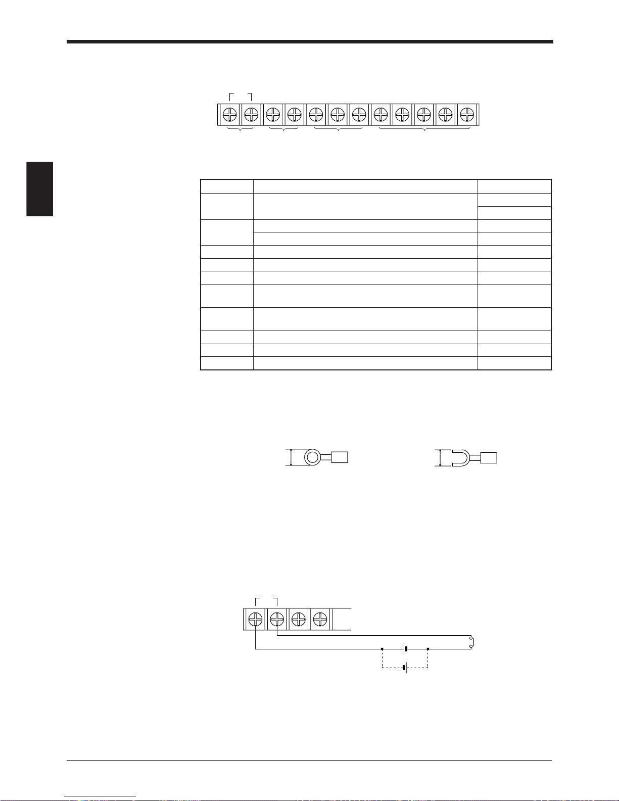
2.2.4 Terminals of I/O terminal block and wiring
* Viewed from the left of the terminal block
• M3.0 screws are used for the terminal block.
• Use the following crimp terminals for connections.
■ Connecting trigger input
The trigger input allows the BL-700 series to start reading bar codes (turn on the
laser beam).
The trigger input is turned ON when 8.5 to 30 VDC input is activated between the
trigger input terminals.
The BL-U1 power supply for the sensor can be used as the input power supply.
Symbol Description Signal direction
TIM Trigger input Input
Input
+12 V OUT- + terminal of power supply for sensor (12 VDC, 300 mA) Output
– terminal of power supply for sensor (0 V) Output
COM Common terminal for OK/NG output —
OK OK output Output
NG NG output Output
SDA + terminal for RS-422A data transmission/ Output,
RS-485 + terminal Input/Output
SDB – terminal for RS-422A data transmission/ Output,
RS-485 - terminal Input/Output
SG Signal ground —
RDA + terminal for RS-422A data reception Input
RDB – terminal for RS-422A data reception Input
TIM +12V OUT– COM OK NG SDA SDB SG RDA RDB
Trigger
input
Power supply
for sensors
(12 VDC, 300 mA)
OK/NG output RS-422A/RS-485
6.0 mm or
less
Round-shape
6.0 mm or
less
Fork-shape
TIM +12V OUT–
8.5 to 30 VDC
+
+
Contact or
solid-state
Page 25
Chapter 2 Connection and Installation
2
11
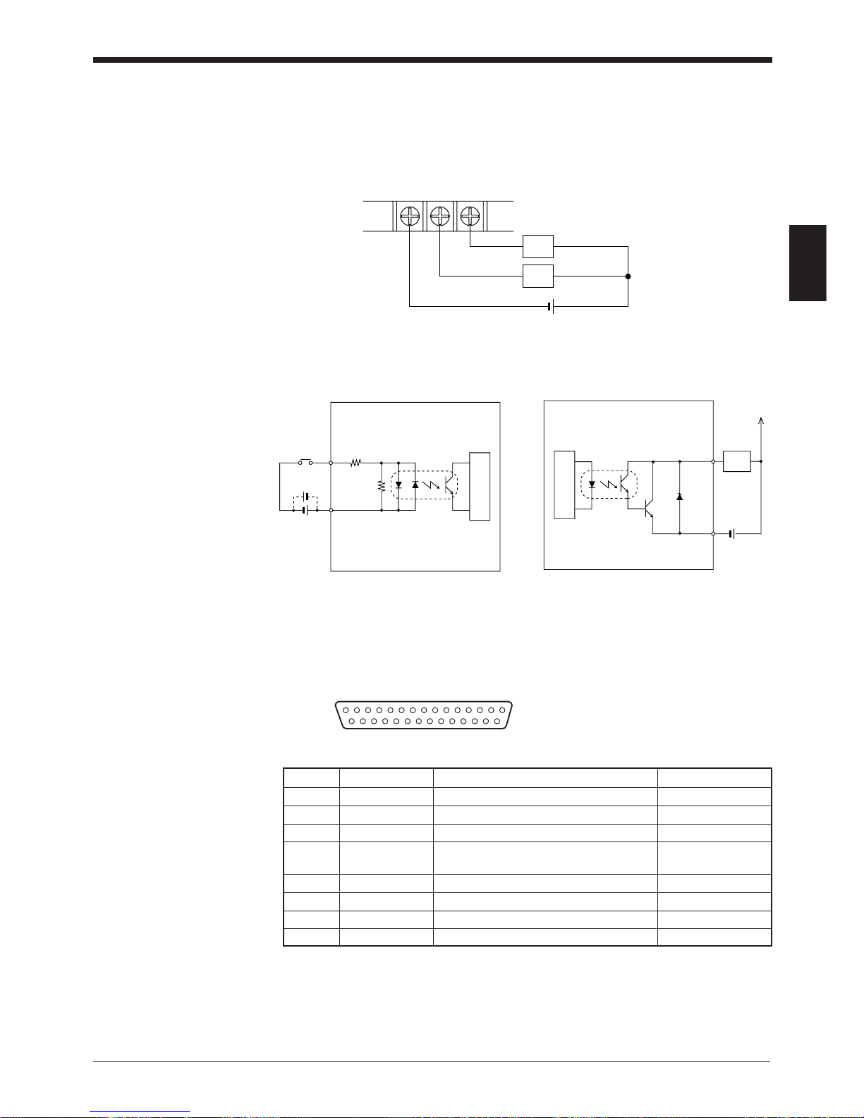
■ Connecting OK/NG output
The OK/NG output is used to differentiate between acceptable and unacceptable
results based on the comparison with the preset data, and to indicate whether or
not the BL-700 series successfully read bar codes.
➮
See P.44.
The OK/NG output is an open-collector output.
■ I/O circuit diagram
• Input circuit diagram • Output circuit diagram
2.2.5 Connecting RS-232C
Pin assignment
COM OK NG
Load
Load
+
*Rated load: 30 V max. (100 mA)
TIM
2.4
kΩ
3.3 kΩ
Internal circuit
Load
OK/NG
COM
+
Internal circuit
13 1
25 14
D-sub 25-pin (female)
DCE specification (defined as terminal)
M2.6 screw (female)
Pin No. Symbol Function Signal direction
1FG Frame ground —
2 SD (TXD) Sends RS-232C data Output
3 RD (RXD) Receives RS-232C data Input
4 RS (RTS) Ready to send RS-232C data Output
(always ON)
5 CS (CTS) Request to send RS-232C data Input
6 DR (DSR) Connected to pin No. 20 inside. Input
7 GND (SG) Signal ground —
20 ER (DTR) Connected to pin No. 6 inside. Output
Page 26
Chapter 2 Connection and Installation
2
12
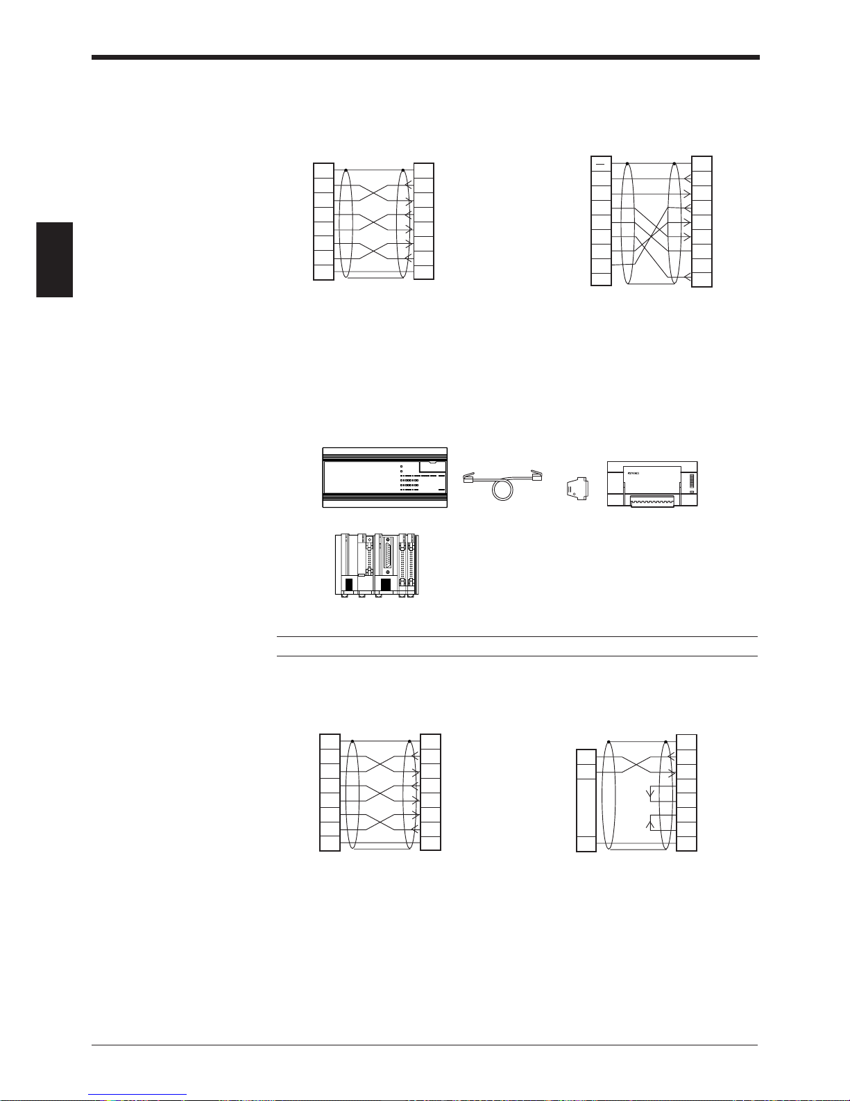
Wiring the RS-232C cable
■ Connecting a PC
25-pin serial port 9-pin serial port
■ Connecting KV series/Handheld programmer port
Use the optional cable manufactured by KEYENCE.
■ Connecting KV-L2*
Port 1 Port 2
2
PC
SD
RD
RS
CS
DR
ER
SG
3
4
5
6
2
11
BL-U1
SD
FGFG
RD
RS
CS
DR
ER
SG
3
4
5
6
20
7
20
7
D-sub 25-pin (male)
M2.6 screw
D-sub 25-pin (male)
M2.6 screw
* KEYENCE option OP-22149 (1.5 m)
or commercially available cross cable
can be used.
* KEYENCE option OP-22149 (1.5 m)
and OP-25057 (conversion connector) can be used.
2
PC
SD
CD
RD
RS
CS
DR
SG
ER
3
4
5
6
2
1
BL-U1
SD
FG
RD
SG
RS
CS
DR
ER
3
4
5
6
7
8
7
8
201
D-sub 25-pin (male)
M2.6 screw
Connector case
D-sub 9-pin (female)
#4-40 screw
OP-96369
BL-U1*
OP-96368 (2.5 m)
KV-10, 16, 24
KV-40, 80
KV-300*
2
KV-L2
SD
RD
RS
CS
DR
ER
SG
3
4
5
6
2
11
BL-U1*
SD
FGFG
RD
RS
CS
DR
ER
SG
3
4
5
6
20
7
20
7
D-sub 25-pin (male)
M2.6 screw
D-sub 25-pin (male)
M2.6 screw
3
KZ-L2
SD
RD
SG
5
2
1
BL-U1*
SD
FG
RD
RS
CS
DR
ER
SG
3
4
5
6
20
71
D-sub 25-pin (male)
M2.6 screw
Terminal block
* KEYENCE option OP-22149 (1.5 m) or
commercially available cross cable can be
used.
Note: KV-300 and BL-U1 are not available in Europe.
Page 27
Chapter 2 Connection and Installation
2
13
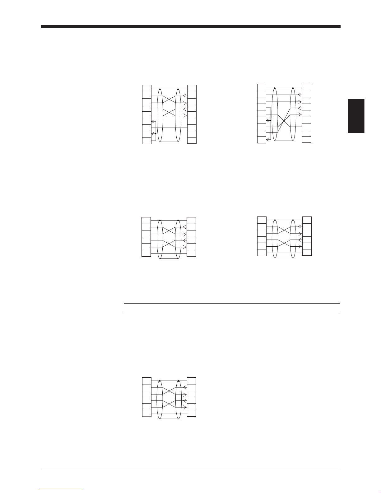
■ Connecting MELSEC-A series
Connection with AJ71C24,
AL71C24-S■■,
A0J2-C214-S1,
AJ71UC24
■ SYSMAC-C series
Connection with C-200H-LK201(-V1),
C-500-LK203,
C-500-LK201-V1,
C120-LK201-V1
Note: KV-L2 and BL-U1 are not available in Europe.
Connection with C-200HS(CPU21/23/31/33),
CQM1(CPU21/41/42/43/44),
C-200HE(CPU42),
C200HG(CPU43/63),
C200HX(CPU44/64),
C200HW-COM02/COM04/COM05/COM06
2
Link unit
SD
RD
RS
CS
DR
SG
ER
3
4
5
6
2
11
BL-U1*
SD
FGFG
RD
RS
CS
DR
SG
ER
3
4
5
6
7
20
7
20
CD
88
D-sub 25-pin (male)
M2.6 screw
D-sub 25-pin (male)
M2.6 screw
2
Link unit
RD
SD
ER
SG
DR
RS
CD
3
4
5
6
2
1–
BL-U1*
SD
FGConnector case
RD
RS
CS
DR
SG
ER
3
4
5
6
7
20
7
1
CS
88
D-sub 25-pin (male)
M2.6 screw
D-sub 9-pin (male)
M2.6 screw
Connection with A1SJ71(U)C24-R2/PRF,
A2CCPUC24,
A2CCPUC24-PRF
Connection with C-20H,
C-28H,
C-40H,
C-60H
* KEYENCE option OP-22149 (1.5 m) or
commercially available cross cable can be
used.
2
Link unit
SD
RD
RS
CS
SG
3
4
5
7
2
11
BL-U1*
SD
FGFG
RD
RS
CS
SG
3
4
5
7
D-sub 25-pin (male)
M2.6 screw
D-sub 25-pin (male)
M2.6 screw
2
PLC
SD
RD
RS
CS
SG
3
4
5
7
2
11
BL-U1*
SD
FGFG
RD
RS
CS
SG
3
4
5
7
D-sub 25-pin (male)
M2.6 screw
D-sub 9-pin (male)
M2.6 screw
2
PLC
SD
RD
RS
CS
SG
3
4
5
9
2
11
BL-U1*
SD
FGFG
RD
RS
CS
SG
3
4
5
7
D-sub 25-pin (male)
M2.6 screw
D-sub 9-pin (male)
M2.6 screw
Page 28
Chapter 2 Connection and Installation
2
14
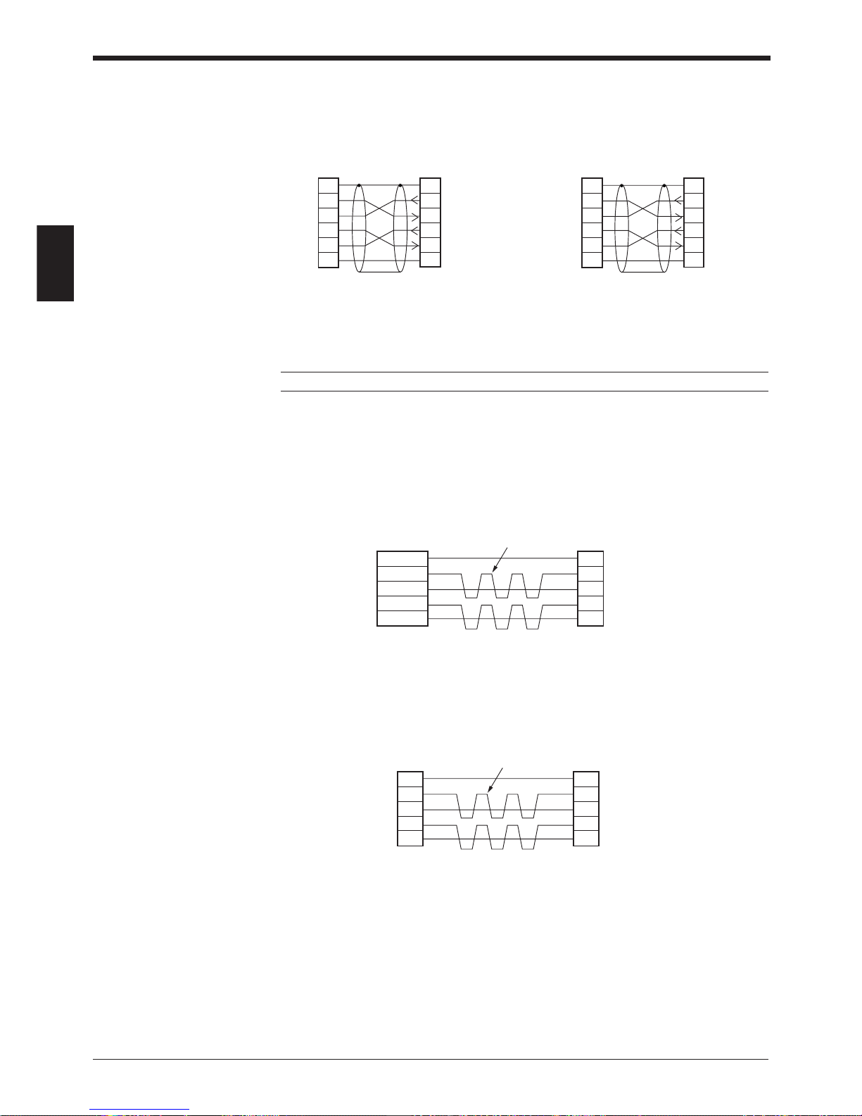
■ SYSMAC-CV series
Connection with CV500-LK201
(Port 1)
Note: BL-U1 is not available in Europe.
2.2.6 Wiring the RS-422A
Wire the RS-422A as indicated below.
■ Connecting a general RS-422A unit
Use the same wiring when connecting the BL-U1 to the BL-U1*.
• Turn ON the terminators (BL-U1/external unit terminal resistance: 100 ).
➮
See P.35
.
• The cable can be extended to within 1.2 km.
■ Connecting KV-L2*
Connecting the unit to RS-422A port 2
SDA
SG
BL-U1*
SDB
RDA
RDB
RD + (RDA)
SG
External unit
BL-U1*
RD – (RDB)
SD + (SDA)
SD – (SDB)
Twisted pair cable
SDA
SG
BL-U1*
SDB
RDA
RDB
RDB
SG
Link Unit
RDA
SDB
SDA
Twisted pair cable
Connection with CV500-LK201 (Port 2),
CV500,
CV1000,
CVM1
* KEYENCE option OP-22149 (1.5 m) or
commercially available cross cable can be
used.
2
Link unit
SD
RD
RS
CS
SG
3
4
5
7
2
11
BL-U1*
SD
FGFG
RD
RS
CS
SG
3
4
5
7
D-sub 25-pin (male)
M2.6 screw
D-sub 25-pin (male)
M2.6 screw
2
PLC
SD
RD
RS
CS
SG
3
4
5
9
2
11
BL-U1*
SD
FGFG
RD
RS
CS
SG
3
4
5
7
D-sub 25-pin (male)
M2.6 screw
D-sub 9-pin (male)
M2.6 screw
Page 29
Chapter 2 Connection and Installation
2
15
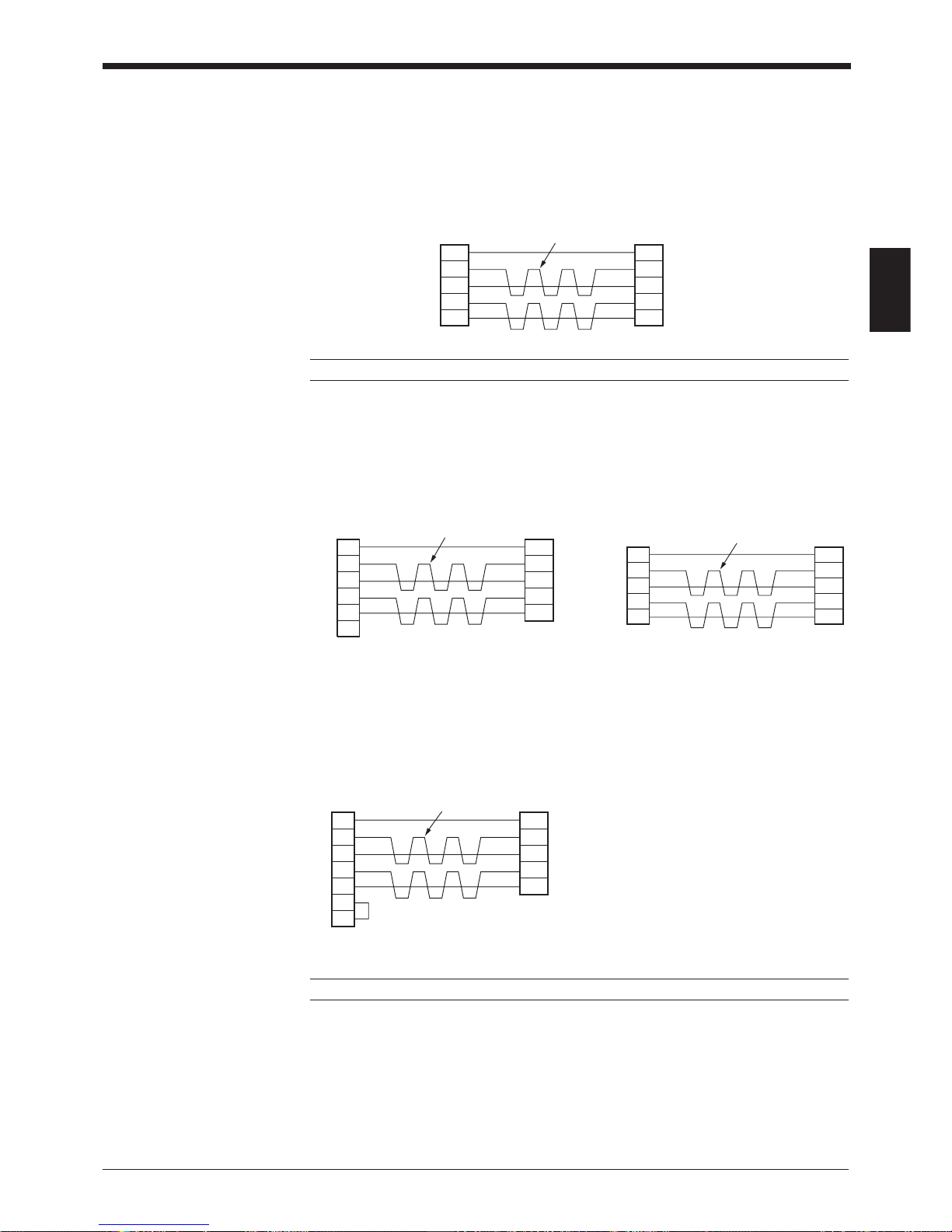
■ Connecting the MELSEC-A series
Connecting with AJ71C24,
AJ71C24-S■■,
AJ71UC24,
A0J2-C214-S1,
A1SJ71(U)C24-R4
Note: BL-U1 and KV-L2 are not available in Europe.
■ Connecting SYSMAC-C series
Connecting with C200H-LK202 (-V1), Connecting with C200HW-COM03/
C500-LK201-V1, COM06
C500-LK203,
C120-LK202-V1
■ Connecting SYSMAC-CV series
Connecting with CV-500-LK201,
CV500,
CV1000,
CVM1
Note: BL-U1 is not available in Europe.
SDA
SG
BL-U1*
SDB
RDA
RDB
RDA
SG
Link unit
RDB
SDA
SDB
Twisted pair cable
SDA
SG
BL-U1*
SDB
RDA
RDB
Link unit
1RDB
RDA
SDB
SDA
FG
6
5
9
7
3
SG
D-sub 9-pin (male)
M2.6 screw
Twisted pair cable
SDA
SG
BL-U1*
SDB
RDA
RDB
8RDB
RDA
SDB
SDA
6
2
1
9
SG
D-sub 9-pin (male)
M2.6 screw
Twisted pair cable
Communication
board
SDA
SG
BL-U1*
SDB
RDA
RDB
PLC
8RDB
RDA
SDB
SDA
RS
CS
6
2
1
4
9
SG
5
D-sub 9-pin (male)
M2.6 screw
Twisted pair cable
Page 30
Chapter 2 Connection and Installation
2
16
24 VDC
+
+–
24V DC IN
24 VDC
+
+–
24V DC IN
N.C. N.C. N.C.
CAUTION
D-sub 9-pin (male)
DCE specification (defined as terminal)
#4-40 screw (female)
12 3 45
6789
POWER SD RD
READER
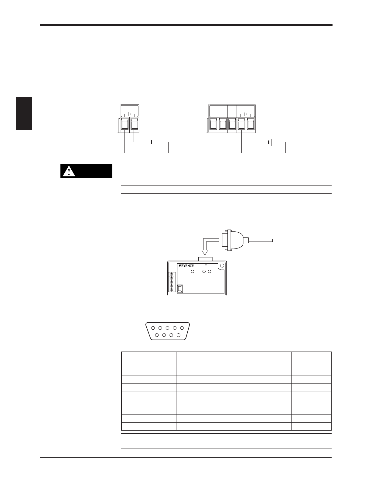
2.3 Wiring the KEYENCE Power Supply Unit BL-U2/N-42
To use the BL-U2/N-42, connect as indicated below.
2.3.1 Connecting the power supply
Connect BL-U2/N-42 to a 24 VDC power supply.
BL-U2 N-42
Make sure that the power supply provides 24 VDC. If the power supply output
is not 24 VDC, it can damage the unit.
Note: If the power supply is UL rated, it must provide Class 2 output.
2.3.2 Connecting the BL-700 to BL-U2/N-42
Connect the BL-700 to the READER port of the BL-U2/N-42.
■ READER port pin assignment
Note: Do not extend a power cable. A long power cable can cause a voltage drop,
preventing the BL-700 from starting properly.
Pin No. Symbol Function Signal direction
1 TIM Trigger input Output
2 RD (RXD) Receives RS-232C data Output
3 SD (TXD) Sends RS-232C data Input
4OK OK signal Input
5 GND (SG) Ground (Common ground for respective signal) —
6NG NG signal Input
7 RS (RTS) Ready to send RS-232C data Input
8 CS (CTS) Request to send RS-232C data Output
9 +5 V 5 V power supply output Output
Page 31
Chapter 2 Connection and Installation
2
17
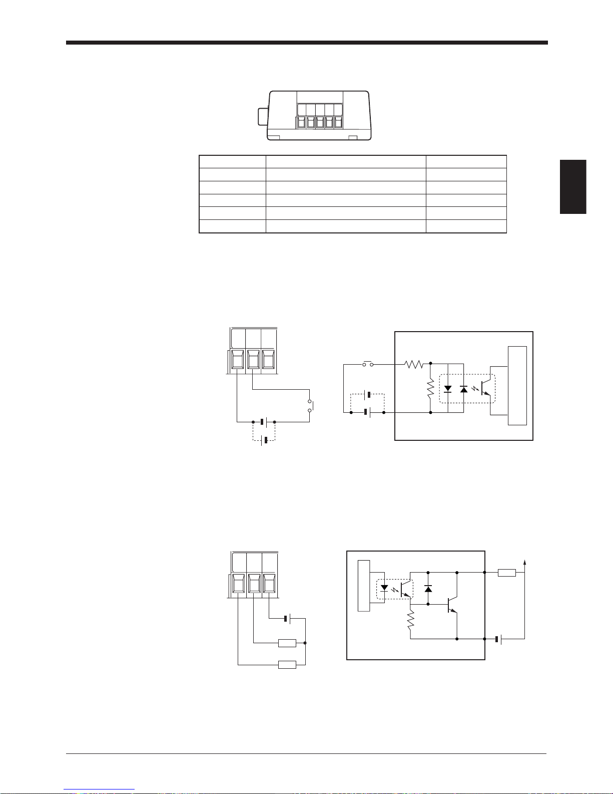
2.3.3 Terminals of I/O terminal block and connections
■ Connecting trigger input
The trigger input allows the BL-700 to start reading bar codes (turn on the laser
beam).
To turn ON the trigger input, supply 15 to 26 VDC between the trigger input terminals.
■ Connecting OK/NG output
The OK/NG output indicates the result of the comparison with preset data, or
indicates whether reading is successful or not.
+
OK
NG COM
Load
Load
Internal circuit
+
Load
* Viewed from the left of the unit
Symbol Description Signal direction
TIM Trigger input Input
COM Common terminal for trigger input Input
OK OK output Output
NG NG output Output
COM Common terminal for output Output
TIM
COM
OK OG
COM
15 to 26 VDC
+
+
TIM
COM
OK
TIM
COM
Internal circuit
+
+
* Rated load: 30 V max. (100 mA)
Page 32
Chapter 2 Connection and Installation
2
18
5 mm max.
6 mm min
2.0 mm
max.
12 3 45
6789
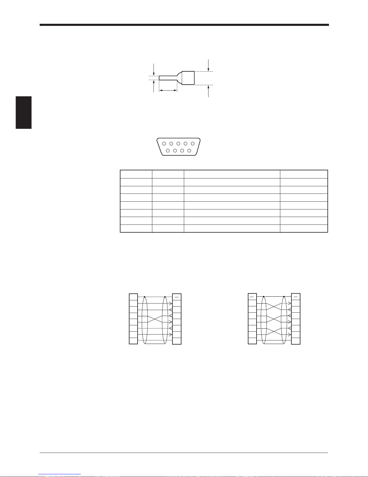
Pin No. Symbol Description Signal direction
2 RD (RXD) Receive data Input
3 SD (TXD) Send data Output
4 ER (DTR) Connected to pin No.6 inside. Output
5SG Signal ground —
6 DR (DSR) Connected to pin No.4 inside. Input
7 RS (RTS) Request to send data (always ON) Output
8 CS (CTS) Enable to send data Input
2.3.4 Terminal
A solderless contact pin, as shown below, is available for connection.
2.3.5 Connecting RS-232C (BL-U2)
Pin assignment
* One connector is provided.
Wiring the RS-232C cable
■ Connecting a PC
25-pin serial port 9-pin serial port
D-sub 9-pin (male)
DTE specification (defined as terminal)
#4-40 screw
2
PC
RD
SD
FG
ER
SG
DR
CS
RS
3
4
5
6
2
1
BL-U2
RD
Connector case
SD
DR
SG
RS
CS
ER
3
7
8
4
6
5
20
7
D-sub 25-pin (male)
M2.6 screw
D-sub 9-pin (female)
#4-40 screw
* KEYENCE option OP-22149 (1.5 m)
or OP-25057 (conversion connector)
can be used.
* KEYENCE option cable OP-27937 (1.5
m) can be used.
2
PC
SD
RD
DR
SG
ER
CS
RS
3
7
8
4
2
BL-U2
RD
Connector case
SD
DR
SG
RS
CS
ER
3
7
8
4
6
5
6
5
D-sub 9-pin (female)
#4-40 screw
D-sub 9-pin (female)
#4-40 screw
Connector case
Page 33
Chapter 2 Connection and Installation
2
19
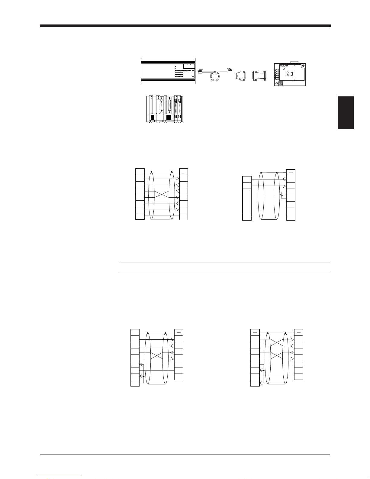
■ Connecting KV series/Handheld programmer port
Use the optional cable manufactured by KEYENCE.
■ Connecting KV-L2*
Port 1 Port 2
Note: KV-300, KV-L2 and BL-U1 are not available in Europe.
■ Connecting MELSEC-A series
Connection with AJ71C24,
AL71C24-S■■,
A0J2-C214S1,
AJ71UC24
OP-96369 OP-25057
BL-U2
OP-96368 (2.5 m)
KV-10, 16, 24
KV-40, 80
KV-300*
POWER
SD
RD
BL-U2
RS-232C
READER
2
Link unit
SD
RD
RS
CS
DR
SG
ER
3
4
5
6
2
1
BL-U2
RD
FG
SD
RS
CS
ER
SG
DR
3
7
8
4
57
20
CD
68
D-sub 25-pin (male)
M2.6 screw
Connector case
D-sub 9-pin (female)
#4-40 screw
2
Link unit
RD
SD
RS
CS
ER
DR
CD
3
7
8
4
2
BL-U2
RD
SD
RS
CS
ER
DR
SG
3
7
8
4
66
1
SG
55
D-sub 9-pin (male)
M2.6 screw
Connector caseConnector case
D-sub 9-pin (female)
#4-40 screw
Connection with A1SJ71(U)C24-R2/PRF,
A2CCPUC24,
A2CCPUC24-PRF
* KEYENCE option OP-22149 (1.5 m) or the
OP-25057 (conversion connector) can be
used.
2
KV-L2*
RD
SD
FG
ER
SG
DR
CS
RS
3
4
5
6
2
1
BL-U2
RD
Connector case
SD
DR
SG
RS
CS
ER
3
7
8
4
6
5
20
7
D-sub 25-pin (male)
M2.6 screw
D-sub 9-pin (female)
#4-40 screw
3
KV-L2*
SD
RD
SG
5
2
BL-U1*
RD
SD
RS
CS
ER
DR
SG
3
7
8
4
6
51
D-sub 9-pin (female)
#4-40 screw
Terminal block
Connector case
Page 34

Chapter 2 Connection and Installation
2
20
■ SYSMAC-C series
Connection with C-200H-LK201(-V1),
C-500-LK203,
C-500-LK201-V1,
C120-LK201-V1
■ SYSMAC-C series
Connection with C-200HS(CPU21/23/31/33),
CQM1(CPU21/41/42/43/44),
C-200HE(CPU42),
C200HG(CPU43/63),
C200HX(CPU44/64),
C200HW-COM02/COM04/COM05/COM06
■ SYSMAC-CV series
Connection with CV500-LK201 Connection with CV500-LK201
(Port 1) (Port 2),
CV500,
CV1000,
CVM1
Connection with C-20H,
C-28H,
C-40H,
C-60H
* KEYENCE option OP-22149 (1.5 m) or the
OP-25057 (conversion connector) can be
used.
2
Link unit
SD
RD
RS
CS
SG
3
4
5
7
2
1
BL-U2
RD
FG
SD
RS
CS
SG
3
7
8
5
D-sub 25-pin (male)
M2.6 screw
Connector case
D-sub 9-pin (female)
#4-40 screw
2
PLC
SD
RD
RS
CS
SG
3
4
5
7
2
1
BL-U2
RD
FG
SD
RS
CS
SG
3
7
8
5
D-sub 9-pin (male)
M2.6 screw
Connector case
D-sub 9-pin (female)
#4-40 screw
2
PLC
SD
RD
RS
CS
SG
3
4
5
9
2
1
BL-U2
RD
FG
SD
RS
CS
SG
3
7
8
5
D-sub 9-pin (male)
M2.6 screw
Connector case
D-sub 9-pin (female)
#4-40 screw
* KEYENCE option OP-22149 (1.5 m) or the
OP-25057 (conversion connector) can be
used.
2
Link unit
SD
RD
RS
CS
SG
3
4
5
7
2
1
BL-U2
RD
FG
SD
RS
CS
SG
3
7
8
5
D-sub 25-pin (male)
M2.6 screw
Connector case
D-sub 9-pin (female)
#4-40 screw
2
PLC
SD
RD
RS
CS
SG
3
4
5
9
2
1
BL-U2
RD
FG
SD
RS
CS
SG
3
7
8
5
D-sub 9-pin (male)
M2.6 screw
Connector case
D-sub 9-pin (female)
#4-40 screw
Page 35
Chapter 2 Connection and Installation
2
21
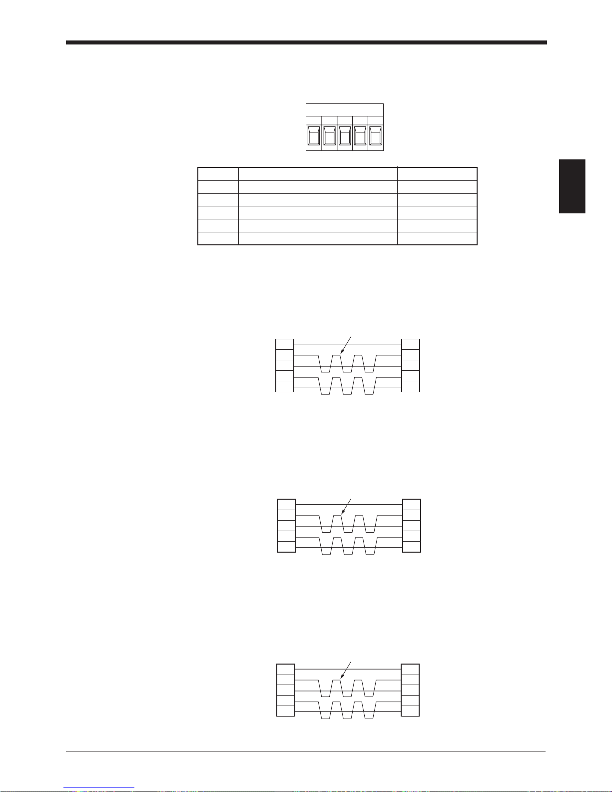
2.3.6 Connecting the N-42 to RS-422A
RS-422 terminal block assignment
Connecting external equipment
■ Connecting N-42 to external unit
Use the same wiring when connecting the N-42 to the N-42.
• Turn ON the terminators (BL-U1/external unit terminal resistance: 100 ).
➮
See P. viii.
• The cable can be extended to within 1.2 km.
■ Connecting KV-L2*
Connecting the unit to RS-422A port 2
■ Connecting the MELSEC-A series
Connecting with AJ71C24,
AJ71C24-S■■,
AJ71UC24,
A0J2-C214-S1,
A1SJ71(U)C24-R4
RS-422
SG SD+ RD+SD– RD–
SD +
SG
N-42
External unit
(N-42)
SD –
RD +
RD –
RD +
SG
RD –
SD +
SD –
Twisted pair cable
Code Description Signal direction
SG Ground —
SD+ Sends data to + terminal. Output
SD- Sends data to - terminal. Output
RD+ Receives data from + terminal. Input
RD- Receives data from - terminal. Input
SD+
SG
BL-U1*
SD–
RD+
RD–
RDB
SG
Link unit
RDA
SDB
SDA
Twisted pair cable
SD+
SG
BL-U1*
SD–
RD+
RD–
RDA
SG
Link unit Twisted pair cable
RDB
SDA
SDB
Page 36
Chapter 2 Connection and Installation
2
22
SD+
SG
N-48
SD–
RD+
RD–
Link unit Twisted pair cable
1RDB
RDA
SDB
SDA
FG
6
5
9
7
3
SG
D-sub 9-pin (male)
M2.6 screw
SD+
SG
N-48Twisted pair cable
Communication
board
SD–
RD+
RD–
8RDB
RDA
SDB
SDA
6
2
1
9
SG
D-sub 9-pin (male)
M2.6 screw
SD+
SG
N-42
SD–
RD+
RD–
PLC Twisted pair cable
8RDB
RDA
SDB
SDA
RS
CS
6
2
1
4
9
SG
5
D-sub 9-pin (male)
M2.6 screw
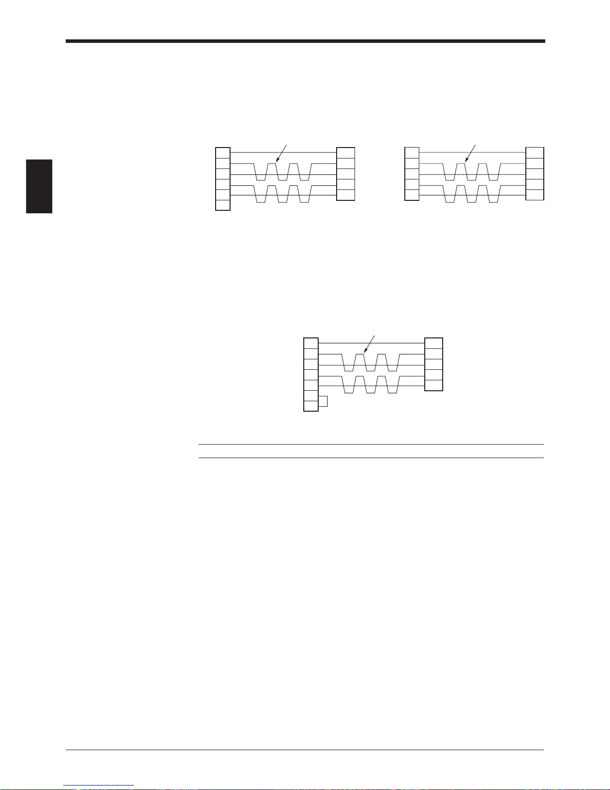
■ Connecting SYSMAC-C series
Connecting with C200H-LK202 (-V1), Connecting with C200HW-COM03/
C500-LK201-V1, COM06
C500-LK203,
C120-LK202-V1
■ Connecting SYSMAC-CV series
Connecting with CV-500-LK201,
CV500,
CV1000,
CVM1
Note: BL-U1 and KV-L2 are not available in Europe.
Page 37

Chapter 2 Connection and Installation
2
23
2.4 Installation
2.4.1 Operating environment precautions
Ambient environments
This unit is a precision instrument and you must take care in choosing the operating environment. Do not install the unit in place as shown below:
• The unit is exposed to direct sunlight, or the ambient temperature may fall
below 0°C (32°F) or exceed 40°C (104°F) (Power supply: 0 to 50°C (32 to
122°F));
• The relative humidity may exceed the range of 35 to 85%, or condensation may
occur due to rapid temperature changes;
• Corrosive gas or inflammable gas is present, or a high level of dust, salt, iron
particles or soot is present;
• The unit is subject to vibration or impact;
• Water, oil or chemicals may splash the unit;
•A strong magnetic field or electric field is generated.
• The ambient illumination intensity exceeds the range defined in the specification
in P.120.
In-panel installation
To mount the power supply unit BL-U1, BL-U2 or N-42, carefully observe the
following instructions.
• Provide enough ventilation space.
• If the ambient temperature may fall below 0°C (32°F) or exceed 50°C (122°F),
provide a fan or air conditioner.
• Do not mount this unit in a panel where a high voltage device is installed.
• Place this unit as far away from power lines as possible.
Note: The BL-700 conforms to the protective structure defined in IP-65 (excluding
the power supply unit connected). Although installation environments subject to
dust and water will not affect the BL-700, adhesion of dust or water drops to the
transmitter/receiver may disable readout of bar codes.
Hints on correct use
• Trigger (TIM) input
Set the trigger input to be long enough to allow the laser beam to cover the entire
bar code.
If the trigger input needs to be on for only a short period of time, select one-shot
mode.
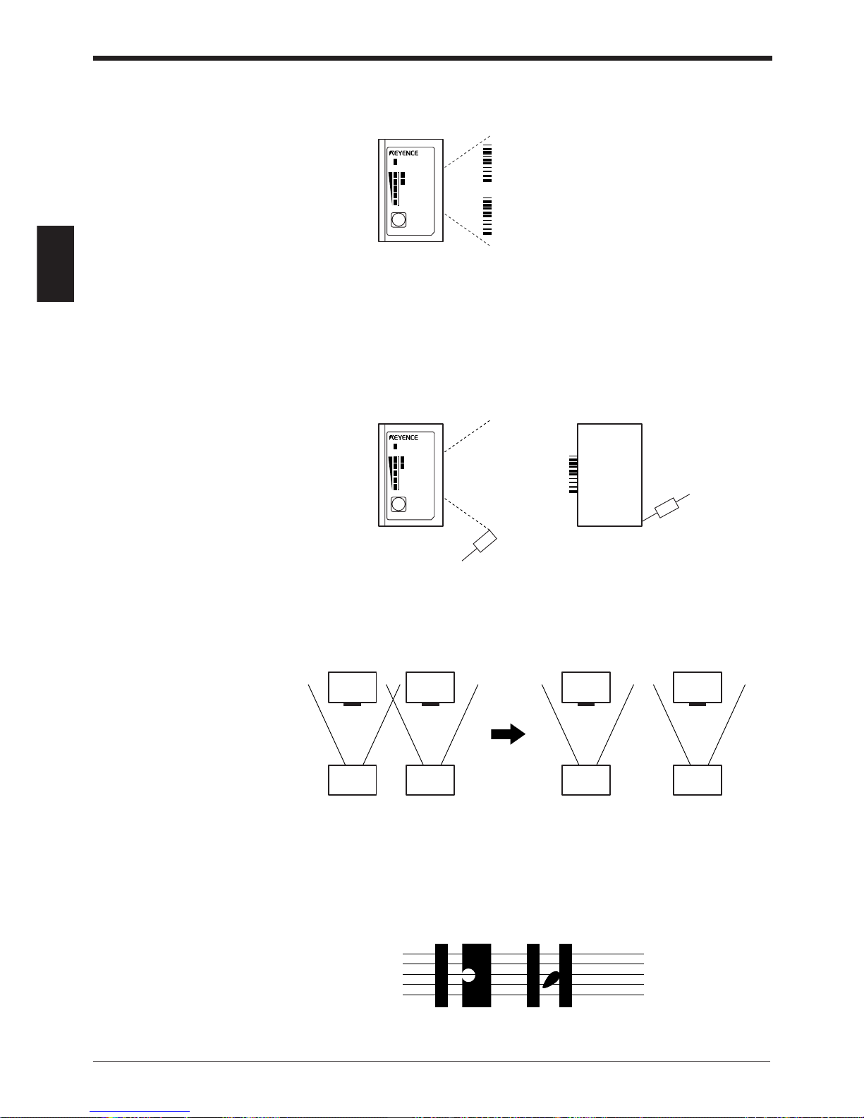
• Influence from mirror surface
If a mirror surface (metallic surface) is near the bar code and the laser beam
reflects off the mirror, the BL-700 may cause a read error. Protect the unit from the
influence of a mirror surface by covering the surface or changing the bar code label
position.
Page 38
Chapter 2 Connection and Installation
2
24
LASER ON
STB
OK/NG
TIMING
TEST
BL-700
LASER ON
STB
OK/NG
TIMING
TEST
BL-700
Optical pickup
Light source
Object
Bar code
• Bar code pitch
Do not place several bar codes in the field of the laser beam, unless you are in
multi-label read mode (Multi 3).
If you use multi-label read mode (multi 3), the BL-700 can simultaneously read 2 to
4 bar codes in the field of the laser beam.
• Influence from photoelectric sensor
When using a photoelectric sensor to control trigger, block the sensor beam so it
does not enter the BL-700 optical pickup.
The beam from the photoelectric sensor can interfere with the BL-700, deteriorating
reading performance. If this case, reposition the photoelectric sensor.
• Interference between the BL-700 units
When two BL-700 units are placed adjacent to each other with only a small separation, the mutual laser beams result in interference and will cause a readout error.
To avoid interference, place the units as far apart as possible.
• When a bar code is stained or partially missing
Use a raster scan reader (BL-701/741/781) when a bar code is stained or partially
missing. This raster scan readers scan several portions of the bar code. Normal
portions of the bar code, even with stained or missing portions, can be read by the
BL-700.
Page 39
Chapter 2 Connection and Installation
2
25
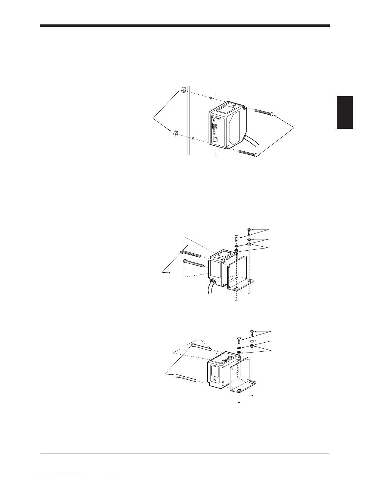
2.4.2 Installing the BL-700 series
Installation method
Use the mounting holes on the side panel to install the unit.
■ Installation with no mounting bracket
• Select screws of the proper length by checking the thickness of the plate used
for mounting. (The screws provided are for use with the mounting bracket.)
• For the mounting hole diameter, see P.127.
■ Using the supplied mounting brackets
Vertical scanning
Horizontal scanning
• Use the set screw to secure the mounting bracket to the unit.
• For the mounting hole diameter, see P.127.
• When the insulating spacer is mounted, it can reduce the influence of noise
from the mounting bracket.
LASER ON
STB
OK/NG
TIMING
TEST
BL-700
M3 screws
M3 nuts
M3 screws
(accessory)
M4 screws
Washer (accessory)
Insulating spacer
(accessory)
M3 screws
(accessory)
LASER ON
STB
OK/NG
TIMING
TEST
BL-700
Insulating spacer
(accessory)
M4 screws
Washer (accessory)
Page 40
Chapter 2 Connection and Installation
2
26
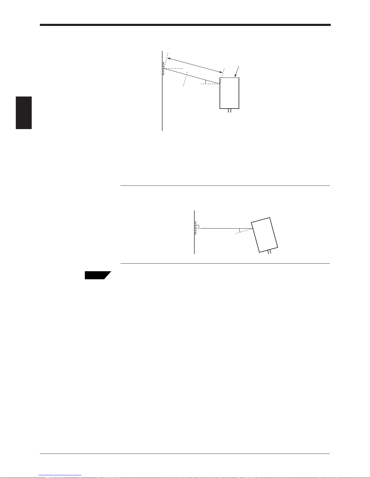
Mounting angle and mounting distance
Set the angle and reading distance by referring to the read range characteristics
and angle characteristics described on P.122 to P.124.
The allowable reading distance and angle may vary depending on the narrow bar
width of the bar code, the bar code size, and the readability of the bar code. Set
these parameters after performing a test read of the required bar code using the
unit.
Note: Do not set the unit at an angle at which the laser beam is perpendicular to
the surface of the bar code. The beam will be fully reflected into the reader, making
correct reading impossible (
➮
See P.124
).
The reading check test mode allows you to set the optimal reading position.
➮
To use the test mode, see P. 38.
10°
Tips
Panel surface
* Reading distance = 230 mm (BL-700/701)
380 mm (BL-740/741)
500 mm (BL-780/781)
10°
Reading distance
Incorrect
Page 41
Chapter 2 Connection and Installation
2
27
AB
4 - ø5
150
98
POWER
SD
RD
BL-U2
RS-232C
READER
63.2 mm
43.2 mm
2 - ø4.5 mm
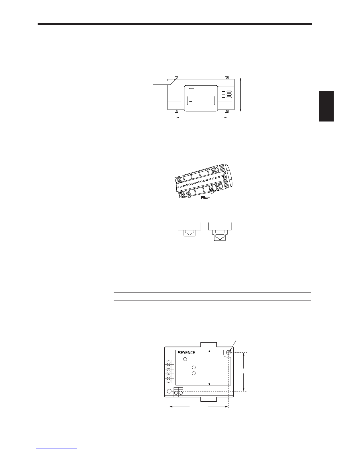
2.4.3 Installing the BL-U1*
There are 2 methods for installing the BL-U1:
■ When installing the BL-U1 directly
Pull out the 4 screw slots on the rear panel and screw them to the base.
■ When installing the BL-U1 to the DIN rail
1. Hook the BL-U1 to the DIN rail groove from its top. Push the BL-U1 bottom
against the DIN rail until you hear a click.
2. Check that the DIN rail mounting notch is shaped like notch A below. If not,
push the BL-U1 further.
3. To remove the BL-U1 from the DIN rail, pull out the notch until its shape turns
from Fig. B to Fig. A. Then, disengage the BL-U1 from the DIN rail.
4. When you want to reinstall the BL-U1 to the DIN rail, return the notch from that
of Fig. A to Fig. B.
Note: BL-U1 is not available in Europe.
2.4.4 Installing the BL-U2, N-42
Install the BL-U2 or N-42 using the mounting hole.
* The BL-U2 is 21 mm thick and the N-42 is 26 mm thick.
Page 42

Chapter 2 Connection and Installation
2
28
Page 43

Chapter 3
Functions for Reading Operation
3.1 Read Operation ................................................................... 30
3.1.1 Scanning method ................................................................... 30
3.1.2 Data-send mode .................................................................... 32
3.2 Read Modes ......................................................................... 33
3.2.1 Single label read mode ..........................................................33
3.2.2 Multi-label read mode 1 (Multi 1) ........................................... 33
3.2.3 Multi-label read mode 2 (Multi 2) ........................................... 34
3.2.4 Multi-label read mode 3 (Multi 3) ........................................... 35
3.3 Label Orientation Mode ...................................................... 37
3.4 Test Mode ............................................................................ 38
3.4.1 Reading rate check mode ...................................................... 38
3.4.2 Tact check mode ................................................................... 39
3.4.3 Online test mode.................................................................... 41
3.5 STABILITY LEDs ................................................................. 42
3.6 Preset Function (Compare with:) ...................................... 44
3.6.1 What is the preset function? .................................................. 44
3.6.2 Wildcard Symbols (“!” and “?”) .............................................. 45
3.7 Additional Information .......................................................46
3.8 Max. Code Length (Designated Digit )
Output Function .................................................................. 48
Page 44
Chapter 3 Functions for Reading Operation
30
3
3.1 Read Operation
3.1.1 Scanning method
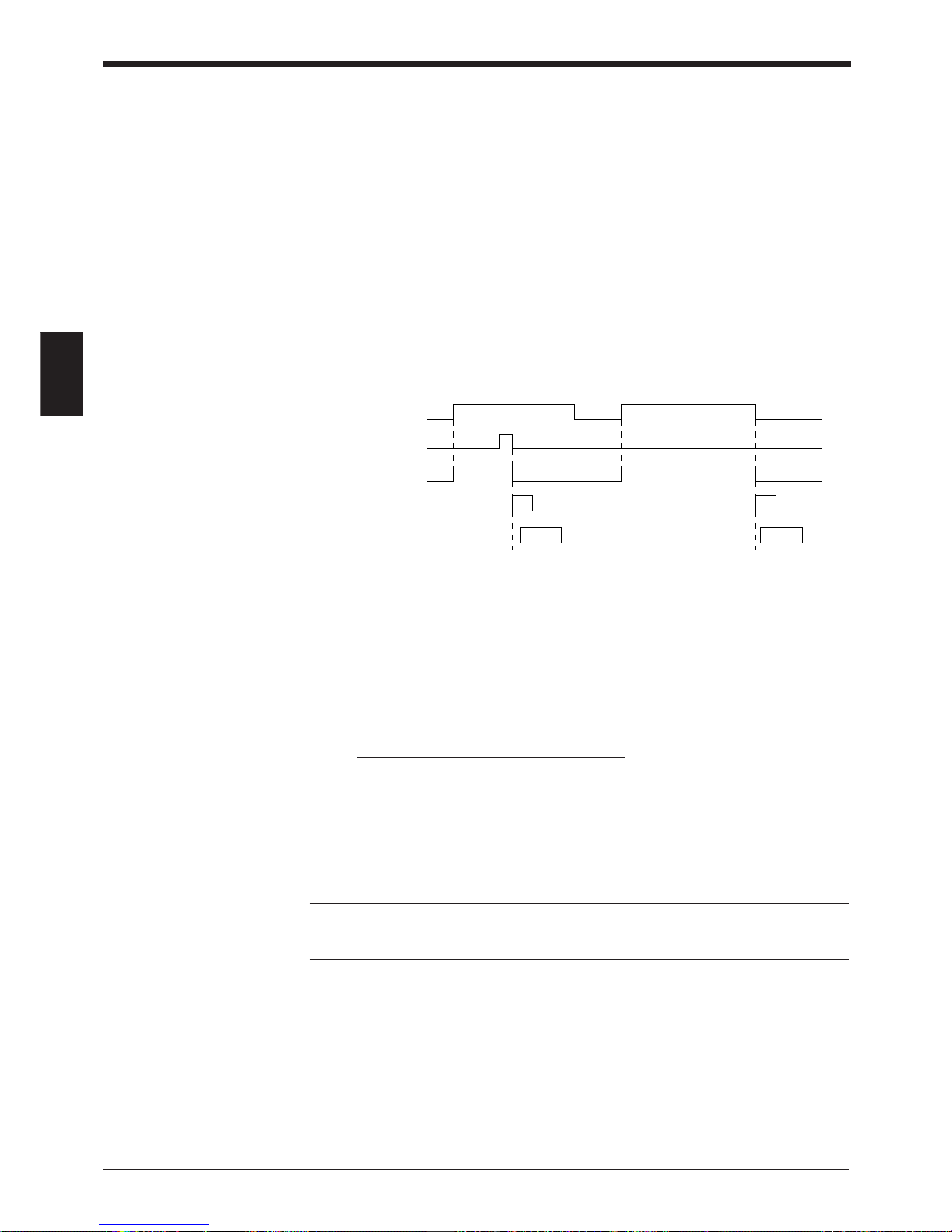
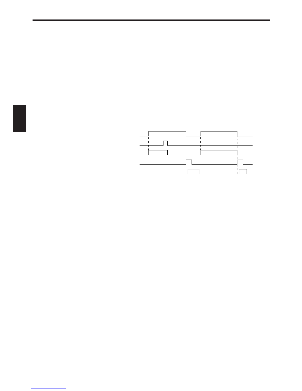
There are two methods for triggering the BL-700 to read bar codes; the “Level
signal” method and the “One-shot signal” method. The example given for these two
methods uses the “single label read mode” (
➮
see P.33
), which reads one bar code
while trigger input turns on once, and uses the “after read” as the data-send mode
(
➮
see P.32
).
■ Level signal trigger
When the trigger input turns on, laser emission begins and the unit begins reading.
The laser turns off after reaching the specified decode count. Then, the unit sends
the readout data.
*1. Set trigger input so that it stays on long enough for the laser beam to cover the
entire bar code.
*2. After the trigger input exceeds the preset input time, the laser begins to emit.
➮
See note on the next page.
*3. The communication time can be obtained from the following expression:
*4. The length of time that the OK/NG output is on can be changed to between 10
ms and 2.55 s.
*5. The OK/NG output turns on 5 ms after the data has been read (or trigger input
turns off in case of reading failure).
Note: 5 seconds after the power switch turns on or an UNLOCK command (
➮
see
P.90
) is sent, the unit will not start reading a bar code by turning on the trigger
input.
Trigger input
Bar code
Laser beams
Communication time
OK/NG output OK/NG NG
<Succeed to read> <Fail to read>
*2
*1
*3
*4
*5
(Code length of data to be
sent + Header/number of
characters in delimiter)
X
Data bits + (1: If parity is used) + Start/stop bit
Baud rate
Page 45
Chapter 3 Functions for Reading Operation
31
3
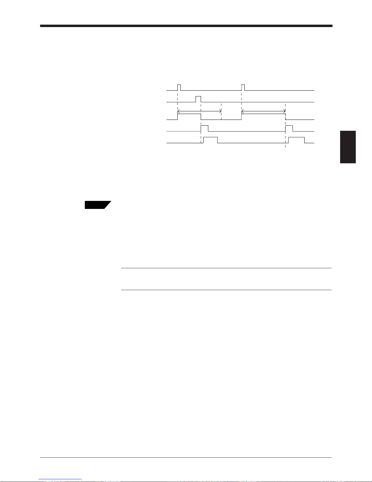
■ One-shot signal trigger
The unit detects the rising edge of the trigger input and starts reading bar codes for
the preset input time. The laser beam turns off after reaching the specified decode
count and the unit sends the readout data.
The remaining actions are the same as those for level signal trigger.
1. After the trigger input exceeds the preset input times, the laser begins to emit.
Trigger input minimum ON time:
4 ms (when the trigger input value is 2 ms)
13 ms (when the trigger input value is 10 ms)
• The BL-700 can read up to 4 types of bar codes without changing the bar code type
setting (➮ see P.61).
• For general operation, see “Level signal trigger”
Choose “One-shot signal trigger” when the trigger input signal is very short or you
want to set the input time.
• To use a one-shot trigger signal instead of trigger input, gently press the TEST switch
once (for less than 3 seconds) (➮ see P.vi).
NOTE: The BL-700 has a built-in AGC (auto gain control) circuit. It requires a
maximum of 3 scans (4.3 ms) to adjust gain. The BL-700 generates a maximum of
4.3 ms delay until starting to read the data after the laser beam turns ON.
OK/NG
NG
<Succeed to read> <Fail to read>
Trigger input
Bar code
*1
Preset input time
Preset input time
Laser beams
Communication time
OK/NG output
Tips
Page 46
Chapter 3 Functions for Reading Operation
32
3
3.1.2 Data-send mode
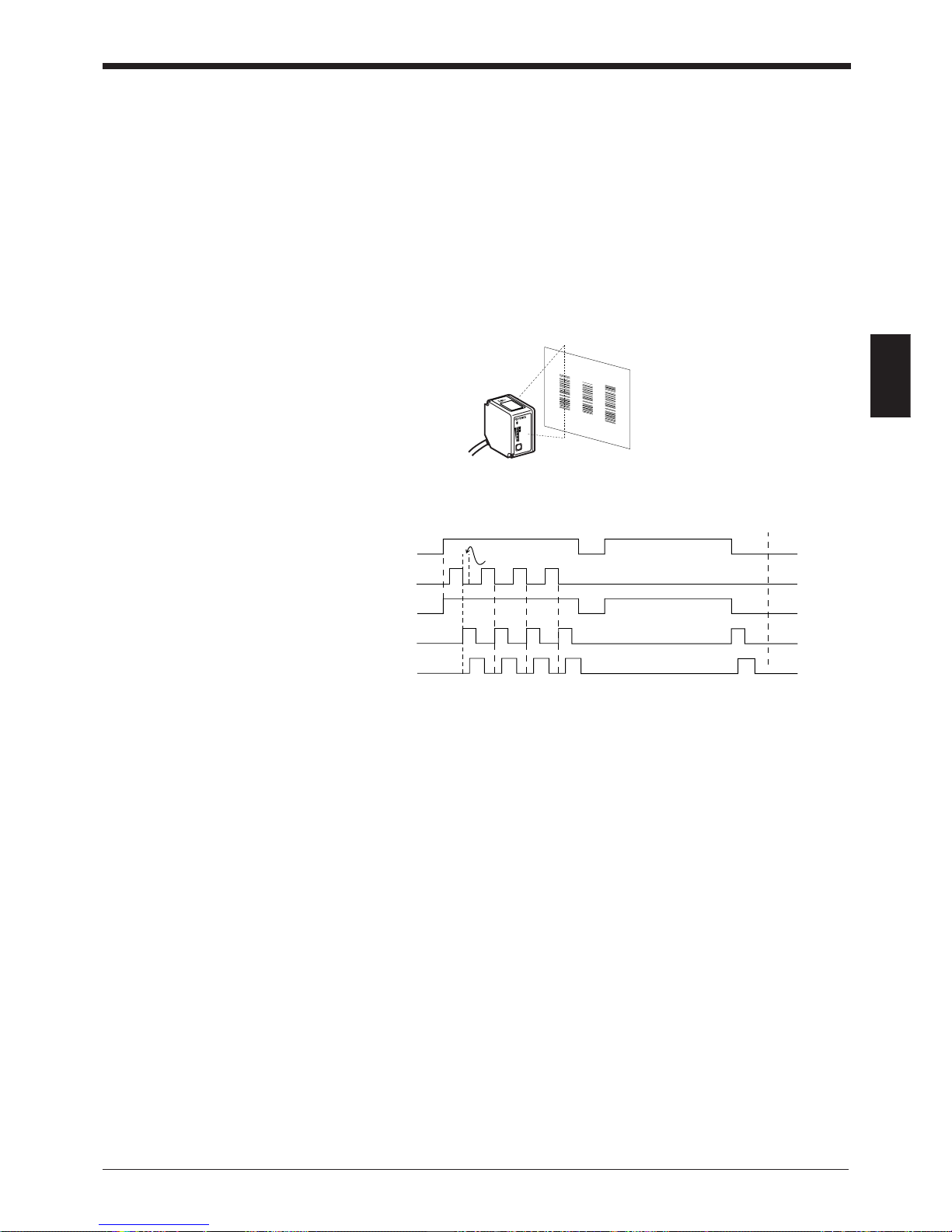
In the single label read mode only, you can select from the two data send modes
(OK/NG output on trigger) described below: In the multi-label read mode, you can
only select the “send after reading” mode.
• Send after read
The unit outputs the communication and OK/NG signals after a successful read
(trigger output turns on as many times as the preset decode count). This is the
same operation as in the time chart described in “3.1.1 Scanning method”. Normally, this is the method you should use.
• Send at trigger input
The unit outputs the communication and OK/NG signal when the trigger input turns
off (or the preset input time has passed if one-shot signal trigger is selected).
OK/NG
NG
<Succeed to read>
<Fail to read>
Trigger input
Bar code
Laser beams
Communication time
OK/NG output
Page 47
Chapter 3 Functions for Reading Operation
33
3
3.2 Read Modes
The BL-700 provides 4 types of read modes.
3.2.1 Single label read mode
This mode allows the unit to read one bar code during one trigger input signal. The
operation and timing chart are described on page 30 to 32.
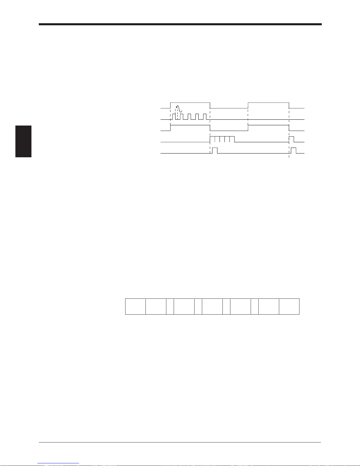
3.2.2 Multi-label read mode 1 (Multi 1)
This mode allows the unit to read several bar codes printed on one label as shown
below during one trigger input signal. The unit outputs the readout data sequentially.
Multi-label read mode 1 operation
• In the multi-label read mode 1, the unit reads several bar codes continuously,
and outputs them sequentially as it reads while laser beam remains on and
trigger input turns on after bar codes have been read (or during the preset input
time if one-shot signal trigger is selected).
• To prevent the unit from reading the same bar code twice, the time for one bar
code to pass across the laser beam’s field and read, plus the repeat reading
time must be set (100 ms to 25.5 s). During the repeat reading time, the unit
cannot read the same bar code repeatedly, but can read different bar codes.
•A reading error is issued only when the unit cannot read any bar code while the
trigger input is on.
• For OK/NG output, “OK” turns on every time the unit reads a bar code and “NG”
turns on if the unit fails to read a bar code. (Comparison to the preset data is not
performed.)
LASER ON
STB
OK/NG
TIMING
TEST
BL-700
Repeat reading time
OK
NG
<Succeed to read> <Fail to read>
Trigger input
Bar code
Laser beams
Communication time
OK/NG out
p
ut
OK OK OK
Page 48
Chapter 3 Functions for Reading Operation
34
3
3.2.3 Multi-label read mode 2 (Multi 2)
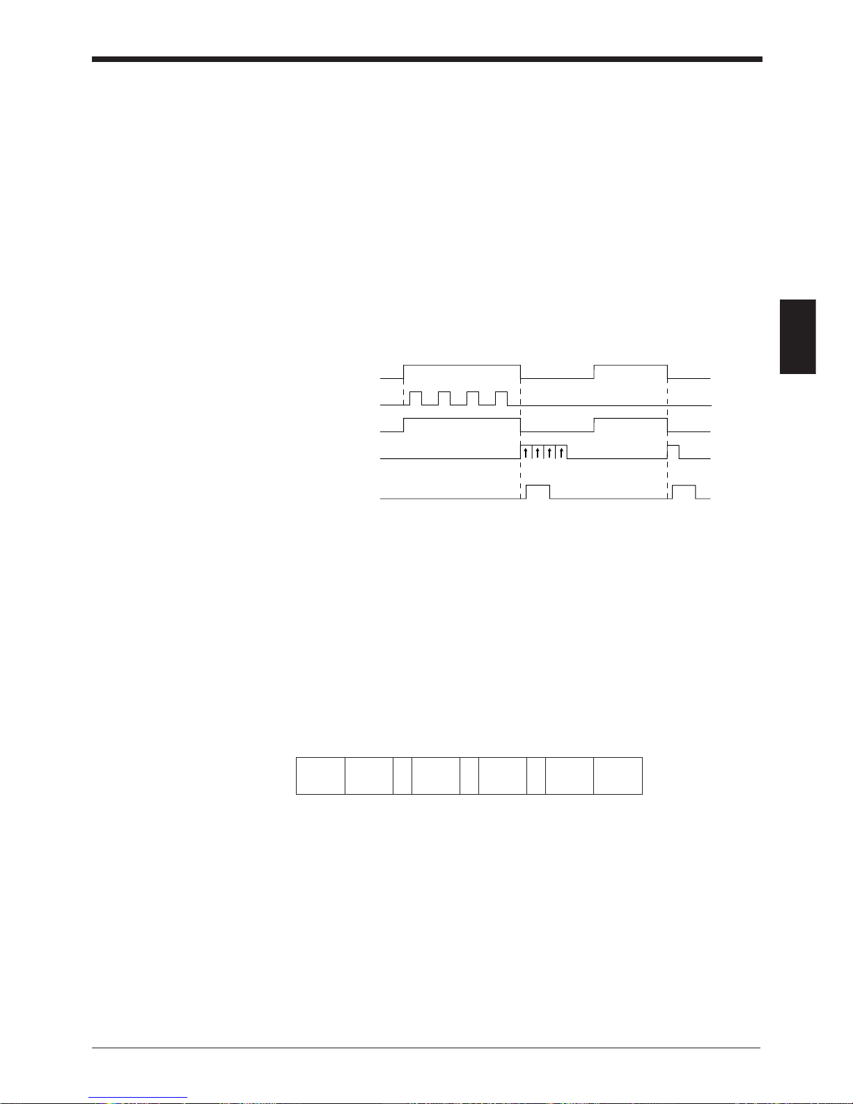
As with multi 1 mode, this mode allows the unit to read several bar codes continuously while the trigger input is on. (The number of bar codes that can be read
depends on the buffer capacity. See P.86.) The difference between the two modes
is that multi 2 mode sends all the readout data at one time after the trigger input
turns off.
Multi-label read mode 2 operation
• Multi 2 mode allows the unit to read several bar codes while the trigger input is
on (or during the preset input time if one-shot signal trigger is selected) and
sends all the readout data at one time after the trigger input turns off (or after
the preset input time is expired if one-shot signal trigger is selected).
• To prevent the unit from reading the same bar code twice, the time for one bar
code to pass across the laser beam’s field and read, plus the repeat reading
time must be set (100 ms to 25.5 s). During the repeat reading time, the unit
cannot read the same bar code repeatedly, but can read different bar codes.
•A reading error is issued only when the unit cannot read any bar code while the
trigger input is on.
• For OK/NG output, after trigger input turns off, “OK” turns on if the unit reads at
least one bar code and “NG” turns on if the unit fails to read a bar code. (Comparison to the preset data is not performed.)
Reading data format
• Each data packet is separated by a comma (, : 2CH) (intermediate delimiter).
• The unit sends as many data packets the number of bar codes read.
➮
See P.87 for “header string” and “delimeter”.
Repeat reading
time
12345
12345
OK
NG
<Succeed to read> <Fail to read>
Trigger input
Bar code
Laser beams
Communication time
OK/NG output
Header 1st data
, , , ,
2nd data 3rd data 4th data Delimiter•••••••
Page 49
Chapter 3 Functions for Reading Operation
35
3
3.2.4 Multi-label read mode 3 (Multi 3)
As described in multi-label read modes 1 and 2, this mode also allows the unit to
read several bar codes (up to 4 codes) while the trigger input is on.
The unit sends the readout data at one time according to a specified sequence
after the trigger input turns off. When up to 4 codes are in the laser beam’s field,
the unit can simultaneously reads all of them.
Operation of multi-label read mode 3
This mode allows the unit to continuously read each one of 4 bar code types “Code
1”, “Code 2”, “Code 3”, and “Code 4” as specified in the “code setup” of the setup
software (
➮
see P.61
). If 3 types are specified in the “code setup”, the unit reads 3
bar codes (each of 3 types). If 2 types are specified, the unit reads 2 bar codes.
The following time chart is given.
* The above example chart is with all 4 codes specified in the “code setup” of the
setup software.
• The bar code reading sequence is not fixed.
• The unit communicates the readout data in the order of Code 1 to Code 4. After
the trigger input turns off, the unit sends all the data at one time.
• For OK/NG output, “OK” turns on if the unit reads all the specified Codes 1 to 4
and “NG” turns on if the unit fails to read at least one bar code. (Comparison to
the preset data is not performed.)
Reading data format
• Each data packet is separated by a comma (, : 2CH) (intermediate delimiter).
• If an read error occurs on any one of Codes 1 to 4, or the corresponding bar
code does not exist, “ERROR” (➮
see P.87 for the reading error codes
), instead
of the read data is sent.
➮
See P.87 for “header string” and “delimeter”.
OK
Trigger input
Bar Code
Laser beams
Communication time
OK/NG output
Code 1 Code 2 Code 3 Code 4
Code 1
Code 2
Code 3
Code 4
NG
Header
Data read
from Code
1
Data read
from Code
2
Data read
from Code
3
Data read
from Code
4
, , ,Delimiter
Page 50
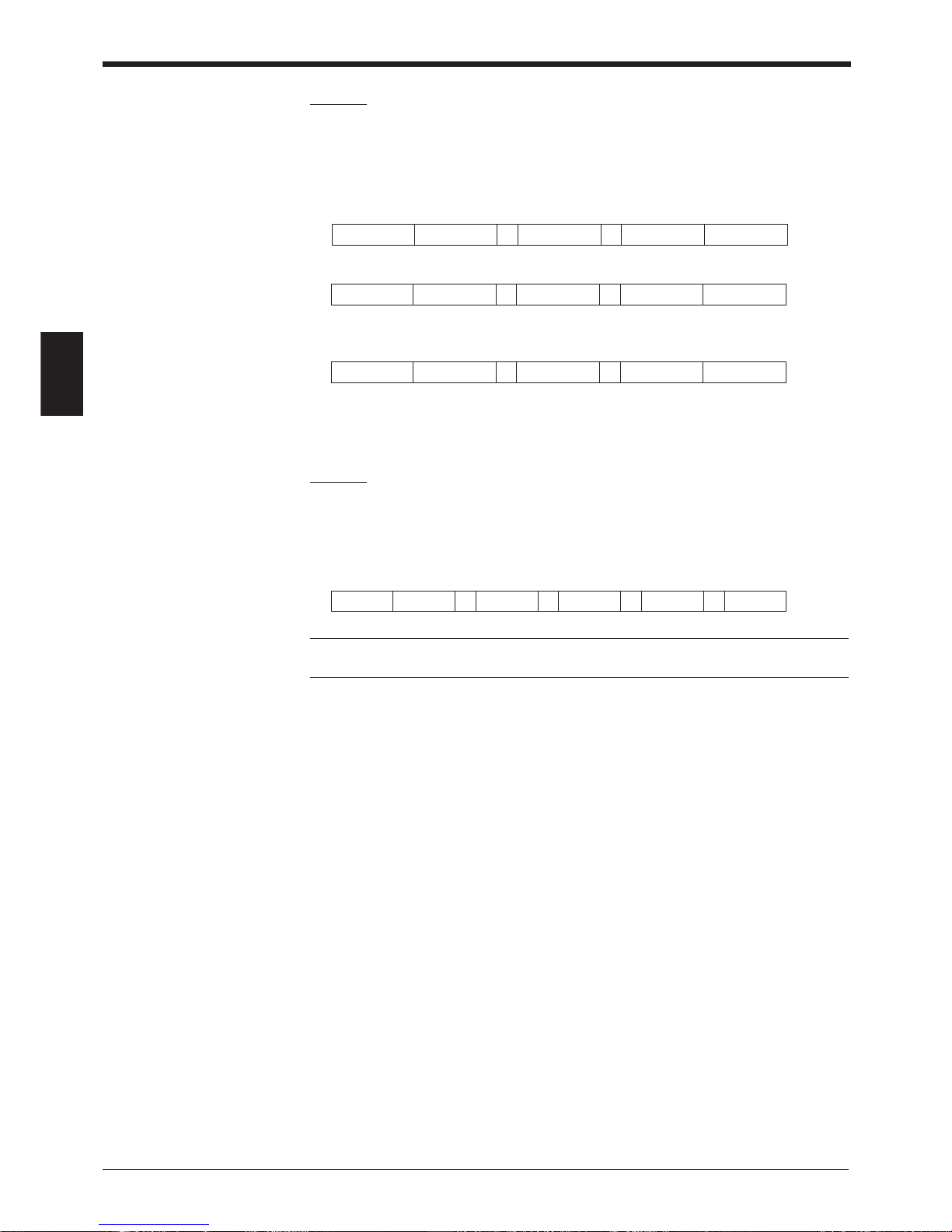
Chapter 3 Functions for Reading Operation
36
3
Example
Suppose that the following codes are specified:
Code 1: CODE39, 10 digits
Code 2: EAN/UPC, 13 digits
Code 3: None
Code 4: CODE39, 8 digits
When the unit successfully reads all 3 types of codes:
When the unit fails to read Code 1 (CODE39, 10 digits)
When the unit fails to read Code 1 (CODE39, 10 digits) and Code 4 (CODE39, 8
digits)
• When the same type of data having the same digits is specified to all Codes 1
to 4, the unit sends the data in the reading order.
Example
Suppose that the following codes are specified:
Code 1: CODE39, 7 digits
Code 2: CODE39, 7 digits
Code 3: CODE39, 7 digits
Code 4: CODE39, 7 digits
Note: The unit cannot read the bar code having the same content twice while
trigger input turns on once.
Header ABCDE12345 KEYENCE1 Delimiter
4901234567894
, ,
Header ERROR KEYENCE1 Delimiter
4901234567894
, ,
Header ERROR ERROR Delimiter
4901234567894
, ,
Header ABCD123 XYZ3333 1234567 Delimiter
, , , ,
KEYENCE
Page 51
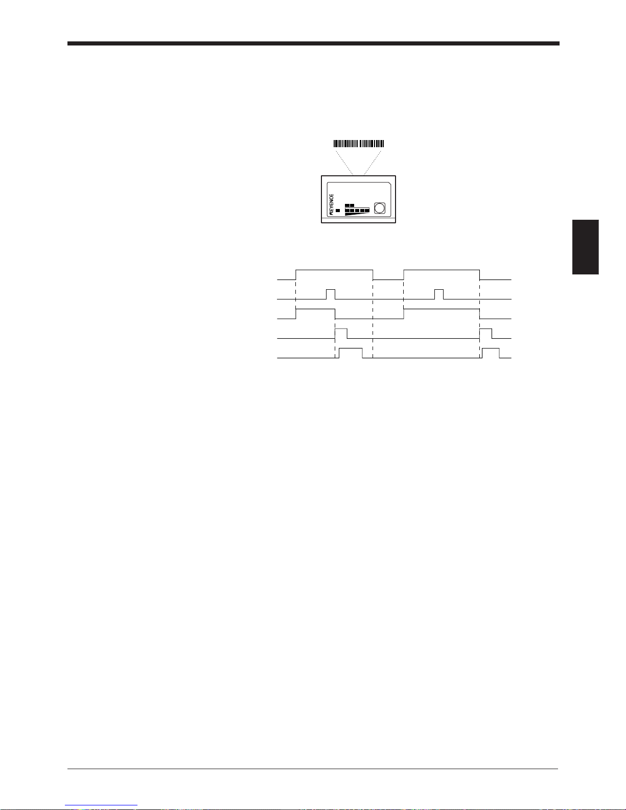
Chapter 3 Functions for Reading Operation
37
3
3.3 Label Orientation Mode
As shown below, this mode allows the unit to read bar codes only in the specified
orientation when bar code labels are moving both in the forward and reverse
orientations.
* Normally, the unit can read bar codes regardless of the orientation.
• An reading error is issued when the unit reads a bar code label running in the
orientation which is not specified.
• The above chart applies to the single label read mode. You can also use this
mode together with the desired multi-label read mode. However, in any case,
the unit reads bar codes running in the specified orientation only.
• You can specify the orientation individually for Codes 1 to 4, such as specifying
“forward orientation” for Code 1, and “reverse orientation” for Code 2.
4 9000000
4 9000000
Reverse
orientation
LASER ON
STB
OK/NG
TIMING
TEST
BL-700
Forward
orientation
OK/NG
NG
<Specified orientation>
<Non-specified orientation>
Trigger input
Bar code
Laser beams
Communication time
OK/NG output
Page 52
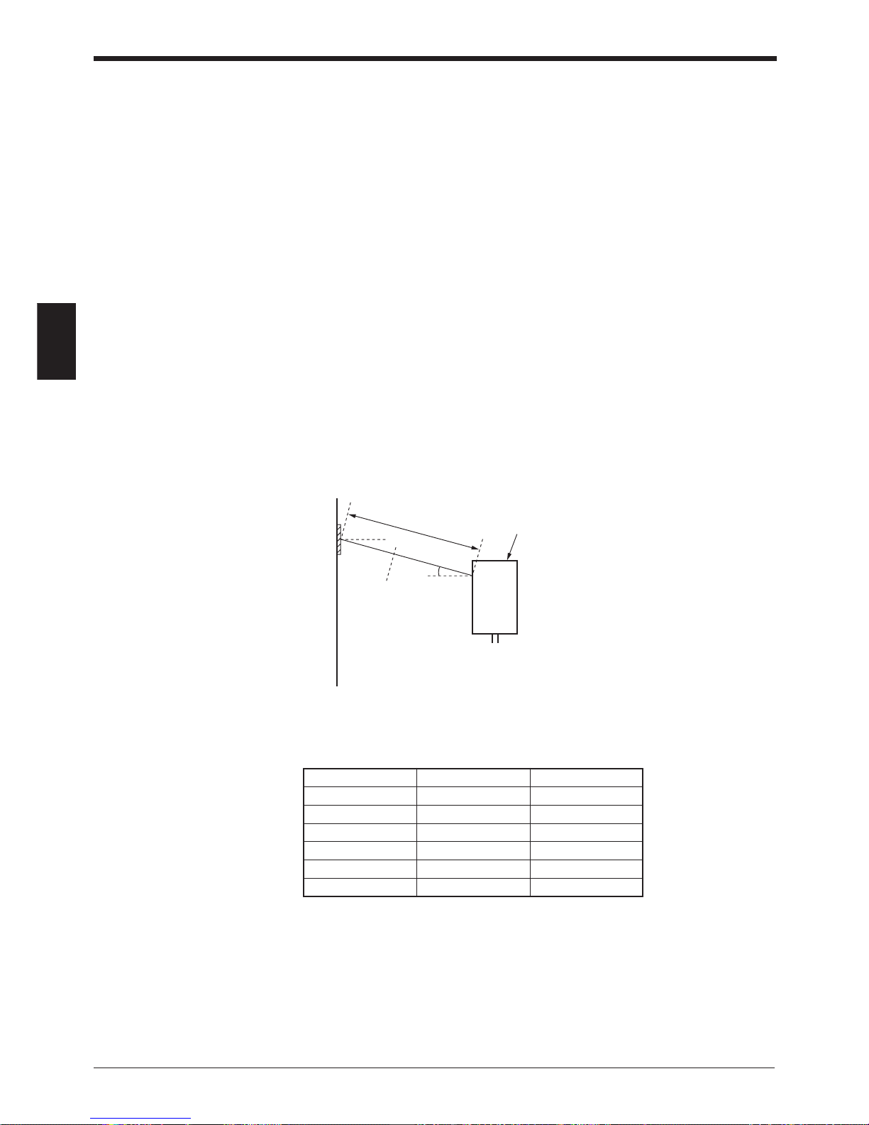
Chapter 3 Functions for Reading Operation
38
3
3.4 Test Mode
Test mode can be used for the bar code reading test. Because trigger input is not
required, this mode allows you to perform a reading test easily. You can select one
of the following 3 methods to enter the test mode.
3.4.1 Reading rate check mode
The unit scans a bar code100 times and analyzes how many times it can decode
the scanned data (reading rate). This mode is useful in the following cases:
• When adjusting the mounting distance and angle
• When verifying the reading stability of the bar code to be used
This mode is enabled when the bar code label stays in the given position.
■ Operation
Follow the instructions below:
1. Hold down the TEST switch for 3 seconds. (Release the switch when one
STABILITY LED illuminates.)
2. The BL-700 then enters the mode in which the laser emission is always ON.
Attempt to use the BL-700 to read bar codes.
3. Depending on the reading rate, the BL-700 displays the STABILITY LEDs as
listed. By checking the display, adjust the reading distance and angle so that
the reading rate reaches the highest level.
10°
Reading distance
Panel surface
* Reading distance = 230 mm (BL-700/701)
380 mm (BL-740/741)
500 mm (BL-780/781)
Reading rate STABILITY LED OK/NG LED
81 to 100 % 5 LEDs ON Green
61 to 80 % 4 LEDs ON Green
41 to 60 % 3 LEDs ON Green
21 to 40 % 2 LEDs ON Green
1 to 20 % 1 LED ON Green
0 % – Red
Page 53
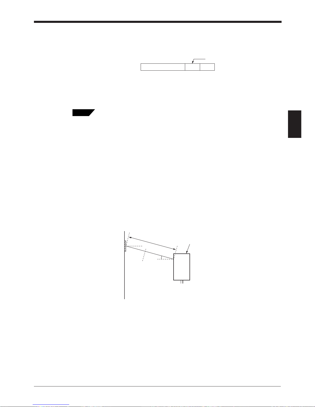
Chapter 3 Functions for Reading Operation
39
3
4. In the test mode, the unit outputs the serial communication data in the following
format every 100 scans. By connecting the BL-700 to a PC and using a BL
setup software terminal, the following data can be displayed on the PC screen.
➮
See P.79 for details of operation.
* ON/NG LED turns ON but OK/NG output does not turn ON.
5. Press the TEST switch again to exit the test mode.
Gently pressing the TEST switch once (for less than 3 seconds) will cause the BL-700 to
read a bar code once. (It also performs serial output and OK/NG output.)
3.4.2 Tact check mode
In this test mode, the unit counts how many scans can be decoded (the decode
count) while reading one bar code.
This mode is useful when testing which line speed can be expected when actually
implementing the BL-700 system on the line.
This is enabled when the bar code label is moving.
■ Operation
Follow the instructions below.
1. Hold down the TEST switch for 5 seconds. (Release the switch when two
STABILITY LEDs illuminate.)
2. The BL-700 then enters the mode in which the laser emission is always ON.
Attempt to use the BL-700 to read bar codes moving on the line.
3. Depending on the decode count, the BL-700 displays the STABILITY LEDs as
listed below 0.2 seconds after the last bar code has passed the laser emission
range. By checking the display, you can recognize how much stability the BL700 ensures during readout. To display the readout count, follow the procedure
in 4 to display the data on the PC screen.
Readout data m
:
Delimiter
* m = 0 to 100 (zero-suppressed)
10°
Reading distance
Panel surface
* Reading distance = 230 mm (BL-700/701)
380 mm (BL-740/741)
500 mm (BL-780/781)
Tips
Page 54
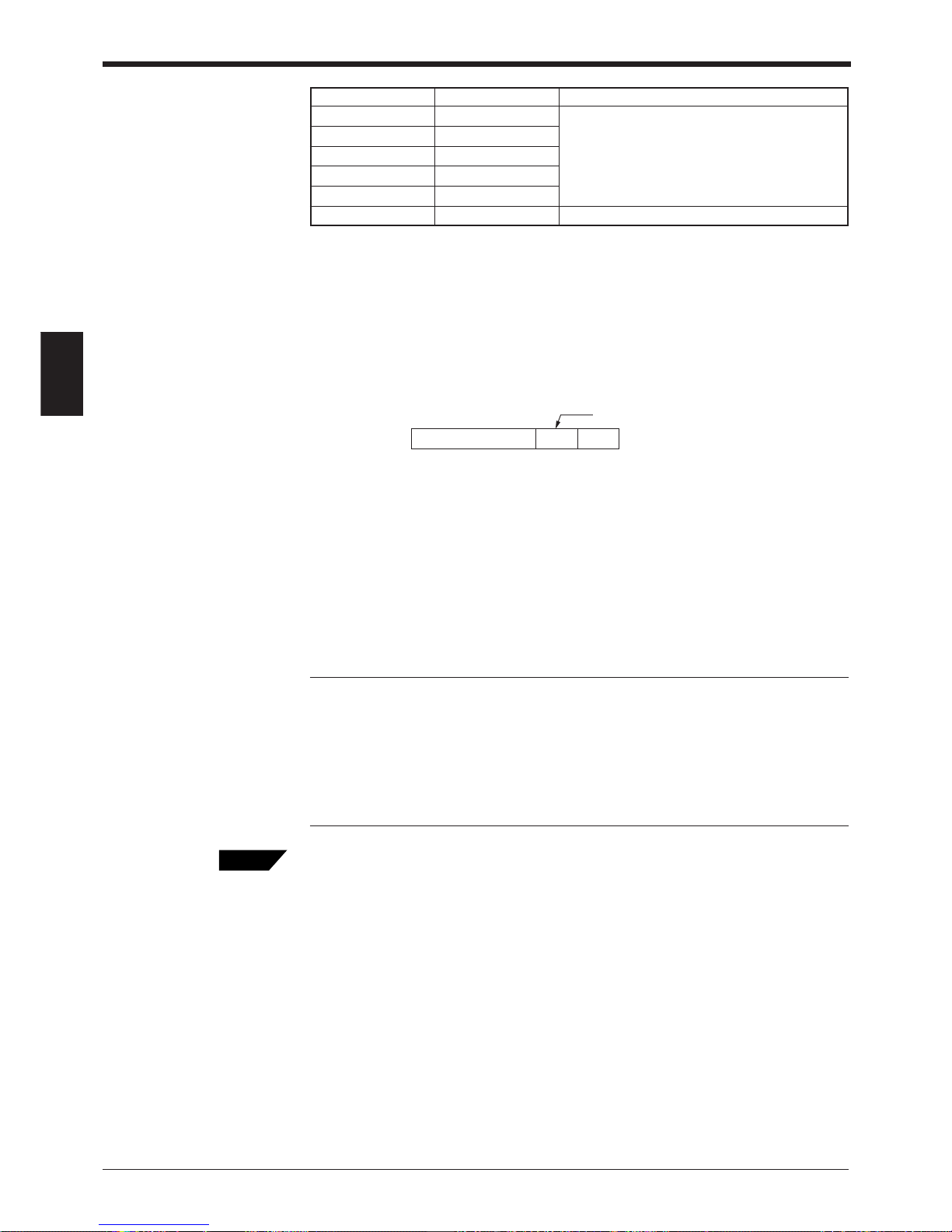
Chapter 3 Functions for Reading Operation
40
3
The BL-700 continues to read the data while the laser beams scan the bar codes.
Thus, the STABILITY LEDs are not ON. When the bar code reading stops for 0.2
seconds, the BL-700 stops scanning and turns ON the STABILITY LEDs.
4. In the serial communication mode, the BL-700 outputs the data in the following
format.
By connecting the unit to a PC and using the BL setup software terminal, the
following data can be displayed on the PC screen.
➮
See P.77 for details of operation.
* ON/NG LED turns ON but OK/NG output does not turn ON.
*A value greater than 9999 cannot be added.
5. When reading the same bar codes continuously within 0.2 seconds, the BL-700
cannot separate the data and continues scanning to add the readout count.
When reading different bar codes within 0.2 seconds, continuous scanning is
enabled.
6. Press the TEST switch again to exit the test mode.
Note 1: When the unit is running in test mode, the laser beam remains on, which
can shorten the laser’s service life.
Select the test mode only when you need to perform a test read. Avoid long emission times.
Note 2: When using the “additional information” (
➮
see P.46 to 47
) in the test
mode, the selected data is added in the same manner as in the normal operation
mode. However, only when selecting the reading rate check mode, the decode
count and scan count are not added to the analyzed results.
To start the test mode, the following alternative method is available in addition to the
method of using the TEST switch.
• Start the test mode using the serial commands (➮ see P.89)
Send the test mode start command (TEST1, TEST2) to start the test command. By
entering TEST1 or TEST2 and pressing [RETURN] from the provided setup
software terminal, the test mode is started.
• Start the test mode by turning the trigger input ON (➮ see P.58)
Turning the timing input ON enables the setting to start the test mode. When this is
set, the trigger input cannot function normally. Also, startup using the serial command
is disabled.
Use the setup software to perform the settings.
• Start the test mode by turning power ON (➮ see P.58)
Setting is available to start the test mode immediately at power-ON.
Use the setup software to perform the settings.
Readout data m
:
Delimiter
* m = 1 to 9999 (zero-suppressed)
Reading rate STABILITY LED OK/NG LED
100 or more 5 LEDs ON
50 to 99 4 LEDs ON
10 to 49 3 LEDs ON
5 to 9 2 LEDs ON
1 to 4 1 LED ON
0–Red
Tips
Green (The readout count equals or exceeds
the matching decode count.)
Red (The readout count is below the matching
decode count.)
Page 55
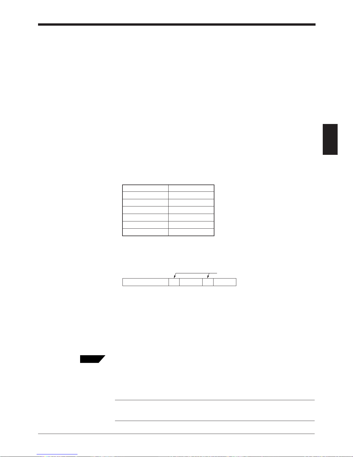
Chapter 3 Functions for Reading Operation
41
3
3.4.3 Online test mode
When the BL-700 always reads the bar codes, the reading stability can be displayed in real time using the STABILITY LEDs. This mode is called online test
mode.
■ Setting
1. To set the online test mode, send the following command from the BL setup
software terminal. To use the terminal,
see P.77
.
Command to be sent: #TEST1
Send-data: OK
When OK is returned to the command sent, it indicates the mode is set.
This setting is valid only when power is ON. The setting data is reset after
power is turned OFF.
2. According to the setting, start the BL-700 to read bar codes normally. In the
online test mode, the send-data and STABILITY LEDs are displayed after the
trigger input turns OFF.
3. The STABILITY LEDs turn ON as shown below, indicating how many times the
unit can read the data correctly.
4. The BL-700 sends the data in the following format.
The information on the scan count during one trigger-ON and the correct readout count is appended to the data. The scan count includes the cases where no
bar code is set.
5. To quit the online test mode, send the following command.
Command to be sent: #QUIT
Send-data: OK
When OK is returned to the command sent, it indicates the mode is canceled.
Online test mode operation is the same as when setting the following from the BL-700
setup software. To save the online test mode setting in the BL-700, set the following using
the setup software.
• Data adding function — Add decode count.
Add scan count.
• STABILITY LED — Display the data.
Note: When you try to enter the test mode by turning on trigger input, you cannot
use the serial command to enter the test mode.
Commands should be entered in all uppercase characters.
Reading rate STABILITY LED
100 or more 5 LEDs ON
50 to 99 4 LEDs ON
10 to 49 3 LEDs ON
5 to 9 2 LEDs ON
1 to 4 1 LED ON
0–
Readout data m s/
:
Delimiter
*m = 1 to 9999: Readout count (zero-suppressed)
s = 1 to 9999: Scan count (zero-suppressed)
Tips
Page 56
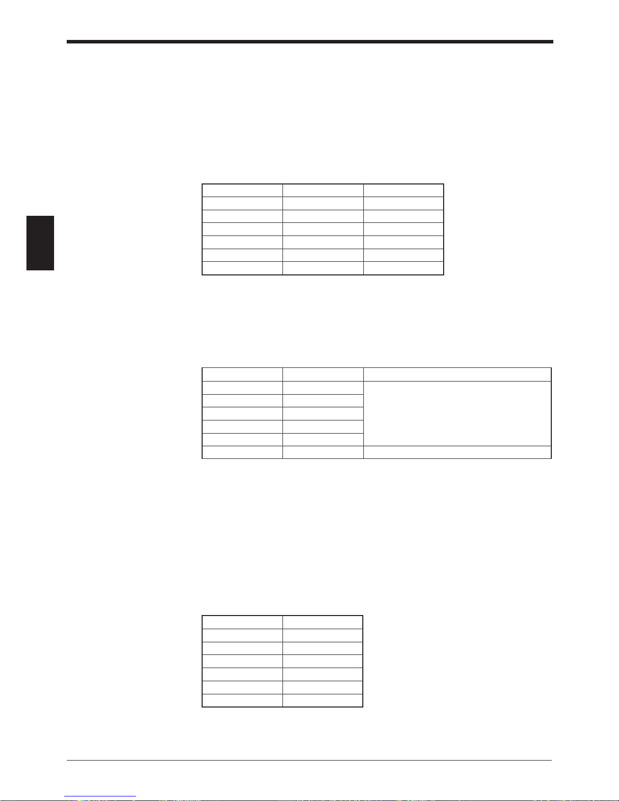
Chapter 3 Functions for Reading Operation
42
3
Decode count STABILITY LED
100 or more 5 LEDs light
50 to 99 4 LEDs light
10 to 49 3 LEDs light
5 to 9 2 LEDs light
1 to 4 1 LED light
0—
3.5 STABILITY LEDs
STABILITY LEDs allow you to easily check reading stability and operation status.
Indication of reading stability
■ When reading rate check mode is selected
STABILITY LEDs light according to the reading rate shown in the table below.
Although, in the test mode, the unit does not output an OK/NG signal, the OK/NG
LED lights as below. (Comparison to the preset data is not performed.)
■ When tact check mode is selected
STABILITY LEDs light according to the scan count (decode count), which indicates
the number of successful reads, as shown in the table below.
Although, in the test mode, the unit does not output an OK/NG signal, OK/NG LED
lights as below. (Comparison to the preset data is not performed.)
■ When normal read mode is selected
When you select multi-label read mode 1 or 2 (
➮
See P.33 to 34
), or the send
mode is set to “after trigger input” (
➮
See P.32
), or you select the decode count
adding function (
➮
See P.47
), STABILITY LEDs light according to the decode
count as shown in the table below.
However, If you do not select “use STABILITY LED” in the setup software (
➮
See
P.68
), STABILITY LEDs do not light in normal read mode.
ON/NG output (ON/NG LED) turns on/off normally according to the result of a
comparison to the preset data.
The following also appears in the online test mode.
Reading rate STABILITY LED OK/NG LED
81 to 100% 5 LEDs light Green
61 to 80% 4 LEDs light Green
41 to 60% 3 LEDs light Green
21 to 40% 2 LEDs light Green
1 to 20% 1 LED light Green
0% — Red
Decode count STABILITY LED OK/NG LED
100 or more 5 LEDs light
50 to 99 4 LEDs light
10 to 49 3 LEDs light
5 to 9 2 LEDs light
1 to 4 1 LED light
0—Red
Green (decode counts are equal to or greater
than the preset match count)
Red (decode counts are less than the preset
match count)
Page 57
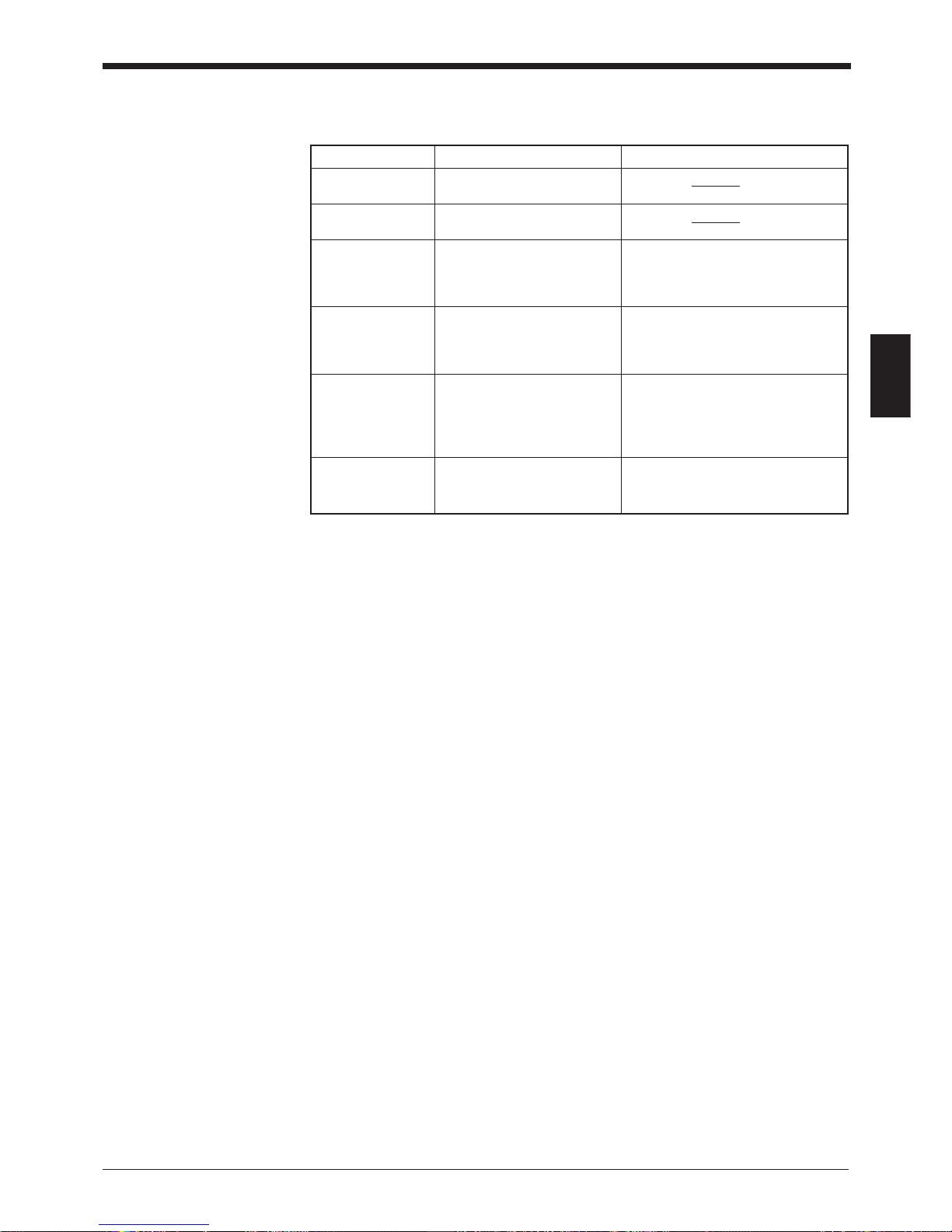
Chapter 3 Functions for Reading Operation
43
3
■ Unit operation status display
STABILITY LEDs indicate the following information in addition to reading stability.
Operation status STABILITY LED display Action to be taken
Power-on LEDs turn on sequentially
from the bottom.
During setup All the LEDs flash.
(
➮
see P.92
)
Waiting for setting The 1st, 3rd and 5th LEDs In this status, send the settings from
data send/receive from the top flash the setup software. (Hold down the
(
➮
see P.73
)simultaneously. TEST switch for 8 seconds to set the
data.)
Laser forced OFF The bottom LED flashes. When resetting laser forced OFF
(
➮
with LOCK
(with UNLOCK command), the unit
command,
returns to the initial operation at
see P.90
) power-on.
Unit error Either of the 2nd, 3rd, or 4th The unit may have failed or supply
LEDs from the top flashes. voltage may have dropped. If supply
voltage is normal, the unit may have
failed. Contact the nearest
KEYENCE office or distributor.
PLC link error The top LED flashes. The error is reset by pressing the
(
➮
see P.117
) TEST switch again.
➮
See P.116 for troubleshooting.
Page 58

Chapter 3 Functions for Reading Operation
44
3
3.6 Preset Function (Compare with:)
3.6.1 What is the preset function?
The BL-700 can store one bar code as preset data. It compares the preset data to
the bar code data actually read and outputs an OK/NG signal to whether there is a
match.
Using the BL-700 preset function, you can prevent the wrong products from entering the line without using a PC.
If no preset data is registered, the unit outputs OK when it successfully reads a bar
code and NG when it fails to read a bar code.
➮
See P.30 to 37 for output timing.
Use the setup software and serial command to register the preset data (
➮
See
P.68 and P.101
).
Note: The bar code actually read can be compared to the preset data only in the
single label read mode.
➮
See P.136 if you want to use CODE93.
➮
See P.137 if you want to use CODE128.
Page 59
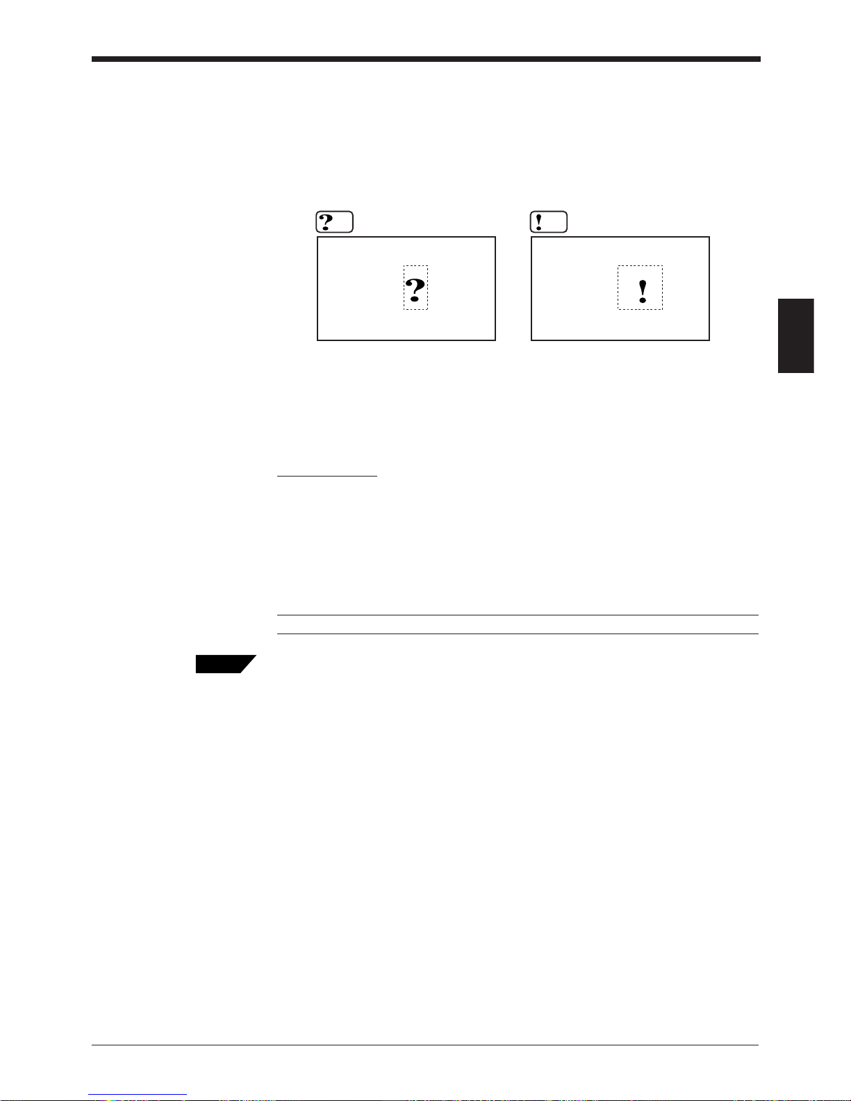
Chapter 3 Functions for Reading Operation
45
3
3.6.2 Wildcard Symbols (“!” and “?”)
Using “!” and “?” in the preset data allows for flexible settings.
?: Does not define numeric values (characters) of certain digit(s) of the bar code.
!: Ignores numeric values and symbols within the dot box and recognizes the bar
codes as the same group.
Setting examples
1. “ABC?” ABCD (OK), ABC3 (OK), ABC (NG), ABCDE (NG)
2. “ABC!” ABCD (OK), ABC3 (OK), ABC (OK), ABCDE (OK), AB (NB)
3. “?????” Any 5-digit bar code will be OK.
4. “!CDE” ABCDE (OK), 3CDE (OK), CDE (OK), ABBDE (NG), ADE (NG)
5. “A!E” ABCDE (OK), A3CE (OK), ABCD (NG), AE (OK)
Note: You can use “!” only once in the setting.
If you do not register preset data, “!” is automatically registered. Therefore, when the unit
successfully reads a bar code, “OK” is output; when the unit fails to read, “NG” is output.
49123456
49125256
4912AB56
49123456
4912C
4912
When using “?” data as “4912??56”, 2
digits positioned in “??” can contain
any numeric values (or characters),
expanding the allowable range.
Identifies all the bar codes to be OK as
long as the beginning or ending strings
match.
When using “!” as “4912!”, any bar
code which begins with “4912” will be
OK. When using “!” as “!4912”, any bar
code which ends with “4912” will be
OK.
Tips
Page 60
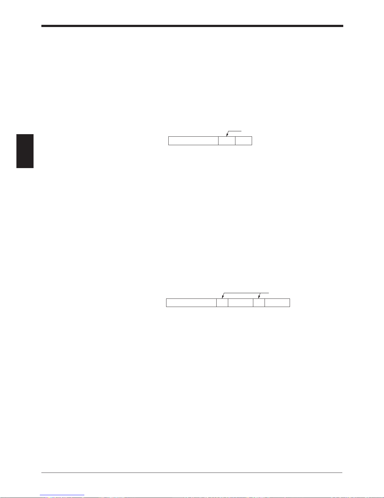
Chapter 3 Functions for Reading Operation
46
3
3.7 Additional Information
When sending the bar code data, you can add the following data to the readout
data.
Additional information types
■ Decode match count add function
Adds the number of successful scans during one bar code reading (decode count)
to the end of the readout data (up to 9999 count). However, this decode count is
never less than the preset decoding match count.
This function can be used to check reading stability and code label quality.
* The value is zero-suppressed.
When using this function, output turns on at a different time from normal operation.
• In single label read mode, output turns on after one bar code has been read
(after trigger input turns off). Even if you set the data send to “after read”, the
data is forced sent after trigger input turns off.
• In multi-label read mode 1, a bar code passes across the laser beam’s field,
after repeat read time, and is finally output.
• In multi-label read mode 2 or 3, operation is the same as when you do not use
the decode match count adding function.
■ Scan count add function (valid only when using the read count add func-
tion)
Adds the number of scans, including when no bar code exists, to the end of the
decode count (up to 9999).
* The value is zero-suppressed.
Readout data d
:
Delimiter
d = [Decoding match count] to 9999: Decode count
Readout data d s/
:
Delimiter
s = 1 to 999 (zero-suppressed)
Page 61
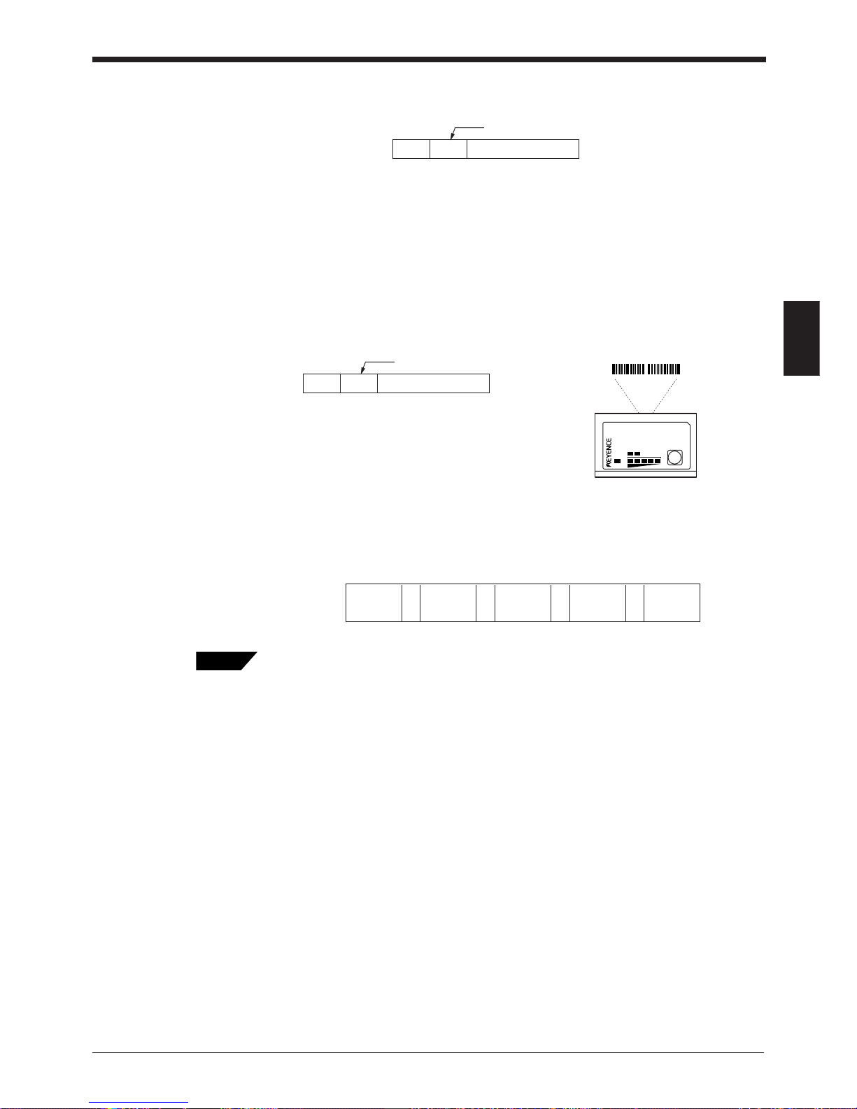
Chapter 3 Functions for Reading Operation
47
3
■ Code type add function
Adds the bar code type before the readout data .
■ Label orientation add function
Adds the orientation of bar code travel before the readout data.
* If an read error occurs, this information is not added.
Order of additional information
If you select to include all the additional information functions, they appear in the
following order:
You can change the delimiter as desired (one character), except the delimiter of the scan
count.
Readout datat
:
Delimiter
t = 0 : CODE39
1: ITF
2: Industrial 2of5
3: Codabar
4: EAN/UPC (A•E)
5: CODE 128
6: COOP 2 of 5
7: Read error
8: CODE93
Readout datar
:
Delimiter
4 9000000
4 9000000
Reverse
orientation
LASER ON
STB
OK/NG
TIMING
TEST
BL-700
Forward
orientation
r = F : Forward
R: Reverse
Code type
Readout
data
Scan
count
Decode
match count
Label
orientation
::::
Tips
Page 62
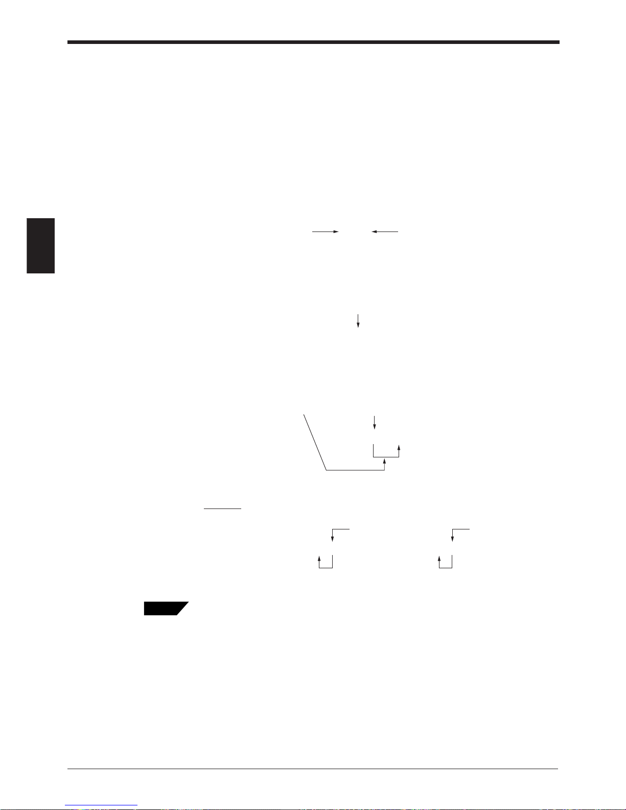
Chapter 3 Functions for Reading Operation
48
3
3.8 Max. Code Length (Designated Digit ) Output Function
This function allows you to output the designated digit(s) as desired from the
readout bar code data. For example, from bar code data “49123456”, you can
extract “1234” for output.
Setting digits to be output
Set the digits to be output as shown below. Individually set the digits for codes 1 to
4.
1. Set the direction to designate.
* Set from which direction you want to start counting.
2. Set how many digits you want to designate for output starting from the designa-
tion start digit in (2) (designation effective digits).
* The actual setting order is (1) (3) (2).
3. Set from which digit you want to begin designation (destination start digit).
Example
Designating and outputting “34” from bar codes “158423421” and “58423421”
Designate 2 digits starting from 3rd digit by counting reversely.
• Regardless of the designated direction, the data is output forward in the communica-
tion application.
• When the bar code group includes those having different digits, take special care on
the designated direction when setting the digits to be output.
• When comparing to the preset data, all the digits of the bar code are used.
49123456
Forward Reverse
49123 456
5th digit by counting forward
49123456
3 digits starting from 5th digit by counting forward
158423421 58423421
Tips
Page 63

Chapter 4
Setup Software
4.1 Installing the Setup Software ............................................52
4.1.1 Installing setup software ........................................................ 52
4.1.2 Installation procedure ............................................................ 52
4. 2 Setup Software Operating Procedure ............................... 54
4.2.1 Operating procedure .............................................................. 54
4.2.2 Description on each setup screen ......................................... 55
4.2.3 Outline of operation ............................................................... 56
4.3 Details of Setup ................................................................... 58
4.3.1 Setup procedure .................................................................... 58
4.3.2 Reading/Saving/Printing File ................................................. 71
4.4 Sending/Receiving Settings ..............................................75
4.5 Using Monitor ...................................................................... 79
4.6 List of Error Messages ....................................................... 82
4.7 Example of Printing from the Setup Software .................. 83
Page 64
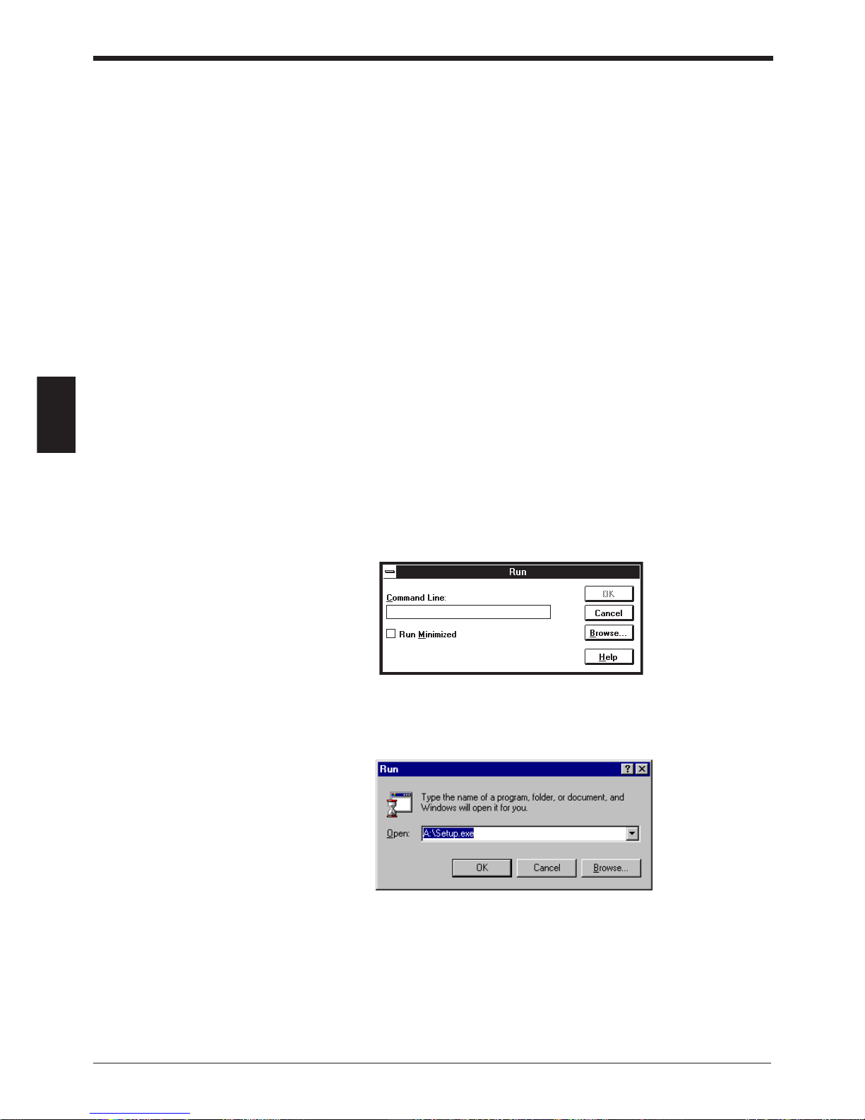
Chapter 4 Installing the Setup Software
50
4
4.1 Installing the Setup Software
This section describes the operating environment of the setup software and the
software installation.
4.1.1 Installing setup software
■ Hardware requirements
IBM PC/AT 100% compatible
CPU: 486 SX or higher
Memory: 4 MB or more
Floppy disk drive: 3.5 inch floppy disk drive (1.44 MB compatible)
Display: Resolution 640 x 480 or higher
Serial port: A minimum of one RS-232C port is required.
■ OS requirements
• MS-Windows 3.1
• MS-Windows 95
4.1.2 Installation procedure
1. Insert the BL-700 setup software system disk into the floppy drive.
2. Perform the following procedure.
• Windows 3.1:
Execute “Run...” in the icon menu of the program manager.
• Windows 95:
Select “Run” from the "Start" menu.
Page 65
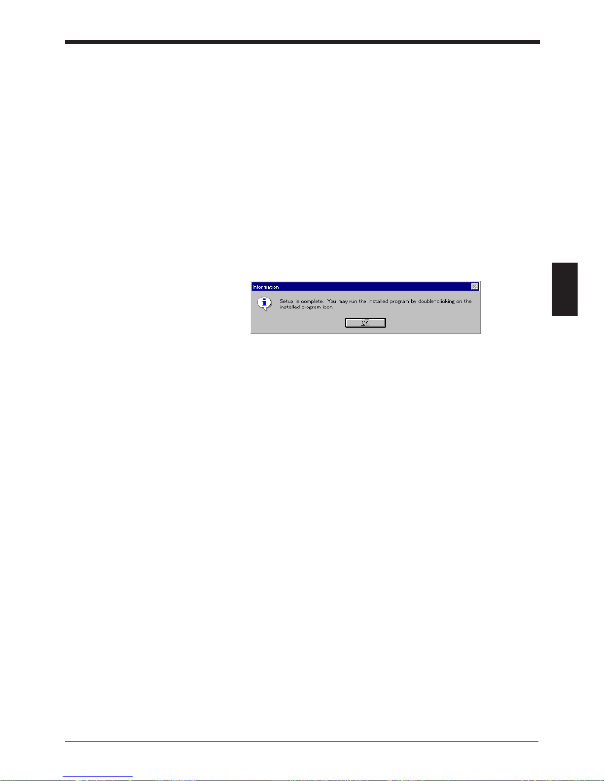
51
Chapter 4 Installing the Setup Software
4
3. Run the “SETUP” file from the floppy disk drive.
(This step is common to both the Windows 3.1 and Windows 95.)
Type in as follows:
A: \SETUP
4. The BL-700 setup software installer starts. Follow the instructions in the install
window. (Typically, the installation procedure can be completed simply by
pressing [Next (N)] twice.)
5. The setup software is normally installed in the following directory:
C: \KEYENCE\BLSET
If this directory is correct, click on [Next (N)]. If you wish to change the directory,
click on [Browse (R)..], and select the desired directory.
6. When installation starts, the file copy process is displayed as a graph. When the
installation is completed, the following message appears.
7. For Windows 3.1, double-click on the [BL] icon in the [KEYENCE] group to start
the setup software.
For Windows 95, start the program from the "Start" menu.
Page 66

Chapter 4 Installing the Setup Software
52
4
4.2 Setup Software Operating Procedure
4.2.1 Operating procedure
To set up the BL using the setup software, follow the procedure below.
1. Connect the BL to the host computer using a null modem cable.
For the recommended cable, see P. 12 and P. 19.
2. Start the BL setup software.
3. In “Select Model” of “File/etc...”, select the model to be connected (“BL-700”).
4. Select a setup item, and set it to the desired condition.
5. Before sending the updated settings to the BL-700, click on [COM PORT] to
match the communication parameters of the personal computer with the current
settings of the BL.
The default settings of the BL are as follows:
• Baud rate: 9600 bit/s
• Data length: 7 bit
• Parity: Even
• Stop bit length: 1 bit
• PLC link: Don’t use
• Multi-drop link: Disabled
Immediately after you purchase the BL, set [COM PORT] to the above settings.
If you do not know the current settings of the BL, press the BL TEST switch for
approximately 8 seconds. The 1st, 3rd and 5th STABILITY LEDs from the top
will flash simultaneously. The settings listed above are fixed. Execute (6) “Send/
receive settings”.
6. Click on [Transfer] to send the updated settings to the BL.
(The current settings of the BL can also be read.)
7. Select [FILES] to save or print the settings, as required.
8. After the setup procedure is completed, click on [Exit] to close the setup soft-
ware.
Page 67
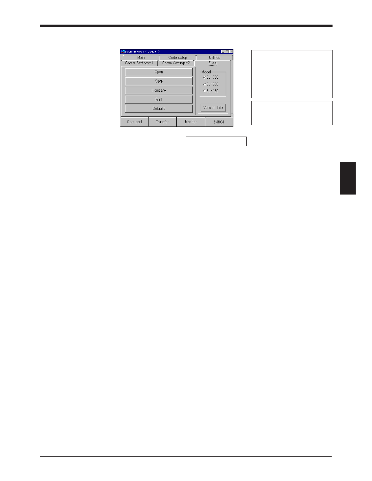
53
Chapter 4 Installing the Setup Software
4
4.2.2 Description on each setup screen
Main (Operation setting:)
• Read mode and its setup
• Data addition function
• Decoding match count
• Read error code
• Scanning method, trigger ON/OFF command
Comm Settings-1 (Communication parameters 1:)
• Baud rate, data length, parity, stop bit
• RTS/CTS protocol
• Multi-drop, ID number
Comm Settings-2 (Communication parameters 2:)
• Communication protocol
• Header and terminator
• PLC link settings
• Delimiter, semi-delimiter
Code setup (Bar code setting:)
• Type of bar code to be read, number of digits
• Fixed-digit output function, label orientation function
Utilities:
• OK/NG output ON time
• Preset data registration
Files...:
Saving, readout and printout of settings, selection of model
COM Port:
Sets the communication parameters (baud rate, etc.) of the host computer according to the settings of the BL before communication starts between the BL and host
computer.
TRANSFER:
Sends updated settings to the BL, or reads the current settings of the BL.
MONITOR:
Checks if the BL can operate normally.
EXIT:
Quits the BL setup software.
Displays the name of the setup file
currently being edited. If the file has
been read from the setup file, the file
name is specified as “File: ...”. If the
file has been read from the BL, the
file name is marked with “BL”. If the
file name is the initial setting, “default”
is displayed.
If the file name has been changed
from the initial setting (the condition
immediately after it is read from the
file), “changed” is displayed.
Select the model to be set.
Page 68
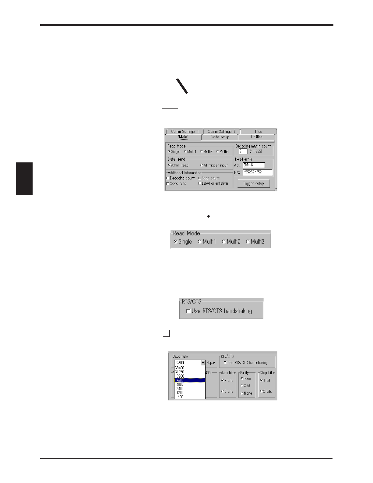
Chapter 4 Installing the Setup Software
54
4
4.2.3 Outline of operation
This section describes the basic operations of the BL setup software.
To enter settings, place the mouse pointer on the item to be changed, and click the
left mouse button.
■ Clicking on • • • (tabs)
Used to select the item to be changed.
■ Clicking on ●● (radio button)
Used to select any of several options.
The selected item is marked with ●●.
■ Clicking on a ■■ (box)
Used to select whether to enable or disable this function.
To enable this function, the ■■ mark is checked with “ ”. (For the Windows Ver. 3.1,
it is checked with “x”.)
■ Clicking on ▼ (arrow)
Used to select any of several options.
•
▲
Mouse pointer
Page 69
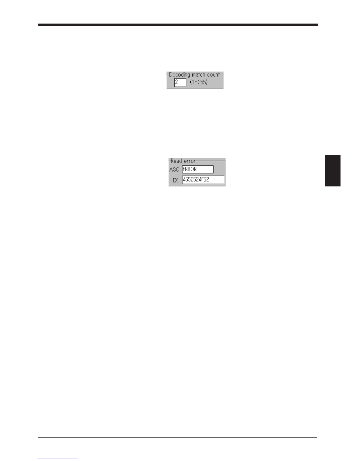
55
Chapter 4 Installing the Setup Software
4
■ Entering a value
After clicking in the frame, enter a value using the keyboard.
If the entered value exceeds the setting range, an error message is displayed.
➮
See P.82.
■ Entering characters
When you click in the frame labeled “ASC”, you can enter characters using the
keyboard.
When you click in the frame labeled “HEX”, you can enter characters using hexadecimal numbers (00 to 7F). This function is used to enter control characters (00 to
21h ASCII codes, such as [CR] and [STX]).
Page 70
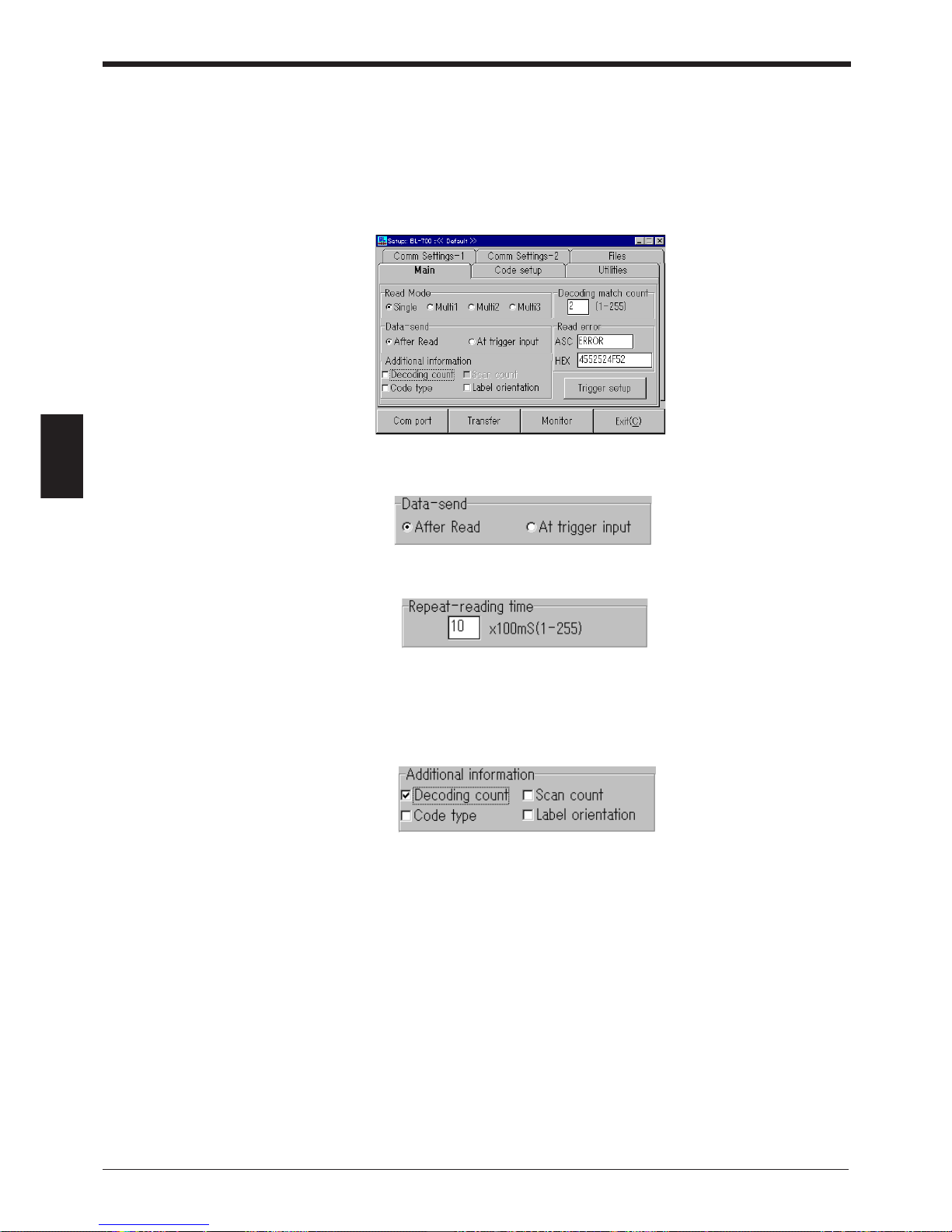
Chapter 4 Installing the Setup Software
56
4
4.3 Details of Setup
4.3.1 Setup procedure
Main (Operation setting)
Set read mode, additional data function and trigger input.
1. When “Single” is selected in “Read Mode”, the following appears:
When “Multi 1” or “Multi 2” is selected, the following appears:
Set the data to a number from 1 to 255 (100 ms to 25.5 s).
When “Multi 3” is selected, these setting menus will not appear.
2. Multiple data can be selected in “Additional data function”. “Scan count” ap-
pears only when “Decode count” is selected.
Page 71
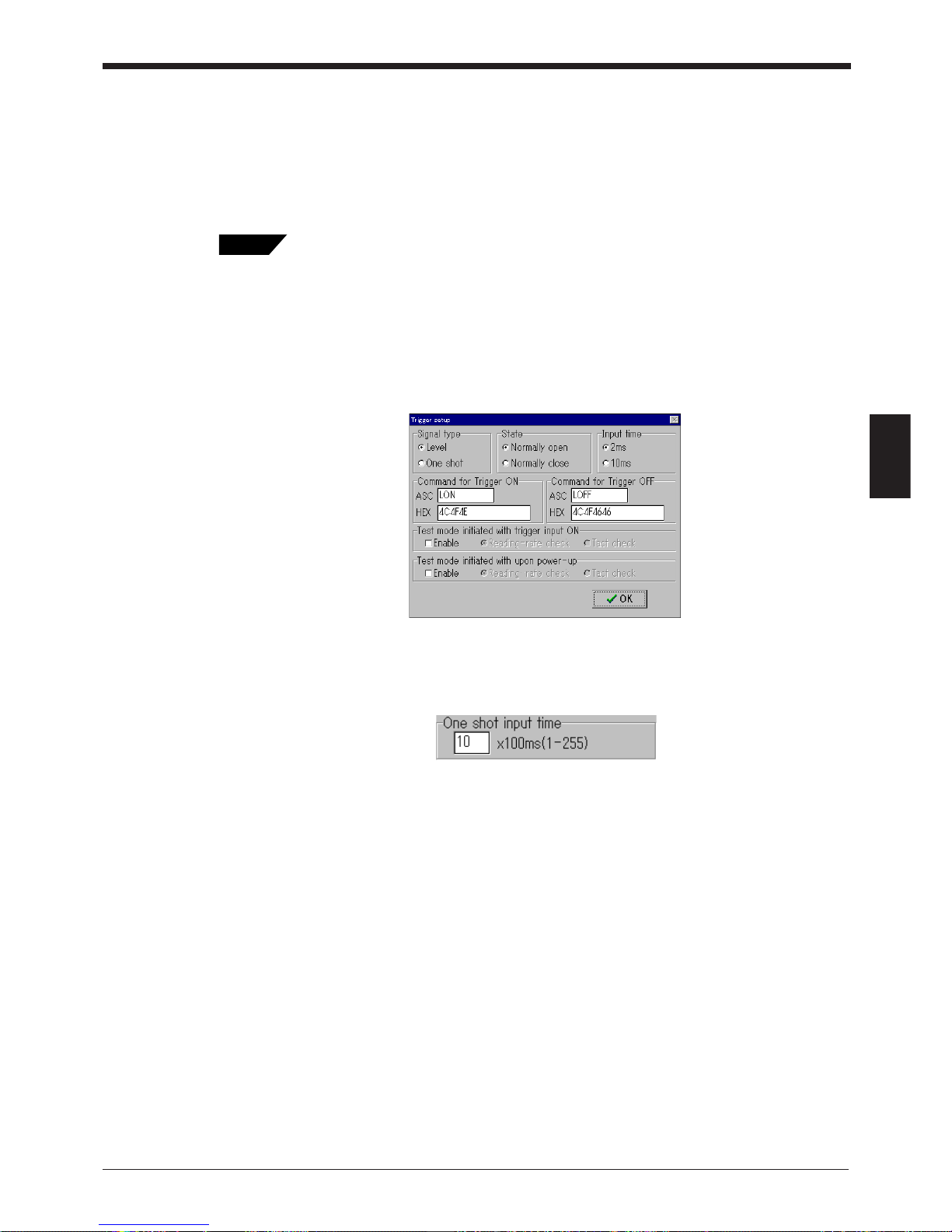
57
Chapter 4 Installing the Setup Software
4
3. Enter the “Read error code” from the keyboard. The code can be changed as
desired (within 8 characters).
Normally, the initial setting (ERROR) should be used as provided.
If a blank is specified for the setting, the BL-700 will not send the read error
code.
4. Click “Trigger input setting” to set the trigger input.
• Read mode ➮ P.35 to 38
• Data transmission trigger ➮ P.34
• Double reading prevention time ➮ P.35 to 36
• Decoding match count ➮ P. 32
• Additional data function ➮ P.48 to 49
• Read error code ➮ P.89
Trigger input setting
Set the trigger input, scanning method and trigger ON/OFF command.
1. For the scanning method, select either “Level signal trigger” or “One-shot signal
trigger”. If “One-shot signal trigger” is selected, the scanning time setting menu
also appears.
Set the scanning time to a number from 1 to 255 (100 ms to 25.5 s).
Tips
Page 72
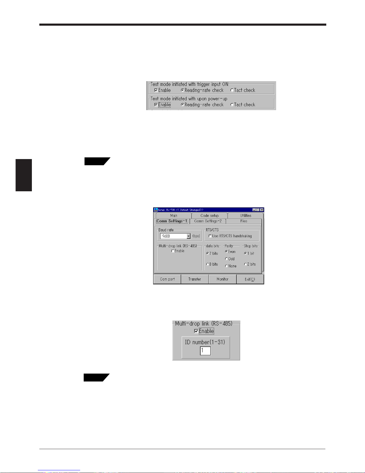
Chapter 4 Installing the Setup Software
58
4
2. Enter the “Trigger ON/OFF command” from the keyboard. The command name
can be changed as desired (within 8 characters).
Normally, the initial setting (LON, LOFF) should be used as provided.
3. Enable either “Start the test mode with trigger input ON” or “Start the test mode
at power-on”.
When “Start the test mode with trigger input ON” is enabled, the trigger input
cannot be used during normal operation.
If both functions are selected, “Start the test mode with trigger input ON” has
priority.
• Scanning method ➮ P.32 to 33
• Trigger ON/OFF command ➮ P.91
• Starting the test mode ➮ P.40 to 43
Comm Settings-1 (Communication parameters 1)
Set the communication parameters.
When “Multi-drop (RS-485)” is enabled, the ID number setup menu also appears.
Set the ID number to a value from 1 to 31. “RTS/CTS protocol” is then disabled.
• RTS/CTS protocol ➮ P.88
• Multi-drop ➮ See the Multi-drop Controller N-400 User’s Manual.
Tips
Tips
Page 73
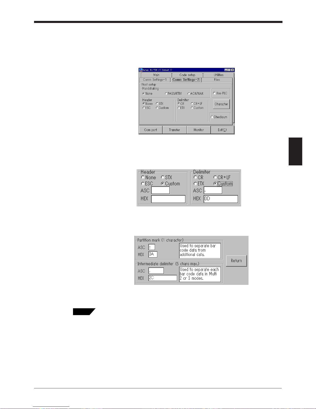
59
Chapter 4 Installing the Setup Software
4
Comm Settings-2 (Communication parameters 2)
The following settings depend on the use of “PLC link”.
■ When the PLC link is not used
The menu screen allows setup of communication protocol, header and terminator.
1. Select the header and terminator from the items provided. When the header
and terminator are set, only the read data format can be changed.
When “Set” is clicked, the following menu appears:
Enter the desired data from the keyboard up to a maximum of 5 characters.
2. When “Character” is clicked, the following menu appears:
Enter the delimiter and semi-delimiter from the keyboard and then click
[Return].
• (Communication) protocol ➮ P.87 to 88
• Header, terminator ➮ P.89
• Checksum ➮ P.140
• Delimiter character ➮ P.48 to 49
• Semi-delimiter ➮ P.37 to 38
Tips
Page 74
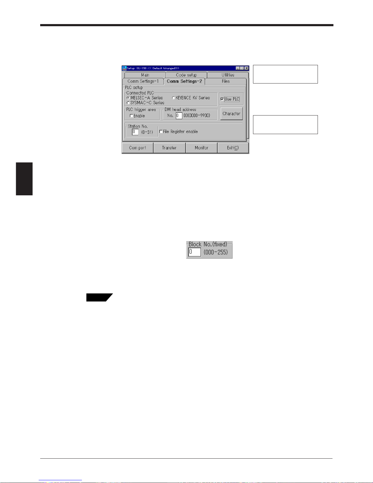
Chapter 4 Installing the Setup Software
60
4
■ When using the PLC link
To enable the "Use PLC", set each item as follows:
• Set “Connected PLC”, “DM head address” and “Station No.”.
To set “DM head address”, enter a value (0000 to 9900) using the keyboard.
• To send a trigger signal to the BL series when the PLC link is enabled, set “PLC
trigger area”.
• To use “File Register”, set “File Register” to “Enable”. When “File Register” is
enabled, the following screen appears. The “File Register” can be used with the
Mitsubishi MELSEC-A series only.
Enter the block number (000 to 255) of the file register using the keyboard.
• PLC link ➮ P.106
• PLC trigger area ➮ P.113 to 115
• DM head address ➮ P.111
• File register ➮ P.107
The setting of the station
number is not displayed
when “KV Series” is selected.
The setting of the file register
is displayed only when
“MELSEC-A” is selected.
Tips
Page 75
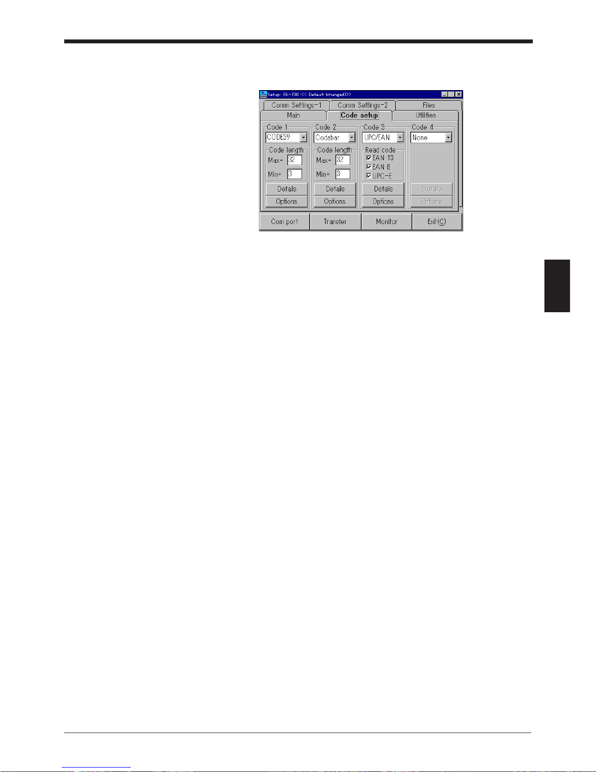
61
Chapter 4 Installing the Setup Software
4
Code Setup (Bar code setting)
Set the readout digits, detail data and special functions for each code type.
1. Set the code.
Set the type and number of digits of the bar codes to be read in codes 1 to 4.
If four different types of codes are specified in 1 to 4, the BL-700 can read 4
types of bar codes without changing the settings.
2. Click [Details] to set “Send start/stop character” and “Check digit test”.
3. Click [Options] to set “Fixed-digit output function” and “Label orientation func-
tion” (
➮
see P.69
).
* Be sure to set the ITF digits to an even number.
* For UPC/EAN, set whether each of the 13-digit EAN, 8-digit EAN and UPC-E is
enabled to read.
* CDE128 varies depending on the type of the start/stop character (CODE-A to
CODE-C)
CODE-A/B: 1 to 31
CODE-C: 1 to 64
The start/stop character and check digit are not included in the number of digits.
Also, FUN 1 to 4 (function codes), SHIFT and CODE-A to CODE-C are not
included in the number of digits.
Page 76
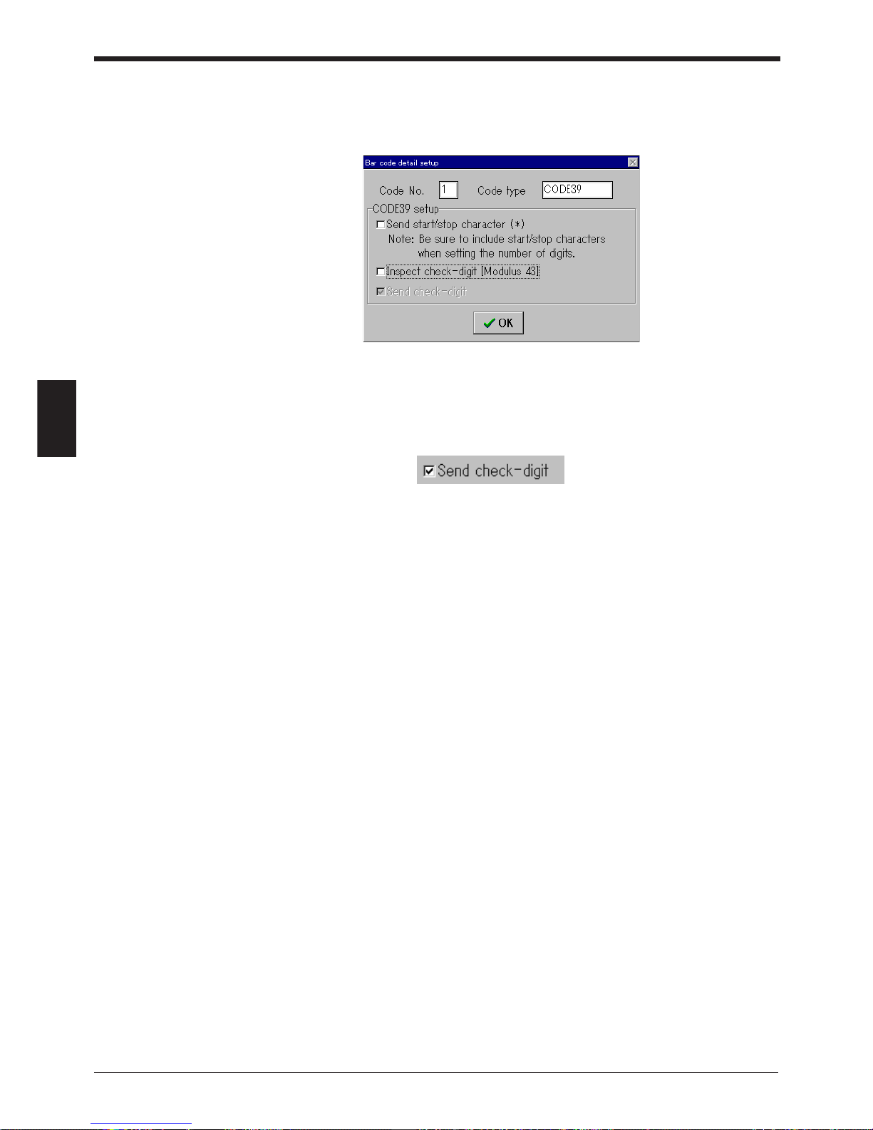
Chapter 4 Installing the Setup Software
62
4
CODE 39 detail settings
When “CODE 39” is set for any of the 4 codes in the bar code setting and then
[Detail] is clicked, the following screen appears.
1. When “Send start/stop character (*)” is set, the BL-700 adds an * (asterisk) to
the data and sends it.
2. When “Check digit test” is set, the following appears:
When “Send check digit” is set, the BL-700 sends the data including the check
digit.
To calculate the check digit, the BL-700 uses Modulus 43.
Page 77
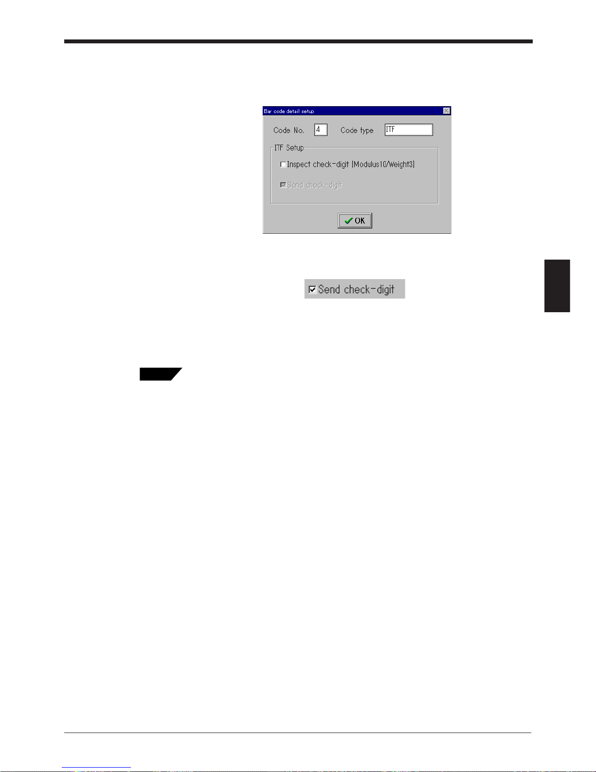
63
Chapter 4 Installing the Setup Software
4
ITF detail settings
When “ITF” is set for any of the 4 codes in the bar code setting and then [Detail] is
clicked, the following screen appears.
1. When “Check digit test” is set, the following appears:
When “Send check digit” is set, the BL-700 sends the data including the check
digit.
To calculate the check digit, the BL-700 uses Modulus 10/3 weight.
When reading the standard distribution code (bar code on the carton box), set 14 digits
or 16 digits in the bar code setting and set “Check digit test”.
Tips
Page 78
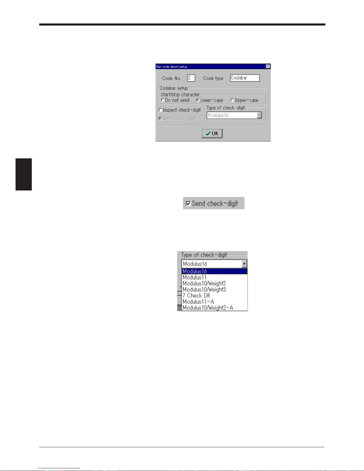
Chapter 4 Installing the Setup Software
64
4
Codabar detail settings
When “Codabar” is set for any of the 4 codes in the bar code setting and then
[Detail] is clicked, the following screen appears.
1. When “Lowercase” or “Uppercase” is set in “Start/stop character”, the BL-700
adds “A, B, C, D” (lowercase or uppercase) to the data and sends it.
2. When “Check digit” is set, the following appears:
When “Send check digit” is set, the BL-700 sends the data including the check
digit.
Select the type of check digit to be used.
Page 79
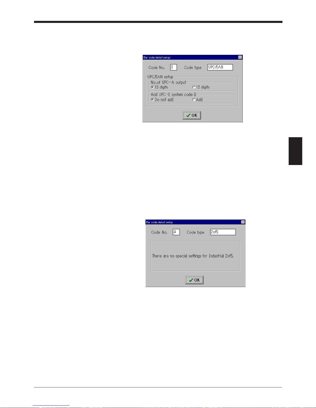
65
Chapter 4 Installing the Setup Software
4
UPC/EAN detail settings
When “UPC/EAN” is set for any of the 4 codes in the bar code setting and then
[Detail] is clicked, the following screen appears.
1. “UPC-A output digits” sets whether the 13-digit or 12-digit output format is used
when reading the UPC-A data.
2. When “Yes” is set in “Add UPC-E system code [0]”, the BL-700 adds 0 to the
beginning of the system code and sends the code. (This parameter appears
only when “UPC-E” is set to enable reading in the bar code setting.)
* The check digit setting is not provided on the screen but the BL-700 calculates it
using the modulus 10/3 weight. (The data is sent.)
(Industrial) 2of5, COOP2of5 and CODE93 detail settings
When “2of5”, “COOP2of5” or “CODE93” is set for any of the 4 codes in the bar
code setting and then [Detail] is clicked, the following screen appears.
For industrial 2of5, COOP2of5, and CODE93, detail setting parameters are not
provided.
Page 80
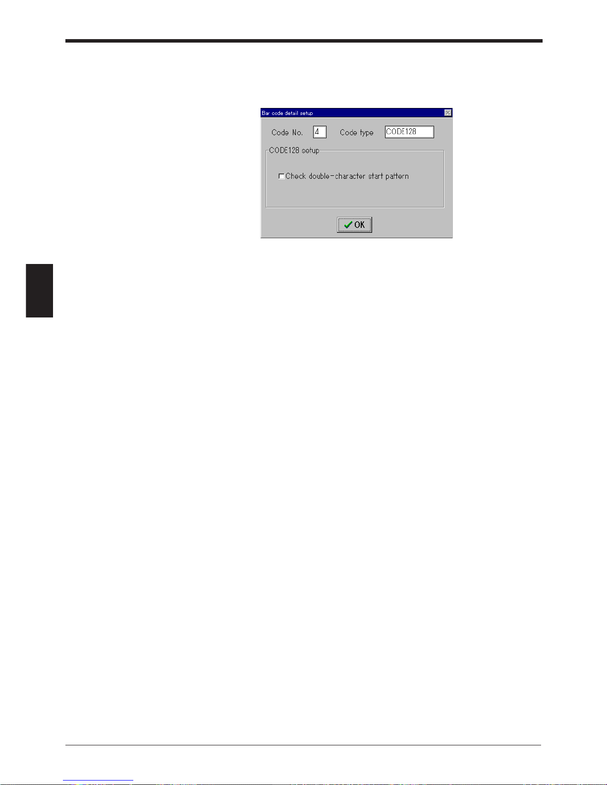
Chapter 4 Installing the Setup Software
66
4
CODE128 detail settings
When “CODE128” is set for any of the 4 codes in the bar code setting and then
[Detail] is clicked, the following screen appears.
1. “Double character start pattern” is defined in the UCC/EAN-128 standard. This
is a combination of the start character (CODE-A to CODE-C) and FUN1 (function code 1). The UPC/EAN-128 bar code must start with the double character
start pattern.
If this is not set, the BL-700 will not be able to read the data.
* The check digit setting is not provided on the screen but the BL-700 calculates it
using the modulus 103 weight. (The data is not sent.)
Page 81
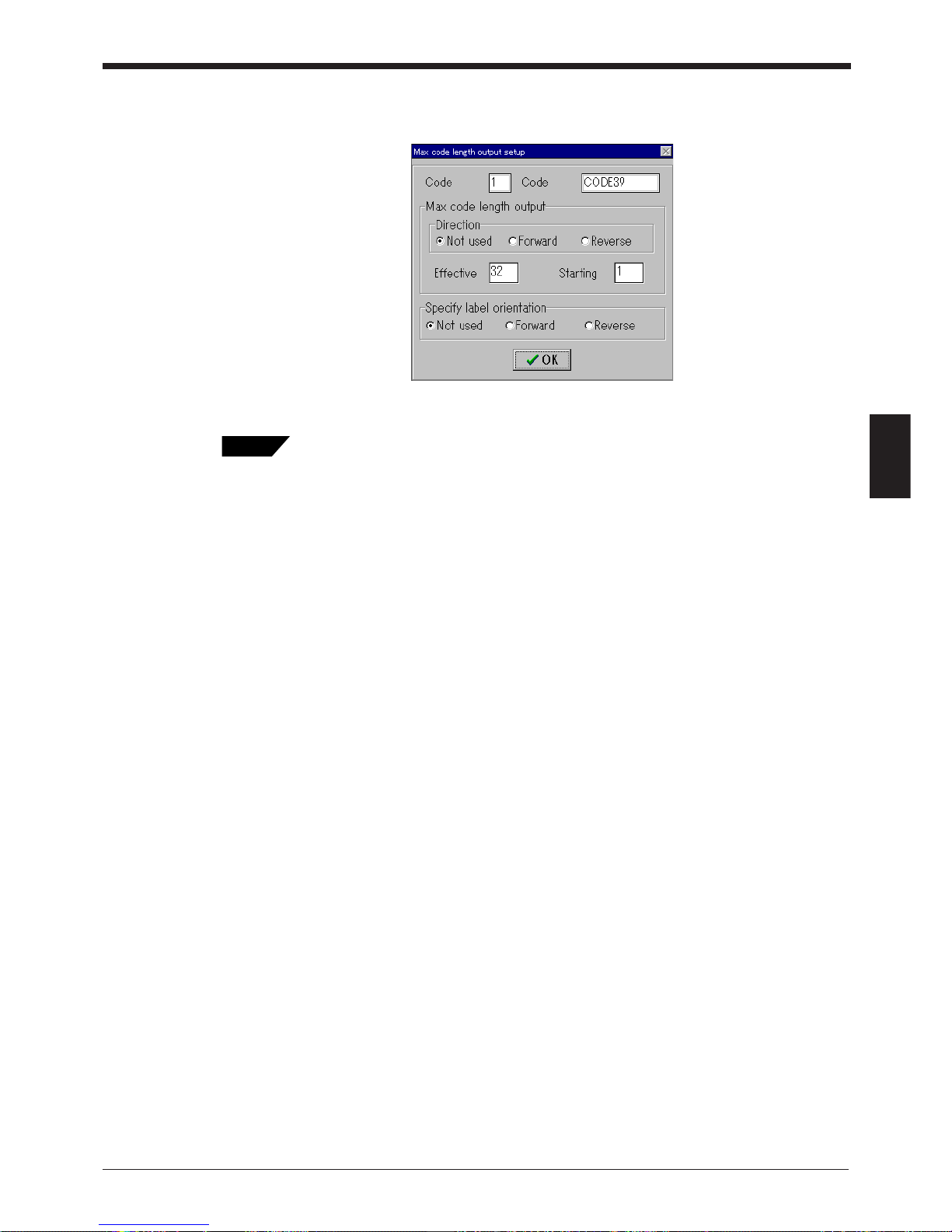
67
Chapter 4 Installing the Setup Software
4
Options setting
When [Options] is clicked in the bar code setting, the following screen appears.
Set “Max code length output function” and “Label orientation function”.
• Fixed-digit output function ➮ P.50
• Label orientation mode ➮ P.39
Tips
Page 82
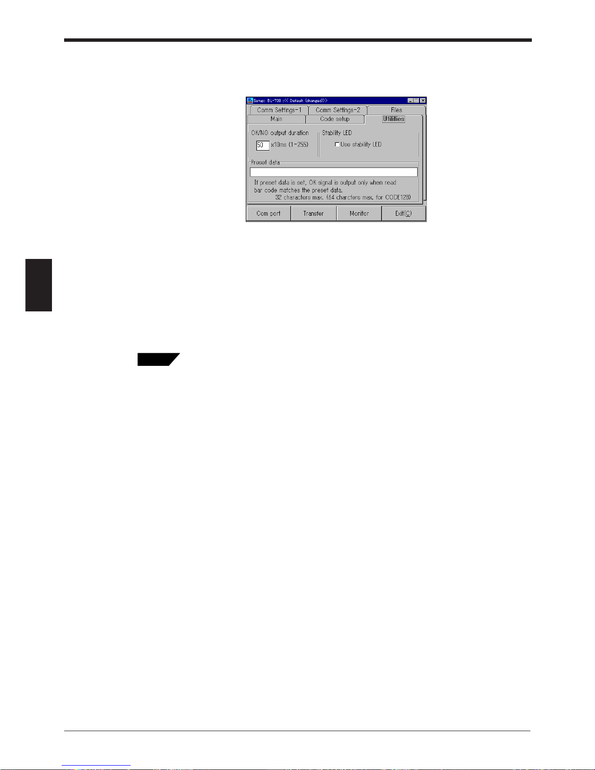
Chapter 4 Installing the Setup Software
68
4
Utilities settings
The settings of OK/NG output ON time and preset data registration are available.
1. To set “OK/NG output ON time”, enter a numeric value from the keyboard from
1 to 255 (10 ms to 2.55 s).
2. When “Display STABILITY LEDs” is set, the BL-700 displays the STABILITY
LEDs which indicate the reading stability during normal reading operation.
3. To set “Preset data”, enter the preset data to be registered from the keyboard.
Normally, the data should be set within 32 characters. If CODE-C is set for
CODE128, up to 64 characters can be set.
• OK/NG output ON time ➮ P.32
• STABILITY LED ➮ P.44
• Preset data ➮ P.46
Tips
Page 83
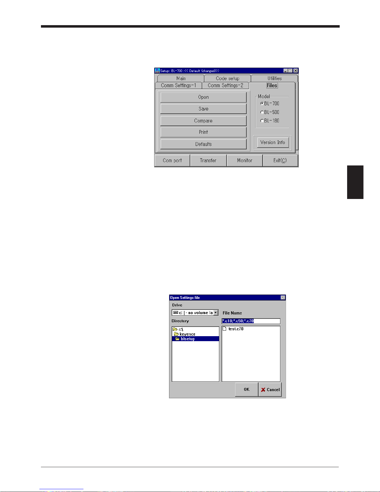
69
Chapter 4 Installing the Setup Software
4
4.3.2 Reading/Saving/Printing File
The FILES screen is used to save updated settings in a file, to read a saved setting
file, and to print the contents of a setting file.
• Model: Select the model to be set.
• Open: Reads a saved setting file.
• Save: Saves updated settings in a file.
• Compare: Compares the settings currently edited with a file previously saved.
• Print: Prints contents of a setting file.
• Defaults (Initialize settings): Restores updated settings to the default settings.
• Version info: Displays the version information of this software.
Reading a previously saved setting file
1. To read a previously saved setting file, click on [Open]. The following screen will
appear.
2. When you click on [OK] after selecting a file, the selected file can be opened.
Page 84
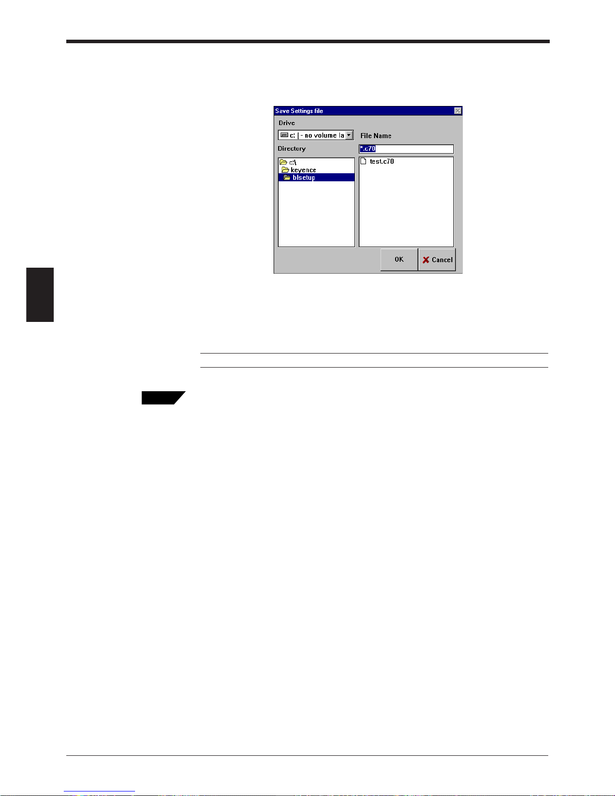
Chapter 4 Installing the Setup Software
70
4
Saving updated settings in a file
1. To save updated settings in a file, click on [Save]. The following screen will
appear.
2. Click on the file name entry field, and enter a file name using the keyboard.
Specify a file name within eight characters. Be sure to add the extension “NCF”.
After entering the file name, click on [OK] to save the file.
Note: This software cannot accept a long file name in Windows 95.
When the saved setting file is sent to the BL-700, the name of the file is simultaneously
sent to the BL-700. When you read the settings of the BL-700 using this software, the file
name is also read. It is convenient for maintenance since you can find the file that stores
the settings.
To enter a file name, use alphanumerics (letters and numbers) only. Otherwise, the file
name cannot be sent to the BL-700, because it can only recognize alphanumerics. To send
a file name, be sure to enter the file name using alphanumerics and then save it. (If the file
name is not saved, it cannot be sent to the BL-700.)
Tips
Page 85
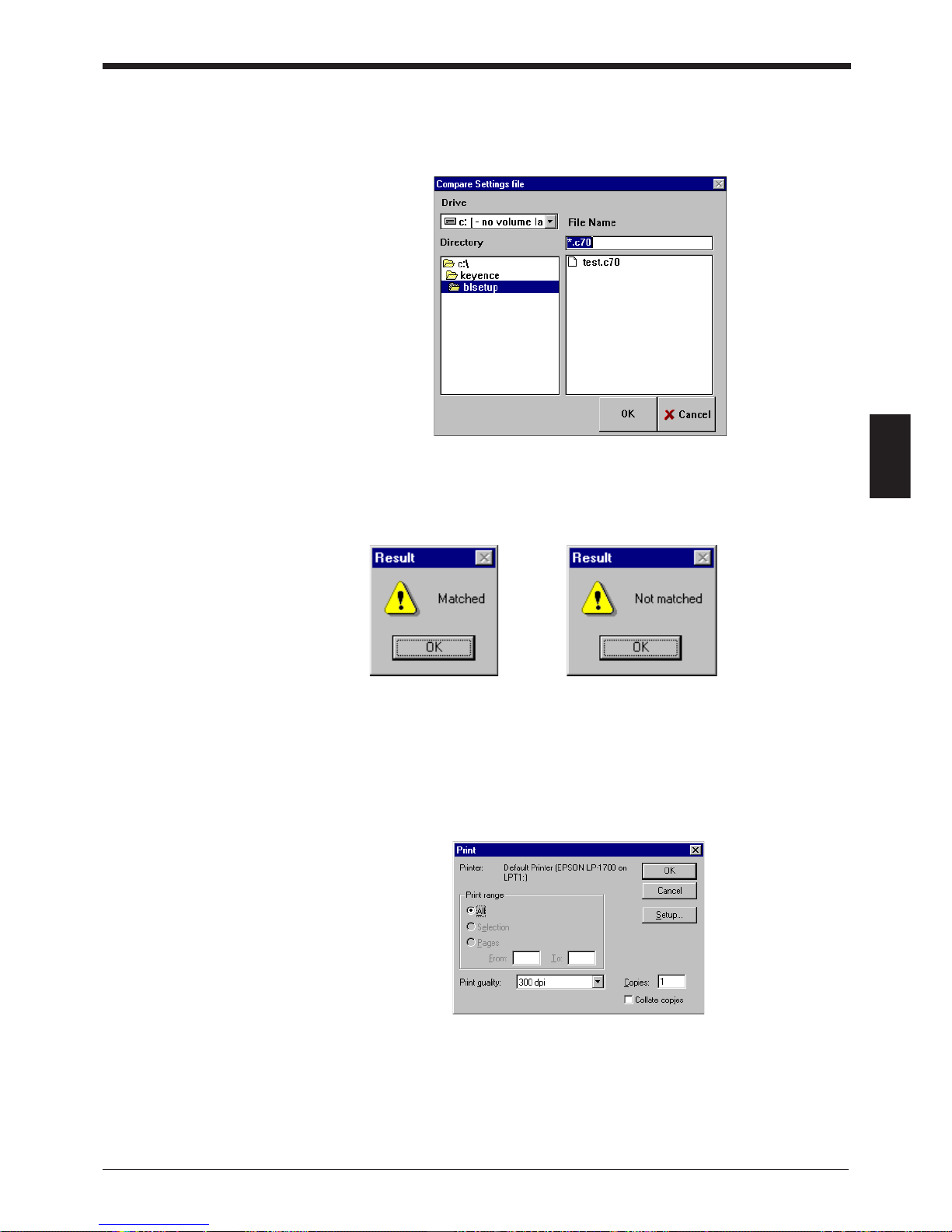
71
Chapter 4 Installing the Setup Software
4
Comparing the settings currently edited with a saved file
1. To compare the settings currently edited with the setting file previously saved,
click on [Compare].
2. Select a file to be compared, and click on [OK]. Then, the system compares the
selected file with the settings currently edited, and displays the result.
Matched Not matched
Printing contents of a setting file
1. To print settings, click on [Print]. The following screen will appear.
2. Adjust “Printer Setup” as required, and click on [OK]. Printing will then start.
Page 86
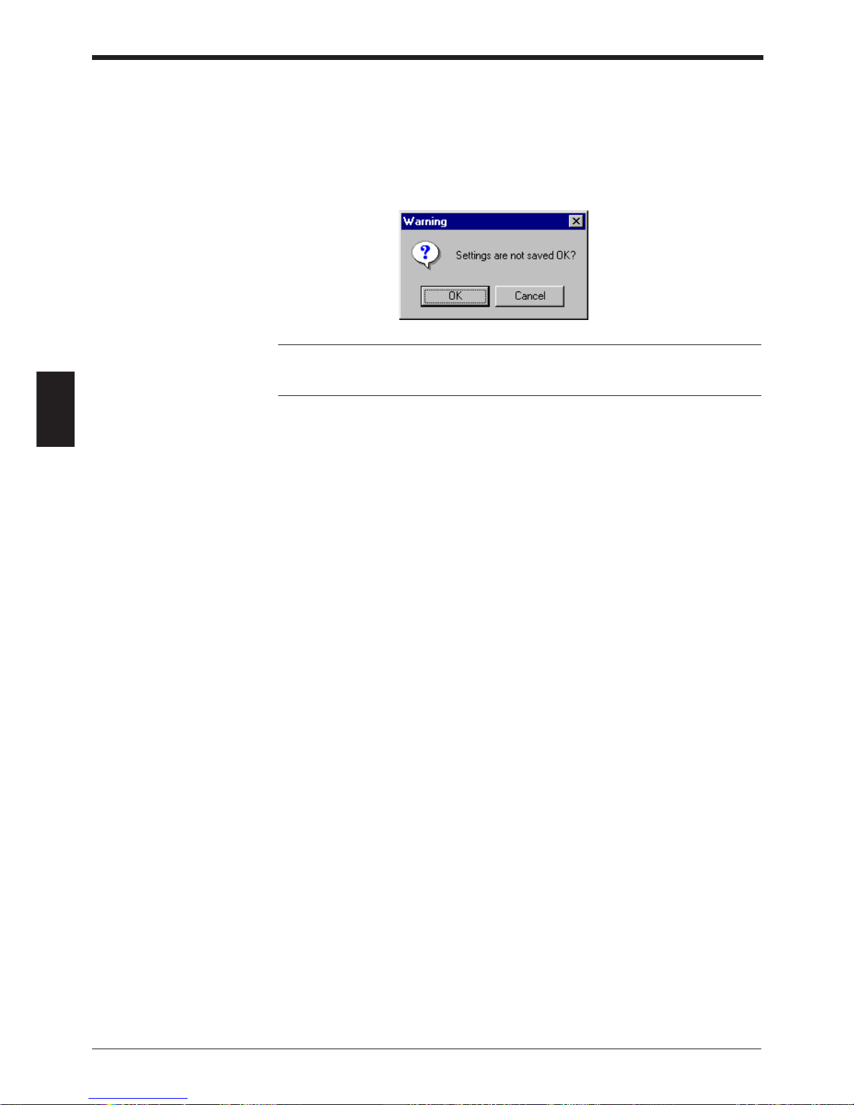
Chapter 4 Installing the Setup Software
72
4
Restoring the settings currently edited to the default (initial) settings
1. To restore the settings currently being edited to the default settings, click on
[Defaults (Initialize settings)].
2. If you try to initialize the settings currently being edited without saving them, the
following message appears. If you wish to execute initialization, click on [OK].
Note: The initialization procedure described in this section is used to initialize the
settings being edited with the setup software. The settings on the BL-700 cannot
be initialized.
Page 87
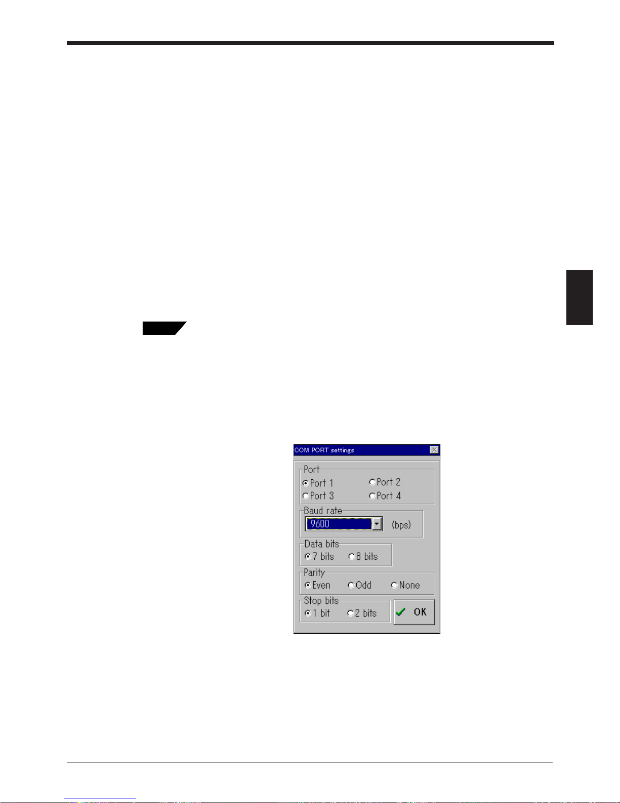
73
Chapter 4 Installing the Setup Software
4
4.4 Sending/Receiving Settings
To send the updated settings to the BL-700 and to read the settings from the BL700, perform the following procedure.
Sending updated settings to the BL-700
To send updated settings to the BL-700, perform the following procedure.
1. Press the BL-700 TEST switch for 8 seconds. When the 1st, 3rd and 5th STA-
BILITY LEDs from the top flash simultaneously, the communication protocol is
temporarily set as indicated below (this status is called “setting data send/
receive waiting status”).
• Baud rate: 9600 bits/s
• Data length: 7 bits
• Parity: Even
• Stop bit length: 1 bit
• PLC link: Disabled
• Multi-drop link: Disabled
If you know the current communication parameter settings of the BL-700, this step is not
necessary. You can send data to the BL-700 by setting the communication parameters of
the host computer using [COM PORT] so that they conform to the current settings of
the BL-700. However, if PLC link is enabled, you cannot send data to the BL-700 without
performing this step because the handshaking protocol is set for PLC link only.
2. Click on [COM PORT] to set the communication parameters of the host com-
puter according to the values listed in the step 1. (above procedure). Select an
RS-232C port, and click on [OK].
Tips
Page 88
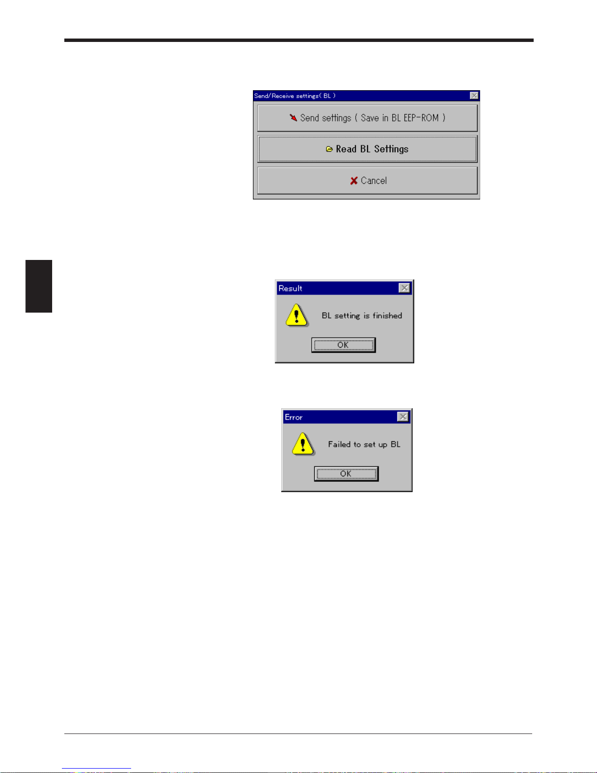
Chapter 4 Installing the Setup Software
74
4
3. Click on [Send settings (Save in BL EEP-ROM)]. The updated settings are then
sent to the BL-700.
4. If the settings were successfully sent to the BL-700, the following message
appears.
If the host computer failed to send the data to the BL-700, the following message appears.
If this message is displayed, check the following points:
• Check that [COM PORT] is set as shown in (1) when the 1st, 3rd and 5th
STABILITY LEDs from the top flash simultaneously (when in “setting data
send/receive waiting status”).
• Check that the power to the BL-700 is ON.
• Check that the RS-232C cable pin assignment of the BL-700 is the same as
that of the host computer.
Page 89
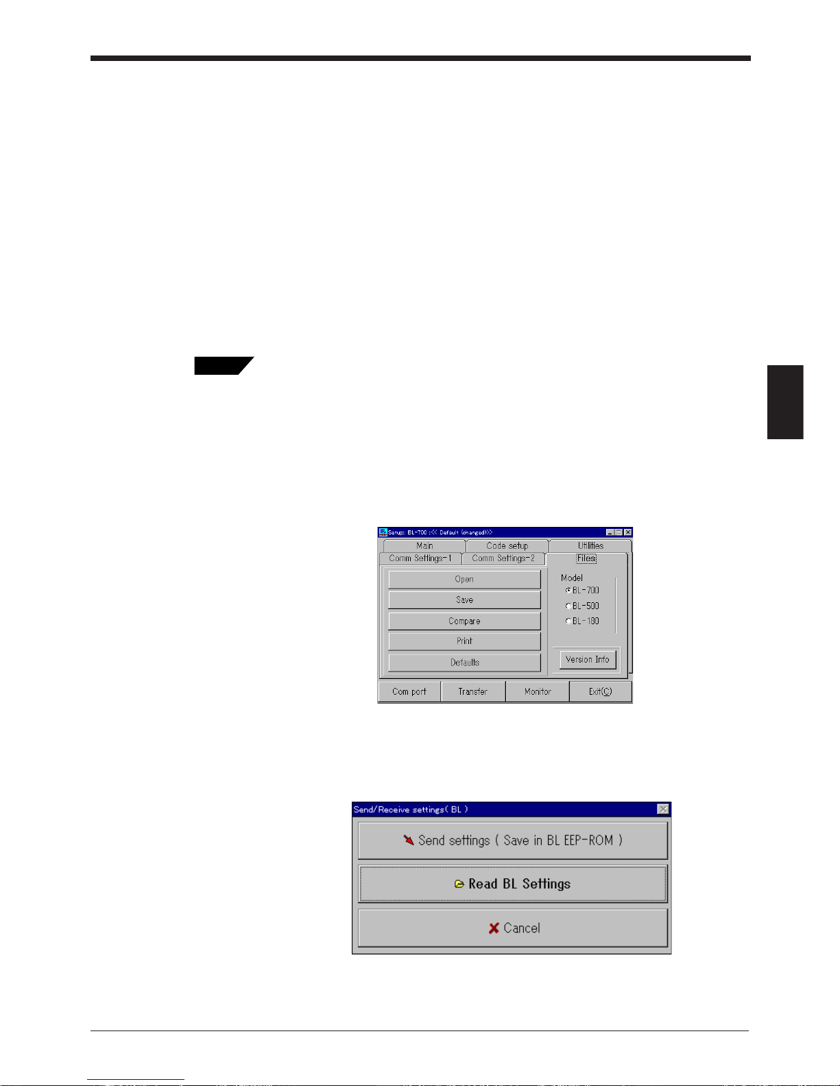
75
Chapter 4 Installing the Setup Software
4
Reading the current settings of the BL-700
To read the current settings of the BL-700, perform the following procedure. (This
procedure is almost the same as the procedure for sending settings.)
1. Press the BL-700 TEST switch for 8 seconds. When the 1st, 3rd and 5th STABILITY LEDs from the top flash simultaneously, the communication protocol is
temporarily set as indicated below (this status is called “setting data send/
receive waiting status”).
• Baud rate: 9600 bits/s
• Data length: 7 bits
• Parity: Even
• Stop bit length: 1 bit
• PLC link: Disabled
• Multi-drop link: Disabled
If you know the current communication parameter settings of the BL-700, step 1. is not
necessary. You can send data to the BL-700 by setting the communication parameters of
the host computer using [COM PORT] so that they conform to the current settings of
the BL-700. However, if PLC link is enabled, you cannot send data to the BL-700 without
performing step 1., because the handshaking protocol is set for PLC link only.
2. Click on [COM PORT] to set the communication parameters of the host com-
puter according to the values listed in step 1. Select an RS-232C port and click
on [OK].
3. Click on [Send settings (Save in BL EEP-ROM)].
When you click on [Read BL settings], the settings of the BL-700 can be read
on the host computer.
Tips
Page 90
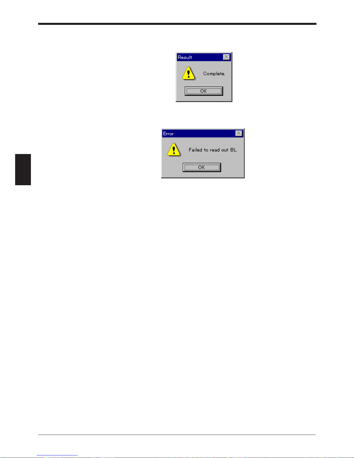
Chapter 4 Installing the Setup Software
76
4
4. If the settings of the BL-700 were successfully read, the following message
appears.
If the host computer failed to read the data, the following message appears.
If this message is displayed, check the following points:
• Check that [COM PORT] is set as shown in (1) when the 1st, 3rd and 5th
STABILITY LEDs from the top flash simultaneously (when in “setting data
send/receive waiting status”).
• Check that the power to the BL-700 is ON.
• Check that the RS-232C cable pin assignment of the BL-700 is the same as
that of the host computer.
Page 91
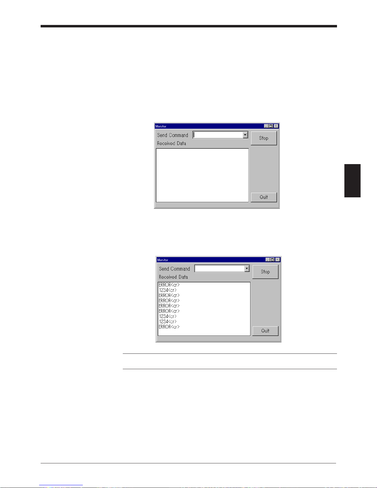
77
Chapter 4 Installing the Setup Software
4
4.5 Using Monitor
This setup software provides the “Monitor” program to check if the BL-700 can
send data properly. The “Monitor” program allows you to display the data read by
the BL series on the host computer’s monitor screen, and also to send a command
from the host computer to the BL-700 or BL series.
1. Click on [COM PORT] to set the communication parameters of the host com-
puter according to the current settings of the BL-700.
2. Click on [Monitor]. The MONITOR screen will appear.
3. When the BL series reads bar codes, the data read by the BL series is listed on
the screen (in the [Received Data] field). A record of up to 1000 lines of data
can be obtained. Using the scroll bar at the right of the [Received Data] field,
you can see the previous data.
Note: All commands should be entered in all uppercase characters. The BL cannot
accept lowercase characters.
Page 92
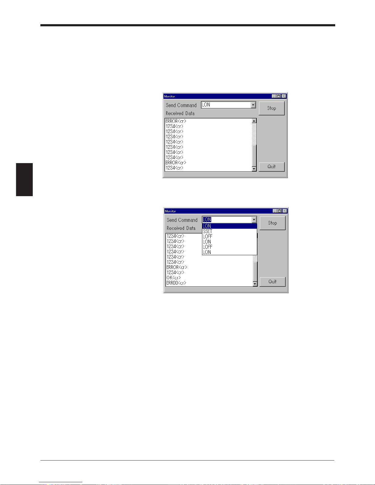
Chapter 4 Installing the Setup Software
78
4
4. If you click [Stop], received data is not listed. (The button name is changed to
[Start].) If you try to display received data again, click on [Start].
5. When you enter a command in the “Send command” field, you can send the
command to the BL-700 (or BL series). The format of the command to be sent
is “[Command] + [CR]”. Typing command and pressing [ENTER] key sends the
command.
6. When you click on the [ARROW] button in the “Send command” field, the
commands previously sent are listed. (Up to 100 commands can be listed.)
7. Click on [Quit] to quit this mode.
Page 93
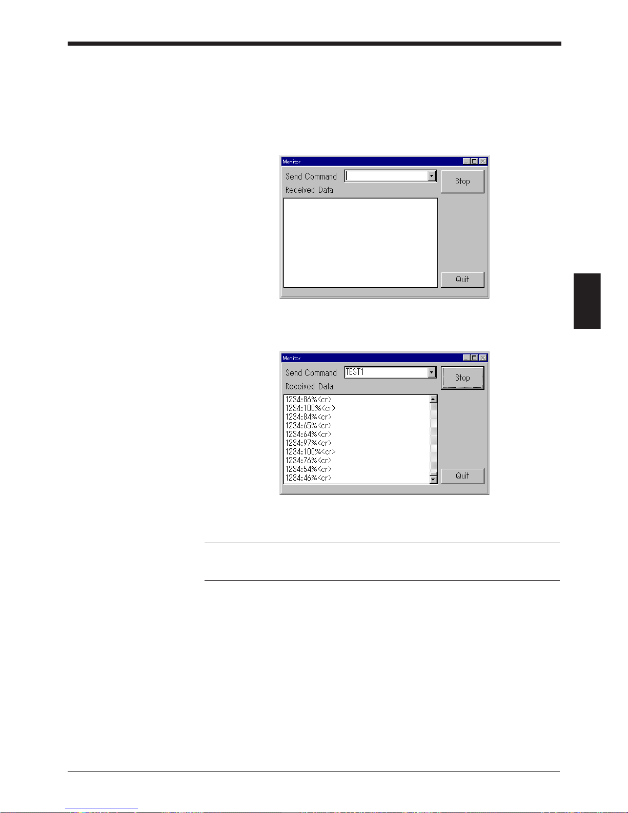
79
Chapter 4 Installing the Setup Software
4
Starting the test mode from the Monitor
Follow the procedure below to start the test mode from the Monitor.
1. Click [COM PORT] to match the computer’s communication protocol with the
current BL-700 communication protocol.
2. Click [Monitor] to display the monitor screen.
3. Enter “TEST1” (uppercase) in the send command column and press the [RE-
TURN] key. Readout rate measurement mode starts and the readout data is
listed sequentially.
4. To quit the test mode, enter “QUIT” in the send command column and press the
[RETURN] key.
Note: When you try to enter the test mode by turning on trigger input, you cannot
use the serial command to enter the test mode.
Commands should be entered in all uppercase characters.
Page 94
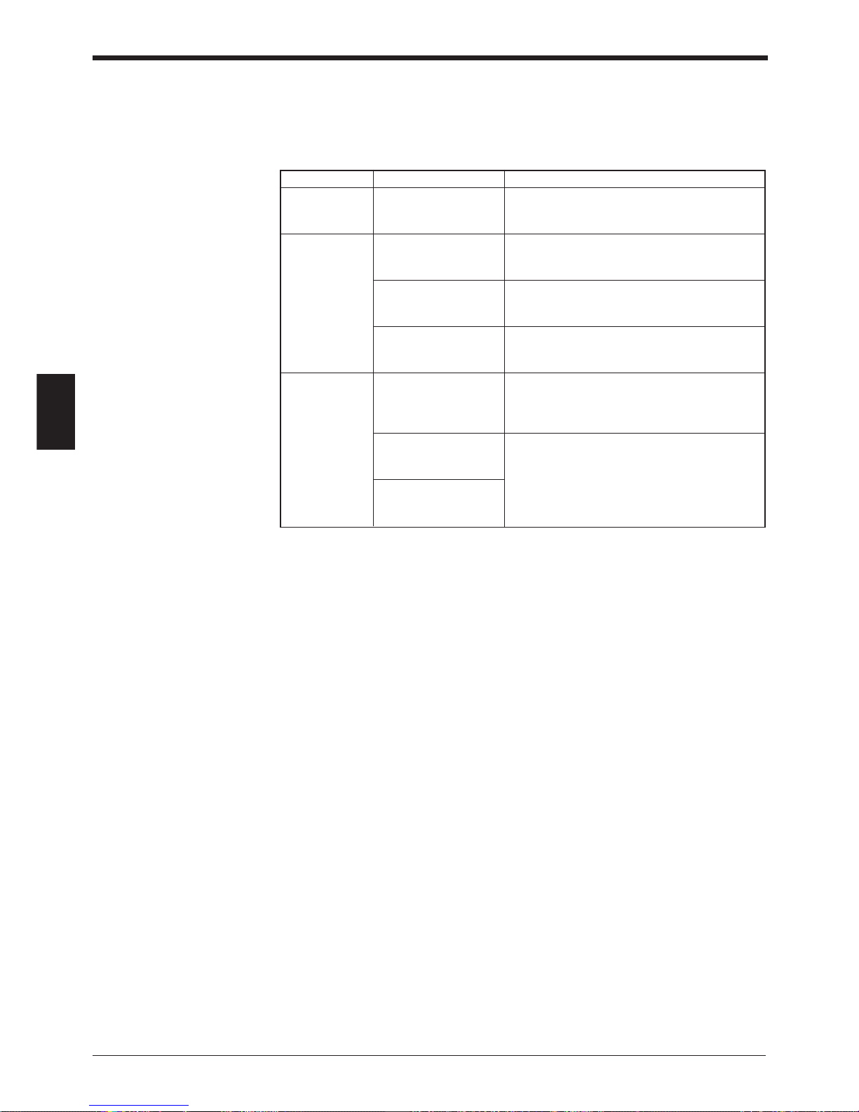
Chapter 4 Installing the Setup Software
80
4
4.6 List of Error Messages
The following table lists the error messages which may occur during operation of
the setup software.
Error message Contents
Errors during “Entered data is The entered data is incorrect. Re-enter the
setup incorrect. [OK]” correct data.
Errors during “Communication with Error during communication with the BL-700
communication BL-700 failed. [OK]” (for sending settings).
“Readout from BL-700 Error during communication with the BL-700
failed. [OK]” (for reading settings).
“The specified model is The model set in the setup software is not the
incorrect. [OK]” same as the model that is connected.
Errors file “Accessing file during No floppy disk is inserted.
editing rejected. [OK]” The floppy disk is write-protected.
The floppy disk is full.
“File not found. [OK]” The file name is incorrect. Enter a correct file
name.
“File name incorrect.
[OK]”
Page 95

81
Chapter 4 Installing the Setup Software
4
4.7 Example of printing from the setup software
When “Print” is executed from the setup software, the following data is printed.
/ / / New setting data [Untitled] / / /
< < Model = BL-700 > > [x] Selected
[_] ----------=> Changed
1) Main
[Read mode] [x] Single [_] Multi 1 [_] Multi 2 [_] Multi 3
[Data-send] [x] After read [_] At trigger input
[Repeat-reading time] [10] x 100 ms
[Decoding match count] [2] times
[Read error] ERROR [4552524F52]
[Add Decoding match count] [_] Enable
[Add scan count] [_] Enable
[Add code type] [_] Enable
[Add label orientation] [_] Enable
2) Trigger setup
[Signal type] [x] Level [_] One shot
[One shot input time] [10] x 100 ms
[Input time] [x] 2 ms [_] 10 ms
[State] [x] Nomally open [_] Nomally close
[Command for Trigger ON] LON [4C4F4E]
[Command for Trigger OFF] LOFF [4C4F4646]
[Test mode initiated with input ON] [x] OFF [_] Reading-rate check [_] Tact check
[Test mode initiated upon power-up] [x] OFF [_] Reading-rate check [_] Tact check
3) Comm Settings–1
[Baud rate] 9600 bps.
[Data bits] [x] 7 bits [_] 8 bits
[Parity] [x] Even [_] Odd [_] None
[Stop bits] [x] 1 bit [_] 2 bits
[RTS/CTS] [_] Use RTS/CTS handshaking
[Multi-drop link(RS-485)] [_] Enable
[ID number] No. [1]
4) Comm Settings–2
[Use PLC] [_] Enable
[Handshaking] [x] None [_] PASS/RTRY [_] ACK/NAK
[Header] [x] None [_] STX [_] ESC [_] Custom
[Delimiter] [x] CR [_] CR + LF [_] ETX [_] Custom
[Partition mark] : [3A]
[Intermediate delimiter] , [2C]
[Checksum] [_] Enable
5) Utility
[Stability LED] [_] Use stability LED
[OK/NG output duration] [50] x 10 ms
[Preset data] = [no data]
(1/2)
Page 96

Chapter 4 Installing the Setup Software
82
4
[Code 1 setup] Bar code = CODE39
[Main code length] [32]
[Min code length] [3]
[Send start/stop character (*)] [_] Enable
[Inspect check-digit [Modulus 43] [_] Enable
[Send check-digit] [x] Enable
-----Options setup-----[Max code length output] [x] Not used [_] Forward [_] Reverse
[Effective] [32]
[Starting] [1]
[Specify label orientation] [x] Not used [_] Forward [_] Reverse
[Code 2 setup] Bar code = Codabar
[Max code length] [32]
[Min code length] [3]
[Start/stop character] [_] Do not send [x] Lower-case [_] Upper-case
[Inspect check-digit] [_] Enable
[Send check-digit] [x] Enable
[Type of check-digit] Modulus 16
-----Options setup-----[Max code length output] [x] Not used [_] Forward [_] Reverse
[Effective] [32]
[Starting] [1]
[Specify label orientation] [x] Not used [_] Forward [_] Reverse
[Code 3 setup] Bar code = UPC/EAN
[Read EAN 13(UPC-A)] [x] Enable
[Read EAN 8] [x] Enable
[Read UPC-E] [x] Enable
[No. of UPC-A output] [x] 13 digits [x] 12 digits
[Add UPC-E system code 0] [x] Do not add [_] Add
-----Options setup----[Max code length output] [x] Not used [_] Forward [_] Reverse
[Effective] [32]
[Starting] [1]
[Specify label orientation] [x] Not used [_] Forward [_] Reverse
[Code 4 setup] Bar code = None
Printed: 98/01/07 20:40:28
(2/2)
Page 97

Chapter 5
Serial Communication
5.1 Serial Communication ........................................................ 84
5.2 Details on Data Communication ........................................ 85
5.3 Command Communication ................................................ 88
5.3.1 Setup of Direct Control Commands .......................................88
5.3.2 Details on Parameter Setting Commands ............................. 92
Page 98

Chapter 5 Serial Communication
84
5
5.1 Serial Communication
The BL-700 communicates with the PC via the RS-232C serial port. This enables
you to change the BL-700’s settings from your PC.
Communication types
The BL-700 provides the following two communication types:
• Data communication
Sends read bar code data from the BL-700 to the PC.
• Command communication
Changes the BL-700’s settings by sending a command from the PC to the BL-
700.
* All communication is performed using ASCII codes.
Communication setup
Configure the setup for BL-700 and the PC before attempting serial communication.
• Setup of BL-700
Set the following parameters for the BL-700 using the setup software.
• Baud rate, Data bits, Parity, Stop bit
• Communication protocol
• Header/Delimiter
• Read error code
• PC setup
Based on the BL-700’s settings, set the communication parameters on the PC
using the “Ports” setting in the Windows Control Panel/System/Device Manager.
• The following communication parameters are the default settings for the BL-700:
• Baud rate: 9600 bps
• Data bits: 7 bits
• Parity: Even
• Stop bit: 1 bit
Set the PC according to the above settings before attempting communication.
• The BL-700 is set, temporarily, to the default settings for 5 seconds after the power
switch is turned on.
When the current settings of BL-700 is not certain, send the command “SSET” and a
[CR] to the BL-700 from your PC with 5 seconds after power-up. This causes the BL700 to remain at its default settings and you can communicate with the BL-700 at the
default settings.
For information on checking the BL-700’s current settings, see “Details on Parameter
Setting Commands” on page 92.
For information on changing the above communication parameters see “Description of
Parameter Setting Commands” on page 94.
When the BL-700 TEST switch is pressed for 8 seconds, the 1st, 3rd and 5th STABILITY LEDs from the top flash, indicating that the communication parameters are set as
above. (Press the TEST switch again to reset the settings.)
Note: All commands should be entered in all uppercase characters. The BL cannot
accept lowercase characters.
Tips
Page 99
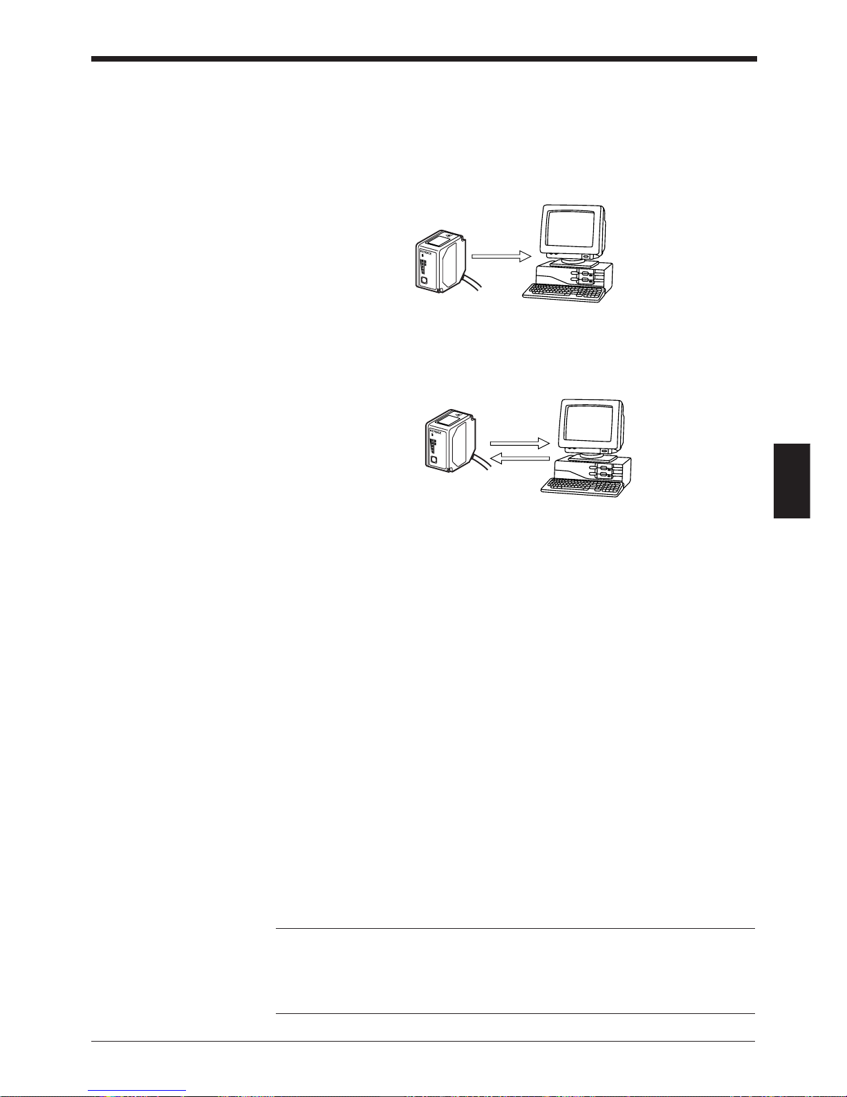
85
Chapter 5 Serial Communication
5
5.2 Details on Data Communication
Communication protocols (Hardware handshaking)
The BL-700 supports the following four handshaking protocols.
■ No Handshaking
• The BL-700 sends read data to the PC without using any handshaking protocol.
■ PASS/RTRY Handshaking
• After sending the read data, the BL-700 waits for a response from the PC. The
response is either a PASS command or a RTRY command.
The PASS command (quit) indicates that the PC has successfully received one
data packet. The BL-700 then prepares for the next data transmission.
• The RTRY command (request to re-send) indicates that the data was not
transmitted successfully. The command is a request to the BL-700 to re-send
the data. The BL-700 sends the same data again and then waits for the response.
After the BL-700 once receives PASS, the BL-700 sends back no data even if
RTRY is sent to the BL-700.
• The BL-700 can continue to read while waiting for the PASS command. The
data is stored in the BL-700’s transmission buffer.
➮
For the capacity of the transmission buffer, see P.86.
If the amount of stored data exceeds the capacity of the transmission buffer, the
BL-700 sends back [Header]OVER[Delimiter] to the PC, and clears all data
stored in the transmission buffer.
The BL-700 stops operation while clearing data. It recovers by sending PASS to
[Header]OVER[Delimiter].
• PASS and RTRY can be received in either communication format: PASS <CR>
or <STX> pass <ETX>. You can also add <ESC> to the beginning, or <LF> to
the end of the format.
Note 1: The BL-700 can receives other commands while waiting for the PASS
command. In this case, the BL-700 sends back an immediate response (e.g. OK).
Note 2: When the SSET command (
➮
see P.92
) is sent to the BL-700 while the
BL-700 is waiting for the PASS command, the BL-700 clears the data stored in the
transmission buffer, and enters the setting mode.
Read data
LASER
O
N
STB
OK/NG
TIM
IN
G
TE
ST
BL-700
(PASS, RTRY)
Read data
Response
LASER ON
STB
OK/NG
TIMING
TEST
BL-700
Page 100

Chapter 5 Serial Communication
86
5
■ ACK/NAK Handshaking
The ACK/NAK handshaking uses <ACK> (06H) and <NAK> (15H) instead of PASS
and RTRY used in the PASS/RTRY handshaking, respectively. With these protocols, the BL-700 sends back different characters, but performs the same operation.
■ RTS/CTS Handshaking
• When the PC’s RTS (BL-700’s CTS) signal turns off, the BL-700 becomes
ready for data transmission. When the PC’s RTS signal turns on, the BL-700
starts data transmission.
• When the PC’s RTS signal is off, the BL-700 can still read. In this case, data is
stored in the BL-700’s transmission buffer (see below).
If the amount of stored data exceeds the capacity of the transmission buffer, the
BL-700 sends back [Header]OVER[Delimiter] to the PC, and clears all data
stored in the transmission buffer.
The BL-700 stops operation while clearing data. It recovers when the RTS of
the computer turns ON.
Note 1: The RTS/CTS handshaking cannot be used for RS-422A communication.
Note 2: The RTS/CTS protocol can be used together with other handshaking
protocols.
Note 3: When the PC’s RTS signal is off, the BL-700 does not sends back a
response to the PC.
Capacity of transmission buffer
The BL-700’ s transmission buffer can store 400 bytes (400 characters).
The number of characters stored in the transmission buffer for each data packet is
the number of characters in the data (including additional data such as the number
of decoding match count) plus an additional five characters indicating the data’s
attributes.
When multi label reading mode 2 or 3 is used, these five attribute characters are
added to each data packet.
Example 1
When the number of bar code digits is 10 (with no additional data)
400 ÷ (10 + 5) = 26
The transmission buffer can store 26 pieces of data.
Example 2
When the number of bar code digits is 20 (with no additional data)
400 ÷ (20 + 5) = 16
The transmission buffer can store 16 pieces of data.
 Loading...