

Page 1
ASSEMBLY INSTRUCTIONS
DALLAS FENCE
ITEM : 000001 VER : 0 USA
IMPORTANT: You must read these instructions carefully before you start to assemble this fence. Please carry out the steps in the order set out in these instructions.Keep these instructions
in a safe place for future reference.
GENERAL INFORMATION: The Keter Fence is easy to install. We incorporate methods and procedures used by professional installers to guide you through to the successful
completion of your fence.
GENERAL ADVICE: This is a 2 person assembly job.If it is a property line fence, you will want to confirm your property lines
before ordering your fence.The component parts should be checked and laid out in an orderly way, close at hand.Keep all small parts
(screws, etc.) in a bowl so that they do not get lost.
Please keep the tracking number which appears on the box, and refer to this number when calling the service office for questions or complaints.
CARE & MAINTENANCE :When your fence needs a clean, use a mild detergent solution and rinse with cold clean water.
DO NOT use acetone, abrasive cleaners or other special detergents to clean the fence.
For general support and replacement parts, please contact :
U.S: Call Toll Free:1-(888)-374-4262 , fax 317-575-4502, 11495 North Pennsylvania ST., Suite 110 Carmel, Indiana, 46032, U.S.A
Canada: Tel: 514-7486-721 , Fax: 514-7487-793 , E-mail: jessicaz@accenthome.com
United Kindom: Keter (UK) Ltd. Unit 4, Woodgate Business Park, Clapgate Lane, Birmingham, B32 3DB, United Kindom. Tel: 0121-5060008, Fax: 0121-4220808
The Netherlands: Keter Benelux, Ericssonstraat 17, Postbus 224, 5120 AE Rijen, The Netherlands. Tel: 31-1612-28301, Fax: 31-1612-28322
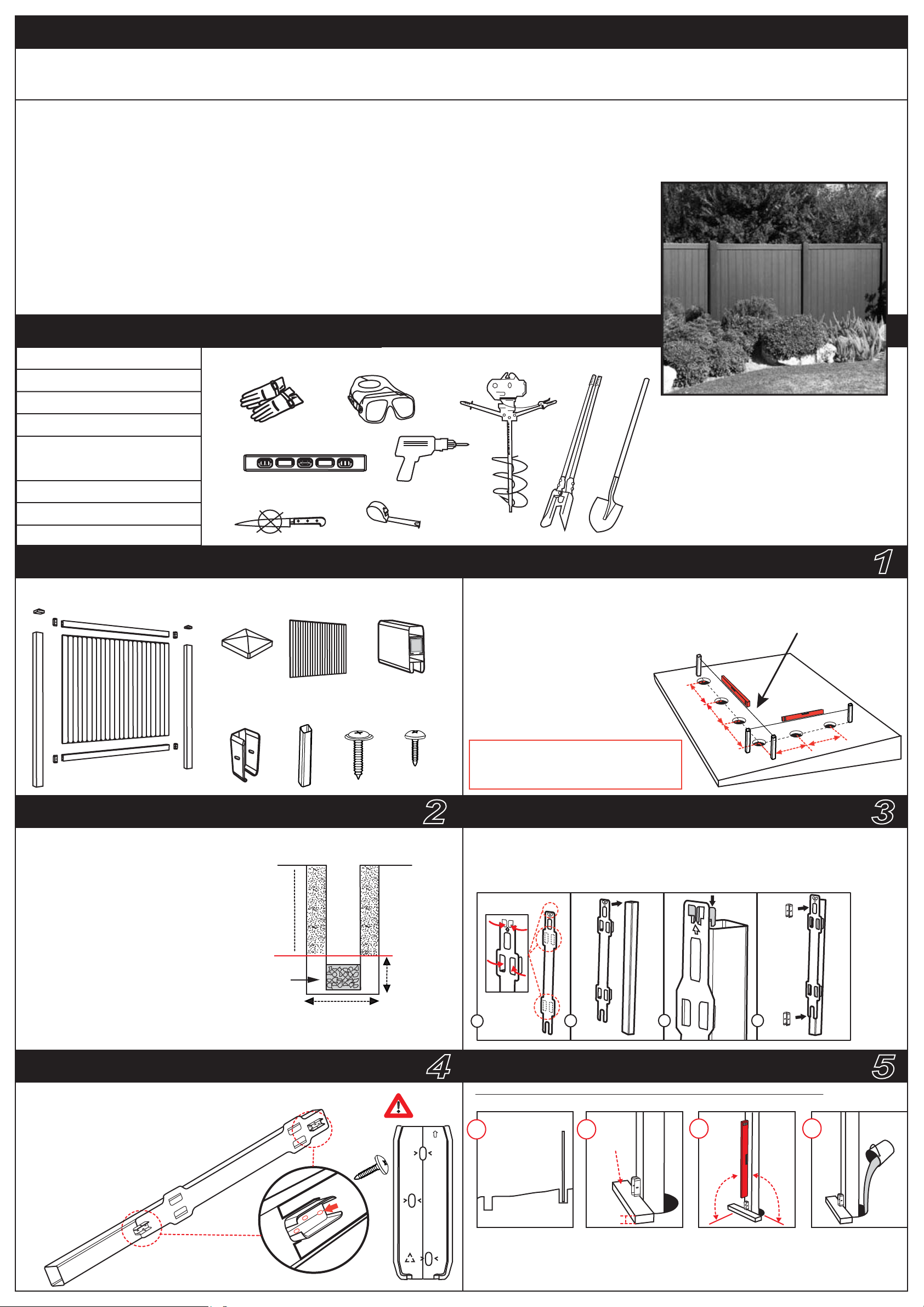
TOOLS & MATERIALS
string line
post hole digger / power auger
A-13-00 544993
mallet
work shoes
4 timber stakes
2”x 2”x24” (5cm x 5cm x 60cm)
concrete / dry mix
PARTS & DIMENSION
POST
CAP x2
BRACKET
x4
fcb
u
PANEL
x1
POST
x 2
SC35B x8
(1.4”)
RAILS
x 2
SC15 x12
(0.6”)
PROJECT PLANNING
1. Stake out fence from beginning to end.
.2. Estimate the ground level.
3. Start at the highest side of the fence line !
4. Dig hole under post line. make sure the
distance between holes centers is 6’ (183cm).
For fence sections that are less than the standard
6’ (183 cm) center-to-center, simply cut to size the
rails and the fence panels, using a power saw
(use metal fit blade).
.
183cm
6’
183cm
6’
183cm
6’
www.keter.co.il
String fence line to show
horizontal accuracy
6’
183cm
6’
183cm
1
GENERAL ADVICE ON POST HOLES POSITIONING GUIDE
Using post hole digger or power auger
or simple shovel dig the hole 12” (30cm)
in diameter. Main and gate posts should
be 6” (15cm) deeper for extra strength.
Backfill each hole with 6” of gravel to drain
water away.
(24”) 65cm hole depth
Gravel to reduce
frost HEAVE
Hole diameter (12”) 30cm
BRACKETS ASSEMBLY FIXING FIRST POST
1.
Attach two rail bracketsTS to One side of the posts
using the positioning guide.
2.Do not assemble brackets on both sides
of the post !
3.Locate all bracket screws on center
of elongated holes on bracket for
expansion and contraction.
The lip of the bracket
should be on the
bottom.
POST
TOP
X3
up
2
(6”) 15cm
below frost line
4
Top of
bracket
fcb
up
1. Use the positioning guide to place the brackets .
A. fold the positioning guide wings.
B. Attach the positioning guide to the post as shown.
C. Place the bracket within the positioning guide holes.
A
Place first post in the hole, checking that it satisfies ALL the following conditions:
START AT THE HIGHEST
GROUND POINT
A
GROUND
A. Position the first post at the highest ground point of the fence line !
B. Place 2’’ (5cm) timber, under the bracket to maintain the gap between the fence and the ground.
C. Check for VERTICAL in two directions.
D. Fill the hole with concrete leaving a slope for water drainage.
E. Allow concrete to set for 10-15 minutes
B
HEIGHT
B
TIMBER
2”
C D
VERTICAL
C
builder's
level.
o
90
3
5
ADD CONCRETE
D
o
90
Page 2
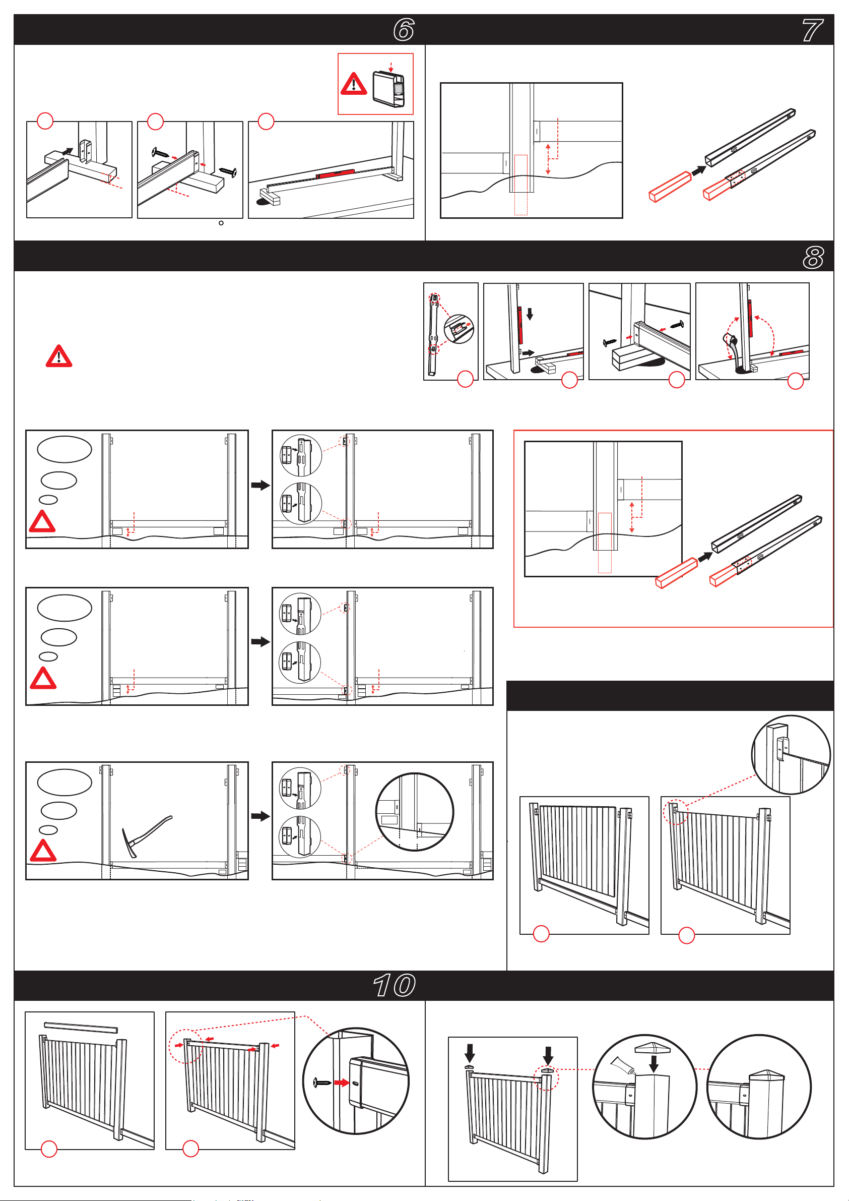
FIXING FIRST RAIL
6
EXTENDING THE POST
7
1. Place the lower rail in position.
2. Fix the rail to the post with 2 screws (SC35B), through the
bracket holes.
3. level the rail horizontely use a timber to support.
1
2”
(5cm)
2
2” (5cm)
3
This side up
The post must be at least 12” In ground if you have a slope that is over 12” you
must extend the post with timber as showen.
(30cm-50cm)
GROUND
Make sure the rail is leveled horizontly &90 to the second post
FIXING NEXT POST (Take into account level, downward and upward slopes)
1. Attach two brackets to the post using the positioning guide.
2. place the post in the hole
3. Fix the post to the rail with 2 screws (SC35B) , through the bracket holes.
4. Add Concrete use dry or mix concrete. Allow concrete to set for 10-15 minutes.
up
12”-20”
(use 4”/4”/24”,10cm/10cm/65cm timber 8 screw)
8
90
o
90
o
Verify that rail is leveled and post is vertical on both direction !
1
Position the brackets on the empty side (In continuation direction) of the post considering the 3 following
options: folow
option 1
Level
2nd post
2”-6” (5cm-15cm)
?
GROUND
2” -6” (5cm-15cm) place the positioning guide from top of the post & fix the brakets 3 screw (sc15) for each.
2nd post
2”-6” (5cm-15cm)
GROUND
option 2
Downward slope
2nd post
6”-12” (5cm-15cm)
2nd post
6”-12” (5cm-15cm)
2
12”-20”
(30cm-50cm)
If the distance is more then 12” you must extend the post
3
4
?
GROUND
6” (15cm) And up, place the lower bracket 2” (5cm) from ground use positioning guide for the second
bracket.
GROUND
option 3
Upward slope
3th post
?
GROUND
In the case of upward slope, connect the brackets 2” (5cm) up and/or position the new post
lower while digging a trench for the rail .
Make sure (using the positioning guide) that upper bracket on the left side is not out of the post top.
2nd post
GROUND
3th post
GROUND
INSTALLING FENCE SECTION
2nd post
1
1. Assemble the first panel into
the bottom rail.
2
2. Make sure the panel goes into
the brackets.
9
INSTALLING FENCE SECTION
1
Assemble the upper rail on
top of the panel.
2
Use two screws to fix the rail
to the bracket
10
X2
SCREW FROM
BOTH SIDES
ATTACH POST CAPS.
1.Press caps down on post top.
2. you can secure the caps with super glue
11
PP GLUE
Page 3

INSTRUCCIONES DE ENSAMBLADO
DALLAS 6x6
IMPORTANTE: debe leer estas instrucciones con atención antes de intentar armar esta cerca.
Siga estos pasos en el orden que se indica en las instrucciones, las cuales deberá guardar en un lugar seguro, para su futura referencia.
INFORMACIÓN GENERAL: la cerca KETER es fácil de instalar. Incorporamos métodos y procedimientos
empleados por instaladores profesionales para guiarlo mientras completa correctamente el armado de su cerca.
CONSEJOS GENERALES: esta tarea de armado requiere la intervención de 2 personas.
Si se trata de una cerca para delimitar una propiedad, le conviene confirmar cuáles son los límites de la misma antes de pedir su cerca.
Las partes componentes deben ser verificadas y tendidas en forma ordenada y debe tenerlas a mano.
Mantenga todas las partes pequeñas (tornillos etc.) en un recipiente, para no perderlos.
Conserve el número de guía [tracking number] que aparece en la caja y remítase a este número cuando llame a la oficina de servicio para hacer preguntas o reclamos.
CUIDADOS Y MANTENIMIENTO: cuando tenga que limpiar su cerca, utilice una solución detergente suave y enjuáguela con agua limpia y fría.
NO use acetona, limpiadores abrasivos u otros detergentes especiales para limpiar la puerta.
Para solicitar soporte en general y partes de reemplazo, comuníquese con el centro de atención al cliente de Accent Home Products:
EE. UU.: 1-888-374-4262
Canadá: 1-800-661-6721
Reino Unido:
Cordel
Taladro perforador / taladro de
tierra mecánico
0121-5060008
South America: Tel. +541145820777 / Fax +541154820188
Otros países europeos: 31-1612-28301
www.keter.com
HERRAMIENTAS Y MATERIALES
562625 A-1342 ES
Maza
Calzado de seguridad
4 maderos
2”x 2”x 24” (5 cm x 5 cm x 60 cm)
Cemento/mezcla seca
PARTES Y DIMENSIÓN
KIT DEL PANEL
PANEL
(x1)
BARANDAS
E INFERIOR/
SUPERIOR
(x2)
POSTE
(x1)
MÉNSULA
(x4)
fcb
u
KIT DEL POSTE
s35 (x8)
20 mm
TAPA DEL
POSTE (x1)
s18b (x12)
15mm
PLANTILLA
(x1)
PLANIFICACIÓN DEL PROYECTO
1. Delimite la cerca del principio al fin.
2. Calcule el nivel del suelo.
3. Comience por el lateral más elevado de la
línea de la cerca.
4. Cave un pozo debajo de la línea del poste.
Asegúrese de que la distancia entre
los centros de los agujeros
sea de 6’ (1,82 m).
Para aquellas secciones de la cerca que
sean más pequeñas que lo convencional,
es decir, menores a 6’ (182 cm) de centro
a centro, simplemente corte las barandas
y la cerca al tamaño adecuado, con una
sierra eléctrica (utilice una hoja metálica).
(1,82 m)
6’
(1,82 m)
6’
(1,82 m)
6’
1
Cordel / línea de la cerca
para demostrar la
precisión horizontal
6’ (1,82 m)
6’ (1,82 m)
RECOMENDACIONES GENERALES SOBRE
LOS POZOS PARA LOS POSTES
Con un taladro perforador, un taladro de tierra mecánico o una pala, cave un pozo de
12” (30 cm) de diámetro y 30” (75 cm) de
profundidad. Agregue 6” (15 cm) de grava
para el drenaje del pozo. Inserte el poste en el
centro del mismo. Nivele el poste y comprímalo
con firmeza dentro del pozo. Llene lo que resta
del pozo con cemento, de acuerdo con las
instrucciones de fábrica.
Profundidad del
pozo 24” (60 cm)
Grava para reducir los
DAÑOS por heladas
Diámetro del pozo
12” (30 cm)
MONTAJE DE LAS MÉNSULAS FIJACIÓN DEL PRIMER POSTE
1. Coloque las dos ménsulas de las barandas (fcb) en un lado de los postes.
2. No coloque las ménsulas en ambos lados del poste.
3. Coloque la guía de posicionamiento a 68” (172 cm)
de la parte superior del poste y luego coloque la ménsula.
4. Sitúe todos los tornillos s18b de las ménsulas
en el centro de los orificios alargados
de la ménsula, para la expansión y contracción.
El reborde de la ménsula debe estar
en la base.
68" (172 cm)
POST
TOP
X3
up
2
6” (15 cm)
debajo de la
línea de la
helada
4
Parte superior
de la ménsula
fcb
up
GUÍA DE POSICIONAMIENTO
A. Doble las aletas de la guía de posicionamiento (plantilla).
B. La guía de posicionamiento debe colocarse a 68” (172 cm) de la parte
superior del poste.
C. Coloque la guía de posicionamiento en el poste, tal como se muestra.
D. Coloque la ménsula dentro del agujero de la guía de posicionamiento.
A
Coloque el primer poste en el pozo, constatando que satisfaga TODAS las condiciones
mencionadas a continuación:
Punto más alto del suelo
A
SUELO
B
B
MADERO
2”
(5 cm)
ALTURA
C D
VERTICAL
C
Nivel
o
90
o
90
AGREGAR CEMENTO
D
3
5
A. Ubique el primer poste en el punto más alto del suelo de la línea de la cerca.
B. Coloque los maderos de 5 cm debajo de la ménsula; mantenga la separación entre la cerca y el suelo.
C. Revise la VERTICALIDAD en ambas direcciones.
D. Utilice cemento o mezcla seca y DÉJELO SECAR durante 10 minutos.
Page 4

FIJACIÓN DE LA PRIMERA BARANDA
6
EXTENSIÓN DEL POSTE
7
1. Coloque la baranda inferior en su posición.
2. Fije la baranda al poste con 2 tornillos s35, a través de los orificios de
la ménsula.
3. Nivele la baranda horizontalmente, utilizando un madero como ayuda.
1
2”
(5 cm)
Asegúrese de que la baranda esté nivelada horizontalmente a 90º respecto del segundo poste.
2
2”
(5 cm)
3
Este lado hacia arriba
El poste debe colocarse al menos a 12“ (30 cm) en el suelo. Si usted tiene una pendiente
mayor de 12“ (30 cm) debe extender el poste con el madero tal como se muestra.
Utilice un madero de 4”/4”/24” (11/11/60 cm)
Fije con el tornillo 8.
12”-20“ (
30-50 cm)
SUELO
FIJACIÓN DEL SEGUNDO POSTE (tenga en cuenta el nivel y la pendiente ascendente y descendente)
1. Coloque las dos ménsulas en el poste, usando la guía de posicionamiento.
2. Ubique el poste en el pozo.
3. Fíjelo a la baranda, con 2 tornillos (s35), a través de los agujeros de la ménsula.
4. Agregue cemento o mezcla seca. Espere unos 10-15 minutos hasta que el
cemento se endurezca.
Verifique que la baranda esté nivelada y que el poste
esté vertical en ambas direcciones.
up
1
2
3
90
o
90
8
o
4
NIVEL, PENDIENTE DESCENDENTE Y PENDIENTE ASCENDENTE
Ubique las ménsulas del lado vacío (en la dirección de continuación) del poste, considerando las siguientes 3 opciones:
Opción 1
2.º poste
2”-6” (5 cm-15 cm)
?
Si es de 5-15 cm coloque la guía de posicionamiento a 10 cm del suelo y fije las ménsulas
con 3 tornillos (s18b) para cada una.
Opción 2
2.º poste
2”-6” (5 cm-15 cm)
?
Nivel
SUELO
Pendiente
descendente
1.º poste
1.º poste
2.º poste
2”-6” (5 cm-15 cm)
SUELO
2.º poste
2”-6” (5 cm-15 cm)
1.º poste
1.º poste
Opción 3
Pendiente
ascendente
3.º poste
?
SUELO SUELO
En caso de una pendiente ascendente, conecte las ménsulas a 2” (5 cm) arriba y/o
ubique el nuevo poste más abajo, mientras cava una zanja para la baranda.
Asegúrese (usando la guía de posicionamiento) de que la ménsula superior del lado
izquierdo no quede fuera de la partes superior del poste.
2.º poste
3.º poste
SUELO
9
2.º poste
SUELO
Si la distancia es mayor que 6” (15 cm) coloque la ménsula inferior a 2” (5 cm) del suelo
y utilice 3 tornillos (s18b). Fije la segunda ménsula usando la guía de posicionamiento. Utilice 3 tornillos (s18b).
SUELO
INSTALACIÓN DE LA SECCIÓN DE LA CERCA
1
Ensamble el panel
en la baranda inferior.
2
Asegúrese de que el panel
entre en las ménsulas.
3
Coloque la baranda superior
sobre el panel.
4
Utilizando los tornillos (s35),
fije las baranda superior a las ménsulas.
COLOCACIÓN DE LAS TAPAS DE LOS POSTES
10
(x2)
ATORNILLE DESDE
AMBOS LADOS
11
1. Presione las tapas hacia abajo,
sobre la parte superior del poste.
2. Puede fijar las tapas con silicio.
silcion
Para las secciones de la cerca con una
medida inferior a la estándar,
que es de 6’ (182 cm) de centro a centro,
simple - mente corte las barandas al tamaño
y los paneles de la cerca,
con una sierra eléctrica.
 Loading...