

Page 1

System s30
Installation and Servicing Instructions
FAN POWERED HIGH EFFICIENCY
MODULATING DOMESTIC CONDENSING
GAS SYSTEM BOILER
When replacing any part on this appliance, use only spare parts that you can be
assured conform to the safety and performance specication that we require.
Do not use reconditioned or copy parts that have not been clearly authorised by Keston.
For the very latest copy of literature for specication and maintenance practices visit our website
www.keston.co.uk where you can download the relevant information in PDF format.
October 2017
UIN 215352 A05
Page 2

ERP DATA
SYMBOL UNITS 30
Condensing Boiler n/a n/a yes
Low Temperature Boiler n/a n/a no
B1 Boiler n/a n/a no
Cogeneration Space Heater n/a n/a no
Equipped with a Supplementary Heater n/a n/a no
Combination Heater n/a n/a no
Nominal Heat Output for Space Heating
Full Load P
Part Load P
Auxiliary Electricity Consumption
Full Load el
Part Load el
Standby P
Seasonal Space Heating Energy Efciency
Full Load
Part Load
Standby Loss P
Ignition P
4 kW 30.3
1 kW 9.9
max kW 0.048
min kW 0.013
SB kW 0.005
ƞ
4
ƞ
1
stby kW 0.055
ign kW 0
MODEL
% 89.8
% 98.2
Emissions NO
Annual Energy Consumption Q
Sound Power Level, Indoors L
x mg/kWh 29
HE GJ 93
WA dB 48
2
Installation and Servicing
Page 3
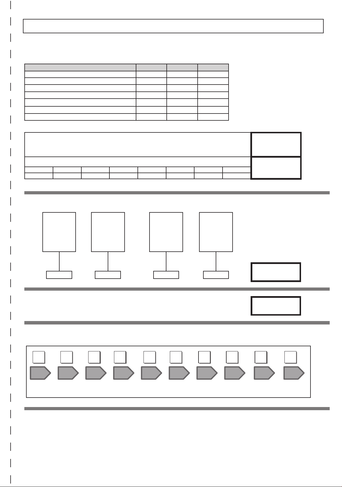
PRODUCT FICHE
KESTON SYSTEM S BOILER
Keston Heating
ERP DATA
SYMBOL UNITS MODEL
30
Condensing boiler Yes
Seasonal Space heating efciency class A
Rated heat output kW 30
Seasonal space heating energy efciency
Annual energy consumption Q
Sound power level, indoors L
Seasonal Space Heating Energy Efciency of the Boiler *%
Temperature control (from che of temperature control) %
Class I Class II Class III Class IV Class V Class VI Class VII Class VIII
1% 2% 1.5% 2% 3% 4% 3.5% 5%
ƞs
HE GJ 93
WA dB 48
% 93*
A
B
Solar Contribution (from che of solar device)
Collector Size
(in m2)
= (‘III ’x + ‘IV ’ x ) x 0.9 x ( / 100 x =
Seasonal Space Heating Energy Efciency of Package
Seasonal Space Heating Energy Efciency Class of Package
Tank Volume
(in m3)
Collector
Efciency
(in %)
Tank rating
A* = 0.95
A = 0.91
B = 0.86
C = 0.83
D-G = 0.81
TOTAL: A+B+C=
%
C
%
GG F E D C B A A+ A++
< 30% ≥ 30% ≥ 34% ≥ 36% ≥ 75% ≥ 82% ≥ 90% ≥ 98% ≥ 125% ≥ 150%
The energy efciency of the package of products provided for in this document may not correspond to its actual energy efciency once installed in a
building, as the efciency is inuenced by further factors such as heat loss in the products in relation to the building size and its characteristics
Installation and Servicing
A+++
3
Page 4

4
Installation and Servicing
Page 5

NOTES FOR THE INSTALLER
FOR ANY TECHNICAL QUERIES PLEASE RING THE KESTON
INSTALLER/TECHNICAL HELPLINE : 01482 443005
NOTE. BOILER RESTART PROCEDURE -
To restart the boiler press the RESTART button. The boiler will repeat the ignition sequence if a heat
demand is present.
DOCUMENT AMENDMENTS
Relevant Installation changes implemented in this book from Mod Level ......... A04 (Jun 17) to A05 (Oct 17)
Page 11 - Section 1.7 - Location of Boiler
Compartment Installation - new para added regarding Braces.
Page 12 - Section 1.8 - Gas Supply
New para added checks to gas valve connections.
Page 24 - Section 2.10 - Assembly Practice
New Important note added after “Installing Flue and Air Pipes”.
Page 57 - Spare Parts
Note added ref to Propane Boiler.
USER GUIDE
Front Page
Addition of UIN, Mod Level & Date
Installation and Servicing
Keston reserve the right to vary specication without notice
5
Page 6

6
Installation and Servicing
Page 7

CONTENTS
1 GENERAL .................................................................... 8
1.1 Introduction ................................................................10
1.2 Operation ...................................................................10
1.3 Safe Handling ............................................................. 10
1.4 Optional Extra Kits .....................................................10
1.5 Safety ......................................................................... 11
1.6 Safe Handling of Substances ..................................... 11
1.7 Location of Boiler ...................................................... 11
1.8 Gas Supply ................................................................. 12
1.9 Water Circulation System ........................................... 12
1.10 Boiler Control Interlocks .............................................12
1.11 Electrical Supply ......................................................... 12
1.12 Condensate Drain .................................................... 12
1.13 Boiler Dimensions, Services & Clearances ................ 13
1.14 System Requirements ................................................ 14
1.15 System Balancing ......................................................15
1.16 Water Treatment......................................................... 15
1.17 Boiler Assembly - Exploded View ...............................16
1.18 Unpacking .................................................................. 17
1.19 Front Panel Removal .................................................17
2 INSTALLATION .........................................................18
2.1 Flue System ............................................................... 18
2.2 Flue Installation Example Keston System S 30 .........20
2.3 Flue Installation Example Keston System S 30 .........20
2.4 Flue Termination Position ........................................... 21
2.5 Installing The Boiler .................................................... 22
2.6 Wall Mounting Template ............................................. 22
2.7 Preparing The Wall .....................................................22
2.8 Fitting The Wall Mounting Plate ................................. 23
2.9 Mounting The Boiler ................................................... 23
2.10 Assembly Practice ...................................................... 24
2.11 Fitting The Sleeving ...................................................25
2.12 Condensate Drain ...................................................... 26
2.13 Connections & Filling .................................................28
2.14 Electrical Connections ................................................ 29
2.15 Installer Wiring ...........................................................29
2.16 Replacing Pre-Fitted Mains Cable .............................31
2.17 Fitting The Weather Compensation Kit ...................... 31
2.18 External Electrical Controls ........................................ 32
2.19 Fitting The Weather Compensation Kit ..................... 32
2.20 Wiring Diagram ..........................................................33
2.21 Commissioning And Testing ....................................... 34
2.22 Initial Lighting ............................................................. 35
2.23 General Checks .........................................................36
2.24 Restart Procedure ...................................................... 36
2.25 Accessing The Installer Mode .................................... 37
2.26 Handing Over ............................................................. 37
3 SERVICING
3.1 Servicing Schedule ....................................................38
3.2 Boiler Front Panel Removal / Replacement ............... 39
3.3 Fan and Venturi Assembly Removal and Cleaning .... 39
3.4 Burner Removal and Cleaning ................................... 40
3.5 Cleaning the Condensate Trap/Siphon ...................... 40
3.6 Cleaning the Heat Exchanger .................................... 41
3.7 Reassembly ...............................................................41
3.8 Replacement of Components ..................................... 42
3.9 Fan Replacement ....................................................... 42
3.10 Burner Injector Replacement .....................................43
3.11 Burner Replacement .................................................. 43
3.12 Return Thermistor Replacement ............................... 44
3.13 Ignition Electrode Replacement ................................. 44
3.14 Flame Detection Electrode Replacement ................... 45
3.15 Spark Generator Replacement ..................................45
3.16 Gas Control Valve Replacement ................................ 46
3.17 Condensate Trap / Siphon Replacement ................... 46
3.18 PCB Replacement ...................................................... 47
3.19 Draining the Boiler ...................................................... 47
3.20 Pressure Gauge Replacement ................................... 48
3.21 Safety Relief Valve Replacement ............................... 48
3.22 Pump Automatic Air Vent Replacement .....................48
3.23 Pump Head Replacement .......................................... 49
3.24 CH Water Pressure Switch Replacement .................. 49
3.25 Control / No Flow Thermistor Replacement ............... 49
3.26 Heat Engine Replacement ......................................... 50
3.27 Expansion Vessel Recharging & Replacement .......... 51
4 FAULT FINDING ........................................................ 52
4.1 Fault Finding Chart Main Menu .................................. 52
‘L1’-Flow Temp Ov’heat Lockout/No Water Flow Lockout
4.2
4.3 ‘L2’ - Ignition Lockout ................................................. 53
4.4 ‘L6’ - False Flame Lockout ........................................ 54
4.5 ‘F1’ - Low Water Pressure .......................................... 54
4.6 ‘F2’ or ‘Fn’ or ‘Ln’ - Flame Loss ..................................54
4.7 ‘F3’ - Fan Fault ........................................................... 54
4.8 ‘L4’ or ‘F4’ - Control / No Flow Thermistor Fault ......... 55
4.9 ‘F5 or L5’ - Return Thermistor Fault ........................... 55
4.10 ‘F6’ - Outside Sensor Fault.........................................55
4.11 No CH Operation ........................................................ 56
4.12 No Display .................................................................. 56
4.13 No HW ........................................................................ 56
5 SPARE PARTS .......................................................... 57
6 BENCHMARK & COMMISSIONING ......................... 58
... 53
Installation and Servicing
7
Page 8
SECTION 1 - GENERAL
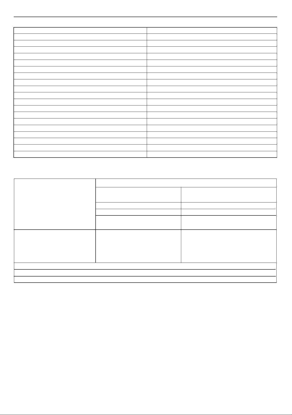
Table 1 - General Data
30
Gas supply 2H - G20 - 20mbar
Gas Supply Connection 15mm copper compression
Injector Size (mm) 4.65
Flow Connection Central Heating 22mm copper compression
Return Connection Central Heating 22mm copper compression
Flue Terminal Diameter mm (in) 50 (2)
Average Flue Temp-Mass Flow Rate 69
CO
Content (± 0.7) Max. CH 9.3 %
2
Min. CH 8.8 %
Maximum Working Pressure (Sealed Systems) bar (lb/in
2
) 2.5 (36.3)
Electrical Supply 230 V ~ 50 Hz.
Power Consumption W 100
Fuse Rating External : 3A Internal : T4A HRC L250 V
Water content litre (gal) 1.2 (0.26)
Packaged Weight kg 31.6
Maximum Installation Weight kg 26.2
Boiler Casing Size Height mm 700
Width mm 395
Depth mm 278
o
C - 13g/s
Table 2 - Performance Data - Central Heating
30
MIN MAX
Boiler Input :
Boiler Input ‘Q’ Nett CV kW 6.1 30.4
Gross CV kW 6.7 33.7
3
Gas Consumption m
(ft
/h 0.622 3.135
3
/h) (22) (111)
Boiler Output :
Non Condensing kW 6.1 30.3
o
C Mean Water temp.
70
Condensing kW 6.4 31.0
o
C Mean Water temp.
40
Seasonal efciency* SEDBUK 2005 91.1%
Seasonal efciency* SEDBUK 2009 89.6%
NOx Classication CLASS 5
* The value is used in the UK Government’s Standard Assessment Procedure (SAP) for energy rating of dwellings. The test data from
which it has been calculated have been certied by a notied body.
Note. Gas consumption is calculated using a
caloric value of 38.7 MJ/m
3
(1038 Btu/ft3) gross or
34.9 MJ/m3 (935 Btu/ft3) nett
To obtain the gas consumption at a different caloric
value:
a. For l/s - divide the gross heat input (kW) by the
gross C.V. of the gas (MJ/m
3
)
b. For Btu/h - multiply the gross heat input (kW) by
26.8
3
c. For ft
/h - divide the gross heat input (Btu/h) by
Key to symbols
GB = United Kingdom IE = Ireland (Countries of destination)
PMS = Maximum operating pressure of water
C
= A room sealed appliance designed for connection via ducts to a horizontal
13 C53
terminal, which admits fresh air to the burner and discharges the products
of combustion to the outside. The fan is up stream of the combustion
chamber.
I
= An appliance designed for use on 2nd Family gas, Group H only.
2H
the gross C.V. of the gas (Btu/ft3)
3
d. For m
/h - multiply l/s by 3.6
8
Installation and Servicing
Page 9
SECTION 1 - GENERAL
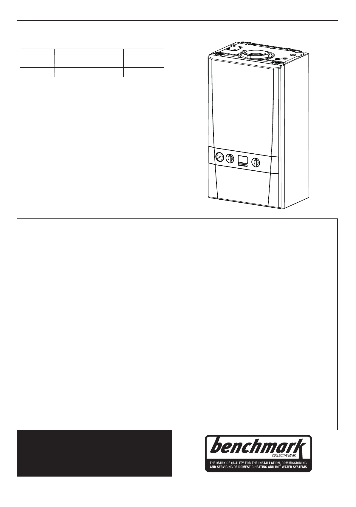
Keston System S
Natural Gas only
Boiler size G.C. Appliance No. PI No.
(Benchmark No.)
30 41-930-45 86 CR 18
Destination Country: GB, IE
For GB, to comply with Building Regulations Part L1 (Part 6 in Scotland) the boiler should be tted in accordance with the
manufacturer’s instructions. Self-certication that the boiler has been installed to comply with Building Regulations can be
demonstrated by completing and signing the Benchmark Commissioning Checklist.
Before installing this boiler, read the Code of Practice sheet at the rear of this book.
BENCHMARK COMMISSIONING CHECKLIST DETAILS
Boiler Page
Make and model ......................................................... 9
Appliance serial no. on data badge .......... Front Cover
SEDBUK No. % .......................................................... 8
Controls
Time and temperature control to heating .................32
Time and temperature control to hot water ........... N/A
Heating zone valves ................................................. 32
TRV’s........................................................................ 12
Auto bypass ............................................................. 12
Boiler interlock .......................................................... 12
For .................................................................... all boilers
Flushing to BS.7593 ................................................. 15
Inhibitor ....................................................................15
Central heating mode
Heat input ...................................................to be calculated
Page
Burner operating pressure ...................................... n/a
Central heating ow temp. ...........measure and record
Central heating return temp. ........measure and record
For combination boilers only
Scale reducer ........................................................... 15
Hot water mode
Heat input ............................................to be calculated
Max. operating burner pressure .............................. n/a
Max. operating water pressure ........ measure & record
Cold water inlet temp ...................... measure & record
Hot water outlet temp. ..................... measure & record
Water ow rate at max. setting ........ measure & record
For condensing boilers only
Condensate drain ................................................ 26,35
For all boilers: complete, sign & hand over to customer
NOTE TO THE INSTALLER:
THE BENCHMARK COMMISSIONING
CHECKLIST AND LEAVE THESE
INSTRUCTIONS WITH APPLIANCE
Installation and Servicing
For assistance see Technical Helpline on the back page
COMPLETE
9
Page 10

SECTION 1 - GENERAL
1.1 INTRODUCTION
The Keston System S boiler is wall mounted, full sequence,
automatic spark ignition, low water content, fanned ue, high
efciency, condensing, system gas boiler.
Note. Due to the high efciency of the boiler a plume of water
vapour will form at the ue terminal during operation.
Central heating (CH) output is fully modulating with a range of:
30 6.1 to 30.3kW
The boiler is supplied fully assembled with circulating pump,
pressure gauge, safety valve and CH expansion vessel.
A variable CH temperature control is tted on the user control.
The boiler includes as standard:
- Boiler frost protection
- Daily pump exercise
- Weather compensation
The boiler casing is of white painted mild steel with a white
polymer front panel.
The boiler temperature control is visibly located in the control
panel on the front of the boiler.
The heat exchanger is manufactured from cast aluminium.
The boiler is suitable for connection to fully pumped, sealed
heating systems ONLY. Adequate arrangements for completely
draining the system by provision of drain cocks MUST be
provided in the installation pipework.
Pipework from the boiler is routed downwards.
Data Plate
The boiler model and serial number can be located on the bottom of
the boiler casing, shown in Section 1.13 - Water & Gas Connection
Diagram.
1.3 SAFE HANDLING
This boiler may require 2 or more operatives to move it to its
installation site, remove it from its packaging base and during
movement into its installation location. Manoeuvring the boiler may
include the use of a sack truck and involve lifting, pushing and pulling.
Caution should be exercised during these operations.
Operatives should be knowledgeable in handling techniques
when performing these tasks and the following precautions should
be considered:
• Grip the boiler at the base.
• Be physically capable.
• Use personal protective equipment as appropriate, e.g.
gloves, safety footwear.
During all manoeuvres and handling actions, every attempt
should be made to ensure the following unless unavoidable and/
or the weight is light.
• Keep back straight.
• Avoid twisting at the waist.
• Avoid upper body/top heavy bending.
• Always grip with the palm of the hand.
• Use designated hand holds.
• Keep load as close to the body as possible.
• Always use assistance if required.
1.4 OPTIONAL EXTRA KITS
Please visit www.keston.co.uk to access the Flue and Accessories
Guide for this boiler.
1.2 OPERATION
When there is a demand for CH, the heating system is supplied at
the selected temperature of between 30oC and 80oC.
The boiler features a comprehensive diagnostic system which
gives detailed information on the boiler status when operating,
and performance of key components to aid commissioning and
fault nding.
10
Installation and Servicing
Page 11
SECTION 1 - GENERAL
0.6m
Zone 0
Recessed
window
Zone 2
Ceiling
3G8913a
2.25m
Zone 1
1.5 SAFETY
Current Gas Safety (installation and use) regulations or rules
in force:
The appliance is suitable only for installation in GB and IE and
should be installed in accordance with the rules in force.
In GB, the installation must be carried out by a Gas Safe
Registered Engineer. It must be carried out in accordance with
the relevant requirements of the:
• Gas Safety (Installation and Use) Regulations
• The appropriate Building Regulations either The Building
Regulations, The Building Regulations (Scotland), Building
Regulations (Northern Ireland).
• The Water Fittings Regulations or Water byelaws in Scotland.
• The Current I.E.E. Wiring Regulations.
Where no specic instructions are given, reference should be
made to the relevant British Standard Code of Practice.
In IE, the installation must be carried out by a Registered Gas
Installer (RGII) and installed in accordance with the current edition
of I.S.813 “Domestic Gas Installations”, the current Building
Regulations and reference should be made to the current ETCI
rules for electrical installation.
Detailed recommendations are contained in the following British
Standard Codes of Practice:
BS. 5440:1 Flues (for gas appliances of rated input not
exceeding 70 kW).
BS. 5440:2 Ventilation (for gas appliances of rated input not
exceeding 70 kW).
BSEN. 12828 Heating Systems in buildings: Design for water
based heating systems.
BSEN 12831 Heating Systems in buildings: Method for
calculation of the design heat load.
BSEN 14336 Heating Systems in buildings: Installation and
commissioning of water based heating systems.
BS. 5546 Installation of gas hot water supplies for domestic
purposes (2nd Family Gases)
BS. 6798 Installation of gas red hot water boilers of rated
input not exceeding 70 kW.
BS. 6891 Low pressure installation pipes.
Health & Safety Document No. 635.
The Electricity at Work Regulations, 1989.
The manufacturer’s notes must NOT be taken, in any way, as
overriding statutory obligations.
IMPORTANT. These appliances are CE certicated for safety
and performance. It is, therefore, important that no external
control devices, e.g. ue dampers, economisers etc., are
directly connected to these appliances unless covered by
these Installation and Servicing Instructions or as otherwise
recommended by Keston in writing. If in doubt please enquire.
Any direct connection of a control device not approved by Keston
could invalidate the certication and the normal appliance
warranty. It could also infringe the Gas Safety Regulations and
the above regulations.
1.6 SAFE HANDLING OF SUBSTANCES
No asbestos, mercury or CFCs are included in any part of the
boiler or its manufacture.
Installation and Servicing
1.7 LOCATION OF BOILER
The boiler must be installed on a at and vertical internal wall,
capable of adequately supporting the weight of the boiler and any
ancillary equipment.
The boiler may be tted on a combustible wall and insulation
between the wall and the boiler is not necessary, unless required
by the local authority.
For electrical safety reasons there must be no access available
from the back of the boiler.
The boiler must not be tted outside.
Timber Framed Buildings
If the boiler is to be tted in a timber framed building it should be
tted in accordance with the Institute of Gas Engineering document
IGE/UP/7:1998.
Bathroom Installations
This appliance is rated IP20.
The boiler may be installed in any room or internal space, although
particular attention is drawn to the requirements of the current
IEE (BS.7671) Wiring Regulations and the electrical provisions
of the building regulations applicable in Scotland, with respect to
the installation of the boiler in a room or internal space containing
a bath or shower. For IE reference should be made to the current
ETCI rules for electrical installations and I.S. 813.
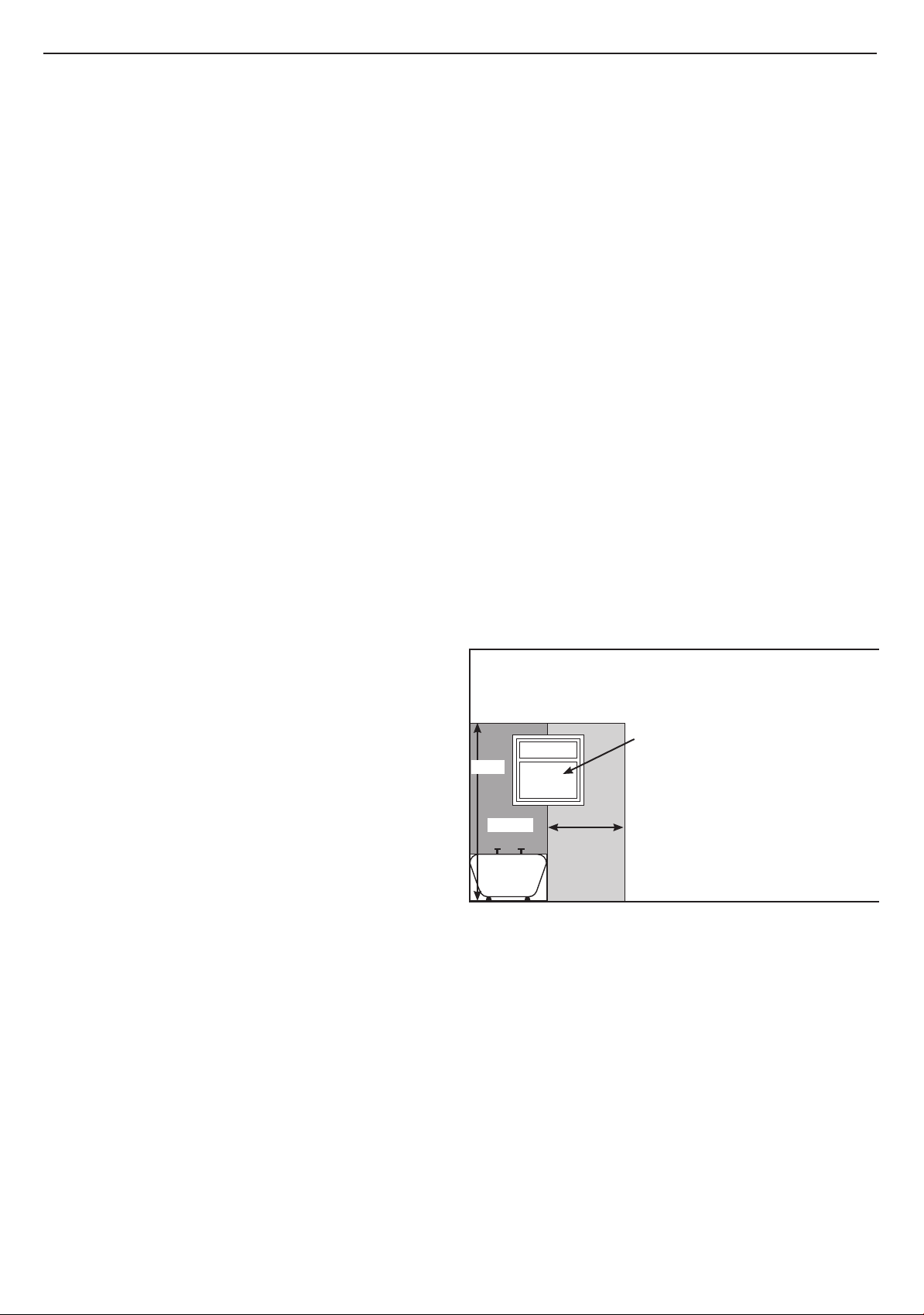
If the appliance is to be installed in a room containing a bath or
shower then, providing water jets are not going to be used for
cleaning purposes (as in communal baths/showers), the appliance
must be installed beyond Zone 2, as detailed in BS.7671.
Compartment Installations
A compartment used to enclose the boiler should be designed and
constructed specially for this purpose.
An existing cupboard or compartment may be used, provided that
it is modied for the purpose.
Braces for compartments must be easily removable for service access.
In both cases, details of essential features of cupboard /
compartment design, including airing cupboard installation, are to
conform to the following:
• BS 6798 (No cupboard ventilation is required - see ‘Air Supply’
for details).
• The position selected for installation MUST allow adequate
space for servicing in front of the boiler.
• For the minimum clearances required for safety and
subsequent service, see the wall mounting template and
Section 1.13. In addition, sufcient space may be required to
allow lifting access to the wall mounting plate.
11
Page 12

SECTION 1 - GENERAL
Pressure drop (mbar )
1.8 GAS SUPPLY
The local gas supplier should be consulted, at the installation
planning stage, in order to establish the availability of an adequate
supply of gas. An existing service pipe must NOT be used without
prior consultation with the local gas supplier.
The boiler MUST be installed on a gas supply with a governed
meter only.
A gas meter can only be connected by the local gas supplier or
by a Gas Safe Registered Engineer. In IE by a Registered Gas
Installer (RGII).
An existing meter should be checked, preferably by the gas
supplier, to ensure that the meter is adequate to deal with the rate
of gas supply required.
It is the responsibility of the Gas Installer to size the gas
installation pipework in accordance with BS6891. Whilst the
principle of the 1:1 gas valve ensures the Keston range is able
to deliver it’s full output at inlet pressures as low as 14mb,
other gas appliances in the property may not be as tolerant.
When operating pressures are found to be below the minimum
meter outlet of 19mb these should be checked to ensure this is
adequate for correct and safe operation.
Allowing for the acceptable pressure loss of 1mb across the
installation pipework, it can be assumed that a minimum permitted
operating pressure of 18mb will be delivered to the inlet of
the appliance. (Reference BS 6400-1 Clause 6.2 Pressure
Absorption).
The external gas cock could further reduce the operating pressure
when measured at its test point. The pressure drop is relative to
the heat input to the boiler (kW), refer to graph below.
Gas Cock Pressure Drop
3
2.5
2
1.5
1
0.5
0
0 10 20 30 40 50
Heat Input to Boiler (kW)
IMPORTANT.
Ensure all gas valve connections are gas tight with a gas
soundness check up to the gas control valve.
Installation pipes must be tted in accordance with BS.6891. In IE
refer to IS.813.
The complete installation MUST be tested for gas tightness and
purged as described in the above code.
1.9 WATER CIRCULATION SYSTEM
IMPORTANT.
A minimum length of 1 metre of copper pipe MUST be tted
to both ow and return connections from the boiler before
connection to any plastic piping.
The central heating system should be in accordance with BS.6798
and, in addition, for smallbore and microbore systems, BS.5449.
WATER TREATMENT - see Section 1.16
1.10 BOILER CONTROL INTERLOCKS
Central heating systems controls should be installed to ensure
the boiler is switched off when there is no demand for heating, in
compliance with Building Regulations.
Heating systems utilising full thermostatic radiator valve control
of temperature in individual rooms should also be tted with a
room thermostat controlling the temperature in a space served by
radiators not tted with such a valve.
When thermostatic radiator valves are used, the space heating
temperature control over a living / dining area or hallway having
a heating requirement of at least 10% of the minimum boiler heat
output should be achieved using a room thermostat, whilst other
rooms are individually controlled by thermostatic radiator valves.
However, if the system employs thermostatic radiator valves on all
radiators, or two port valves, then a bypass circuit must be tted
with an automatic bypass valve to ensure a ow of water should
all valves be in the closed position.
1.11 ELECTRICAL SUPPLY
WARNING.
This appliance must be earthed.
Wiring external to the appliance MUST be in accordance with
the current I.E.E. (BS.7671) Wiring Regulations and any local
regulations which apply. For IE reference should be made to the
current ETCI rules for electrical installations.
The mains supply to the boiler and system wiring centre shall be
through one common fused double pole isolator. For new heating
systems, and where practicable replacement boiler installations,
the isolator shall be situated adjacent to the appliance.
1.12 CONDENSATE DRAIN
Refer to Sections 2.12
A condensate drain is provided on the boiler. This drain must be
connected to a drainage point on site. All pipework and ttings in
the condensate drainage system MUST be made of plastic - no
other materials may be used.
IMPORTANT.
Any external runs must be in accordance with BS 6798.
The drain outlet on the boiler is sized for standard 21.5mm
overow pipe. It is a universal tting to allow use of different
brands of pipework.
12
Installation and Servicing
Page 13
SECTION 1 - GENERAL
395
100
400
700
2.5
2.5
from case
Air Flue
*
19862
89
155
30mm
Minimum Top Clearance
DATA PLATE
Underside View - Pipe Dimensions to Wall
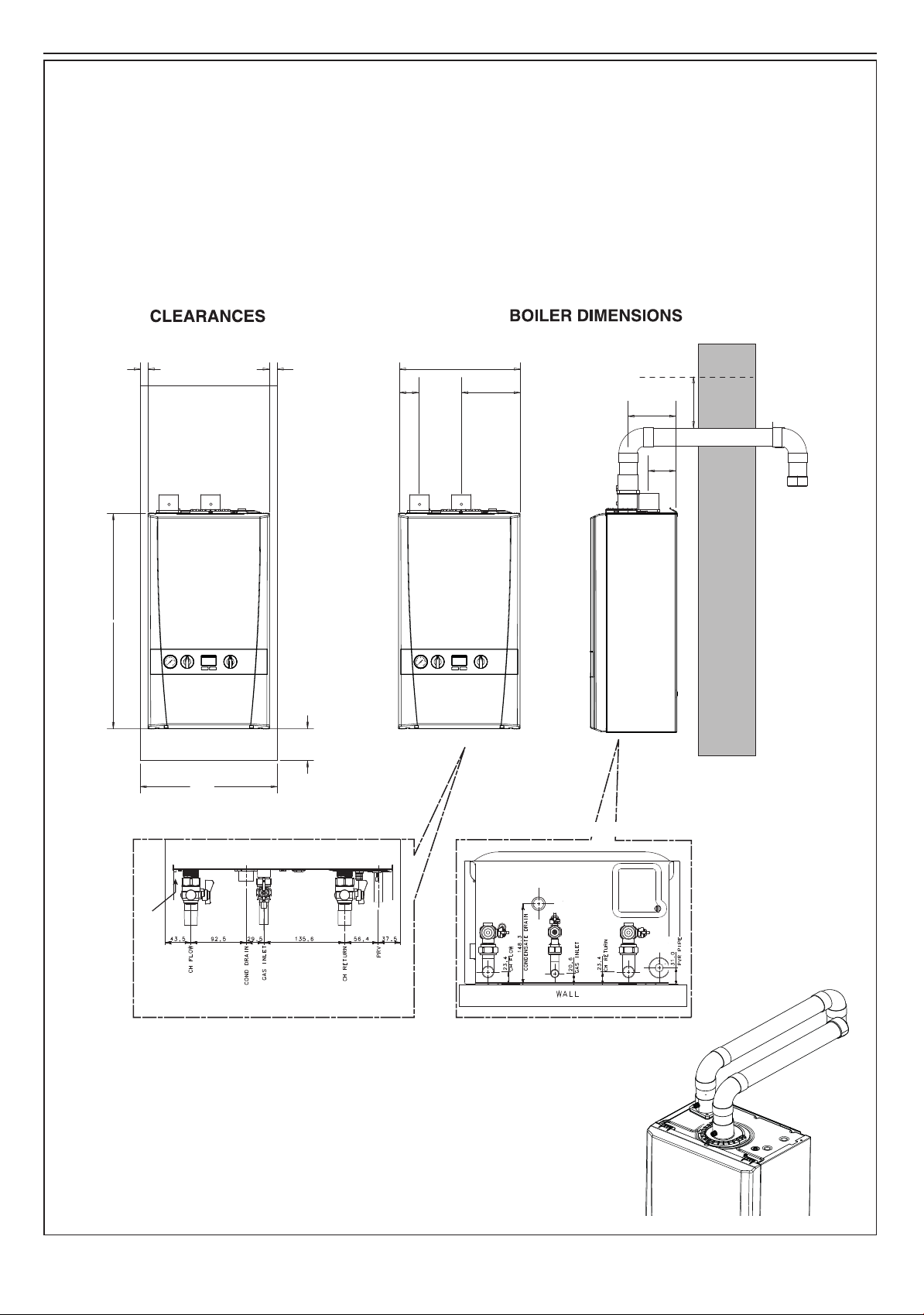
Water Connections and Gas Connection
1.13
BOILER DIMENSIONS, SERVICES & CLEARANCES
The boiler connections are made on the boiler connection tails.
Refer to Section 2.13.
The following minimum clearances must be maintained for
operation and servicing.
Additional space will be required for installation, depending
upon site conditions.
Side and Rear Flue
a. Provided that the ue hole is cut accurately, e.g. with a
core drill, the ue can be installed from inside the building
all dimensions in mm
where wall thicknesses do not exceed 600mm (24”). Where
the space into which the boiler is going to be installed is
less than the length of ue required the ue must be tted
from the outside.
Installation from inside ONLY
b. If a core boring tool is to be used inside the building the
space in which the boiler is to be installed must be at least
wide enough to accommodate the tool.
Front clearance
The minimum front clearance when built in to a cupboard is 5mm
from the cupboard door but 450mm overall clearance is still
required, with the cupboard door open, to allow for servicing.
* Bottom clearance
Bottom clearance after installation can be reduced to 5mm.
This must be obtained with an easily removable panel to provide
the 100mm clearance required for servicing.
Installation and Servicing
13
Page 14
SECTION 1 - GENERAL
CH Return
Ecl 6053
Hose unions
Mains
water supply
Temporary hose
(disconnect after filling)
Additional
stop valve
Double check valve
assembly
(
note direction of flow
)
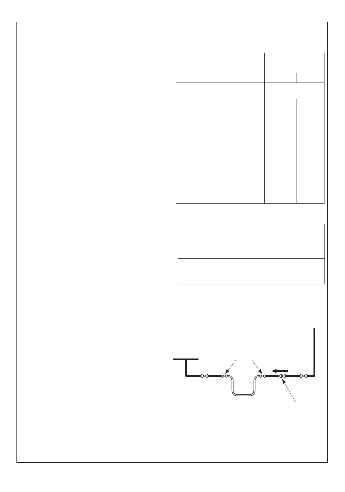
1.14 SYSTEM REQUIREMENTS - Central Heating
Notes
a. The method of lling, relling, topping up or ushing sealed primary
hot water circuits from the mains via a temporary hose connection
is only allowed if acceptable to the local water authority.
b. Antifreeze uid, corrosion and scale inhibitor uids suitable for use
with boilers having aluminium heat exchangers may be used in the
central heating system.
General
1. The installation must comply with all relevant national and local
regulations.
2. The installation should be designed to work with flow
temperatures of up to 86
3. All components of the system must be suitable for a working
pressure of 3 bar and a maximum design temperature of 110 oC.
Extra care should be taken in making all connections so that the
risk of leakage is minimised.
The following components are incorporated within the appliance:
a. Circulating pump.
b. Safety valve, with a non-adjustable preset lift pressure of 3
bar.
c. Pressure gauge, covering a range of 0 to 4 bar.
d. An 8-litre expansion vessel, with an initial charge pressure
of 0.75 bar.
4. ‘Make-up’ Water. Provision must be made for replacing water
loss from the system, either :
a. From a manually lled ‘make-up’ vessel with a readily visible
water level. The vessel should be mounted at least 150mm
above the highest point of the system and be connected
through a non-return valve to the system, tted at least
150mm below the ‘make-up’ vessel on the return side of
the radiators. or
b. Where access to a ‘make-up’ vessel would be difcult, by
pre-pressurisation of the system.
The maximum cold water capacity of the system should
not exceed 143 litres. This is the maximum system
volume for the boiler expansion vessel. If the capacity of
the vessel is not considered sufcient for this, or for any
other reason, an additional vessel MUST be installed on
the return to the boiler.
Guidance on vessel sizing is given in table opposite.
5. Filling
The system may be lled by the following method:
Through a temporary hose connection from a ‘draw-off’ tap,
supplied from a service pipe under mains pressure. Where the
mains pressure is excessive, a pressure reducing valve must be
used to facilitate lling. When installing the lling device, it must
be connected as below to fully comply with the water regulations.
This may involve the tting of an additional WRAS approved
isolator valve to the mains supply.
i. Thoroughly ush out the whole system with cold water.
ii. Fill and vent the system until the pressure gauge registers 1.5
bar, and examine for leaks.
iii. Check the operation of the safety valve by raising the water
pressure until the valve lifts. This should occur within 0.3 bar
of the preset lift pressure.
iv. Release water from the system until the minimum system
design pressure is reached; 1.0 bar if the system is to be prepressurised.
o
C.
Safety valve setting bar 3.0
Vessel charge pressure bar 0.5 to 0.75
System pre-charge pressure bar None 1.0
System volume Expansion vessel
(litres) volume (litres)
25 1.6 1.8
50 3.1 3.7
75 4.7 5.5
100 6.3 7.4
125 7.8 9.2
150 9.4 11.0
175 10.9 12.9
190 11.9 14.0
200 12.5 14.7
250 15.6 18.4
300 18.8 22.1
For other system volumes
multiply by the factor across 0.063 0.074
Model 30
Max CH uutput kW 30.3
Water ow rate l/min 21.5
(gal/min) (4.7)
o
Temp differential
C 20
Head available m.w.g. 1.9
for system (ft.w.g.) (6.2)
14
Installation and Servicing
Page 15

SECTION 1 - GENERAL
1.15 SYSTEM BALANCING
The boiler does not normally need a bypass but at least some radiators on the heating circuit, of load of at least 10% of the
minimum boiler output, must be provided with twin lockshield valves so that this minimum heating load is always available. See
note regarding thermostatic radiator valves on page 12.
Note. Systems incorporating zone valves which could completely cut off the ow through the system must also include a bypass.
BALANCING
1. Set the programmer to ON.
Close the manual or thermostatic valves on all radiators,
leaving the twin lockshield valves (on the radiators referred
to above) in the OPEN position.
Turn up the room thermostat and adjust the lockshield
valve to give an uninterrupted ow through the radiator.
These valves should now be left as set.
2. Open all manual or thermostatic radiator valves and adjust
the lockshield valves on the remaining radiators, to give
around 20
3. Adjust the room thermostat and programmer to NORMAL
settings.
o
C temperature drop at each radiator.
1.16 WATER TREATMENT
CENTRAL HEATING
The Keston System S range of boilers have an ALUMINIUM
alloy heat exchanger.
IMPORTANT.
The application of any other treatment to this product may
render the guarantee of Keston Invalid.
Keston recommend Water Treatment in accordance with the
Benchmark Guidance Notes on Water Treatment in Central
Heating Systems.
If water treatment is used Keston recommend only the use of
SCALEMASTER GOLD 100, FERNOX, MBI, ADEY MC1, SENTINEL
X100 OR CALMAG CM100 inhibitors and associated water
treatment products, which must be used in accordance with the
manufacturers’ instructions.
Notes.
1. It is most important that the correct concentration of the
water treatment products is maintained in accordance with
the manufacturers’ instructions.
2. If the boiler is installed in an existing system any unsuitable
additives MUST be removed by thorough cleansing. BS
7593 details the steps necessary to clean a domestic heating
system.
3. In hard water areas, treatment to prevent lime scale may be
necessary - however the use of articially softened water is
NOT permitted.
For further information contact:
Fernox Cookson Electronics
Forsyth Road
Sheerwater
Woking
Surrey GU21 5RZ
+44 (0) 0870 601 5000
Sentinel Performance Solutions
The Heath Business & Technical Park
Runcorn
Cheshire WA7 4QX
Tel: 0800 389 4670
www.sentinel-solutions.net
Scalemaster Water Treatment Products
Emerald Way
Stone
Staffordshire ST15 0SR
Tel: +44 (0) 1785 811636
Calmag Ltd.
Unit 3-6, Crown Works
Bradford Road
Sandbeds, Keighley
West Yorkshire BD20 5LN
Tel: +44 (0) 1535 210 320
Adey Professional Heating Solutions
Gloucester Road,
Cheltenham GL51 8NR
Tel: +44 (0) 1242 546700
4. Under no circumstances should the boiler be red before the
system has been thoroughly ushed.
Installation and Servicing
15
Page 16
SECTION 1 - GENERAL
506
504
227
224
503
505
313
215
309
308
306
217
307
401
218
211
304
214
223
325
302
104
114
117
118
507
203
105
231
229
228
116
115
219
324
135
110
113
120
108
121
206
205
204
131
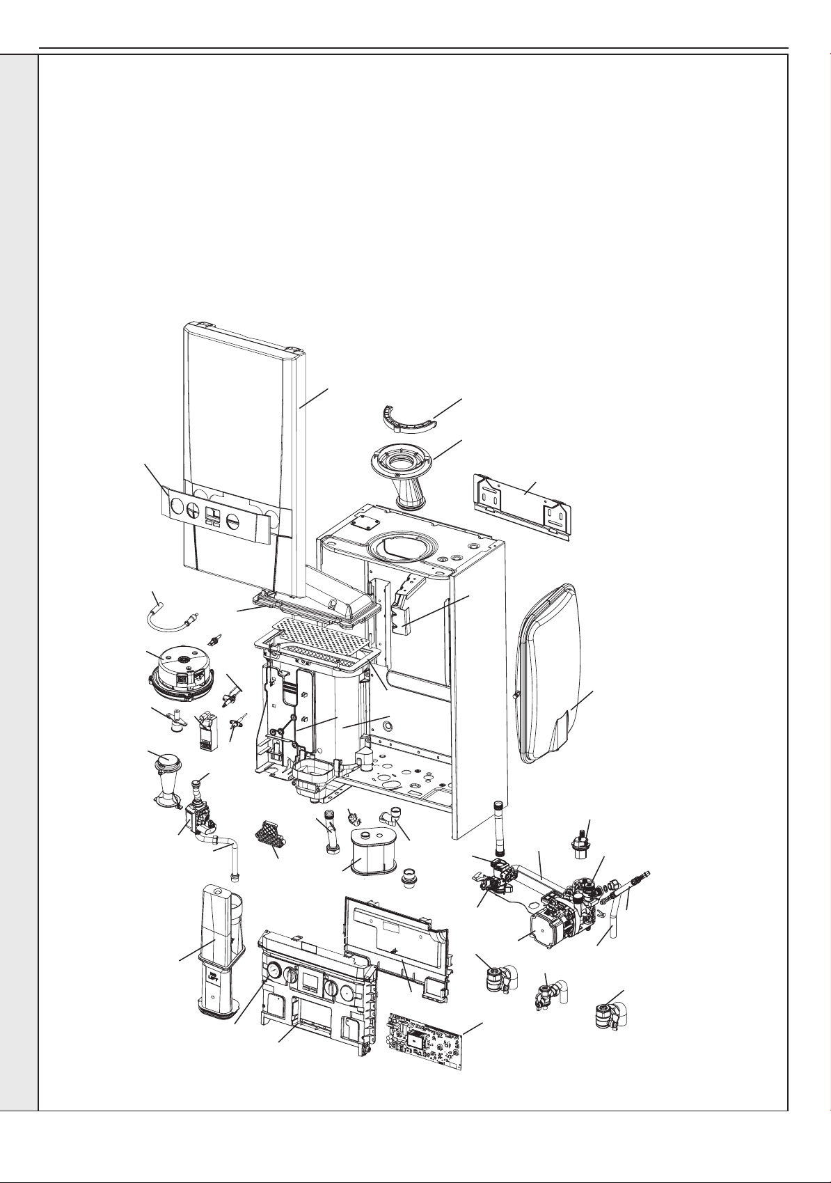
1.17 BOILER ASSEMBLY - Exploded View
Note that item numbers are linked to the spares list
104 CH RETURN VALVE
105 CH FLOW VALVE
108 PUMP HEAD
110 PUMP AUTO AIR VENT
113 PRESSURE RELIEF VALVE
114 PIPE - PRV OUTLET
115 PIPE - FLOW
116 PIPE - RETURN
117 PIPE - EXPANSION VESSEL
118 EXPANSION VESSEL
120 FLOW GROUP MANIFOLD
121 BY-PASS KIT
131 WATER PRESSURE SWITCH
135 PRESSURE GAUGE
203 GAS COCK
204 PIPE - GAS INLET
205 GAS VALVE
206 PIPE - GAS INJECTOR
211 INJECTOR ASSEMBLY
214 VENTURI
215 FAN
217 BURNER
218 GASKET - BURNER
219 SUMP CLEAN OUT COVER
223 FLUE MANIFOLD
224 FLUE MANIFOLD TOP
227 CLAMP RETAINING FLUE TURRET
228 HOSE CONDENSATE INTERNAL
229 SIPHON TRAP
231 CONDENSATE OUTLET CONNECTION
302 PCB
304 CONTROL THERMISTOR (RETURN)
INSTALLATION
306 ELECTRODE IGNITION
307 ELECTRODE DETECTION
308 IGNITER UNIT
309 THERMISTOR CONTROL/NO FLOW
313 IGNITION LEAD
324 CONTROLS BOX LID
325 CONTROL BOX FRONT
401 HEAT ENGINE
503 WALL MOUNTING BRACKET
504 FRONT PANEL
505 FASCIA
506 BRACKET - GAS VALVE
507 BRACKET - EXPANSION VESSEL
16
Installation and Servicing
Page 17
SECTION 1 - GENERAL
F
C
A
D
G
B
E
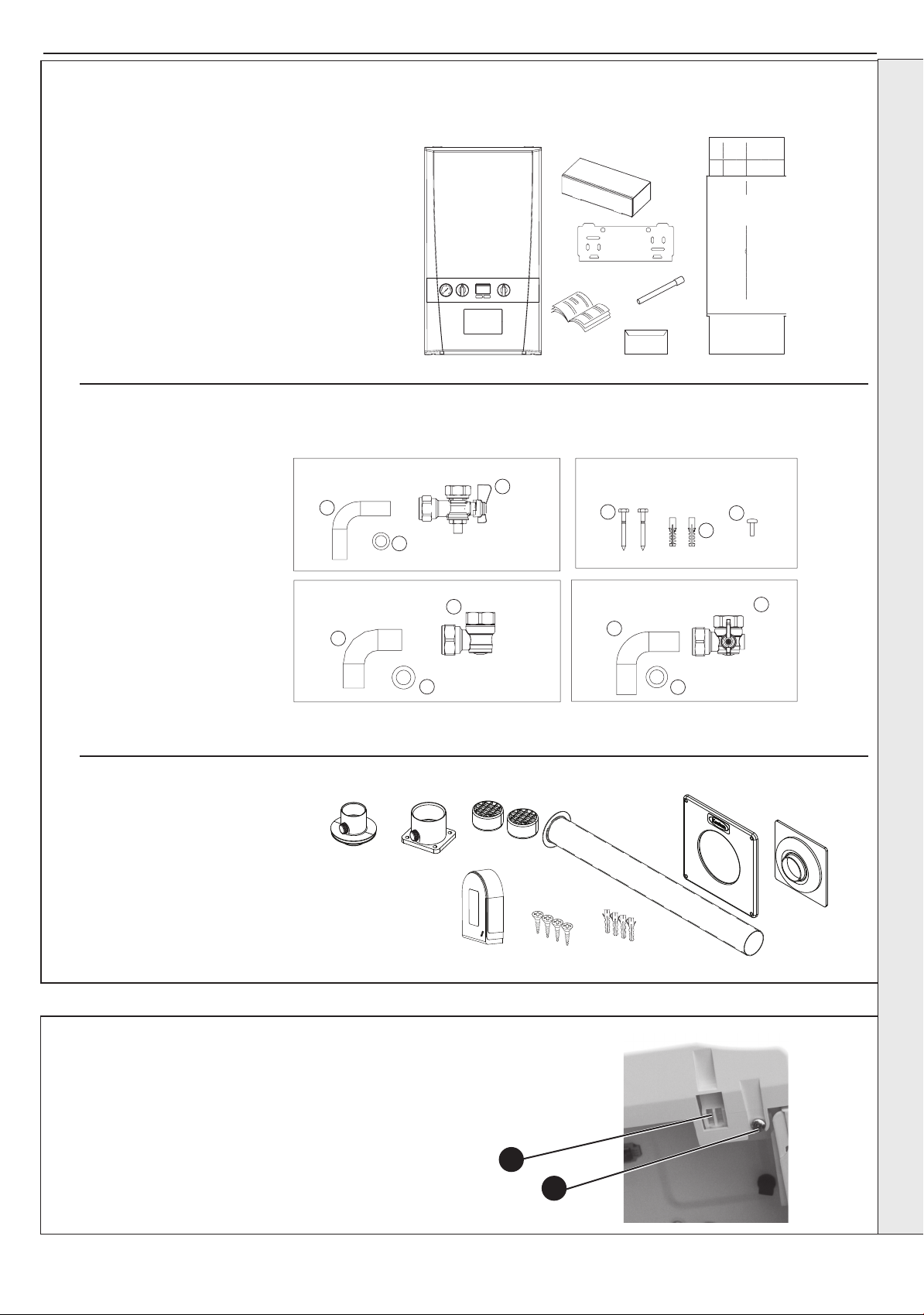
Boiler Guarantee
HARDWARE PACK CONTENTS
Gas Valve Pack
1. Pipe - Gas Inlet
2. Washer - Gas (blue)
3. Gas Cock
Return Valve Pack
1. Pipe CH Return
2. Washer CH
3. Valve Return
Accessory Pack
1. Screw (x2)
2. Wallplug (x2)
3. Turret Clamp Screw (spare) (x1)
Flow Valve Pack
1. Pipe CH Flow
2. Washer CH
3. Valve Flow
Gas Valve Pack
Accessory Pack
Flow Valve Pack
Return Valve Pack
1
1
1
1
2
3
3
2
2
2
3
3
1.18 UNPACKING
Unpack and check the contents.
Pack A Contents
A Boiler
B Hardware Pack Box
C Wall Mounting Plate
D These Installation/Users Instructions
E Wall Mounting Template
(located on internal protective packaging)
F Safety Valve Drain Pipe
G Boiler Guarantee & Registration Pack
INSTALLATION
Flue Pack Contents
A Flue Adaptor
B Air Spigot
C Terminals - 2 off
D Flue Sleeve
E Wall Plate
F Wall Seal
G Outside Sensor
H Screws - 4 off
J Wall Plugs - 4 off
1.19 FRONT PANEL REMOVAL
1. Loosen the 2 screws retaining the front panel.
2. Pull the two clips downwards to disengage.
3. Pull the front panel forward and upwards to remove.
Installation and Servicing
A
B
G
C
D
H
J
E
F
2
1
17
Page 18
SECTION 2 - INSTALLATION
2.1 FLUE SYSTEM
IMPORTANT
When installing a replacement boiler a new ue system is recommended. However re-using the existing
boiler ue installation is acceptable if the installer checks and conrms:
• The ue pipe is the approved Marley/Polypipe/Terrain/Wavin 50mm muPVC solvent weld ue system
• The ue installation is upgraded to the most recent ue standards taking particular care to comply with
ues in voids
• A risk assessment is conducted to conrm the effectiveness of the ue
• The existing ue will last the lifetime of the new appliance
DESIGN
Individual air supply and ue outlet pipes are used as standard.
The material approved for this application which MUST be used are:
- Marley muPVC Solvent Weld System (50mm)
- Polypipe System 2000 muPVC solvent weld (50mm)
- Polypipe Terrain 200 muPVC Solvent Weld System (50mm)
- Wavin OSMA PVC-C Solvent Weld System (50mm)
to BS5255 and/or BSEN1566-11 and BSEN1329, are the only systems approved for this application.
The following pipe and ttings are approved.
Polypipe System 2000 muPVC solvent Weld System (50mm)
Polypipe Code
MU 301 4m length muPVC wastepipe 5/225
MU 313 50mm x 45 deg muPVC obtuse bend
MU 314 50mm x 92.5 deg muPVC swept bend
MU 310 50mm muPVC straight coupling
MU 316 50mm x 92.5 deg muPVC swept tee
Marley muPVC Solvent Weld System (50mm)
Marley Code
KP 304 50mm x 4m double spigot pipe
KP32 50mm x 45 deg bend
KSC3 50mm straight coupling
KB3 50mm x 88.5 deg bend
KT3 50mm swept tee
Polypipe Terrain Solvent Weld System (50mm)
Polypipe Code
200.2.40 4m length muPVC wastepipe
201.2.135 50mm x 135 deg muPVC bend
1
200.2.91 50mm x 91
210.2 50mm muPVC straight coupling
204.2.135 50mm muPVC swept tee
Wavin OSMA PVC-C Solvent Weld System (50mm)
Wavin Code
2M073 3M lenght waste pipe 50mm
2M163 50mm x 45 deg bend
2M161 50mm x 87.5 deg bend
2M104 50mm double socket
2M190 50mm x 8.75 tee
/4 deg muPVC swept bend
Consideration MUST be given to expansion and contraction of the ue. Refer to Assembly Practice (Section 2.10) in this
installation and Servicing Instructions for further guidance.
FLUE OUTLET
18
Installation and Servicing
continued............
Page 19
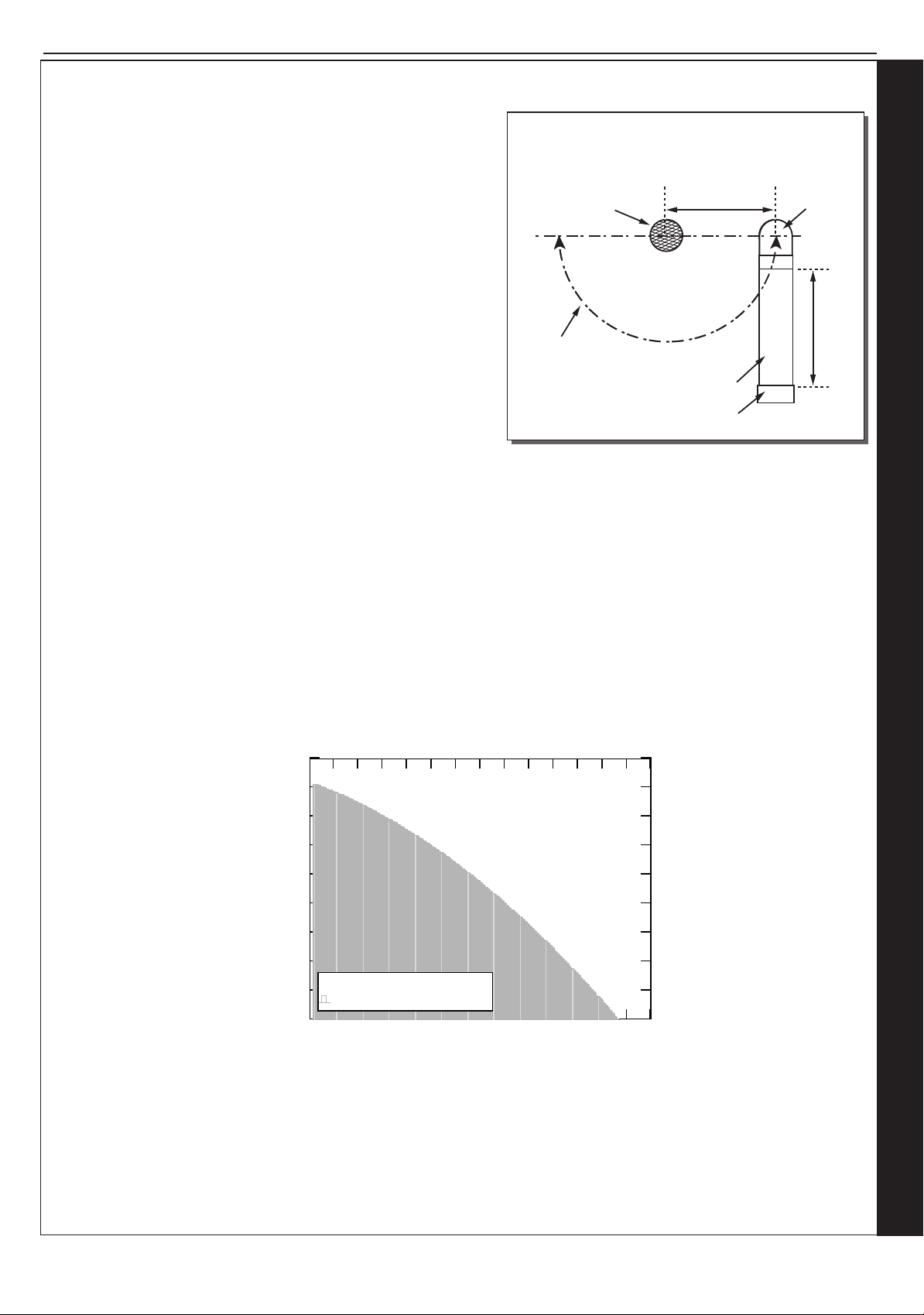
SECTION 2 - INSTALLATION
TERMINAL POSITIONS
Flue
Pipe
Elbow
Minimum Separation
140mm
Acceptable
range of air
pipe siting
Terminal
Air Pipe
150mm
2
4
6
8
10
12
14
16
18
20
22
24
26
28
30
2
6
10
14
18
22
26
30
34
38
Accep t able Op erating Area
Keston System 30 - Flue & Air Pipe Length
Flue Pip e Length [m]
Air Pipe Length [m]
............. CONT’D
TERMINATION OF THE FLUE AND AIR
The ue and air pipes may terminate independently through any
external walls within the same dwelling except on opposing walls,
within the maximum lengths shown in graph below. (Alternatively a
vertical ue pipe termination is acceptable.)
The air pipe must have an elbow and 150mm length of pipe directed
downwards with a termination grill tted.
The air pipe can be situated at the side or beneath the ue pipe to a
minimum dimension of 140mm (see diagram opposite). It must not be
sited above the ue pipe.
The ue and air pipes must extend by at least 40mm from the wall
surface.
Condensing boiler emit a visible plume of water vapour from the
ue terminal, this is normal. It is the responsibility of the installer to
judiciously select a terminal location that does not cause a nuisance.
If either the ue or air terminal is below a height of 2m from ground
level a terminal guard must be tted.
MAXIMUM LENGTHS
Due to the resistance presented by extended ue length a slight reduction in maximum boiler output will occur where
combined ue and air lengths in excess of 18.0m (50mm muPVC) are used. In such cases the boiler output will be reduced by
0.6% per additional metre.
The maximum lengths of both air inlet pipe and ue outlet pipe, when no bends are used, are as detailed in graph below.
However, each bend used has an equivalent length that must be deducted from the maximum straight length stated in graph
below. Knuckle bends must not be tted.
A 92.5º swept elbow is equivalent to 1.0m straight length. A 45º bend is equivalent to 0.5m straight length.
It is possible to have variable ue and air lengths as described within the shaded area of graph below.
SLOPE
‘Horizontal’ ue outlet pipework MUST slope at least 1.5 degrees (26mm per metre run) downwards towards the boiler. Pipework
can be vertical. Only swept elbows can be used.
Air inlet pipework can be truly horizontal or vertical, or sloping in a downward direction towards the boiler but in each case rain, etc.,
must be prevented from entering the pipe. There must be no troughs in any of the pipework, whether it be air inlet or ue
outlet.
Installation and Servicing
FLUE OUTLET
19
Page 20
SECTION 2 - INSTALLATION
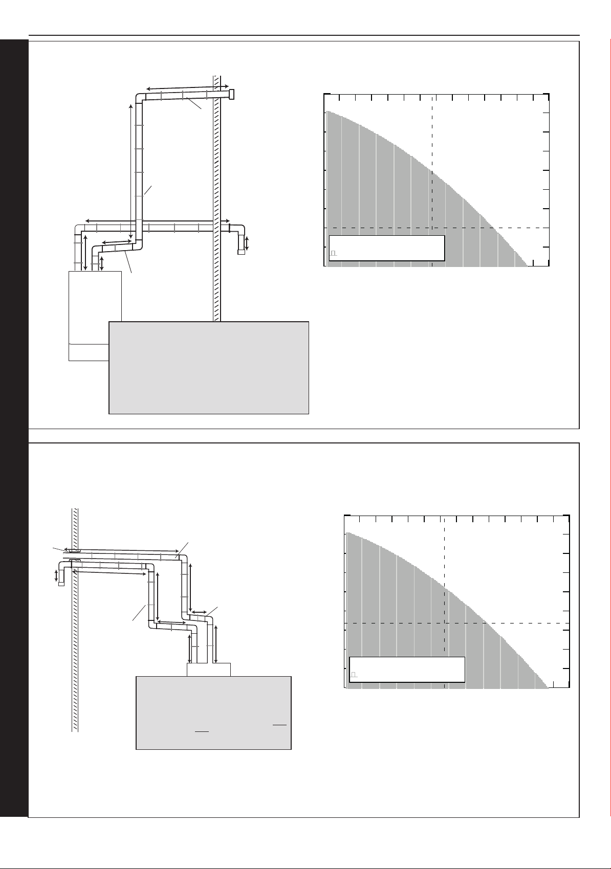
6m
2m
Bracket at
each 1 metre
1m
4m
1.5m
6m
1.5º back
to boiler
1.5º back
to boiler
Air
Elbows 2 x 1m = 2m
Straights 6+2+0.15 = 8.15m
Total = 10.15m
Overall Flue / Air = 25.65m
Flue
Elbows 3 x 1m = 3m
Straights 4+6+1.5+1 = 12.5m
Total = 15.5m
Calculations
0.15m
2 4 6 8 10
12
14
16
18
20
22
24
26
28
30
2
6
10
14
18
22
26
30
34
38
Accep t able Op erating Area
Keston System 30 - Flue & Air Pipe Length
Flue Pip e Length [m]
Air Pipe Length [m]
10.15
15.5
2 4 6 8 10
12
14
16
18
20
22
24
26
28
30
2
6
10
14
18
22
26
30
34
38
Accep t able Op erating Area
Keston System 30 - Flue & Air Pipe Length
Flue Pip e Length [m]
Air Pipe Length [m]
15.65
14.5
2.2 FLUE INSTALLATION EXAMPLE KESTON SYSTEM S 30
2.3 FLUE INSTALLATION EXAMPLE KESTON SYSTEM S 30
Sleeve
Air
0.15m
FLUE OUTLET
20
4m
4m
Bracket every
1 metre
Air
4 x 90º elbows 4
Straight lengths 2
2
3.5
4
0.15
15.65
1.5º back
to boiler
3.5m
3.5m
1.5m
2m
2m
Calculations
Overall Flue / Air = 30.15m
1.5º back
to boiler
2.5m
Flue
3 x 90º elbows 3
Straight lengths 2.5
1.5
3.5
4
14.5
Installation and Servicing
Page 21
SECTION 2 - INSTALLATION
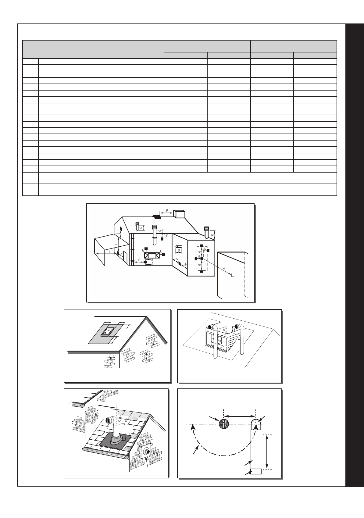
2.4 FLUE TERMINATION POSITION
Twin Flue Positions
When Flue & Air Terminals are
less than 500mm apart
When Flue & Air Terminals are
more than 500mm apart
Flue min. spacing Air min. spacing Flue min. spacing Air min. spacing
A Below an opening (1) 300mm 50mm 300mm 50mm
B Above an opening (1) 300mm 50mm 300mm 50mm
C Horizontally to an opening 300mm 50mm 300mm 50mm
D Below gutters,soil pipes or drain pipes 75mm 75mm 75mm 75mm
E Below eaves 200mm 50mm 200mm 50mm
F Below balcony or car port roof 200mm 50mm 200mm 50mm
G From a vertical drain pipe or soil pipe 150mm 50mm 150mm 50mm
H From an internal or external corner or to a boundary
200mm 50mm 200mm 50mm
alongside the terminal (2)
I Above ground,roof or balcony level 300mm 100mm 300mm 100mm
J From a surface or boundary facing the terminal 600mm 100mm 600mm 100mm
K From a terminal facing a terminal 1200mm 1200mm 1200mm 1200mm
L From an opening in the car port into the building 1200mm 100mm 1200mm 100mm
M Vertically from a terminal on the same wall 1500mm 1500mm 1500mm 1500mm
N Horizontally from a terminal on the same wall 300mm 300mm 300mm 300mm
O From the wall on which the terminal is mounted 40mm 40mm 40mm 40mm
P From a vertical structure on the roof NA NA 300mm NA
Q Above intersection with roof NA NA 150mm NA
,(1) In addition, for temperature and structural reasons, the terminal should not be nearer than 150 mm (fanned draught) to an
opening in the building fabric formed for the purpose of accommodating a built-in element such as a window frame
,(2) The reference to external corners does not apply to building protrusions not exceeding 450 mm, such as disused chimneys on
external walls for: fanned draught appliances
When running flue pipes vertically
they MUST be a minimum of 140mm apart
and termination MUST comply with Section 2.1 an 2.4.
A
A
B
A = 600mm
B = 2000mm
The flue terminal shall not penetrate
the shaded area of the roof
Pitched roof with structure
300mm
min
150mm
min
A
RF9807
If chimney penetrates dotted area such that
A is less than 300mm,
B shall not be less than 300mm.
TERMINAL POSITIONS
Flue
Pipe
Minimum Separation
140mm
Elbow
150mm
Installation and Servicing
Vertical termination must have an
elbow with terminal fitted directed from
roof, 150mm above roof intersection
with air taken from side wall or low level
(min 500mm separation).
Air Terminal
Acceptable
range of air
pipe siting
Air Pipe
Terminal
FLUE OUTLET
21
Page 22
SECTION 2 - INSTALLATION
..............FLUE TERMINATION
GENERAL INSTALLATIONS
All parts of the system must be constructed in accordance with BS 5440 Part 1, except where specically mentioned in these
instructions.
All pipe work must be adequately supported.
All joints other than approved push-on or plastic compression connectors must be made and sealed with solvent cement suitable
for muPVC pipes and conforming to BS 6209.
Consideration must be given to Corgi/Gas Safe bulletin TB200/TB008 regarding ues in voids.
The boiler casing must always be correctly tted to the boiler when leaving the appliance operational.
External wall faces and any internal faces of cavity walls must be good.
AIR SUPPLY
The Keston System is a room-sealed appliance and therefore does not require purpose provided ventilation to the boiler room for
combustion air.
COMPARTMENT INSTALLATION
Due to the low casing temperatures generated by the boiler, no compartment ventilation is required. However, the cupboard or
compartment must not be used for storage.
2.5 INSTALLING THE BOILER
Installation of the boiler is straightforward but consideration must be given to access to allow ue and air pipes to be pushed
through walls and ceilings. The order in which the components are installed will depend upon particular site conditions, but in
general it will be easiest and most accurate to install the boiler and then build up the ue outlet and air inlet pipes to the terminal this is the sequence described.
2.6 WALL MOUNTING TEMPLATE
The wall mounting template is located on the internal protective packaging.
Note.
The template shows the positions of the xing holes and the rear ue hole centre for
standard installation. Care MUST be taken to ensure the correct holes are drilled.
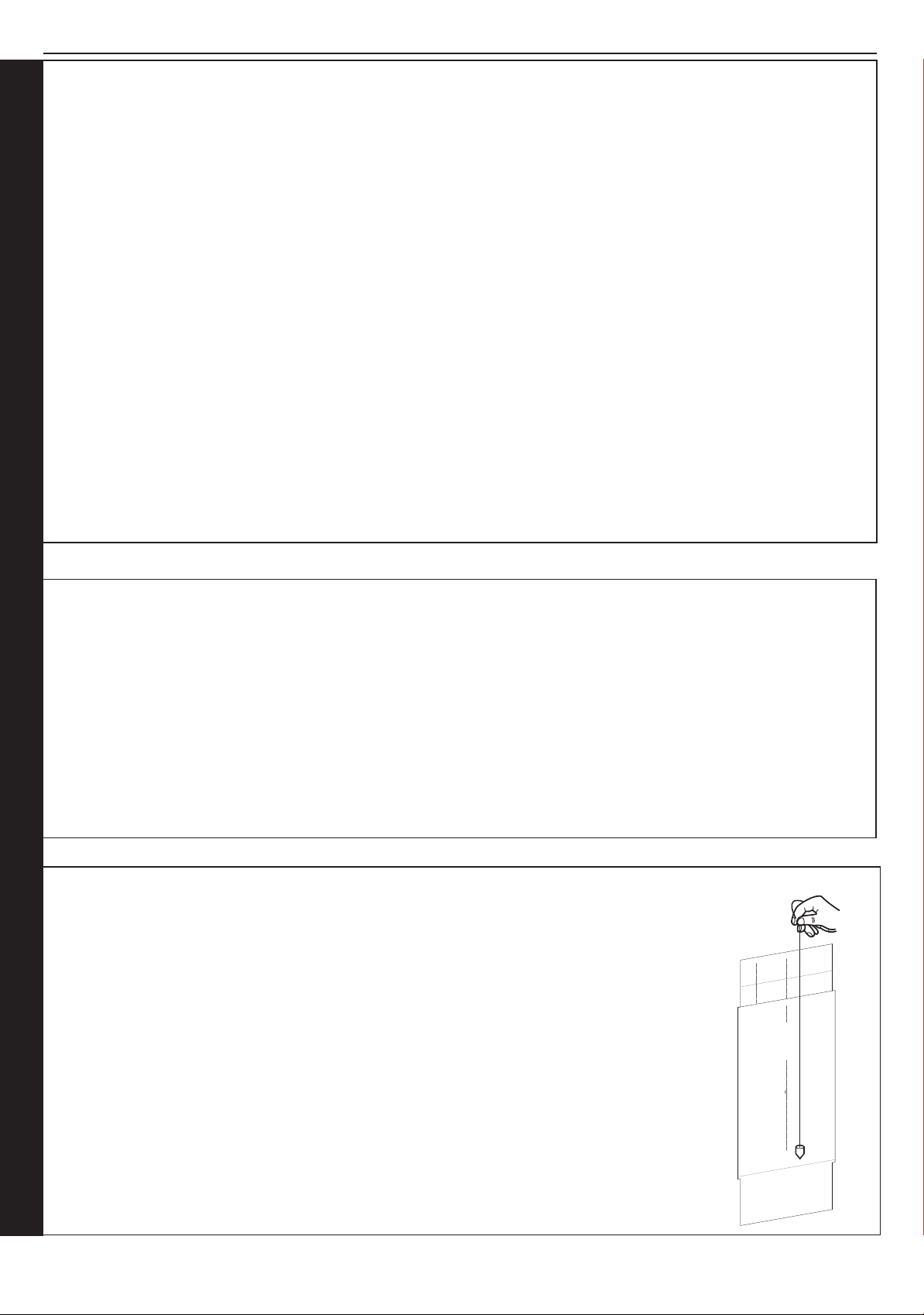
1. Tape template into the selected position. Ensure squareness by hanging a plumbline
as shown.
2. If tting a side ue extend the ue centre line onto the side wall and measure in
155mm for standard installation.
3. Mark onto the wall the following:
a The wall mounting plate screw positions (choose one from each group).
b. The position of the ue duct hole (see diagram below).
Note. Mark the centre of the hole as well as the circumference.
4. Remove the template from the wall.
FLUE OUTLET
22
Installation and Servicing
Page 23
SECTION 2 - INSTALLATION
3G9948
Example of fixing
3G10030
X
Section
through wall
Note. Check all of the hole
positions before drilling.
Rear flue only
60mm diameter
holes
2.7 PREPARING THE WALL
IMPORTANT.
Ensure that, during the cutting operation, masonry falling
outside of the building does not cause damage or personal
injury.
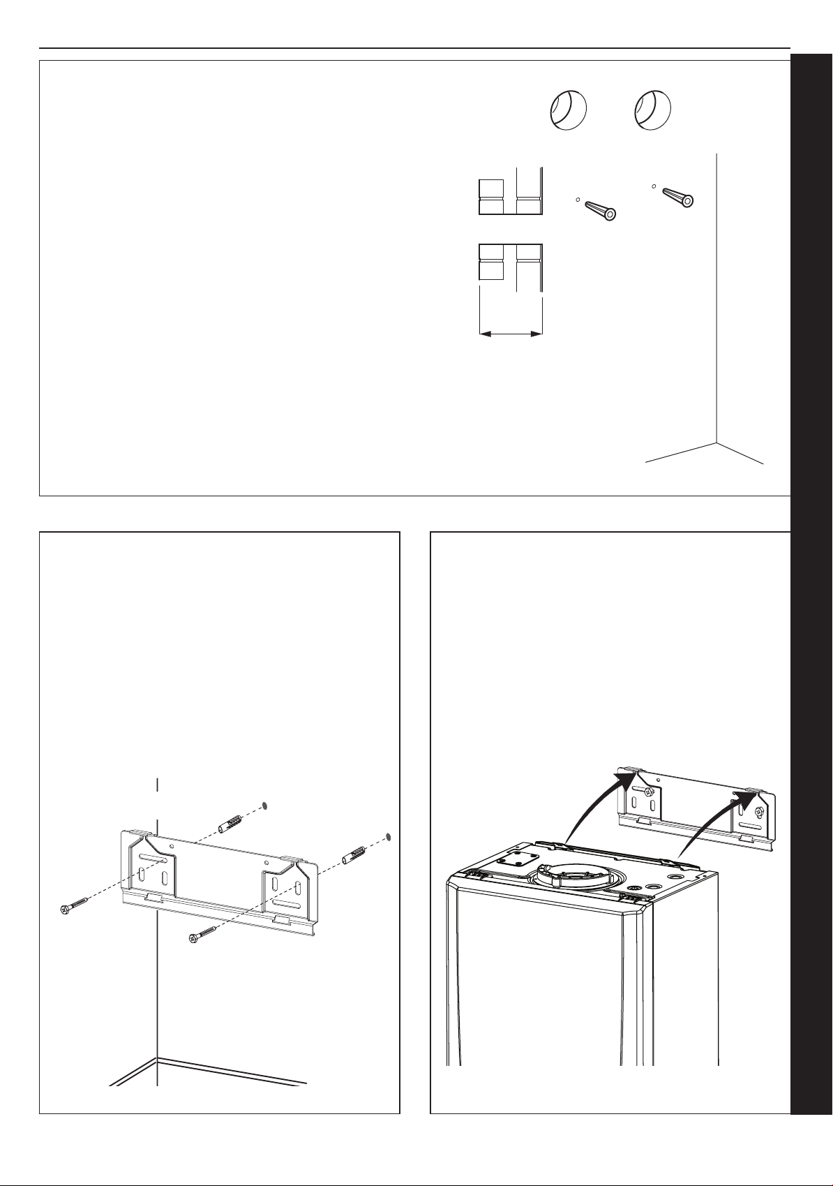
1. Cut the ue and air holes (preferably with 60mm core bore
tool) ensuring the holes are square to the wall.
2. Drill 2 holes with a 7.5mm / 8mm masonry drill and insert
the plastic plugs, provided, for the wall mounting plate.
3. Locate 2 No.14 x 50mm screws in the wall mounting plate
(one at each side, in any of the 3 holes provided at each
side) and screw home.
2.8
FITTING THE WALL MOUNTING PLATE
Screw the wall mounting plate to the wall using 2 wall plugs
(previously tted) with the 2 screws provided.
Choose one of the 2 sets of slots in left and right bank.
Ensuring that at least one of the screws is tted into a top
slot.
2.9 MOUNTING THE BOILER
1. Ensure the plastic plug is removed from the CH
connections before mounting the boiler.
2. Lift the boiler onto the wall mounting plate (refer to the
Introduction section for safe handling advice), locating it
over the two tabs.
Installation and Servicing
FLUE OUTLET
23
Page 24
2.10 ASSEMBLY PRACTICE
SECTION 2 - INSTALLATION
Remove all plastic debris and burrs when installing air intake
piping. Plastic llings caused by cutting muPVC pipe must
not be allowed to be drawn into the combustion air blower.
Prevent dust entering the air intake when cutting on building
sites. Blower failure which is determined to be caused by
plastic lings or other debris will not be covered by guarantee.
INSTALLING FLUE AND AIR PIPES
Important - When installing a replacement boiler, a new ue
system is recommended.
However re-using the existing boiler ue installation is
acceptable if the installer adheres to Section 2.3 Flue System
- Important, and also checks and conrms the following:
• Remove the ue adaptor and air spigot from the ue pack
supplied with the boiler.
• Remove boiler front panel - Section 3.2.
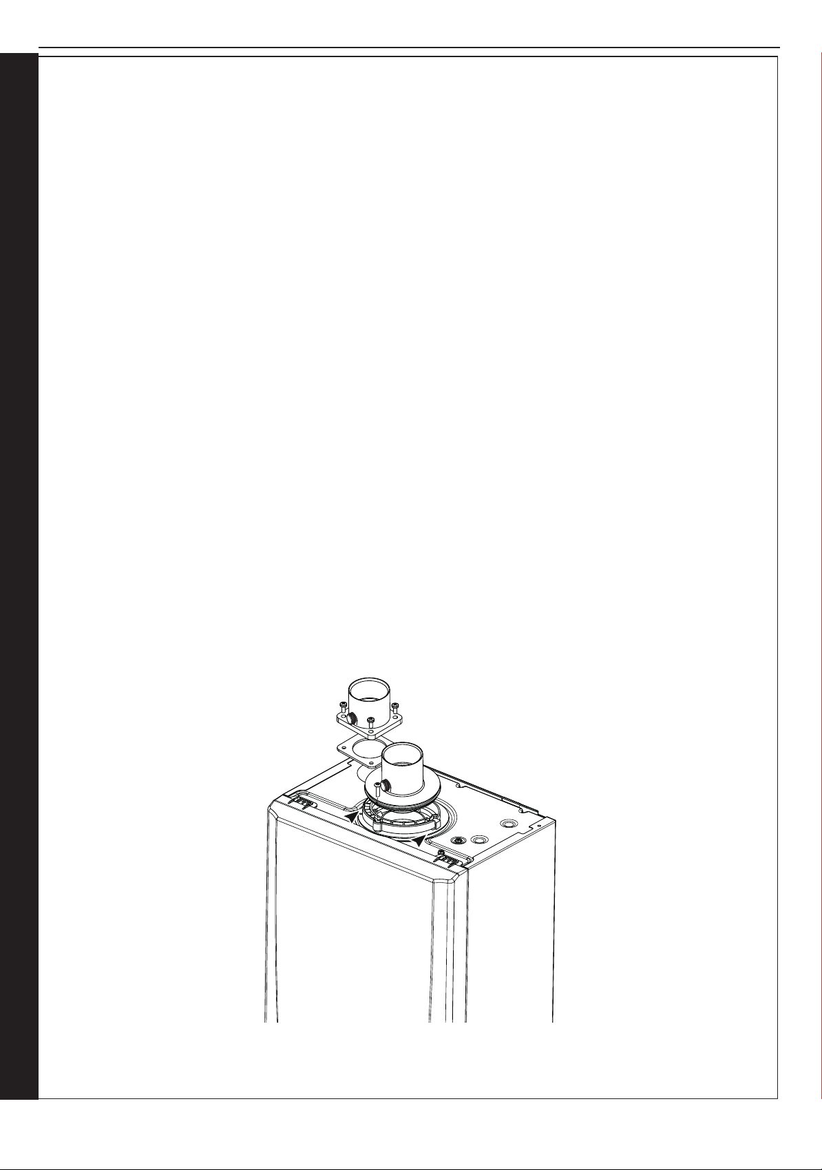
• Remove air intake blanking plate by unscrewing 4 x M5
screws and put to one side, leaving sponge gasket in place.
• Fix air spigot to boiler using the 4 M5 screws, see diag.
below. Ensure sponge gasket is in place and not damaged.
• Insert the ue adaptor into the ue manifold on the top
of the boiler and secure using the clamp provided in
the packaging box, see diagram below. Ensure the
condensate trap/siphon is lled with water.
• Measure, cut and check the air and ue pipes to pass to
the exit from the wall(s) or ceiling.
• Always thoroughly deburr all pipes and most important,
remove shavings from within the pipe.
• Assemble, using solvent weld cement, the pipework from
the boiler connections to the exit from the rst wall/ceiling,
(remount the boiler if removed). When pushing pipe
through walls, ensure grit and dust is not allowed to enter
the pipe.
Ensure pipes are fully engaged into sockets and
solvent welded with no leaks.
• Using the same methods drill any further holes (always
covering existing pipework), cut and assemble the
pipework.
• From outside, complete the two terminations - See
Section 2.1 Flue System and make good all holes. (Wall
sealing collars are available to make good hole areas on
the wall face (part number C.08.0.00.07.0).
• Support any pipes whose route could be displaced
either of its own accord or by accident. Any horizontal
run over 1m or vertical runs of any length must
always be supported. Brackets should be placed at
intervals of approximately 1m. Brackets should be
loose enough on the pipe to allow thermal expansion
and contraction movement.
• Flue pipework through walls MUST be sleeved to
allow thermal expansion and contraction movement.
• Check all connections for security and re-seal any joints
using solvent cement where soundness may be in doubt.
Note. It is equally important to seal the air inlet with solvent
cement as the ue outlet pipe joints.
FLUE OUTLET
24
Installation and Servicing
Page 25
SECTION 2 - INSTALLATION
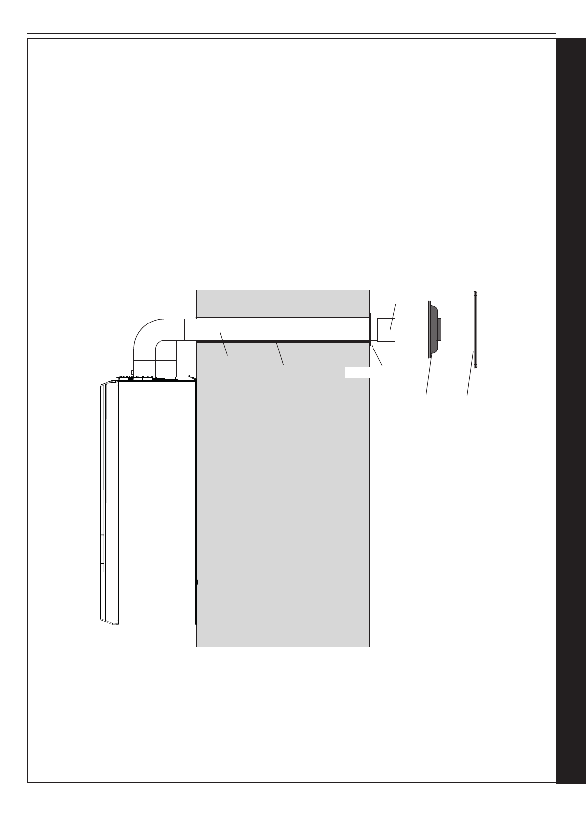
2.11 FITTING THE SLEEVING
1. Cut hole in wall.
2. Measure wall Thickness
3. Cut sleeve length to match wall thickness & remove burrs.
4. Grout sleeve into wall with ange on external face.
5. Slide ue pipe into sleeve, checking it is free to slide.
6. Slide Flexible wall seal over ue pipe and push centre ring up to sleeve ange when cold.
7. Locate wall plate over exible wall seal and clamp in place using the raw plug pack.
8. Afx ue terminal
9. During boiler test check that the ue end is free to expand and contract with exible wall seal.
Flue
Terminal
Flue Pipe
Flue Sleeve
Flue Sleeve Flange
Flexible
Wall
Seal
Wall
Plate
Installation and Servicing
FLUE OUTLET
25
Page 26
SECTION 2 - INSTALLATION
137
47
148
Condensate
Drain
Sink/basin/
bath or
shower
Boiler
with 75mm
sealed
condensate
trap
Min Ø 19mm
Internal pipe
Internal soil & vent stack
Boilers without 75mm sealed
condensate trap must be fitted with
a 75mm trap and visible air break
75
≥ 100
≥ 100
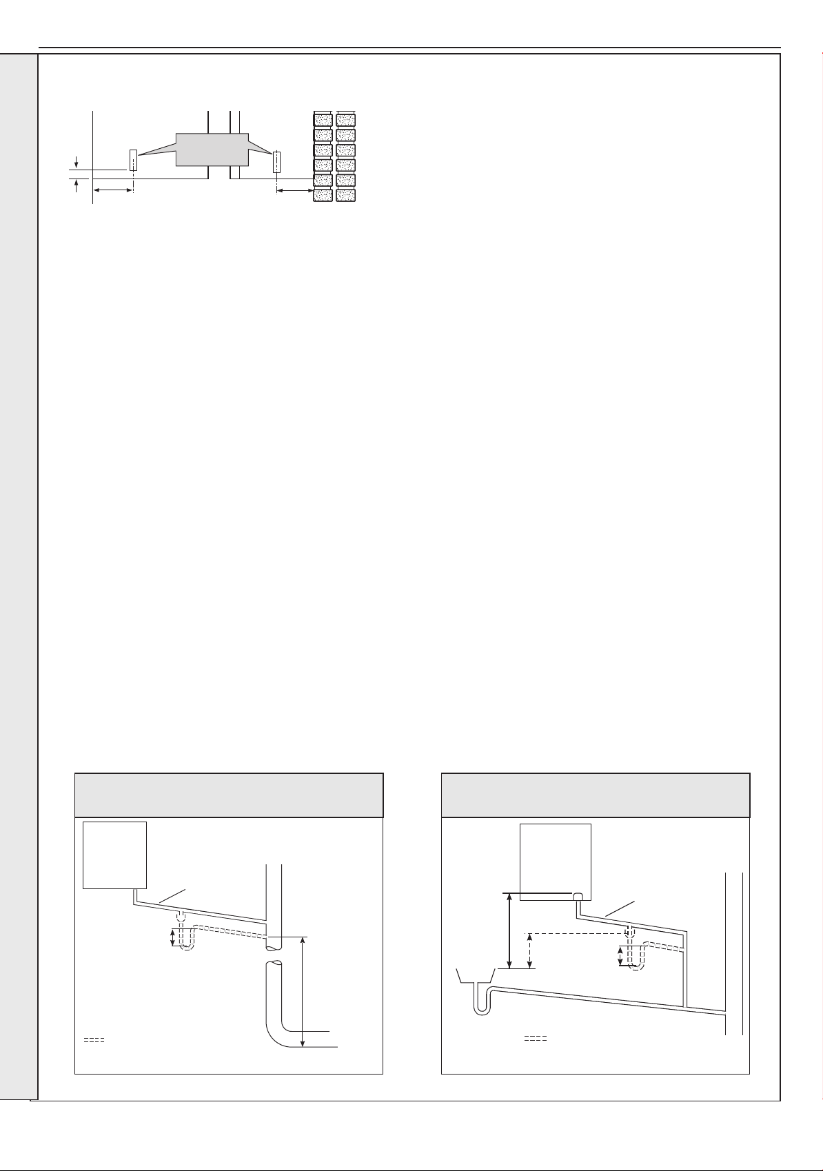
2.12 CONDENSATE DRAIN
This appliance is tted with a siphonic 75mm condensate trap
system that requires lling before operating the appliance for the
1st time or after maintenance.
INSTALLATION
All condensate pipework should conform to the following:
a. Where a new or replacement boiler is being installed, access to
an internal ‘gravity discharge’ termination should be one of the
main factors considered in determining boiler location.
b. Plastic with push t or solvent connections.
c. Internal plastic pipe work a minimum of 19mm ID (typically
22mm OD)
d. External plastic pipe must be a minimum of 30mm ID (typically
32 OD) before it passes through the sleeved wall.
e. All horizontal pipe runs, must fall a minimum of 45mm per metre
away from the Boiler.
f. External & unheated pipe work should be kept to a minimum
and insulated with Class “O” waterproof pipe insulation.
g. All installations must be carried out in accordance to the
relevant connection methods as shown in the “Condensate
installation diagrams” & BS6798.
h. Pipe work must be installed so that it does not allow spillage
into the dwelling in the event of a blockage (through freezing)
i. All internal burrs should be removed from the pipe work and any
ttings.
In order to minimise the risk of freezing during prolonged very cold
spells, one of the following methods of terminating condensate
drainage pipe should be adopted.
Internal Drain Connections
Wherever possible, the condensate drainage pipe should be routed
to drain by gravity to a suitable internal foul water discharge point
such as an internal soil and vent stack or kitchen or bathroom
waste pipe etc. See Figs 1 and 2.
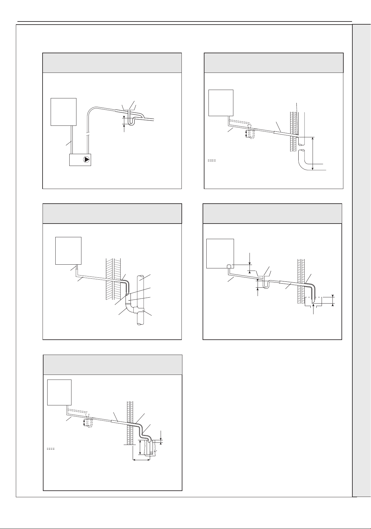
Condensate Pump
Where gravity discharge to an internal termination is not physically
possible or where very long internal pipe runs would be required
to reach a suitable discharge point, a condensate pump of a
specication recommended by the boiler or pump manufacturer
should be used terminating into a suitable internal foul water
discharge point such as an internal soil and vent stack or internal
kitchen or bathroom waste pipe etc. (g 3).
External Drain Connections
The use of an externally run condensate drainage pipe should
only be considered after exhausting all internal termination options
as described previously. An external system must terminate at a
suitable foul water discharge point or purpose designed soak away.
If an external system is chosen then the following measures must
be adopted:
The external pipe run should be kept to a minimum using the most
direct and “most vertical” route possible to the discharge point, with
no horizontal sections in which condensate might collect.
- For connections to an external soil/vent stack see Fig 4.
Insulation measures as described should be used.
- When a rainwater downpipe is used, an air break must be
installed between the condensate drainage pipe and the
downpipe to avoid reverse ow of rainwater into the boiler
should the downpipe become ooded or frozen, see Fig 5.
- Where the condensate drain pipe terminates over an open
foul drain or gully, the pipe should terminate below the grating
level, but above water level, to minimise “wind chill” at the open
end. The use of a drain cover (as used to prevent blockage by
leaves) may offer further prevention from wind chill. See Fig 6.
- Where the condensate drain pipe terminates in a purpose
designed soak away (see BS 6798) any above ground
condensate drain pipe sections should be run and insulated as
described above. See Fig 7
Unheated Internal Areas
Internal condensate drain pipes run in unheated areas, e.g. lofts
basements and garages, should be treated as external pipe.
Ensure the customer is aware of the effects created by a frozen
condensate and is shown where this information can be found in
the user manual.
26
Figure 1 - Connection of Condensate Drainage Pipe to
Internal Soil & Vent Stack
Boiler
with 75mm
sealed
condensate
trap
Boilers without 75mm sealed
condensate trap must be fitted with
a 75mm trap and visible air break
Min Ø 19mm
Internal pipe
75
Soil & vent stack
≥ 450
Figure 2 - Connection of a Condensate Drainage Pipe
Downstream of a Sink, Basin, Bath or Shower Water Trap to
Internal Soil Vent Stack
Minimum
connection
height up to 3
storeys
continued . . . . .
Installation and Servicing
Page 27
≥ 25 Below grate
CONT’D.......
SECTION 2 - INSTALLATION
Figure 3 - Connection of a Condensate Pump Typical
Method (see manufacturers detailed instructions)
Boiler
with 75mm
sealed
condensate
trap
Min Ø 19mm
Internal pipe
Condensate pump
(Install in accordance with manufacturers instructions)
Visible air break
75
Figure 5 - Connection of a Condensate Drainage Pipe to an
External Rainwater Downpipe (only combined foul/rainwater
drain)
Figure 4 - Connection of condensate Drainage Pipe to
External Soil & Vent Stack
Boiler
with 75mm
sealed
condensate
trap
Min Ø 19mm
Internal pipe
Boilers without 75mm sealed
condensate trap must be fitted with
a 75mm trap and visible air break
75
Min Ø 30mm
Internal pipe
Water/weather
proof insulation
Soil & vent stack
Minimum
connection
≥ 450
height up to 3
storeys
Figure 6 - Connection of Condensate Drainage Pipe
Upstream of a Sink, Basin, Bath or Shower Waste Trap to
External Drain, Gulley or Ranwater Hopper
INSTALLATION
Boiler
with 75mm
sealed
condensate
Min Ø 19mm
Internal pipe
Min Ø 30mm
Internal pipe
trap
Terminated
and cut at 45º
43mm 90º male/
female bend
Water/
weather proof
insulation
combined foul/
rain water drain
External air
break
Air gap
68mm Ø PVCU
Strap on fitting
Figure 7 - Connection of a Condensate Drainage Pipe to an
External Purpose Made Soak Away.
Boiler
with 75mm
sealed
condensate
trap
Min Ø 19mm
Internal pipe
75
Min Ø 30mm
Internal pipe
Water/Weather
proof insulation
Max 3m external
pipework
Boiler
with 75mm
sealed
condensate
trap
Min Ø 19mm
Internal pipe
Sink, basin, bath or
shower with integral
overflow and 75mm trap
≥ 100
75
Visible air break
at plug hole
Minimum 30mm
internal pipe
Water/
weather proof
insulation
45º pipe
termination
Installation and Servicing
Boilers without 75mm sealed
condensate trap must be fitted with
a 75mm trap and visible air break
2 rows of three Ø12mm holes
25mm centres, 50mm from
the bottom of the tube, facing
away from the house
≥ 25
≥ 300
≥ 500
Limestone
chippings
27
Page 28
SECTION 2 - INSTALLATION
Yellow
Handle
Black
Handle
Black
Handle
CH Flow
Gas
Supply
CH Return
Safety
Drain
Valve
3G9705
Safety Valve
Drain Connection
15mm elbow
or fittings
(not supplied)
Safety Valve
Drain Pipe
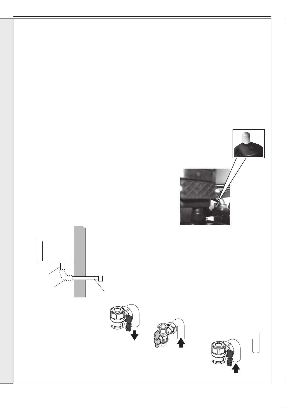
2.13 CONNECTIONS & FILLING
NOTES.
Ensure all boss blanking plugs are removed before connecting hardware. Each valve must be tted to the correct boss as shown
in the picture.
Ensure each union is tted with bre seals provided. Do not subject any of the isolating valves to heat as the seals may
be damaged.
WATER CONNECTIONS CH
1. Connect the CH ow service valve provided in the hardware
pack to the threaded boss connection provided at the lower
rear of the boiler.
2. Connect the CH return valve.
INSTALLATION
GAS CONNECTION
IMPORTANT. The gas service cock is sealed with a non-metallic
blue bre washer, which must not be overheated when making
capillary connections. Refer to Section 1.13 for details of the position
of the gas connection.
For additional gas supply information refer to “Gas Supply” on page 12.
SAFETY VALVE DRAIN
The safety valve connection, located at the bottom right-hand side of the boiler,
comprises a 15mm diameter stub pipe.
The discharge pipe should be positioned so that the discharge of water or
steam cannot create a hazard to the occupants of the premises or damage the
electrical components and wiring.
A purpose made safety valve drain pipe is provided with the boiler to allow
safe discharge through a wall to the outside of the building. This is particularly
relevant to ‘high rise’ installations but can be used for all installations.
FILLING
IMPORTANT - when lling:
A. Ensure the dust cap on air vent
located at the rear of the pump
chamber is slightly unscrewed.
B. When lling, there may be a slight
water leak from the air vent therefore
electrical connections should be
protected.
1. Ensure that the CH isolating
handles are open.
2. Fill and vent the system. Refer to
Section 1.14 for lling and setting
pressure procedure.
3. Check for water
soundness.
Dust Cap
FLUE OUTLET
28
Note that all isolation handles are
shown in the open position.
Installation and Servicing
Page 29
SECTION 2 - INSTALLATION
2.14 ELECTRICAL CONNECTIONS
WARNING. This appliance MUST be earthed.
A mains supply of 230Vac ~ 50 Hz is required.
The fuse rating should be 3A. All external controls and wiring
must be suitable for mains voltage.
Wiring external to the boiler MUST be in accordance with the
current I.E.E. (BS.7671) Wiring Regulations and any local
regulations.
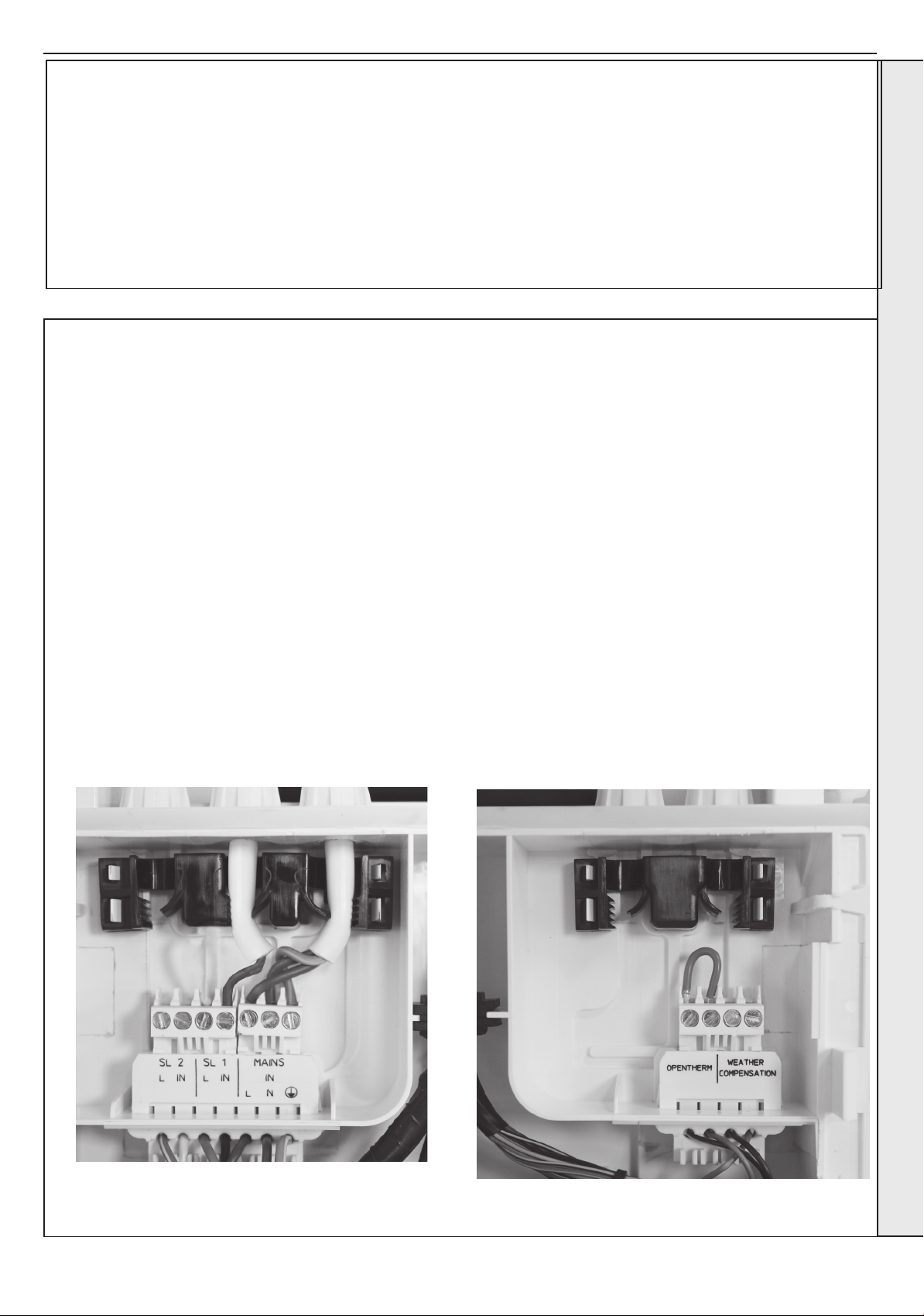
2.15 INSTALLER WIRING
The Keston System S boiler comes pre-tted with 1.8m of
mains cable. This must be connected to a permanent live
supply and NOT switched by thermostats/programmers. If
the supply cord is damaged, it must be replaced by the
manufacturer, service agent or similarly qualied persons in
order to avoid hazard.
Connecting the Switched Live to the Boiler
1. Consult the Plan diagrams overleaf.
2. Isolate the mains supply to the boiler
3. Remove the front panel. Refer to Section 2.19 .
Swing down the control box into the service position, unclip
4.
and swing back the installer wiring cover and latch into the
retaining clips. Refer to Section 3.8.
Wiring should be 3 core PVC insulated cable, not less than
0.75mm2 (24 x 0.2mm), and to BS 6500 Table 16. For IE
reference should be made to the current ETCI rules for
electrical installations.
Connection must be made in a way that allows complete
isolation of the electrical supply such as a double pole switch
having a 3mm (1/8”) contact separation in both poles. The
means of isolation must be accessible to the user after
installation.
All of the connections can now be readily accessed, the plugs can
be removed to aid wiring.
5. Connect the SL1 and SL2 switched lives to the terminal
block as required.
Note the cable strain relief system and grommets. Once any
wiring is completed, to secure the boiler, reverse the order
above.
FROST THERMOSTAT - WIRING
If parts of the system are vulnerable to freezing or the
programmer is likely to be left off during cold weather, a frost
stat should be tted in conjunction with a pipe thermostat.
INSTALLATION
INSTALLER CONNECTIONS (LHS) INSTALLER CONNECTIONS (RHS)
Installation and Servicing
FLUE OUTLET
29
Page 30
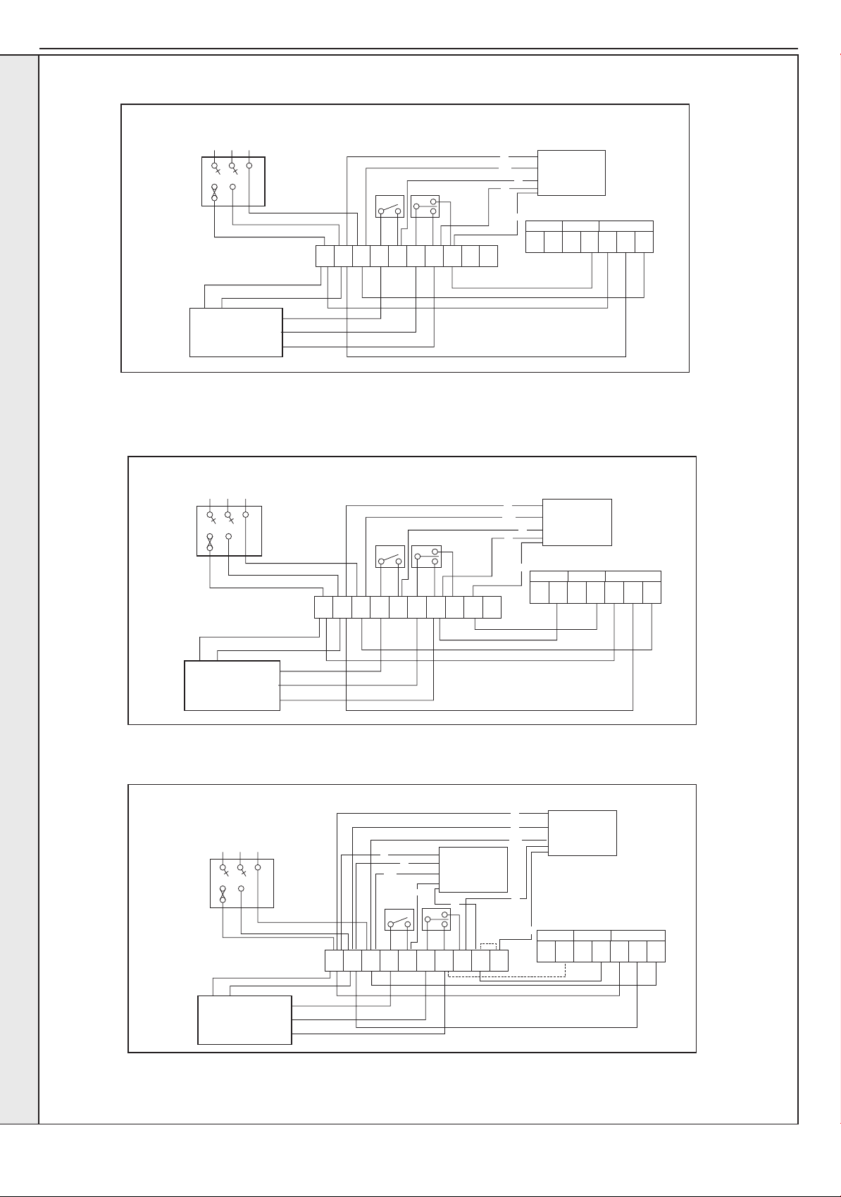
w
g
o
b
g/y
BOILER
L N
MAINS IN
SL 1
E
SL 2
L N E
L N E
CHONR/S
ON
R/S /SC
HWONHW
OFF
C/S
ON
L IN L IN
FUSED
SPUR
TIMER
CH ONL N
HW ON
HW OFF
Y PLAN
VALVE
w
g
o
g/y
b
BOILER
LN
MAINS IN
SL 1SL 2
E
LNE
LNE
CHONR/S
ON
R/SC/S
HWONHW
OFF
C/SONHTG
ON
INLINL
FUSED
SPUR
TIMER
CH ONLN
HW ON
HW OFF
Y PLAN
VALV E
br
br
o
g/y
b
b
g/y
g
g
LN
E
LNE
CHONR/SONHWONHW
OFF
C/S
ON
FUSED
SPUR
TIMER
CH ONLN
HW ON
HW
S PLAN
VALV E
CH
S PLAN
VALV E
R/S
o
BOILER
LN
MAINS IN
SL 1SL 2
EINLINL
L1
L2
HW OFF
C/S
......... INSTALLER WIRING
KESTON SYSTEM S BOILER WITH Y PLAN SYSTEM
INSTALLATION
Note. If an outside sensor is connected, then see diagram below
SECTION 2 - INSTALLATION
KESTON SYSTEM S BOILER WITH Y PLAN SYSTEM & OUTSIDE SENSOR KIT
KESTON SYSTEM S BOILER WITH S PLAN SYSTEM
30
Note. If an outside sensor is connected then;
• Fit Link wire ‘L2’
Installation and Servicing
Page 31
SECTION 2 - INSTALLATION
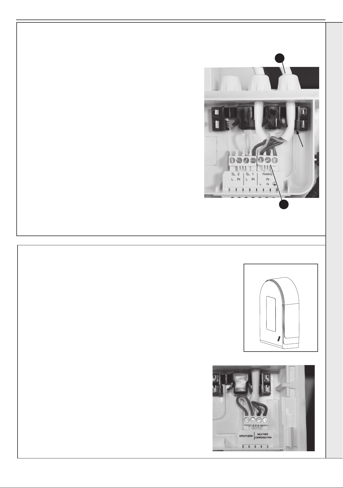
2.16 REPLACING PRE-FITTED MAINS CABLE
If it is necessary to use an alternative mains cable to the one pre-tted
then use the following guide.
Replacement wiring should comply with notes in Section 2.18 and be
caried out by a qualied person to avoid a hazard.
1. Isolate the mains supply to the boiler.
2. Remove the front panel. Refer to Section 3.2.
Swing the control box down into the service position, unclip and swing
3.
back the installer wiring cover to latch into the retaining clips. Refer to
Section 3.8.
4. Unplug the mains connector and release the cable from strain relief.
5. Unscrew the L N & E connections & remove wires from connector.
6. Remove the mains cable by pulling back through the grommet .
7. Route the replacement cable through the grommet and re-t in
reverse order.
8. Close the installer wiring cover ensuring that it is located correctly and
that the cable is retained into the strain relief as shown.
9. Swing the control box back up into the operating position and re-t
the front panel ensuring a good seal is made.
NOTE. When making the mains electrical connections to the boiler it
is important that the wires are prepared in such a way that the earth
conductor is longer than the current carrying conductors, such that if the
cord anchorage should slip, the current carrying conductors become taut
before the earthing conductor.
6
INSTALLATION
Strain Relief
4
2.17 FITTING THE WEATHER COMPENSATION KIT
This kit provides the facility to apply outside air temperature control to the boiler water
ow temperature which provides energy savings. The outside sensor provided measures
outside air temperature and sends a signal to the boiler, which adjusts the maximum boiler
ow temperature in response. If outside air temperature is greater than the system design
temperature, the boiler ow temperature is reduced providing running cost savings. The boiler
will operate in the condensing mode more frequently increasing savings.
Once the sensor is tted it is automatically detected.
The sensor operation may be congured by adjustment of the boiler operating parameters, if
necessary.
- SUPPLIED AS STANDARD
FITTING THE KIT
Fitting the sensor
The air sensor should be located on an external wall of the building
to be heated. Fix the sensor to a north/north-east facing wall to avoid
direct radiation from the sun. The air sensor should be located to
avoid any heating effect from the boiler ue.
To x the air sensor to the wall, unscrew the sensor box plastic cover
and screw/plug the sensor body to the wall.
2
Wire a twin core 0.5mm
an RH grommet located on the underside of the control box. Cable
length between sensor and boiler should be no greater than 20m.
Note that this connection is protected extra low voltage. It is not
necessary for the person carrying out the wiring to be approved to
Part P of the Building Regulations.
Avoid running this cable alongside mains voltage cables.
cable from the sensor to the boiler through
Outside Air Sensor
Installation and Servicing
31
Page 32
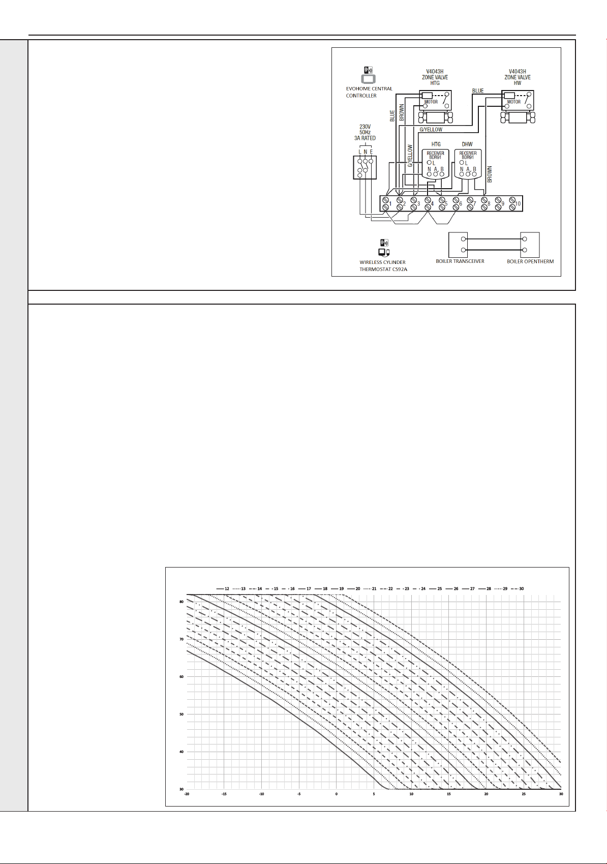
SECTION 2 - INSTALLATION
2.18 EXTERNAL ELECTRICAL CONTROLS
Wiring External to the Boiler
The fuse rating should be 3A.
Wiring external to the boiler MUST be in accordance with the current
I.E.E. (BS.7671) Wiring Regulations and any local regulations.
Frost Protection
If parts of the pipework run outside the house or if the boiler will be left
off for more than a day or so then a frost thermostat should be wired
into the system.
The frost thermostat should be sited in a cold place but where it can
sense heat from the system.
Note. If the boiler is installed in a garage it may be necessary to t a
INSTALLATION
pipe thermostat, preferably on the return pipework.
EXAMPLE - Connection to Honeywell Evohome
(for additional information visit www.honeywelluk.com)
2.19 FITTING THE WEATHER COMPENSATION KIT - SUPPLIED AS STANDARD
CH OPERATION
The On and Off time control of central heating should be
controlled by a separate timer, connected to SL1 of the boiler.
During programmed On times the Central Heating Radiator
Flow Temperature is controlled by the boiler relative to the
Outside Temperature as shown in the diagram.
The Room temperature can be adjusted using the Central
Heating Temperature Control Knob on the boiler as follows.
Essentially rotating the knob clockwise increases the room
temperature and rotating the knob anti-clockwise decreases the
room temperature.
The Room Temperature Setpoint in the associated graph is
not directly related to the Actual Room Temperature but is the
Desirable Room Temperature during a programmed CH period.
This can be adjusted between 5 and 30 degrees by the
CH Potentiometer Knob on the Boiler when the Outside
Temperature Sensor is connected. The graph only shows
temperatures between 12 and 30 degrees for clarity.
Examples:
1. If the CH Potentiometer
Knob is set to display
22ºC on the Boiler
Display the Room
Temperature Setpoint will
be 22ºC and the curve 22
will be followed, indicated
by 11th curve in from
the left hand side. So as
the outside temperature
varies the Flow Setpoint
to the CH circuit will
increase and decrease
proportionally.
FLOW SETPOINT
2. If the CH Potentiometer Knob is rotated fully clockwise, the
Boiler Display will read 30ºC and the Room Temperature
Setpoint will be 30ºC hence the curve 30 will be followed.
3. If the CH Potentiometer Knob is rotated fully anticlockwise,
the Boiler Display will read 5ºC and the Room Temperature
Setpoint will be 5ºC. This is an unrealistic Room
Temperature Setpoint for a CH period during an ON time,
but it is calculated internally for managing Frost Protection
for the system based upon Outside Temperature.
DHW OPERATION
When the system is in a timed on period for DHW and the tank
stat is not satised, a call for heat will be generated on the
switched live input SL2 of the boiler.
This will ensure that Weather Compensation adjustment is
ignored at this time. The set point will be xed at 70 degrees.
The demand is indicated on the display by a ‘d’ and the burner
on symbol as appropriate.
ROOM TEMPERATURE SETPOINT
32
OUTSIDE TEMPERATURE
Installation and Servicing
Page 33
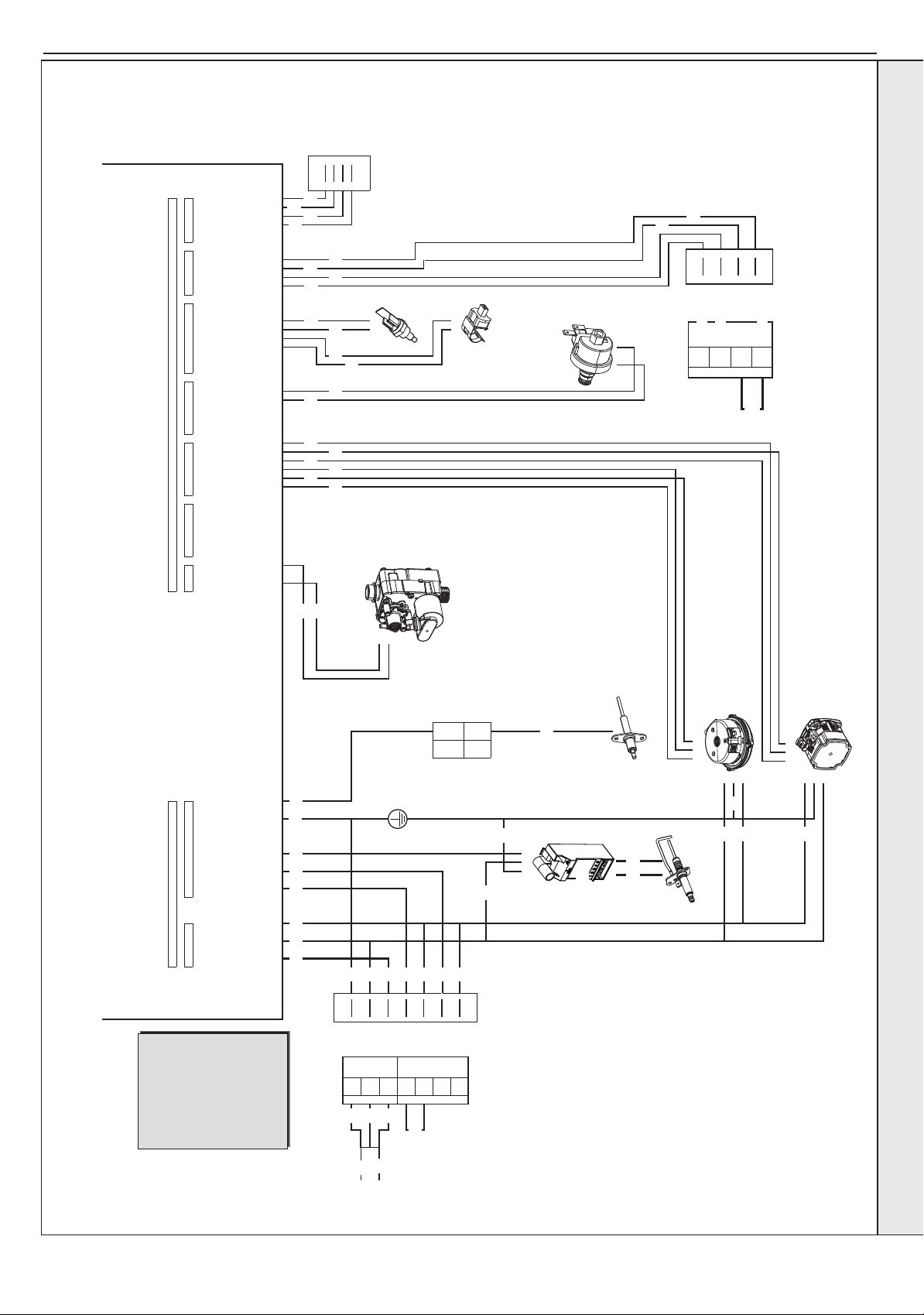
2.20 WIRING DIAGRAM
3 2 1 6 5 4 3 2 1 3 2 1 6 5 4 3 2 1 6 5 4 3 2 1 6 5 4 3 2 1 8 7 6 5 4 3 2 1 5 4 3 2 1 5 4 3 2 1
SERVICE
CONNECTOR
234
1 PE 1 5
2 N 2
1 2
3 L 3
1
Chassis
Earth
SL 1 - IN 4
2 5SL 1 - L
SL 2 - IN
SL 2 - L
3 6
1 2
4 7
1
2
3
4
2 3 4
123
3 2 1
123
PELV
X4
230V 50Hz Mains
NO. 2 B2 24V
NO. 5 A2 24V
NO. 6 B1
NO. 4 B3
NO. 3 A3
NO. 1 A1
X6
WPS 5V
X5
FLOW +
FAN FEEDBACK
FAN PWM
FAN GND
PUMP FEEDBACK
PUMP PWM
NC
GAS VALVE -
GAS VALVE +
TURBINE SIGNAL
TURBINE GND
X1
TURBINE 5V
CH LIVE
IGNITION LIVE
PE
X2
PUMP LIVE
DHW LIVE
X3
PUMP GND
X9X8
OWC +
OWC -
OPENTHERM +
OPENTHERM -
OPENTHERM 5V
CHIP COM BUS TX
CHIP COM BUS 24V
CHIP COM BUS GND
CHIP COM BUS 5V
CHIP COM BUS RX
M
AINS LIVE
MAINS NEUTRAL
AUXILIARY LIVE
IONISATION
2
2
FLOW -
DHW +
DHW -
X7
1
3 2 1
1
2
WPS SIGNAL
WPS GND
FLUE +
FLUE -
RETURN +
RETURN -
1
black
grey
red
green
blue
brown
green/yellow
orange
pink
violet
yellow
-----------
bk
gy
r
g
b
br
g/y
o
p
v
y
KEY
1
2
3
4
WEATHER
COMPENSATION
OPEN
THERM
DETECTION
ELECTRODE
FAN
PUMP
RETURN
THERM
FLOW
THERM
GAS
VALV E
SPARK
GENERATOR
IGNITION
ELECTRODE
WATER
PRESSURE
SWITCH
bk
bk
br
b
g/y g/y
g/y
g/y
g/y
b
r
r
bk
bk
bk
b
g/y
b
b
br
r
r bk bkw brbbr
bk
r
w
r
p
bk
y
y p
bk
p
r
bk bk bk
bk
bk
v
v
r
y
g
bk
gy
v
or
bk
SECTION 2 - INSTALLATION
INSTALLATION
Installation and Servicing
33
Page 34
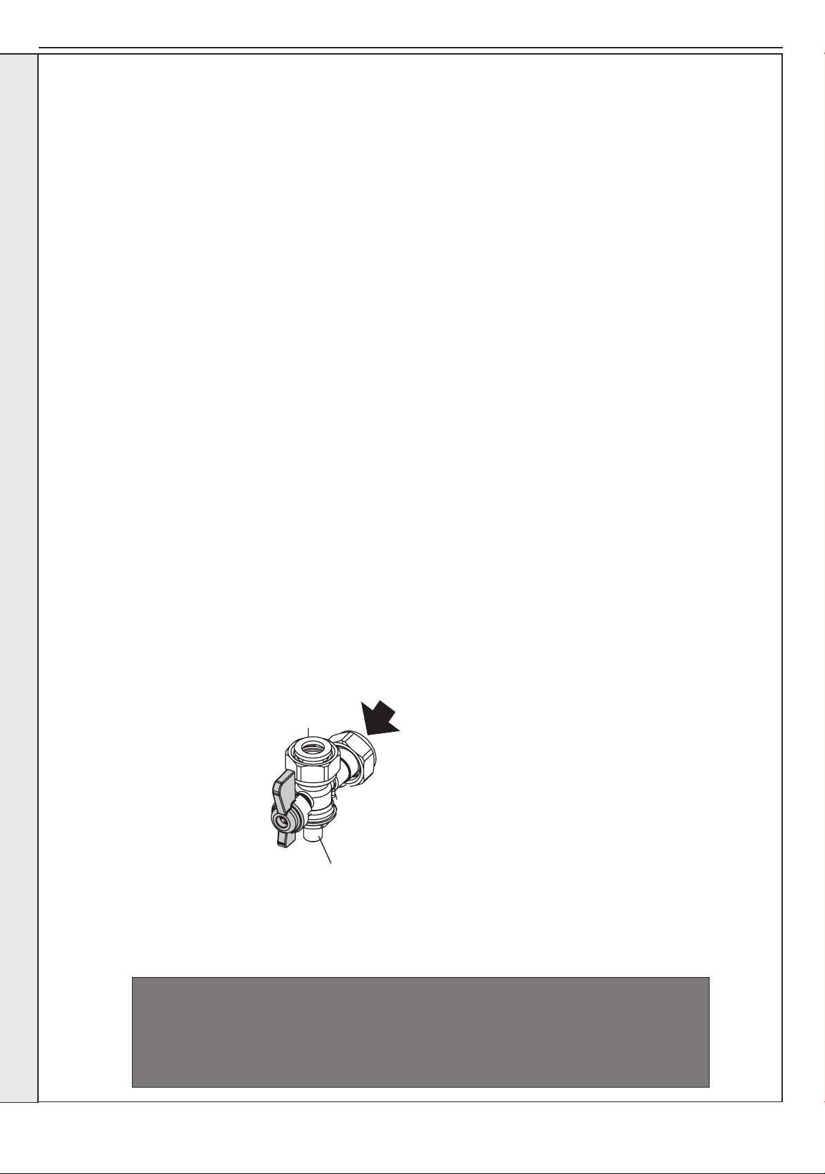
SECTION 2 - INSTALLATION
Gas
Supply
Gas Pressure
Test Point
2.21
INSTALLATION
COMMISSIONING AND TESTING
A. Electrical Installation
1. Checks to ensure electrical safety should be carried out by a
competent person.
2. ALWAYS carry out the preliminary electrical system checks,
i.e. earth continuity, polarity, resistance to earth and short
circuit, using a suitable test meter.
3. After wiring the boiler, all grommets in the bottom panel
MUST be in place to ensure that the boiler case sealing is
maintained.
WARNING. Whilst effecting the required gas tightness test and purging air from the gas installation,
open all windows and doors, extinguish naked lights and DO NOT SMOKE.
GENERAL
Please Note: The combustion for this appliance has
been checked, adjusted and preset at the factory for
operation on the gas type dened on the appliance
data plate. DO NOT adjust the air/gas ratio valve.
Having checked:
- That the boiler has been installed in accordance
with these instructions.
- The integrity of the ue system and the ue seals,
as described in the Flue Installation section.
Proceed to put the boiler into operation as follows:
B. Gas Installation
1. The whole of the gas installation, including the meter,
should be inspected and tested for tightness and purged in
accordance with the recommendations of BS. 6891.
In IE refer to IS.813.
2. Purge air from the gas installation by the approved methods
only.
CHECK THE OPERATIONAL (WORKING) GAS
INLET PRESSURE
Set up the boiler to operate at maximum rate.
With the boiler operating in the maximum rate
condition check that the
operational (working) gas
pressure at the inlet gas pressure
test point complies with the
requirements - refer to “Gas
Supply” on page 12.
Ensure that this inlet pressure
can be obtained with all other
gas appliances in the property
working.
As part of the commissioning process, the combustion of this appliance must be checked
and the Benchmark Checklist completed. A ow chart to assist is provided on page 63.
34
ATTENTION !
IT IS A CONDITION OF THE MANUFACTURERS WARRANTY THAT THE
BENCHMARK COMMISSIONING CHECKLIST IS FULLY COMPLETED
AND LEFT WITH THE APPLIANCE
Installation and Servicing
Page 35
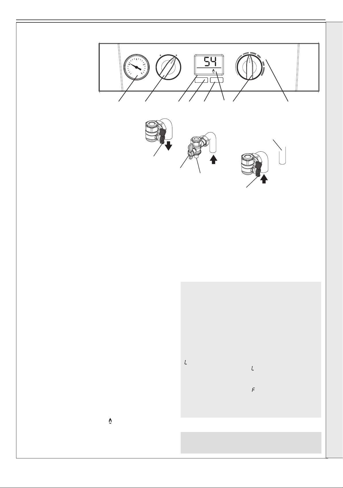
ºC
ON
e
MIN
MAX
RESTART
BOILER BOILER
OFF ON
2.22 INITIAL LIGHTING
CH Flow
SupplyGas
CH Return
Safety
Drain
Valve
F
J
L
H
K
Legend
A. Central Heating Temperature Knob
B. Mode Knob
C. Boiler Status
D. Burner ‘on’ indicator
E. Central Heating Economy Setting
F. CH Flow Isolating Valve
G. System Pressure Gauge
H. Gas Inlet Pressure Test Point
J. Gas Service Cock
K. CH Return Isolating Valve
L. Drain Valve
M. Function Button
N. Restart Button
SECTION 2 - INSTALLATION
G B C M N AD E
INSTALLATION
Note. Valves shown are in the open position.
1. Check that the system has been lled and that the boiler is not
airlocked. Ensure the automatic air vent cap is open. Refer to
Section 2.16.
Note.
It is important the burner is not operated before the system is fully
vented of air. If it is necessary to operate the appliance pump to
assist venting of the air this must be done with the gas service cock
turned off.
2. Ret the boiler front panel. Refer to Section 3.2.
3. Check that the drain valve (L) is closed and that the CH isolating
valve (F and K) are OPEN.
4. Check that the electrical supply is OFF.
5. Check that the boiler mode control knob (B) is OFF.
6. Check that the gas service cock (J) is OPEN.
7. Slacken the screw in the inlet pressure test point (H) and connect
a gas pressure gauge via a exible tube.
8. Switch the electricity supply ON and check all external controls
are calling for heat.
CENTRAL HEATING
9. Set the CH temp control (A) to “MAX” and turn the mode knob
(B) to “BOILER ON”. The boiler control should now go through
its ignition sequence until the burner is established.
10. If the boiler does not light after 5 attempts the boiler will lock out
and display fault code L 2 .
Restart the boiler (Refer to Section 2.24). The boiler will repeat
its ignition sequence. If restart occurs 5 times within 15 minutes
then LC will be shown.
If power is removed this will be reset.
IMPORTANT
The gas input to the burner is regulated by the gas
valve according to the air ow produced by the fan.
It is NOT user-adjustable. Any interference to sealed
settings on the gas valve will adversely affect operation
and render our warranty void.
For additional gas supply information refer to “Gas Supply”
on page 12.
THE DISPLAY
The user control has one display to inform the user about
the status of the boiler. The LCD Display shows the status
of the ame. If no ame is detected the ame symbol
will not be visible. When the ame is detected the ame
symbol will be visible permanently.
Below is a list with display function in normal operation.
00
Standby, no demand for heat present.
ON
There is a demand for heat.
FP
Boiler is active for boiler frost protection.
Boiler is in lockout for a specic error. Display will
show a number after the “ ” to indicate which error is
detected.
F Boiler has a fault for a specic error. Display will
show a number after the “
detected.
Note: Boiler frost protection - boiler operates if the
ambient temperature is below 5ºC until it reaches 19ºC.
” to indicate which error is
When the burner is established the ‘
with the ‘ON’ indicating central heating operation and the current
ow temperature shown in the 2 digit display.
11. Ensure that with the boiler operating the dynamic gas pressure
is able to obtain maximum output. Refer to Table 2.
Installation and Servicing
’ will be shown on the display
Note. The boiler incorporates a fan overrun cycle which
MUST NOT be prematurely interrupted by isolation of the
mains electricity supply.
35
Page 36
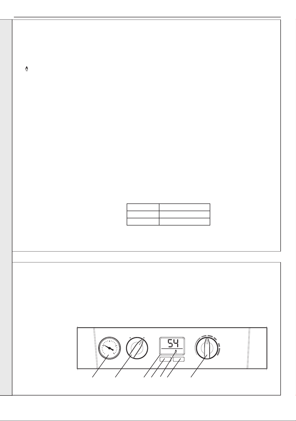
SECTION 2 - INSTALLATION
ºC
ON
e
MIN
MAX
RESTART
BOILER BOILER
OFF ON
G B C E D F A
2.23 GENERAL CHECKS
Make the following checks for correct operation:
CENTRAL HEATING (CH) MODE
1. Ensure that the CH external controls are
calling for heat.
The display should show:
‘
’ ‘ON’
2. Gas Rate
Check the boiler gas rate when the boiler is
at maximum output.
Check at the gas meter, with no other
appliance in use.
Refer to Table 2 for gas rates.
INSTALLATION
3. Set the central heating external controls
to OFF. The burner should go off and the
pump continue to run for two minutes.
The display should read:
00
4. Check the correct operation of the timer
(if tted) and all other system controls.
Operate each control separately and check
that the main burner responds.
WATER CIRCULATION SYSTEM
1. With the system COLD, check that the initial pressure is correct to the
system design requirements.
For pre-pressurised systems, this should be 1.0 bar.
With the system HOT, examine all water connections for soundness. The
2.
system pressure will increase with temperature rise but should not exceed 2.5
bar.
3. With the system still hot, turn off the gas, water and electricity supplies to
the boiler and drain down to complete the ushing process.
Note: A ushing solution should be used during the ushing procedure.
Flushing solutions: Fernox Superoc, Sentinel X300 (new systems) or
X400 (existing systems). Refer to Section 1.16.
4. Rell and vent the system, add inhibitor (see Section 1.16), clear all air
locks and again check for water soundness.
5. Reset the system initial pressure to the design requirement.
6. Balance the system. Refer to Section 1.15.
Check the condensate drain for leaks and check that it is discharging correctly.
7.
8. Finally, set the controls to the User’s requirements.
Note: The pump will operate briey as a self-check once every 24 hours in
the absence of any system demand.
WATER TEMPERATURES
Temperatures can be selected using the
CH temperature control (A)
2.24 RESTART PROCEDURE
Legend
A. CH temperature control
B. Mode Control Knob
C. Boiler Status
D. Burner ‘on’ indicator
E. Function Button
F. Restart Button
G. Pressure Gauge
Knob Setting CH Flow Temp ºC
Max 80
Min 30
To restart boiler, press the RESTART button (F)
36
Installation and Servicing
Page 37
SECTION 2 - INSTALLATION
2.25 ACCESSING THE INSTALLER MODE
To access Installer Mode press the function button and “RESTART”
Buttons together for more than 5s.
1. The last 3 faults will be shown
See Section 4.1 for Fault Code descriptions
2. “SL” will be shown
To run the burner at minimum rate press “RESTART”, otherwise
press the function button.
3. “SH” will be shown
To run the burner at maximum rate press “RESTART”, otherwise
press the function button.
4. “VF” will be shown
To activate the venting function press “RESTART”, otherwise press
the function button.
The venting function runs for 5 minutes before automatically
returning to normal operation
The Pump alternates between being on for 50s and then off for 10s
2.26 HANDING OVER
5. “dU” will be shown
press the Function button
6. “P1” will be shown
To set the minimum CH pump speed to 100% press “RESTART”,
otherwise press the function button.
7. “P7” will be shown
To set the minimum CH pump speed to 70% (default) press
“RESTART”, otherwise press the function button to Exit.
INSTALLATION
After completing installation and commissioning of the system the installer should hand over to the householder by the following actions:
1. Hand the User Instructions to the householder and explain his/
her responsibilities under the relevant national regulations.
2. Explain and demonstrate lighting and shut down procedures.
3. The operation of the boiler and the use and adjustment of all
system controls should be fully explained to the householder,
to ensure the greatest possible fuel economy consistent with
the household requirements of both heating and hot water
consumption.
Advise the User of the precautions necessary to prevent
damage to the system and the building, in the event of the
system remaining inoperative during frosty conditions.
4. Explain the function and the use of the boiler heating controls.
10. After installation and commissioning please complete the
Benchmark Commissioning Checklist before handover to the
customer. For IE, its is necessary to complete a “Declaration of
Conformity” to indicate compliance to I.S. 813:2002.
IMPORTANT
11. A comprehensive service should be carried out ANNUALLY.
Stress the importance of regular servicing by a Gas Safe
Registered Engineer. In IE servicing work must be carried out
by a Registered Gas Installer (RGII).
12. Inform the householder of the guarantee/registration found
within the envelope pack and the requirement to register it to
receive the full benet of the warranty.
5. Explain the function of the boiler fault mode.
Emphasise that if a fault is indicated refer to “Fault Codes” in
the User Guide.
6. Explain and demonstrate the function of time and temperature
controls, radiator valves etc., for economic use of the system.
7. If a timer is tted draw attention to the timer Users Instructions
and hand them to the householder.
8. Loss of system water pressure
Explain that the dial on the boiler indicates the central heating
system pressure and that if the normal COLD pressure of the
system is seen to decrease over a period of time then a water
leak is indicated. Explain the re-pressurising procedure and if
unable to re-pressurise or if the pressure continues to drop a
registered local heating installer should be consulted.
9. Explain Boiler restart procedure.
Installation and Servicing
37
Page 38
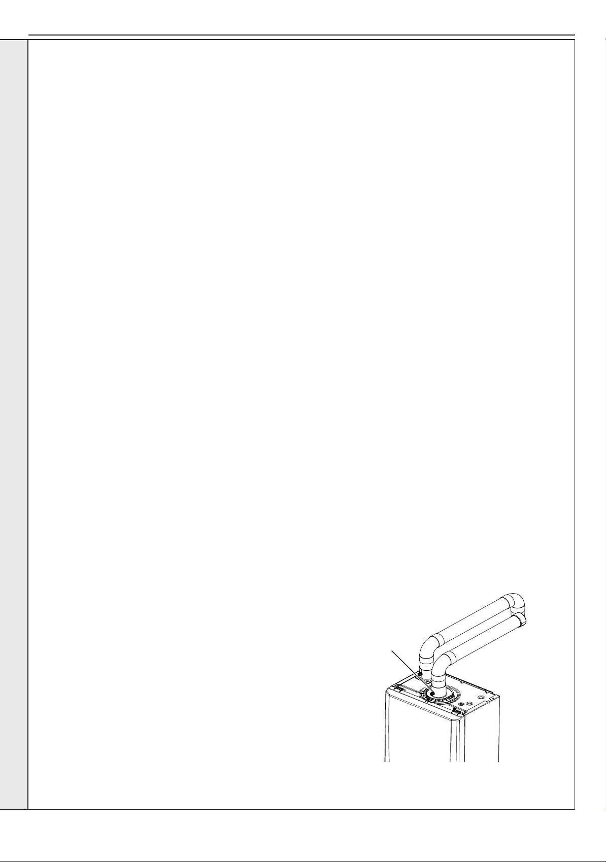
SECTION 3 - SERVICING
3.1 SERVICING SCHEDULE
For the very latest copy of literature for specication & maintenance practices, visit our website www.keston.co.uk, where you will
be able to download the relevant information. .
WARNING. Always turn OFF the gas supply at the gas service cock, and switch OFF and disconnect the electricity
supply to the appliance before servicing.
Combustion testing must be carried out by a competent person using a combustion analyser conforming to BS7927.
To ensure the continued safe and efcient operation of the appliance it is recommended that it is checked at regular intervals and
serviced as necessary. The frequency of servicing will depend upon the installation condition and usage but should be carried out
at least annually.
It is the law that any service work must be carried out by a Gas Safe Registered Engineer. In IE service work must be carried out
by a Registered Gas Installer (RGII).
Note. In order to carry out either servicing or replacement of components
the boiler front panel must be removed. Refer to Section 3.2.
PRELIMINARY INSPECTION
1. Light the boiler and carry out a pre-service check, noting any
operational faults (refer to appropriate fault nding chart as
necessary).
2. Check the ue terminal (and terminal guard if tted) is undamaged
and clear of any obstruction.
3. Check combustion by connecting the ue gas analyser to the ue
gas sampling point as shown in the diagram and measure CO and
CO
2 at maximum rate. Repeat at minimum rate.
If the CO / CO
“Cleaning Procedure”.
If the CO / CO
“Check Procedure”.
2 ratio is greater than 0.004 please proceed to
2 ratio is less than 0.004 please proceed to
CHECK PROCEDURE
1. Check all water and gas joints for signs of leakage. Remake any
suspect joints ensuring a gas tightness check is carried out if
applicable and the water system is correctly relled, vented and
re-pressurised.
SERVICING
2. Proceed to “IMPORTANT”.
CLEANING PROCEDURE
1. Clean the main burner. Refer to Section 3.4.
2. Clean the heat exchanger & condensate trap/siphon. Refer to
Section 3.5 & 3.6.
3.
Check the main injector for blockage or damage. Refer to Section 3.3.
4. The cleaning procedures are covered more fully in Sections 3.3 -
3.7 and MUST be carried out in sequence.
5. Proceed to “IMPORTANT”.
Do not operate the boiler if the front panel is not tted.
IMPORTANT
1. If, for any reason, the condensate trap/siphon has been removed,
ensure the trap is relled with water before re-assembling.
GENERAL
Please Note: During routine servicing, and after any
maintenance or change of part of the combustion circuit,
the following must be checked:
- The integrity of the ue system and the ue seals,
- The integrity of the boiler combustion circuit and the
relevant seals
- The operational (working) gas inlet pressure at
maximum rate.
- The gas rate
- The combustion performance.
COMPETENCE TO CARRY OUT THE CHECK OF
COMBUSTION PERFORMANCE
Please Note: BS 6798 Specication for installation
and maintenance of gas-red boilers of rated input not
exceeding 70kW net advises that:
- The person carrying out a combustion measurement
should have been assessed as competent in the use
of a ue gas analyser and the interpretation of the
results.
- The ue gas analyser used should be one meeting
the requirements of BS7927 or BS-EN50379-3
and be calibrated in accordance with the analyser
manufacturers requirements, and
- Competence can be demonstrated by satisfactory
completion of the CPA1 ACS assessment, which
covers the use of electronic portable combustion gas
analysers in accordance with BS7967, Parts 1 to 4.
Flue
sampling
point
2. After completing the servicing or exchange of components always
test for gas tightness.
3. When work is complete the front panel MUST be correctly retted,
ensuring that a good seal is made.
4. Complete the service section in the Benchmark Commissioning
Checklist.
38
Installation and Servicing
Page 39
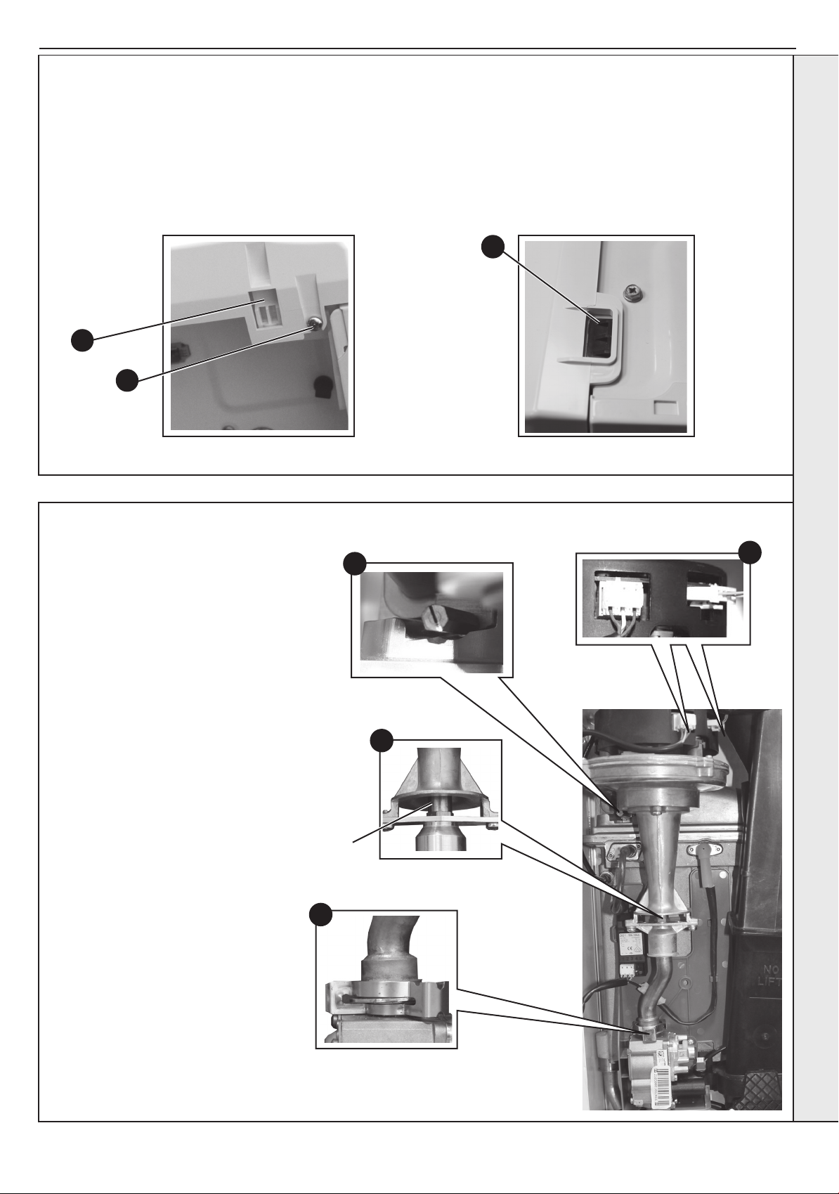
SECTION 3 - SERVICING
3.2 BOILER FRONT PANEL REMOVAL / REPLACEMENT
REMOVAL
1. Loosen the two screws retaining the front panel.
2. Pull the two clips down to disengage and pull panel forward
and upward and remove.
2
1
view from bottom of boiler
REPLACEMENT
3. Hook the panel onto the top retaining clips.
4. Push the panel until the 2 bottom spring clips engage
ensuring the 4 control knobs line up with the holes in the
front panel.
5. Re-tighten the two retaining screws.
3
view from top of boiler
3.3 FAN AND VENTURI ASSEMBLY REMOVAL AND CLEANING
1. Disconnect the electrical leads from the fan.
2. Remove the clip from the gas control valve
outlet and ease the pipe upwards rotate and
then ease down to remove.
3. Remove the extended nut on the fan
mounting bracket.
4. Lift off fan and venturi assembly.
5. Undo the two M4 screws and release the
nozzle assembly.
6. Inspect the injector for blockage or damage.
7. Inspect fan outlet sealing gasket and replace
if necessary.
Injector
3
5
2
1
SERVICING
Installation and Servicing
39
Page 40
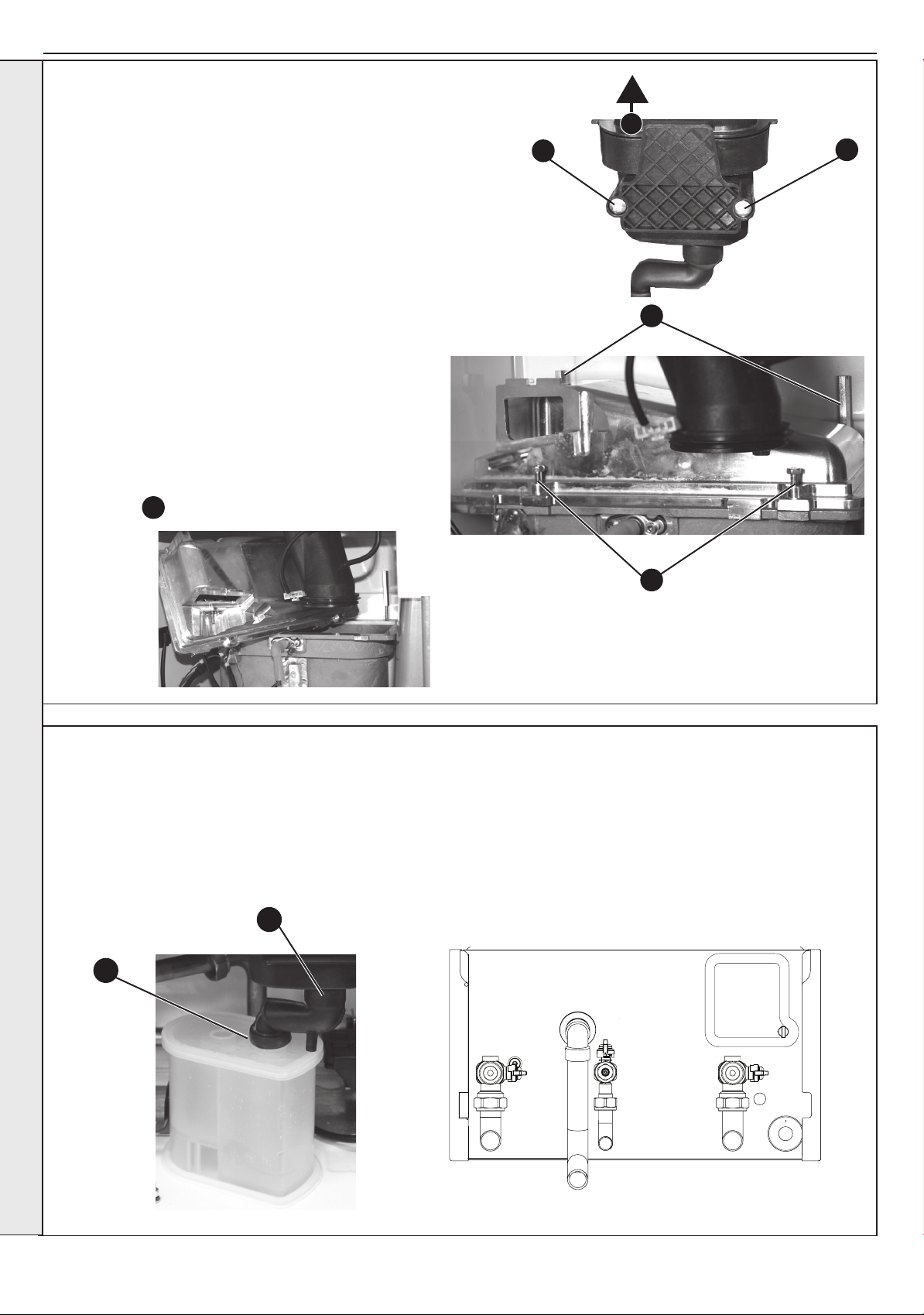
SECTION 3 - SERVICING
3.4 BURNER REMOVAL AND CLEANING
1. Ensure the sump is fully drained. Refer to Section 3.17.
2. Undo the two screws and remove the sump cover retaining the lower
ue manifold.
3. Lift the manifold to clear the bottom sealing gasket and remove
manifold.
4. Remove the 2 burner front xing screws and loosen the 2 rear
extended nuts by at least ten turns.
5. Lift off the burner from the combustion chamber. To facilitate the
removal angle the burner as shown.
IMPORTANT
The burner head is a ceramic plaque construction. Care must be
taken to ensure that the burner is not placed down upon
its face as this may cause damage to the ceramic.
6. Brush off any deposits that may be on the ceramic with a
SOFT brush.
7. Inspect the sealing gasket around the burner for any
signs of damage. Replace as necessary.
5
3
2
4
2
SERVICING
3.5 CLEANING THE CONDENSATE TRAP/SIPHON
1. Pull off the rubber pipe at the sump drain.
2. Disconnect the condensate drain pipe.
3. Turn the siphon clockwise to disengage and lift to
remove.
Note. Keep siphon upright when removing
1
3
4
4. Clean siphon with water.
5. Re-assemble in reverse order.
6. When re-assembling ensure the trap is full of water.
40
Installation and Servicing
Page 41
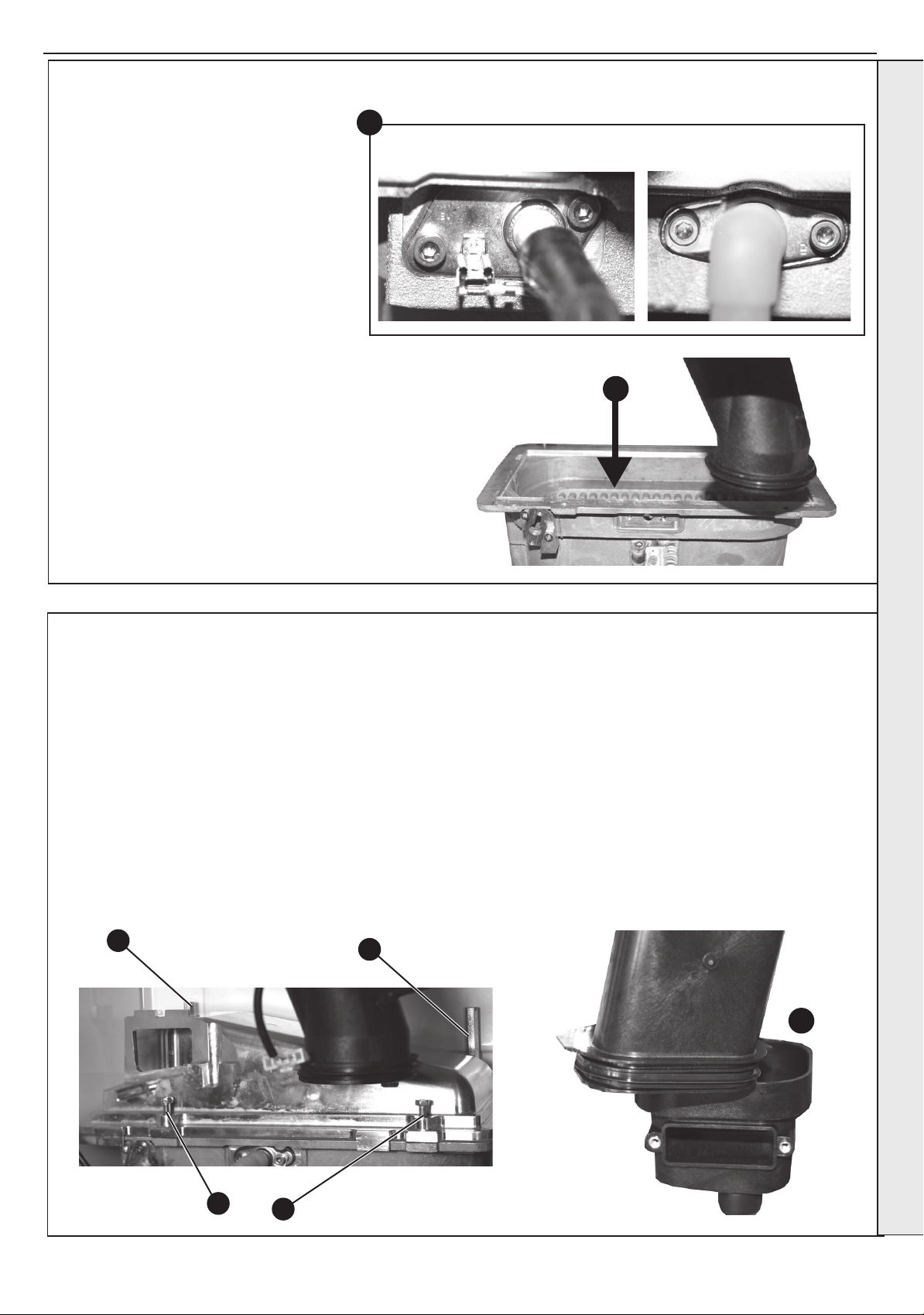
SECTION 3 - SERVICING
3.6 CLEANING THE HEAT EXCHANGER
Note: Ensure the condensate trap/siphon
is fully drained before cleaning. Refer to
Section 3.17.
1. Remove ignition and ame detection
electrodes. Refer to Sections 3.13 & 3.14.
2. It is advisable to replace the sump cover
prior to the water ush process.
3. Thoroughly ush the heat exchanger
by pouring water into the top of the
combustion chamber ensuring the full top
area is covered.
4. Remove the sump cover and clean loose
deposits from the sump.
5. Inspect the ignition and detection
electrodes. Ensure that they are clean
and in good condition - replace if
necessary.
6. Re-t the ignition and ame detection
electrodes, ensuring that both earth tabs
are tted to ignition electrode.
7. Check that the ignition and detection gaps
are correct. Refer to Sections 3.13 & 3.14.
1
Ignition Electrode
Flame Detection
3
3.7 REASSEMBLY
Reassemble the boiler in the following order:
1. Ensure that the condensate trap/siphon is full of water.
2. Ret the burner ensuring the sealing gasket is correctly
positioned and free from damage (tighten the 4 xing screws
in the sequence shown below).
3. Ret the fan / venturi assembly ensuring the retaining tabs
are correctly positioned and the sealing gasket is correctly
positioned and free from damage.
4. Reconnect the fan electrical leads.
5. Remove the sump cover and ret the lower ue manifold as
shown.
6. Ret the sump cover.
4
2
SERVICING
7. Ret the boiler front panel.
IMPORTANT. Ensure that the boiler front panel is
correctly tted and that a good seal is made.
8. Swing the control box back into its working position and
secure.
9. Turn on the gas supply at the gas service cock.
10. Reconnect the electrical supply.
11. Check the operation of the boiler. refer to Sections 2.22
& 2.23.
5
Installation and Servicing
1
3
41
Page 42
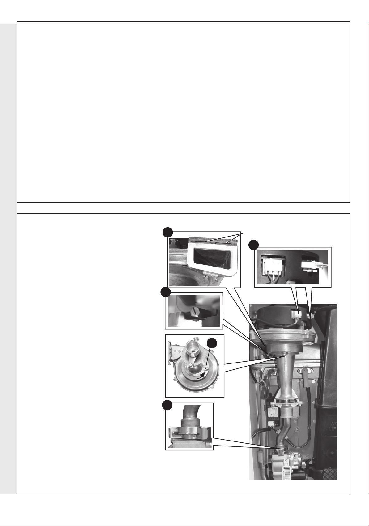
SECTION 3 - SERVICING
3.8 REPLACEMENT OF COMPONENTS
GENERAL
When replacing ANY component
1. Isolate the electricity supply.
2. Turn off the gas supply.
3. Remove the boiler front panel. Refer to Section 3.2.
4. Swing the control box down into its servicing position.
After replacing ANY component check operation of the boiler,
including gas soundness, gas rate and combustion test.
THE BOILER MUST NOT BE OPERATED WITHOUT THE FRONT PANEL FITTED
3.9 FAN REPLACEMENT
IMPORTANT.
When work is complete, the front panel must be correctly
retted - ensuring that a good seal is made.
Notes.
1. In order to assist fault nding, the control panel has
an LCD diagnostic display. The key to boiler fault
conditions is shown in Section 4.
2. In order to replace components in Sections 3.20 - 3.27 it
is necessary to drain the boiler. Refer to Section 3.19.
8
Retaining Tabs
1. Refer to Section 3.8.
2. Disconnect the electrical leads from the fan.
SERVICING
3. Remove the clip from the gas control valve
outlet.
4. Remove the extended nut retaining the fan
mounting bracket.
5. Lift and remove the fan and venturi assembly.
6. Remove the screw and twist venturi anti-
clockwise to remove venturi assembly, noting
the orientation of the venturi in relation to the
fan body.
7. Transfer the venturi assembly to the new fan,
replacing the ‘o’ ring if evidence of damage or
deterioration is visible.
8. Fit the new fan / venturi assembly ensuring the
retaining tabs are correctly positioned and the
fan outlet sealing gasket is correctly positioned
and free from damage. Ret the extended nut.
9. Reassemble the boiler in reverse order, taking
care not to overtighten the screw on the fan
mounting bracket and ensure all gas ‘o’ rings
are in place.
10. Check the operation of the boiler. Refer to
Sections 2.22 & 2.23.
2
4
6
3
42
Installation and Servicing
Page 43
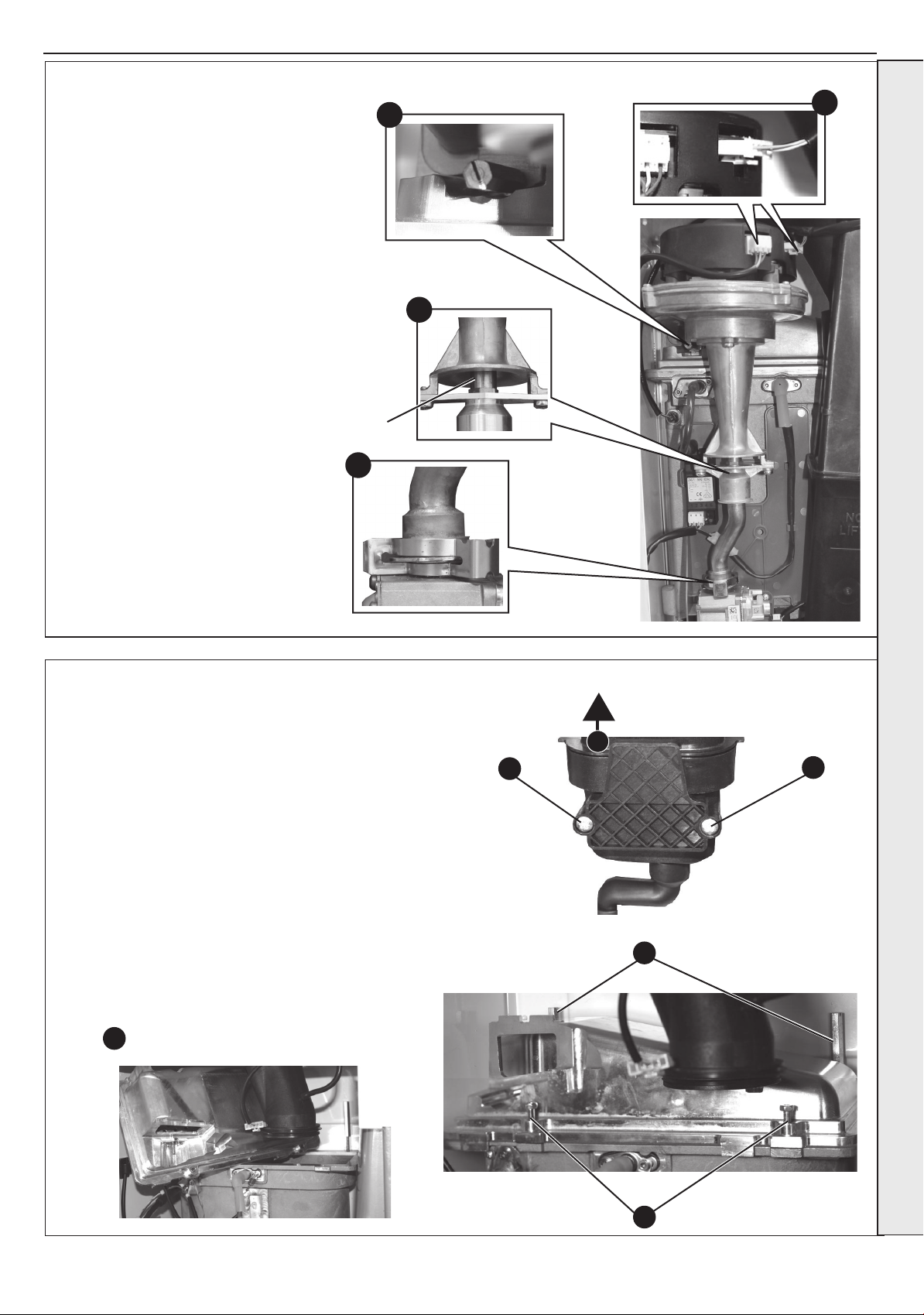
SECTION 3 - SERVICING
3.10 BURNER INJECTOR REPLACEMENT
4
1. Refer to Section 3.8.
2. Disconnect the electrical leads from the
fan.
3. Remove the clip from the gas valve to
venturi pipe and ease the pipe upwards,
rotate and ease down to remove.
4. Loosen the screw retaining the fan
mounting bracket.
5. Lift and remove the fan and venturi
assembly.
6. Remove the 2 injector housing screws.
7. Withdraw the injector housing.
8. Fit the new injector housing complete with
injector.
9. Reassemble in reverse order, ensuring
that the new gas seal supplied is located
correctly in the injector housing.
10. Check operation of the boiler. Refer to
Sections 2.22 & 2.23.
Injector
3
2
6
3.11 BURNER REPLACEMENT
1. See Section 3.4.
2. Refer to Section 3.8.
3. Undo the two screws and remove the sump cover.
4. Lift the manifold to clear the bottom sealing gasket and remove
manifold.
5. Remove the 2 front xing screws and loosen the 2 rear extended
nuts.
6. Lift off the burner from the combustion chamber. To facilitate the
removal angle the burner as shown.
7. Fit the new burner, replacing any damaged or deteriorating sealing
gasket.
8. Reassemble in reverse order. Refer to Section 3.7.
9. Check the operation of the boiler. Refer to Sections 2.22 & 2.23.
6
SERVICING
4
3
5
3
Installation and Servicing
5
43
Page 44
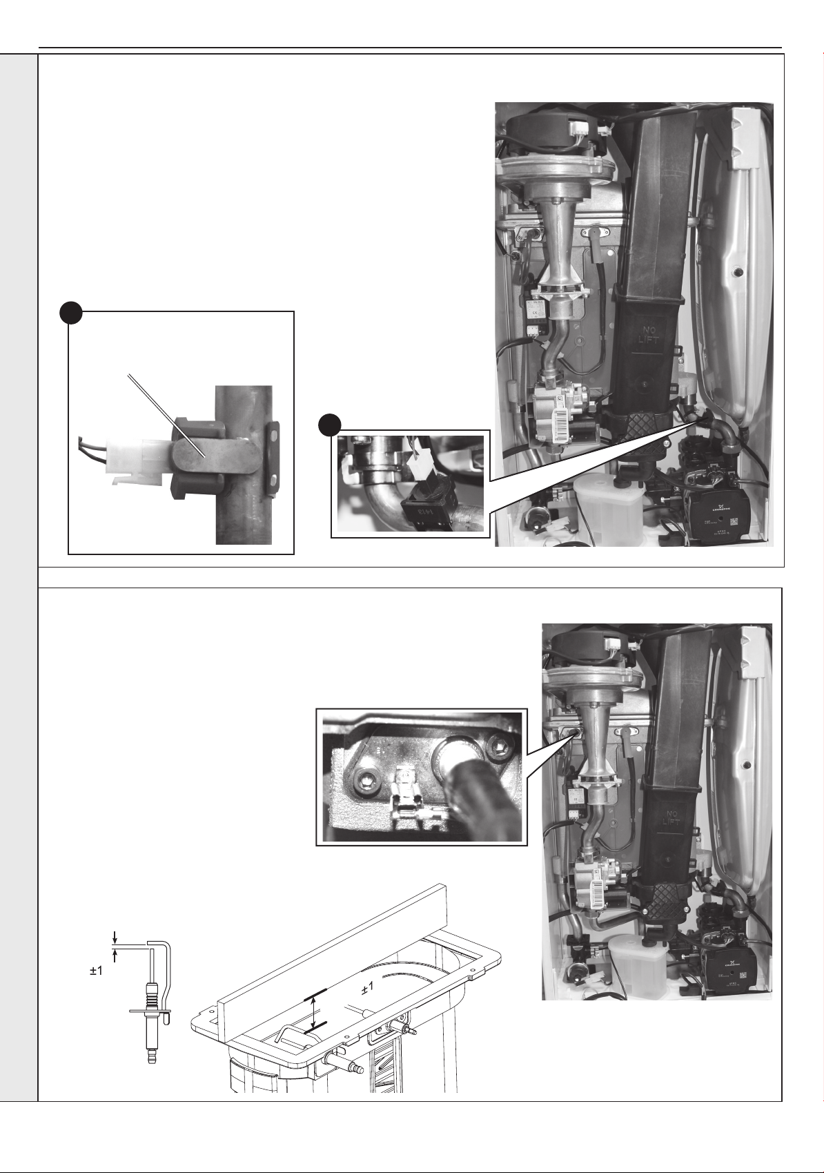
SECTION 3 - SERVICING
3mm
Straight edge
Spark Gap
3.5mm
3.12 RETURN THERMISTOR REPLACEMENT
1. Refer to Section 3.8.
2. Unclip the return thermistor from the return pipe and withdraw it from the
boiler.
3. Disconnect the electrical leads from the thermistor.
4. Reconnect the electrical lead to the new thermistor and reassemble in
reverse order, ensuring that the thermistor is securely tted to the pipe on
the thermistor locator tab as shown.
5. Check the operation of the boiler. Refer to Sections 2.22 & 2.23.
4
Thermistor Locator Tab
(with thermistor tted)
2
SERVICING
3.13 IGNITION ELECTRODE REPLACEMENT
1. Refer to Section 3.8.
2. Remove the burner. Refer to Section 3.11.
3. Unplug the ignition lead from the electrode.
4. Remove the earth lead from the ignition
electrode.
5. Remove the 2 screws holding the ignition
electrode to the combustion chamber.
6. Remove the electrode.
7. Fit the new ignition electrode, using the
new gasket supplied. Check dimensions as
shown.
8. Reassemble in reverse order.
9. Check the operation of the boiler. Refer to
Sections 2.22 & 2.23.
Ignition Electrode
44
Installation and Servicing
Page 45
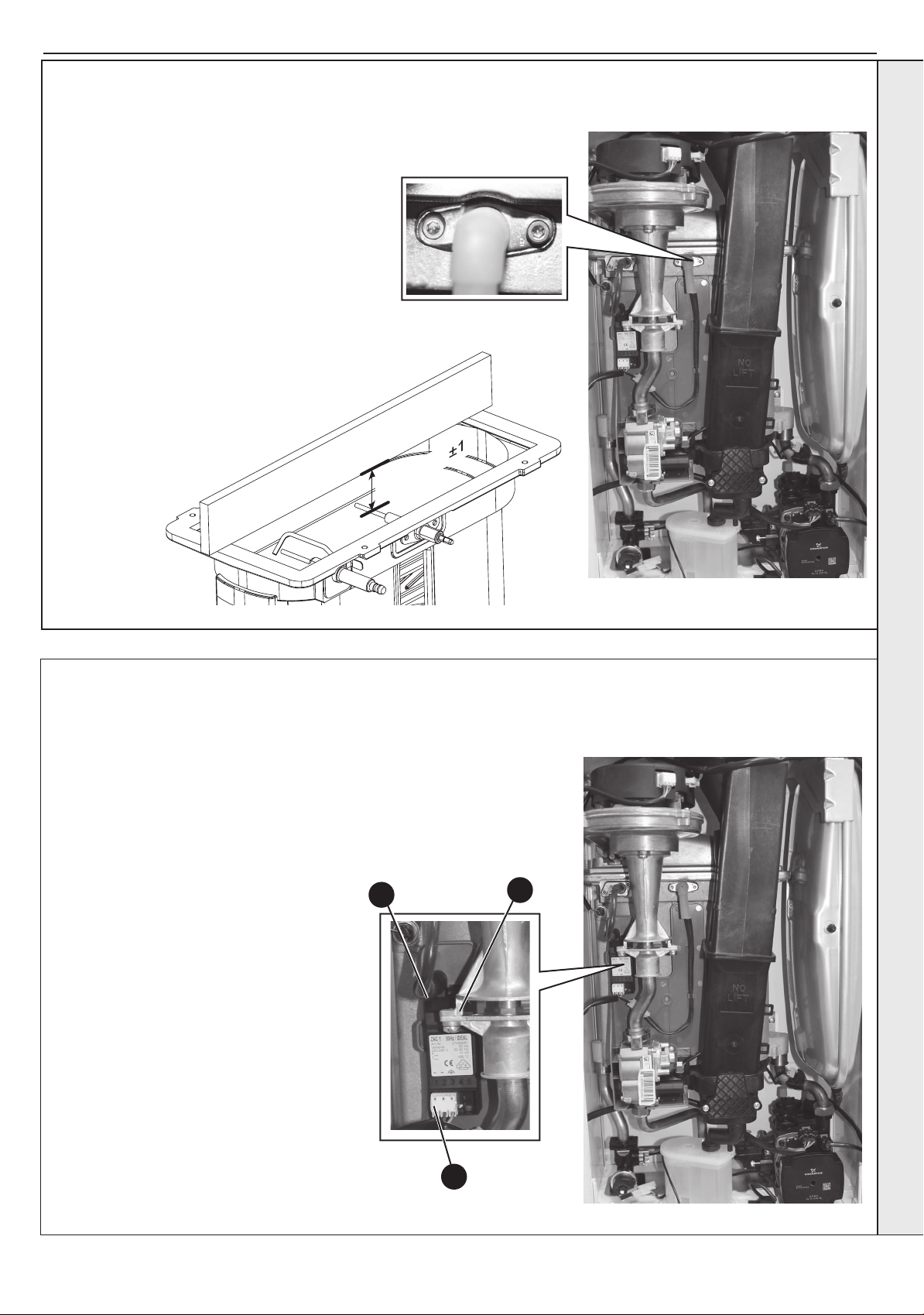
SECTION 3 - SERVICING
12.5mm
Straight edge
3.14 FLAME DETECTION ELECTRODE REPLACEMENT
1. Refer to Section 3.8.
2. Remove the burner. Refer to Section 3.11.
3. Unplug the ame detection lead from the
electrode.
4. Remove the 2 screws retaining the detection
electrode.
5. Remove the electrode.
6. Fit the new ame detection electrode, using the
new gasket supplied.
7. Reassemble in reverse order.
8. Check the operation of the boiler. Refer to
Sections 2.22 & 2.23.
Flame Detection Electrode
3.15 SPARK GENERATOR REPLACEMENT
1. Refer to Section 3.8.
2. Disconnect the leads from the spark
generator
3. Gently push down the generator
to release the top clip from the gas
valve mounting bracket.
4. Lift the spark generator up and out of
the bottom retaining moulding.
5. Fit the new spark generator and re-
assemble in reverse order ensuring
that the the earth lead is replaced
6. Check operation of the boiler .Refer
to Sections 2.22 & 2.23.
Spark Generator
2
SERVICING
3
Installation and Servicing
2
45
Page 46
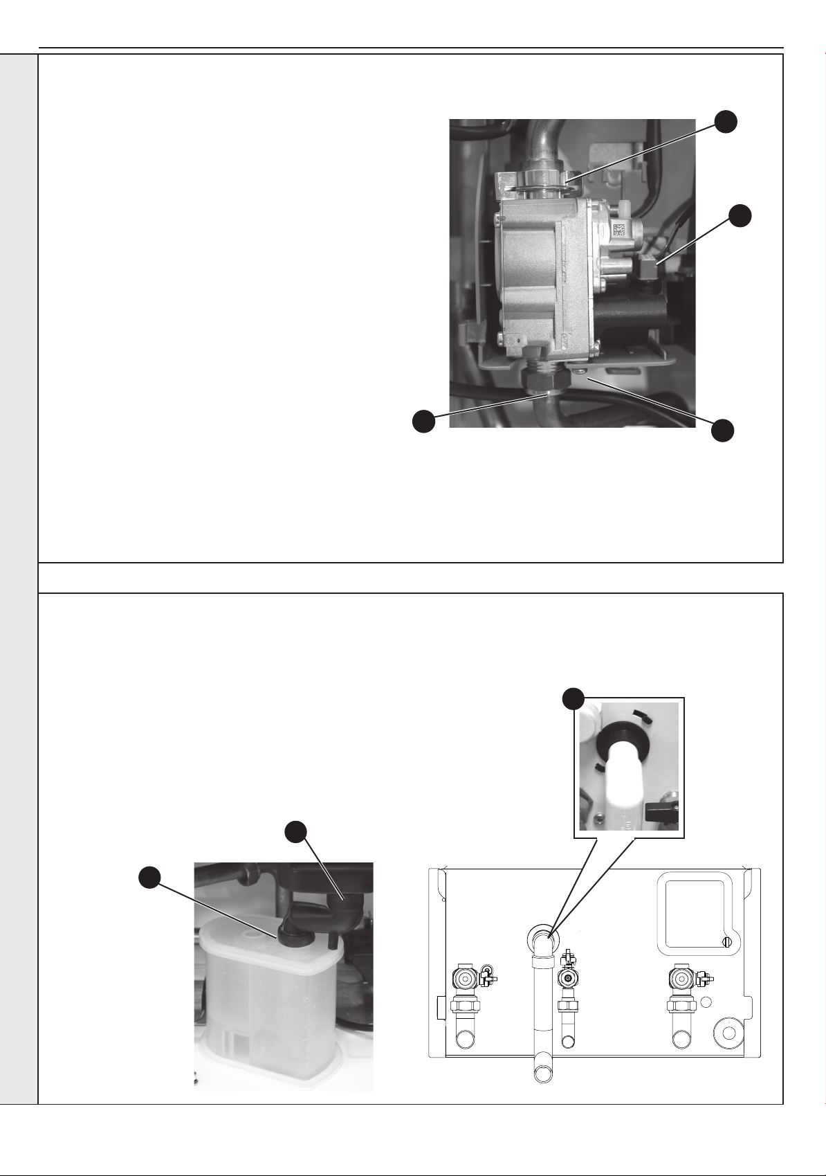
SECTION 3 - SERVICING
3.16 GAS CONTROL VALVE REPLACEMENT
1. Refer to Section 3.8.
Unplug the electrical lead connection from the gas
2.
control valve.
3. Remove the outlet gas valve clip and slide the
pipe upwards
4. Undo the gas inlet pipe union at the inlet to the
gas valve.
5. Undo the single screw xing the gas valve to
the mounting bracket and withdraw the valve
forwards.
6. Fit the new gas control valve ensuring that the
O ring and sealing washer are in place and
reconnect gas and electrical connections.
7. Check operation of the boiler. Refer to Sections
2.22 & 2.23.
3
2
4
5
SERVICING
3.17 CONDENSATE TRAP/SIPHON REPLACEMENT
1. Refer to Section 3.8.
Note: Ensure condensate trap is fully drained before removal.
2. Pull off the rubber pipe at the sump drain.
3. Disconnect the condensate drain pipe.
4. Turn the siphon clockwise to disengage and lift to remove.
5. Reassemble in reverse order.
6. When reassembling ensure the trap is full of water.
7. Check operation of the boiler. Refer to Sections 2.22 & 2.23.
2
3
4
46
Installation and Servicing
Page 47
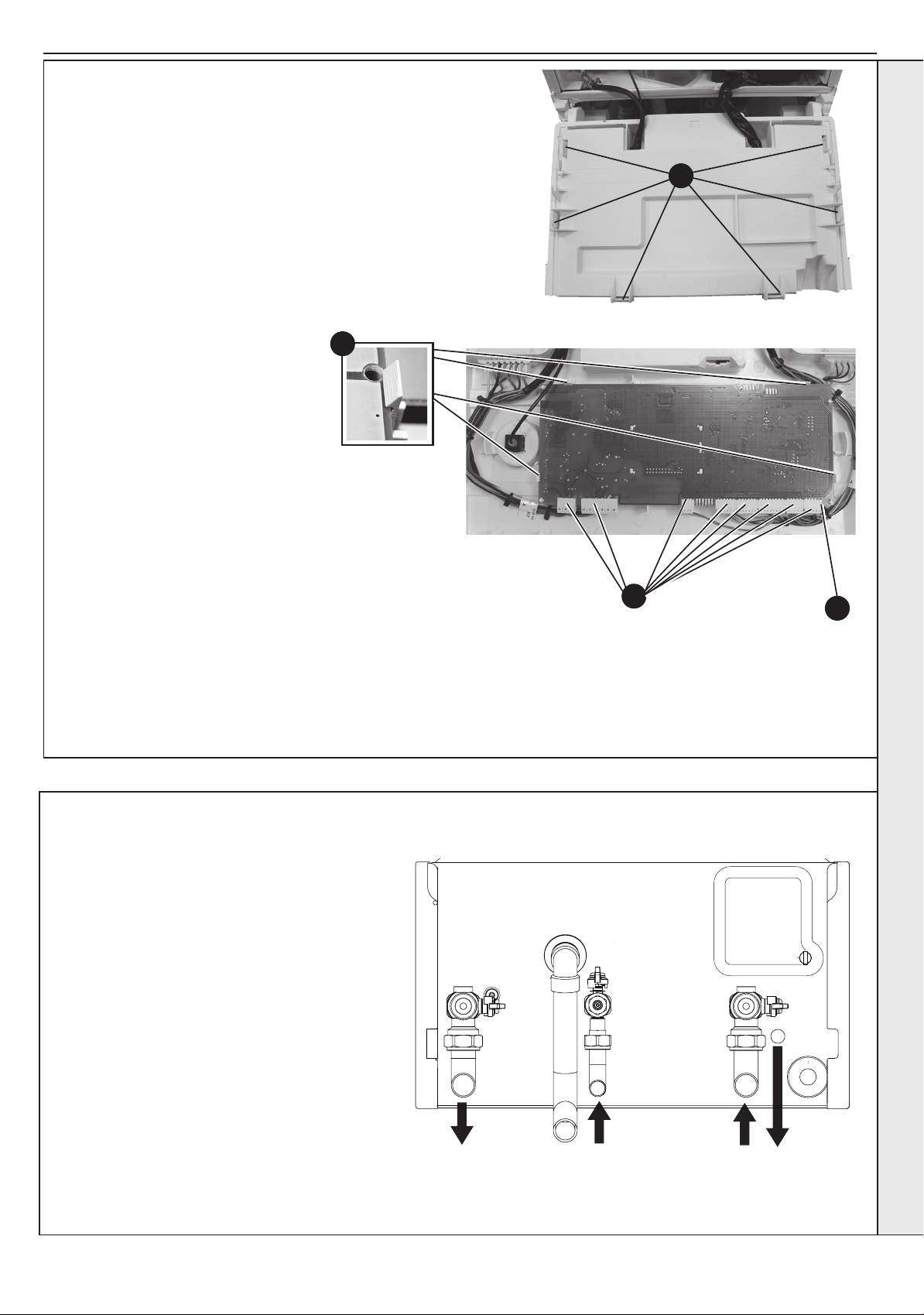
SECTION 3 - SERVICING
CH
Flow
Gas
CH
Return
CH
Circuit
Drain
3.18 PCB REPLACEMENT
Note. Fit the earth strap provided with the PCB to your wrist and
secure to a suitable earth on the boiler chassis.
1. Refer to Section 3.8.
2. Ensure the control knobs are in the 12 o clock position.
3. Carefully release the six retaining clips and remove control
box cover.
4. Unplug all lead connections to the PCB, also where
applicable, push the small plastic clip with an electrical
screwdriver to facilitate plug removal.
5. Spring out the four side retaining clips and pull the PCB
upwards to clear the 4 corner retaining posts.
6.
Take the new PCB.
7. Re-connect all plug connections.
8. Reassemble in reverse order.
9. a. Turn power on, display shows uP.
Rotate both dials fully
anti-clockwise.
b. Press RESTART, display shows oF
c. Turn power off
d. Turn power on, display shows F9
e. Using central heating knob, rotate clockwise or
anticlockwise to show “Su” for System, then press
RESTART button.
f. Using central heating knob, rotate clockwise or
anticlockwise to show “n” for Natural Gas, then press
restart button.
g. Using central heating knob rotate clockwise or
anticlockwise to show boiler size, select 30, then press
RESTART button.
h. Display shows “Su”, “n”, “30”, internal number.
j. Press restart. New PCB is now programmed.
10.
Check that the boiler operates in both DHW and CH modes.
5
3
4
Plastic clip
IMPORTANT.IT IS CRITICAL FOR SAFE
OPERATION THAT THE CORRECT BOILER SIZE
AND FUEL TYPE IS ENTERED INTO THE BOILER.
4
SERVICING
3.19 DRAINING THE BOILER
CENTRAL HEATING CIRCUIT
1. Refer to Section 3.8.
2. Close all the CH water isolating valves on the
boiler inlet.
3. To drain the primary heat exchanger circuit:
Open the drain valve and attach a length of hose
to the CH drain point.
4. After replacing any component on the boiler,
remove the hose, close the drain valve and
open all system isolating valves (re-pressurise
as appropriate) before proceeding to check
operation of the boiler.
5. Check operation of the boiler. Refer to Sections
2.22 & 2.23.
Installation and Servicing
47
Page 48
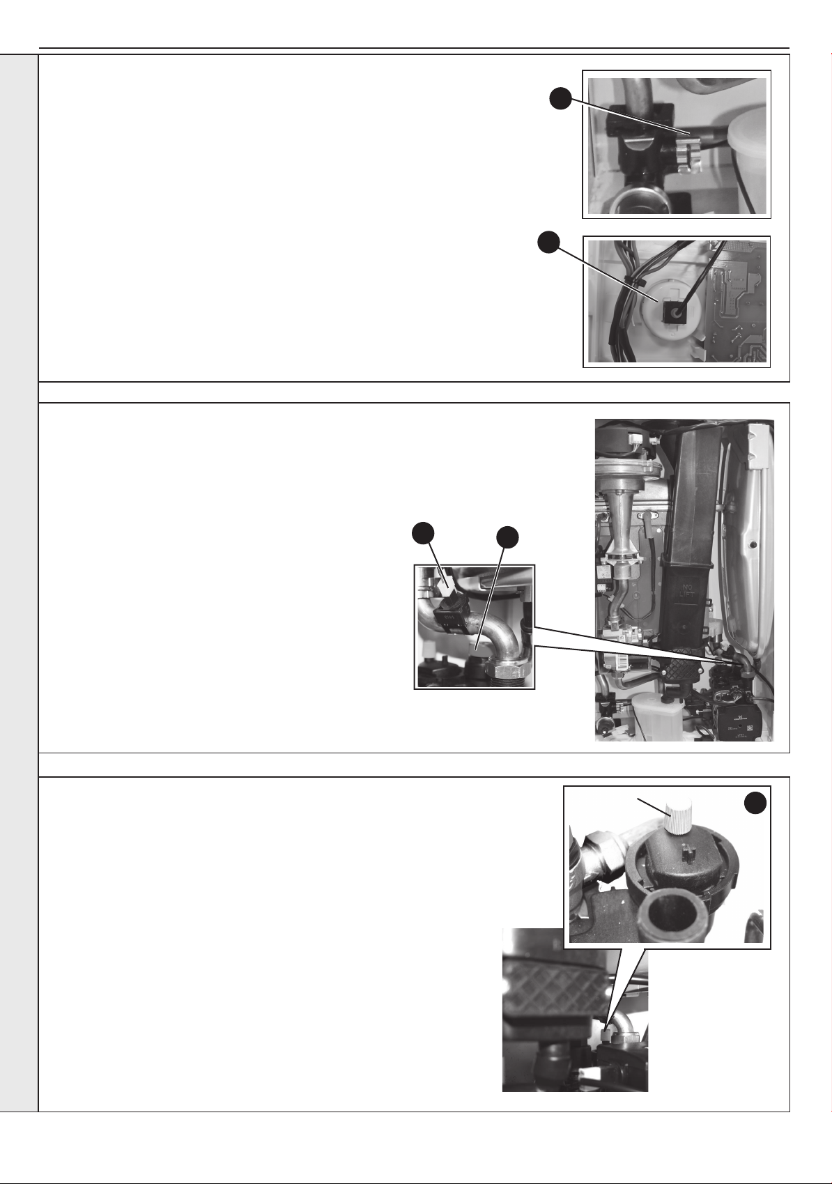
SECTION 3 - SERVICING
3.20 PRESSURE GAUGE REPLACEMENT
1. Refer to Section 3.8.
2. Drain the heating system. Refer to Section 3.19.
3. Remove the boiler front (See Section 3.2), lower the control panel and remove
the control box cover.
4. Ensuring there is no pressure in the system unclip the C clip from the ow
manifold port and remove the capillary connection together with ‘o’ ring.
5. Releasing the two retaining clips on the pressure gauge ease the pressure
gauge through the front of the control panel.
6. Fit the new pressure gauge from the front of the control panel ensuring correct
orientation. Locate push t connection into port ensuring ‘o’ ring in place and
secure with the C clip.
7. Rell the boiler. Refer to Section 2.13.
8. Check the operation of the boiler. Refer to Sections 2.22 & 2.23.
3.21 SAFETY RELIEF VALVE REPLACEMENT
4
5
1. Refer to Section 3.8.
2. Drain the boiler. Refer to Section 3.19.
Remove the clip on return thermistor. Refer to Section 3.12.
3.
4. Pull out and remove the clip (positioned behind the safety
valve) retaining the safety valve.
5. Undo the safety valve pipe compression tting positioned
outside the boiler casing.
SERVICING
6. Lift out the safety valve/pipe assembly.
7. Remove the safety valve pipe and transfer to the new
safety valve.
8. Reassemble in reverse order ensuring the retaining clip is
correctly tted, the pipe compression tting retightened and
return thermistor is re-clipped.
9. Rell the boiler. Check operation of the boiler. Refer to
Sections 2.22 & 2.23.
3
3.22 PUMP AUTOMATIC AIR VENT REPLACEMENT
1. Refer to Section 3.8.
2. Drain the boiler. Refer to Section 3.19.
3. Remove the expansion vessel. Refer to Section 3.27.
4. Firstly, increase access area by disconnecting the 22mm pipe connection
at top of pump chamber and bottom of heat exchanger and remove pipe.
5. The automatic air vent head is retained in the pump body with a bayonet
connection. The air vent head and oat assembly is removed by turning
the head anti-clockwise (viewed from above) and pulling upwards.
6. Reassembly is the reverse of the above. Ensure the air vent head ‘o’ ring
seal is in place when retting and the new ‘o’ ring is tted to the return pipe
top connection.
7. Ensure the air vent cap is loose.
8. Rell the boiler. Refer to Section 2.13. Check for leaks around the new air
vent joint.
9. Check the operation of the boiler. Refer to Sections 2.22 & 2.23.
4
Dust Cap
5
48
Installation and Servicing
Page 49
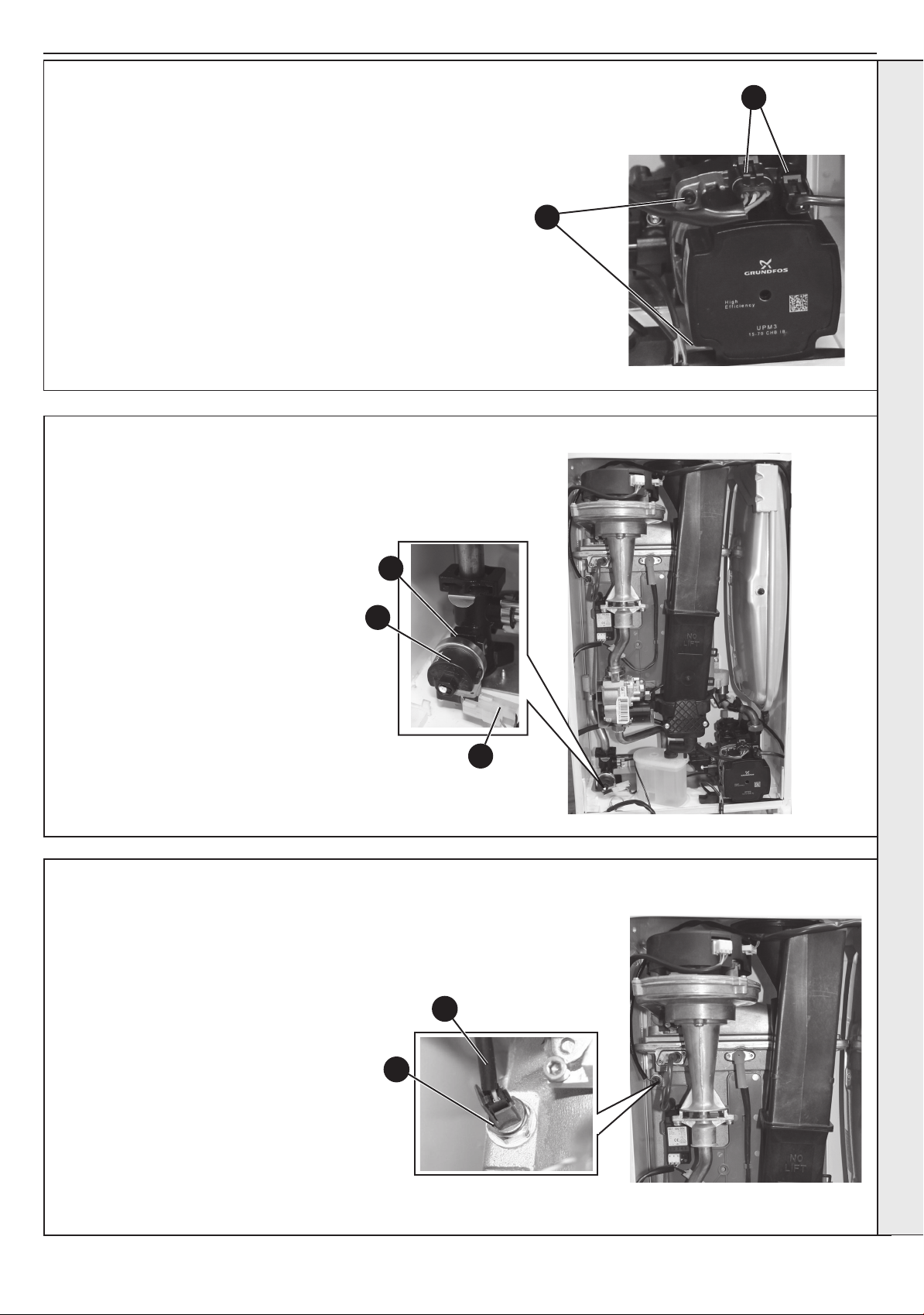
SECTION 3 - SERVICING
3.23 PUMP HEAD REPLACEMENT
1. Refer to Section 3.8.
2. Drain the boiler. Refer to Section 3.19.
3. Disconnect the two electrical leads from the pump.
4. Remove the 4 Allen screws retaining the pump head.
5. Remove the pump head.
6. Fit the new pump head.
7. Reassemble in reverse order.
8. Rell the boiler. Refer to Section 2.13.
9. Check operation of the boiler. Refer to Sections 2.22 & 2.23.
3.24 CH WATER PRESSURE SWITCH REPLACEMENT
1. Refer to Section 3.8.
2. Drain the boiler. Refer to Section 3.19.
3. Pull off the two electrical connections.
4. Using a suitable tool, pull out the metal
retaining clip.
5. Carefully withdraw the pressure switch.
6. Fit the new pressure switch and reassemble in reverse order.
7. Rell the boiler.
8. Check operation of the boiler. Refer to
Sections 2.22 & 2.23.
4
5
3
4
3
3.25 CONTROL / NO FLOW THERMISTOR REPLACEMENT
1. Refer to Section 3.8.
2. Drain down the boiler. Refer to Section 3.19.
3. Unplug the electrical lead.
4. Unscrew the thermistor (to facilitate removal
a 13mm socket spanner should be used).
5. Fit the new thermistor using the sealing
washer provided.
6. Reassemble in the reverse order.
7. Rell the boiler. Refer to Section 2.13.
8. Check the operation of the boiler. Refer to
Sections 2.22 & 2.23.
4
3
SERVICING
Installation and Servicing
49
Page 50
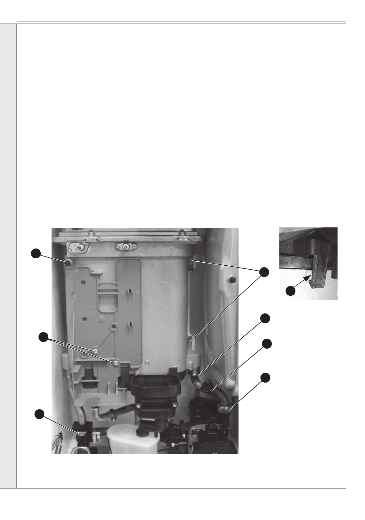
SECTION 3 - SERVICING
3.26 HEAT ENGINE REPLACEMENT
Refer also to Section 2.1 - ‘Boiler Exploded View’
IMPORTANT
Before starting the removal procedure, protect the gas and electrical controls with a waterproof sheet or plastic bag.
1. Refer to Section 3.8.
2. Drain the boiler. Refer to Section 3.19.
3. Remove the fan / venturi assembly and place on one side.
Refer to Section 3.3
Remove the burner and place on one side. Refer to Section
4.
3.4.
5. Remove the ignition and detection electrodes. Refer to
Sections 3.13 & 3.14.
6. Remove the spark generator. Refer to Section 3.15.
7. Remove the gas valve. Refer to Section 3.16.
8. Remove the expansion vessel. Refer to Section 3.27.
9. Remove the ow and return thermistor. Refer to Sections
3.12 & 3.25.
10. Remove the 2 M5 screws retaining the gas valve mounting
bracket and transfer bracket to the new heat exchanger.
11. Undo the pump union nut and remove pipe.
12. Remove the two retaining spring clips and remove pipes.
13. Remove the condensate rubber pipe. Refer to Section 3.17, no. 2.
14. Remove the two heat exchanger xing screws.
15. Remove the Heat exchanger, slide out of location bracket.
16. If replacement sump required: Rotate heat exchanger assembly
180º. Place new sump onto heat exchanger, ensuring correct
orientation and seal is in place. Then gently apply pressure to
the base of the sump at each tab xing point and engage tabs
onto the heat exchanger.
17. Reassemble in reverse order, ensuring the heat exchanger LH
retaining bracket is correctly positioned. Replace any new ‘o’
rings supplied with new heat exchanger and replacing gaskets
or seals if any sign of damage is evident. When replacing the
spring clips located on the return pipe connection, ensure clip is
oriented to correctly match connecting pipe diameters.
18. Ensure the trap/siphon is lled with water. Refer to Secion 3.17.
19. Rell the boiler. Refer to Section 2.13.
20. Check operation of the boiler. Refer to Section 2.22 & 2.23.
Shown as 180º position
9
SERVICING
14
16
12
10
9
11
12
50
Installation and Servicing
Page 51

SECTION 3 - SERVICING
3.27 EXPANSION VESSEL RECHARGING & REPLACEMENT
RECHARGING
1. Remove the charge point cover.
2. Recharge the tank pressure to 0.75 bar.
3. Re-assemble in reverse order
4. Check operation of the boiler. Refer to
Sections 2.22 & 2.23.
REPLACEMENT
5. Refer to Section 3.8.
Drain the boiler CH circuit. Refer to Section
6.
3.19.
7. Remove the retaining clip on the vessel
water connection pipe.
8. Support the expansion vessel and unscrew
the 2 screws from the securing clamp,
located on the top of the boiler, and remove.
(Note the position of the bracket on the
vessel)
9. Remove the expansion vessel.
10. Fit the new expansion vessel.
11. Reassemble in reverse order ensuring the
“o” ring is in place.
12. Rell the boiler. Refer to Section 2.13.
13. Check operation of the boiler. Refer to
Sections 2.22 & 2.23.
7
Recharge
Point
8
SERVICING
Installation and Servicing
51
Page 52
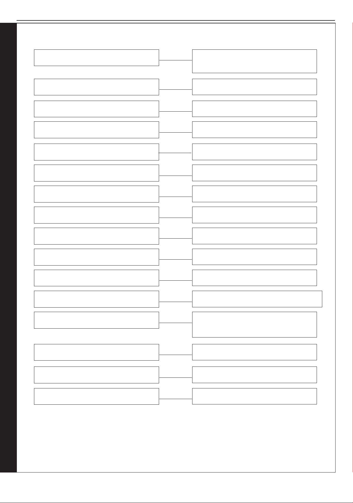
SECTION 4 - FAULT FINDING
4.1 FAULT FINDING CHART MAIN MENU
In order to assist fault nding the boiler has a 7 segment display. The key to the display codes is as follows:
‘L1’
‘L2’
‘LC’
‘L6’
‘F1’
‘F2’ or ‘Fn’ or ‘Ln’
‘F3’
‘L4’ or ‘F4’
GO TO SECTION 4.2 -
FLOW TEMPERATURE OVERHEAT LOCKOUT
or NO WATER FLOW LOCKOUT
GO TO SECTION 4.3 -
IGNITION LOCKOUT
5 RESTARTS WITHIN 15 MINS -
TURN POWER OFF AND ON
GO TO SECTION 4.4 -
FALSE FLAME LOCKOUT
GO TO SECTION 4.5 -
LOW WATER PRESSURE
GO TO SECTION 4.6 -
FLAME LOSS
GO TO SECTION 4.7 -
FAN FAULT
GO TO SECTION 4.8 -
CONTROL / NO FLOW THERMISTOR FAULT
‘L5’ or ‘F5’
‘F6’
‘F7’
‘F9’ or ‘L9’ or ‘F8’ or ‘L8’
‘FU’
NO CH
NO HW
NO DISPLAY
GO TO SECTION 4.9 -
RETURN THERMISTOR FAULT
GO TO SECTION 4.10 -
OUTSIDE SENSOR FAULT
LOW MAINS VOLTAGE -
CONTACT ELECTRICITY PROVIDER
PCB UNCONFIGURED OR FAULT. SEE SECTION
3.18. IF FAUL PERSISTS REPLACE PCB
DIFF GREATER THAN 50ºC. CHECK ISOLATION
VALVES ARE OPEN, CHECK PUMP, CHECK RAD
VALVES OPEN, CHECK SYSTEM BLOCKAGES.
GO TO SECTION 4.11
GO TO SECTION 4.13
GO TO SECTION 4.12
FAULT FINDING FAULT FINDING FAULT FINDING FAULT FINDING FAULT FINDING
RESTART PROCEDURE - To restart boiler, press the “RESTART” button.
52
Installation and Servicing
Page 53
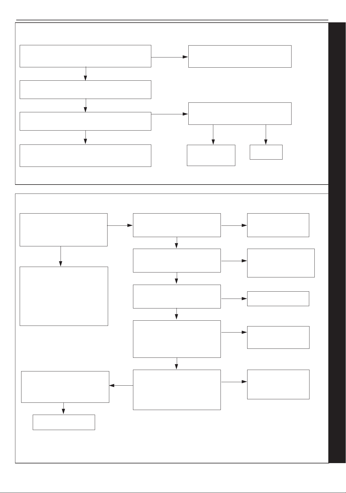
SECTION 4 - FAULT FINDING
4.2 ‘L1’ - FLOW TEMPERATURE OVERHEAT LOCKOUT OR NO WATER FLOW LOCKOUT
Is the Boiler and CH System lled with water and all
isolation and radiator valves open?
YES
If the PCB has been replaced check a BCC has been
tted then restart the boiler.
Is the Flow/Return Differential across the Boiler in
excess of 30°C?
NO
Check the Control/No Water Flow and Return
Thermistors (Refer to Sections 3.12 & 3.25)
RESTART PROCEDURE - To restart boiler, press the “RESTART” button.
NO
YES
4.3 ‘L2’ - IGNITION LOCKOUT
Fill and vent the system and open all
isolation valves, then restart boiler
Check that the Pump is rotating freely. Is
the Differential now below 20°C?
NO
Replace the Pump,
then restart boiler
YES
OK, now
restart boiler
If the boiler is restarted does the
boiler ignite for a short time and
then extinguish?
YES
Check the detection electrode
and associated harness for:
continuity, visual condition and
position (Refer to Section 3.14).
Check if the condensate pipe is
blocked.
Check ue is installed correctly.
Replace as necessary
Check siphon and condensate
drain pipe work for blockage and
rectify if necessary. Boiler now
working OK?
NO
NO
YES
Is the Gas Pressure available at
the Boiler Inlet (>18 mbar)?
YES
Is 24Vdc supply available at the
Gas Valve?
YES
Unplug gas valve. Is resistance
between outside pins 4KΩ (±2)?
YES
Check spark generator and
associated harness for: continuity
and visual condition. (Refer
to Section 3.15) Are these
functioning correctly?
YES
Check ignition electrode and
associated harness for: continuity,
visual condition and position.
(Refer to Section 3.13) Are these
functioning correctly?
NO
NO
NO
NO
NO
Check gas supply and
rectify fault
Check wiring connection
from gas valve to PCB for
continuity. If the wiring is
OK then replace the PCB
Replace Gas Valve
Replace Spark
Generator and harness
as necessary
Replace Ignition
Electrode and
associated harness as
necessary
Replace Gas Valve
RESTART PROCEDURE - To restart boiler, press the RESTART button.
Installation and Servicing
FAULT FINDING FAULT FINDING FAULT FINDING FAULT FINDING FAULT FINDING
53
Page 54
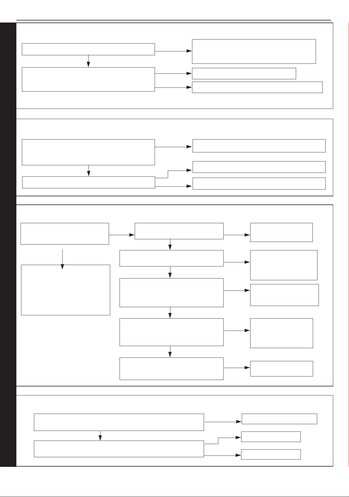
SECTION 4 - FAULT FINDING
4.4 ‘L6’ - FALSE FLAME LOCKOUT
Restart the boiler, does Boiler Work OK?
NO
Separate the ame detection electrode in-line
connector. Is there continuity between the terminals
pins connected to the electrode?
RESTART PROCEDURE - To restart boiler, press the “RESTART” button.
YES
YES
NO
4.5 ‘F1’ - LOW WATER PRESSURE
Is the Boiler and CH System lled with water and all
isolation and radiator valves open (check pressure
gauge is between 1 to 1.5 bar)?
YES
Are connections on water pressure sensor secure?
NO
NO
YES
4.6 ‘F2’ OR ‘Fn’ OR ‘Ln’ - FLAME LOSS
Check routing and integrity of internal boiler
wiring is OK. Check condition of Flame Sense
Electrode and replace if deteriorated.
Replace Flame Detection Electrode
Check routing and integrity of internal boiler wiring.
Fill and vent the system and open all isolation valves
Re-t connections
Replace water pressure sensor
Does the boiler ignite for a short
time and then extinguish?
YES
Check the detection electrode and
associated harness for: continuity,
visual condition and position
(Refer to Section 3.14). Check if
condensate pipe is blocked. Check
if ue is blocked.
Replace as necessary
NO
Is the Gas Pressure available at
the Boiler Inlet (18 mbar)?
YES
Is 24Vdc supply available at the Gas
Valve while the ame is on?
YES
Check spark generator and associated
harness for: continuity and visual
condition. (Refer to Section 3.15) Are
these functioning correctly?
YES
Check ignition electrode and associated
harness for: continuity, visual condition
and position. (Refer to Section 3.13) Are
these functioning correctly?
YES
Check siphon and condensate drain pipe
work for blockage and rectify if necessary.
Boiler now working OK?
NO
NO
NO
NO
NO
Check gas supply and
rectify fault
Check wiring from gas
valve to PCB for continuity.
If the wiring is OK then
replace the PCB
Replace Spark Generator
and Harness as necessary.
Replace Ignition
Electrode and
associated harness as
necessary
Replace Gas Valve
4.7 ‘F3’ - FAN FAULT
Does the wiring from the Fan to the PCB have secure connections at
both ends and has not deteriorated? Does the wiring have continuity?
FAULT FINDING FAULT FINDING FAULT FINDING FAULT FINDING FAULT FINDING
Is there 230Vac at the Blue and Brown connections
to the 3 way connection on the Fan?
54
YES
NO
NO
YES
Rectify Wiring & connections
Replace PCB
Replace Fan
Installation and Servicing
Page 55
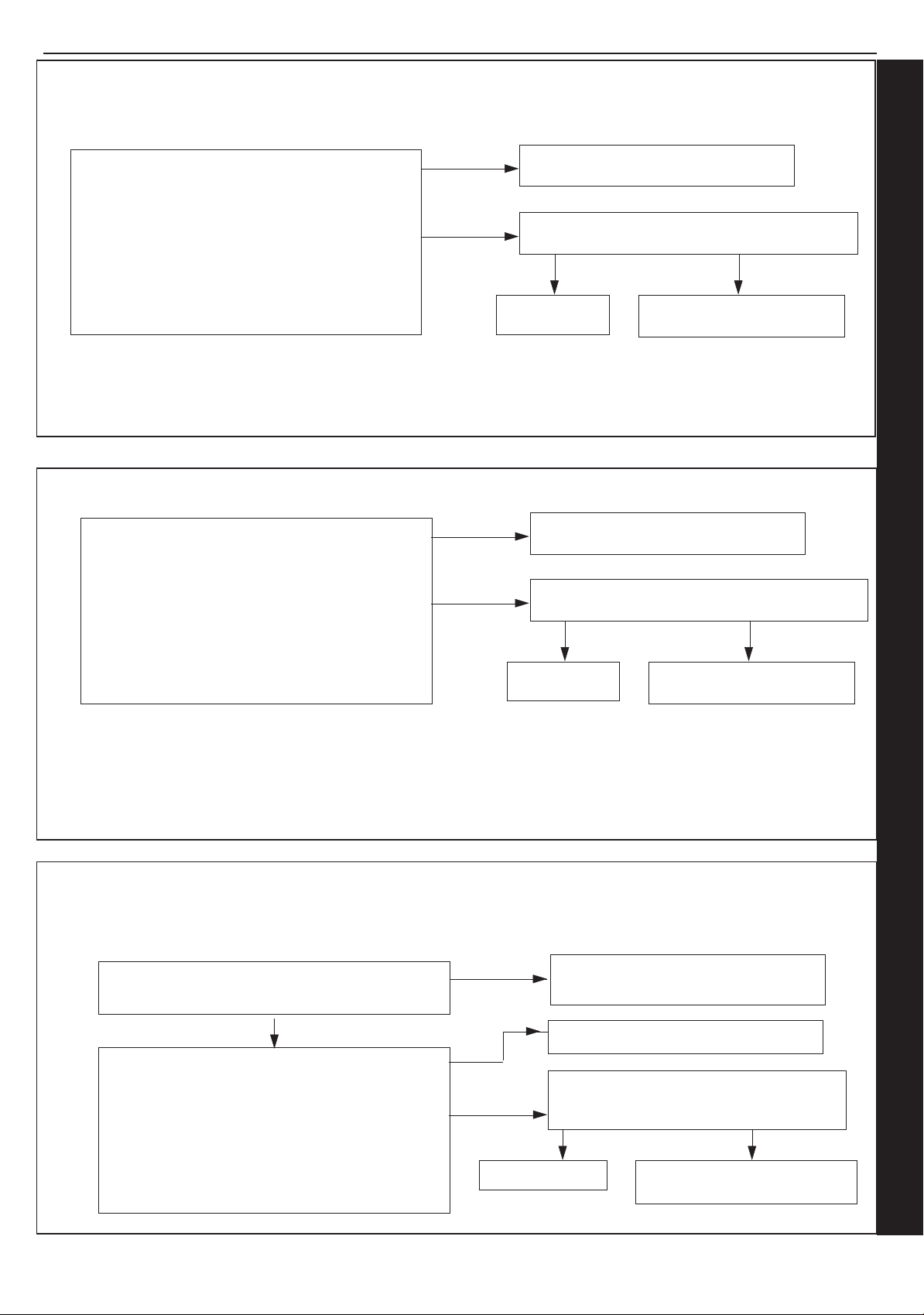
SECTION 4 - FAULT FINDING
4.8 ‘L4’ OR ‘F4’ - CONTROL / NO FLOW THERMISTOR FAULT
Remove the Control/No Flow Thermistor from the
NO
Heat Exchanger and disconnect the wires.
Check the resistance using a suitable multimeter
connected across the thermistors terminal pins.
o
At 25
At 60
At 85
C expect 9,700 - 10,300 Ohms
o
C expect 2,400 - 2,600 Ohms
o
C expect 1,000 - 1,100 Ohms
YES
Is the Thermistor value correct?
4.9 ‘F5 OR L5’ - RETURN THERMISTOR FAULT
Remove the Return Thermistor from the CH Return
Pipe and disconnect the wires.
Check the resistance using a suitable multimeter
connected across the thermistors terminal pins.
o
At 25
At 60
At 85
C expect 9,700 - 10,300 Ohms
o
C expect 2,400 - 2,600 Ohms
o
C expect 1,000 - 1,100 Ohms
Is the Thermistor value correct?
NO
YES
Fit a new Thermistor
Is there continuity between the PCB and Thermistor?
YES
Replace PCB
Check and replace wiring as
NO
necessary
Fit a new Thermistor
Is there continuity between the PCB and Thermistor?
YES
Replace PCB
Check and replace wiring as
NO
necessary
4.10 ‘F6’ - OUTSIDE SENSOR FAULT
Is the wiring securely connected at both the boiler and
Outside Sensor?
Disconnect the wires to the outside sensor.
Check the resistance using a suitable multimeter
connected across the Outside Sensors terminal pins.
o
C expect 31,000 - 35,000 Ohms
At 0
o
At 15
At 30
Installation and Servicing
C expect 15,000 - 16,500 Ohms
o
C expect 7,700 - 8,500 Ohms
Is the Outside Sensor value correct?
YES
NO
NO
YES
Replace PCB
Securely connect the wiring at both the
boiler and Outside Sensor
Fit a new Outside Sensor
Is the wiring securely connected between the
incoming terminal block boiler connection of
the Outside Sensor and the PCB?
YES NO
Securely connect the wiring at
the Terminal Block and the PCB
FAULT FINDING FAULT FINDING FAULT FINDING FAULT FINDING FAULT FINDING
55
Page 56
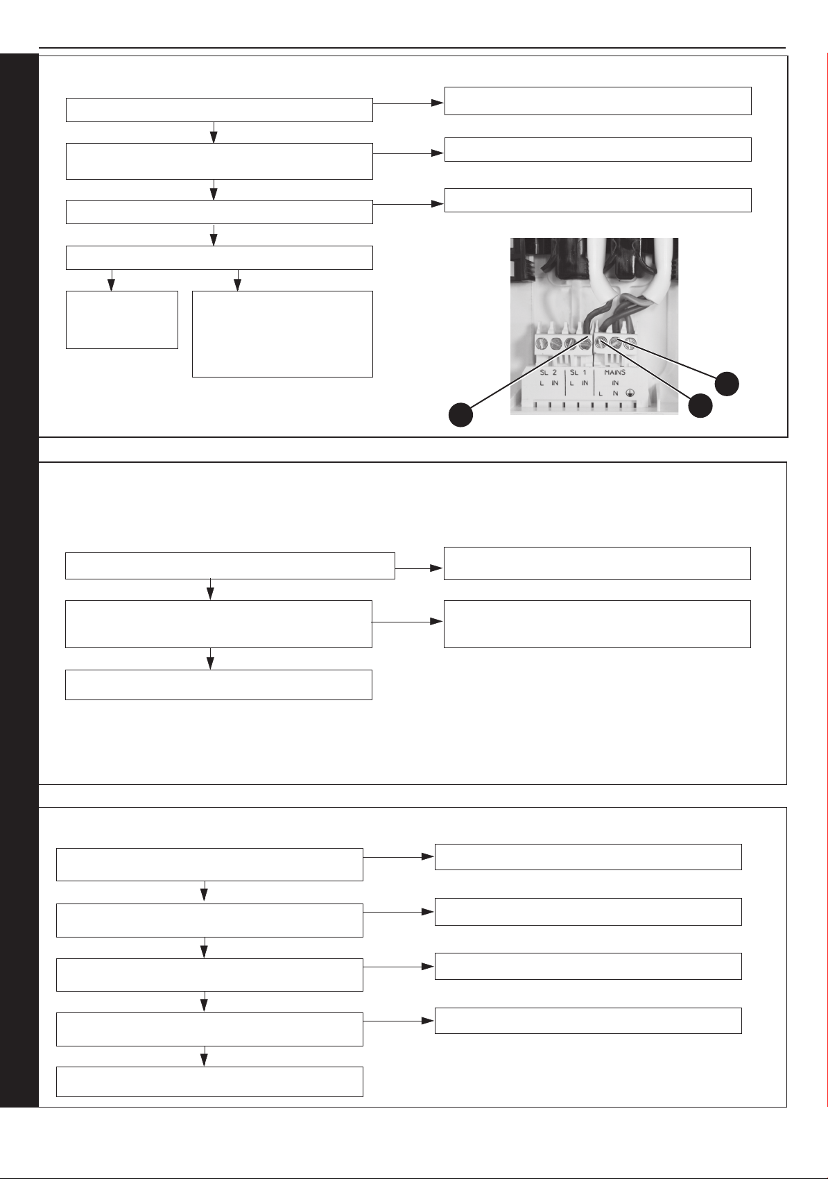
SECTION 4 - FAULT FINDING
4.11 NO CH OPERATION
Is the mode knob in the ON position?
YES
Are the Timer and the Room Thermostat or cylinder
thermostat switched on?
YES
Are the Radiator Valves Open?
YES
Is there 230Vac at (A)?
YES NO
Check wiring from
terminal strip to
PCB.
There is no Voltage from the
Timer/Room Stat. This is not
boiler fault. Ensure Voltage is
supplied to boiler by rectifying
external wiring.
NO
NO
NO
Move the mode knob to the ON position
Switch the Timer, Room Stat and Cylinder Stat On
Open the Radiator Valves
A
L
N
4.12 NO DISPLAY
Is there 230Vac to the boiler at L and N (see Section 4.11)?
YES
Is the wiring from the terminal block to the Main PCB
connected securely?
YES
Replace the PCB
4.13 NO HW
Is the cylinder stat calling for heat?
NO
NO
NO
Supply power to the boiler
Connect the wiring from the terminal block to the
Main PCB securely.
Adjust cylinder stat
YES
Is DHW timer on?
YES
Is boiler mode knob in the ON position?
YES
Is there 230V at (A)? Refer to Section 4.11
FAULT FINDING FAULT FINDING FAULT FINDING FAULT FINDING FAULT FINDING
Check wiring from terminal strip to PCB.
YES
56
NO
NO
NO
Switch timer on
Move the mode knob to the ON position
Check system controls and wiring
Installation and Servicing
Page 57

SHORT LIST OF PARTS
When replacing any part on this appliance use only spare parts that you can be assured conform to the safety and performance
specication that we require. Do not use reconditioned or copy parts that have not been clearly authorised by Keston. Failure to do so
could affect safety or performance of this appliance.
Our Parts team are also available to help with your Keston Spare Parts enquiries on 01482 498665.
When calling, and to ensure we can provide you with the most accurate parts information, please ensure you have the following to
hand;
- Boiler Model
- Appliance GC Number
- Boiler Serial Number
IMPORTANT NOTE.
Propane Boilers - After installation of a conversion kit, and when ordering future spares be sure to quote the serial letter code AAV which indicates a Propane boiler - and the boilers original serial letter code from the original data plate.
Installation and Servicing
57
Page 58
Page 59

Benchmark Commissioning and
Servicing Section
It is a requirement that the boiler is installed and commissioned to the
manufacturers instructions and the data fields on the commissioning checklist
completed in full.
To instigate the boiler guarantee the boiler needs to be registered with the
manufacturer within one month of the installation.
To maintain the boiler guarantee it is essential that the boiler is serviced annually
by a Gas Safe registered engineer who has been trained on the boiler installed.
The service details should be recorded on the Benchmark Service Interval
Record and left with the householder.
www.centralheating.co.uk
© Heating and Hotwater Industry Council (HHIC)
Page 60
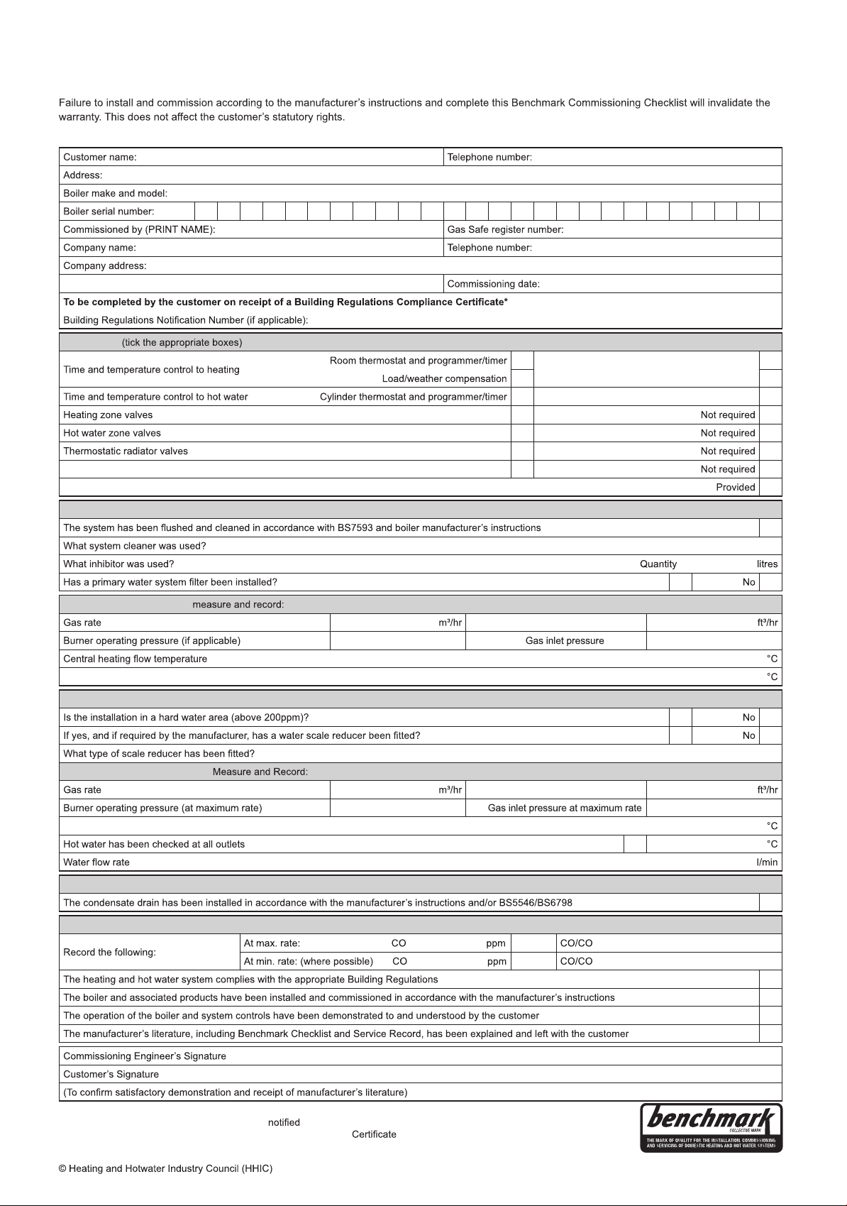
GAS BOILER SYSTEM COMMISSIONING CHECKLIST
This Commissioning Checklist is to be completed in full by the competent person who commissioned the boiler as a means of demonstrating
compliance with the appropriate Building Regulations and then handed to the customer to keep for future reference.
CONTROLS
Programmable room thermostat
Optimum start control
Combination Boiler
Fitted
Fitted
Fitted
Automatic bypass to system Fitted
Boiler interlock
ALL SYSTEMS
Yes
CENTRAL HEATING MODE
Central heating return temperature
COMBINATION BOILERS ONLY
DOMESTIC HOT WATER MODE
Cold water inlet temperature
CONDENSING BOILERS ONLY
ALL INSTALLATIONS
Yes
OR
mbar OR mbar
Yes
Yes
OR
mbar OR mbar
Yes Temperature
Yes
AND
AND
²
²
Ratio
Ratio
Yes
Yes
Yes
Yes
* All installations in England and Wales must be to Local Authority Building Control (LABC) either directly or through a
Competent Persons Scheme. A Building Regulations Compliance
will then be issued to the customer.
www.centralheating.co.uk
www.centralheating.co.uk
Page 61
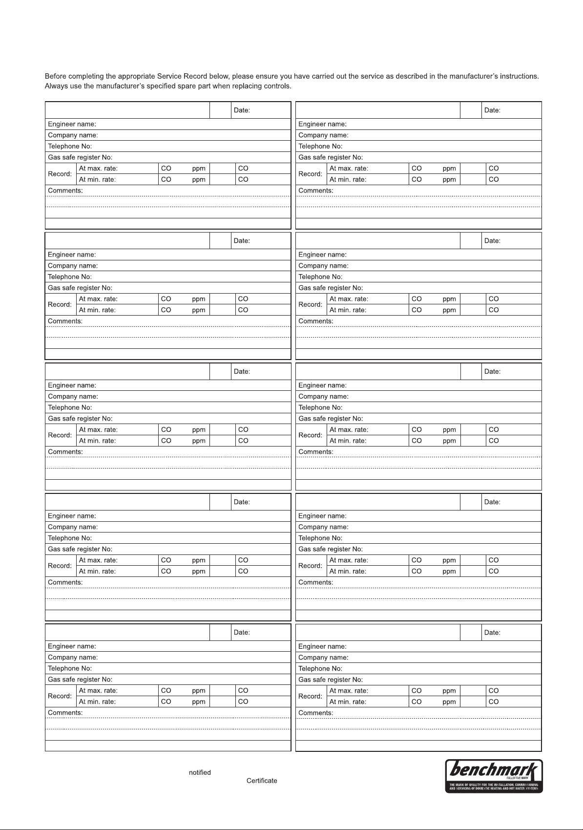
SERVICE RECORD
It is recommended that your heating system is serviced regularly and that the appropriate Service Interval Record is completed.
Service Provider
SERVICE 01
(Where Possible) AND
Signature
SERVICE 03
(Where Possible) AND
Signature
SERVICE 05
AND
AND
SERVICE 02
%
²
%
²
Signature
(Where Possible) AND
AND
%
²
%
²
SERVICE 04
%
²
%
²
Signature
(Where Possible) AND
AND
%
²
%
²
SERVICE 06
(Where Possible) AND
Signature
SERVICE 07
(Where Possible) AND
Signature
SERVICE 09
(Where Possible) AND
AND
AND
AND
%
²
%
²
Signature
(Where Possible) AND
AND
%
²
%
²
SERVICE 08
%
²
%
²
Signature
(Where Possible) AND
AND
%
²
%
²
SERVICE 10
%
²
%
²
(Where Possible) AND
AND
%
²
%
²
Signature
* All installations in England and Wales must be to Local Authority Building Control (LABC) either directly or through a
Competent Persons Scheme. A Building Regulations Compliance
© Heating and Hotwater Industry Council (HHIC) www.centralheating.co.uk
Signature
will then be issued to the customer.
Page 62

FLOWCHART FOR CO LEVEL AND COMBUSTION RATIO
CHECK ON COMMISSIONING A CONDENSING BOILER
Important Preliminary Information on Checks
The air gas ratio valve is factory-set and must not be adjusted DURING COMMISSIONING.
If the boiler requires conversion to operate with a different gas family (e.g. conversion from natural gas to LPG) separate guidance is provided with the conversion kit supplied and this must be followed.
PRIOR TO CO LEVEL AND COMBUSTION RATIO CHECK
The installation instructions must have been followed, gas type verified and gas supply pressure / gas rate checked as
required prior to commissioning.
As part of the installation process, ESPECIALLY WHERE A FLUE HAS BEEN FITTED BY PERSONS OTHER THAN
THE BOILER INSTALLER, visually check the integrity of the whole flue system to confirm that all components are
correctly assembled, fixed and supported. Check that maximum flue lengths have not been exceeded and all guidance
has been followed (e.g. Gas Safe Register Technical Bulletin (TB) 008 where chimney/flues are in voids).
The ECGA should be of the correct type, as specified by BS 7967.
Prior to its use, the ECGA should have been maintained and calibrated as specified by the manufacturer. The installer
must have the relevant competence for use of the analyser.
Check and zero the analyser IN FRESH AIR in accordance with the analyser manufacturer’s instructions.
KEY:
CO = carbon monoxide
2
= carbon dioxide
CO
O2 = oxygen
Combustion Ratio = The CO reading measured in ppm divided by the CO2 reading first converted to ppm
ppm = parts per million
GS(I&U)R = Gas Safety (Installation and Use) Regulations
62
*Setting to Minimum Rate:
1. Hold the “RESTART” & function buttons together for more than 5s.
2. Last 3 faults will be shown.
3. SL shown, press “RESTART”.
4. Burner will run for 10 minutes at minimum rate.
Installation and Servicing
Page 63
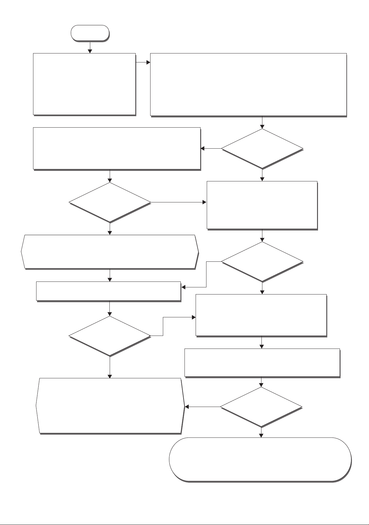
Start
Set Boiler to Maximum Gas Rate
In accordance with boiler instructions,
Insert analyser probe into air inlet test point (where available) and allow
Carry Out Flue Integrity Check Using Analyser
set boiler to operate at maximum rate
(full load condition). Allow sufficient
time for combustion to stabilise.
Note. Do not insert analyser probe
during this period to avoid possible
flooding of sensor.
Note. Where no air inlet test point is provided then a flue integrity check with
the analyser is not possible. The installer should verify that flue integrity has
been visually checked in accordance with the “Prior to CO level and
combustion ratio check” (see opposite page) before proceeding to the
“check CO level and combustion ratio at maximum rate” stage below.
Verify Flue Integrity
Analyser readings indicate that combustion products and inlet air
must be mixing. Further investigation of the flue is therefore required.
Check that flue components are assembled, fixed and supported as
per instructions. Check that flue and flue terminal are not obstructed.
Is
2 more than or
O
equal to 20.6% OR CO
2
Yes
less than or equal to
0.2%?
No
readings to stabilise.
Is
No
O2 more than or
equal to 20.6% OR CO
2
less than or equal to
0.2%?
Yes
Check CO level and Combustion Ratio
at Maximum Gas Rate
With boiler still set at maximum gas rate,
insert analyser probe into flue gas
sampling point. Allow readings to stabilise
before recording.
Turn off appliance and call Ideal Technical Helpline for advice
The appliance must not be commissioned until problems are identified
and resolved. If commissioning cannot be fully completed, the appliance
must be disconnected from the gas supply in accordance with GSIUR.
Check that no seals, e.g. Those on flue extensions, have
been displaced during installation. Rectify if necessary.
Is
CO level less
than 350ppm AND CO/CO
Yes
2
In accordance with boiler instructions, set boiler to
operate at minimum rate (to minimum load condition).
ratio less than
0.0040?
Check CO and Combustion Ratio at Minimum Gas Rate
No
With boiler set at minimum rate, insert analyser probe into flue
gas sampling point. Allow readings to stabilise before recording.
Turn off Appliance and Call Ideal Technical Helpline
The appliance must not be commissioned until problems
are identified and resolved. If commissioning cannot be
fully completed, the appliance must be disconnected from
No
the gas supply in accordance with GS(I&U)R. NOTE:
Check and record CO level and combustion ratio at both
maximum AND minimum rate before contacting Ideal.
Is
No
CO level less
than 350ppm AND CO/CO
2
ratio less than
0.0040?
Yes
Set Boiler to Minimum Gas Rate
(*see opposite page)
Allow sufficient time for combustion to stabilise.
Is
CO level less
than 350ppm AND CO/CO
2
ratio less than
0.0040?
Yes
Installation and Servicing
Boiler is Operating Satisfactorily
No further actions required.
Ensure test points are capped, boiler case is correctly replaced and all
other commissioning procedures are completed. Complete Benchmark
Checklist, recording CO and combustion ratio readings as required.
63
Page 64

Keston pursues a policy of continuing improvement in the design and performance of its products.
The right is therefore reserved to vary specification without notice.
Keston Heating, PO Box 103, National Avenue,Kingston Upon Hull, HU5 4JN
Tel +44 (0) 1482 443005 Fax 44 (0) 1482 467133
Consumer Helpline: +44 (0) 1482 498660
www.keston.co.uk
 Loading...