


Heat 45kw

User Instructions
FAN POWERED HIGH EFFICIENCY
MODULATING CONDENSING
GAS BOILER
CE/PI No. 86-CN-69
Heat 45 - GC No. 41-930-40
Heat 55 - GC No. 41-930-41
Heat 45 & 55
These instructions must be left either with the
user or next to the site gas meter.
Keston Heating
PO Box 103, National Avenue, Kingston Upon Hull, HU5 4JN
Tel. +44 (0) 1482 443005 Fax. +44 (0) 1482 467133
email : info@keston.co.uk web : www.keston.co.uk
COMPLIANT WITH BUILDING REGULATION PART L1 & L2
SEDBUK A RATED
2
Keston Heat - User’s
CAUTION.
To avoid the possibility of injury during the installation, servicing or cleaning of
this appliance care should be taken when handling edges of sheet steel components.
All Gas Safe Registered Engineers carry a Gas Safe Register ID card, and have a registration number.
Both should be recorded in your Log Book. You can check your installer by calling Gas Safe Register direct on 0800 4085500.
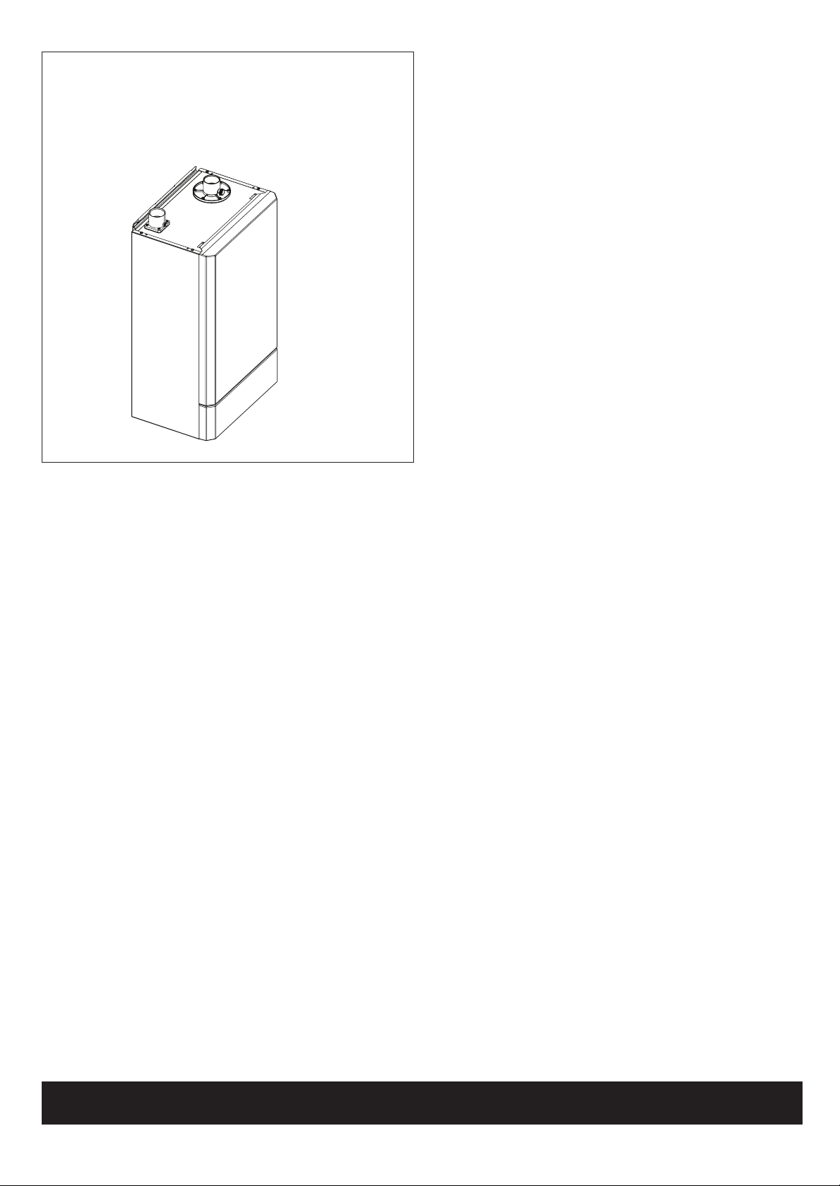
Introduction
The Keston Heat is a wall mounted, room sealed, super efcient
condensing boiler featuring full sequence automatic spark ignition
and fan assisted combustion.
Due to the very high efciency, condensate is produced from the
ue gases and this is drained to a suitable disposal point through
the plastic waste pipe at the bottom of the boiler. A condensate
‘plume’ will also often be visible at the ue terminal.
Safety
Current Gas Safety (Installation & Use)
Regulations or rules in force.
In your own interest, and that of safety, it is the law that this boiler
must be installed and maintained by a Gas Safe Registered
Engineer or in IE a competent person, in accordance with the
above regulations.
The appliance should be serviced at least once a year by a Gas
Safe Registered Engineer or in IE a competent person.
It is essential that the instructions in this booklet are strictly
followed, for safe and economical operation of the boiler.
Electricity Supply
The appliance must be earthed.
Supply 230 V - 50 Hz. The fusing should be 5A.
This appliance is intended to be connected to the supply via a
double-pole switch, having a 3mm contact separation in both
poles, serving only the boiler and system controls. Alternatively, a
3-pin UNSWITCHED socket may be used.
Important Notes
• This appliance must not be operated without
the casing correctly tted and forming an adequate seal.
• If the boiler is installed in a compartment then the
compartment MUST NOT be used for storage purposes.
• Do not store objects around or on the boiler, and keep access
clear at all times.
• Do not obstruct ventilation ducts, grilles or openings in the
boiler room, room space or compartment that the appliance is
installed in, or the passage of combustion and ventilation to
the boiler.
• Do not turn off the boiler if it is to be left unattended in frosty
weather.
• If it is known or suspected that a fault exists on the boiler then
it MUST NOT BE USED until the fault has been corrected by a
Gas Safe Registered Engineer or in IE a competent person.
• Flammable materials must not be placed in close proximity to
the appliance. Materials giving off ammable vapours must not
be stored in the same room as the appliance.
• This appliance can be used by children aged from 8 years
and above and persons with reduced physical, sensory or
mental capabilities or lack of experience and knowledge if they
have been given supervision or instruction concerning use
of the appliance in a safe way and understand the hazards
involved. Children shall not play with the appliance. Cleaning
and user maintenance shall not be made by children without
supervision
In cases of repeated or continuous shutdown a Gas Safe
Registered Engineer or in IE a competent person should be called
to investigate and rectify the condition causing this and carry out
an operational test after each intervention on the device. Only the
manufacturers original parts should be used for replacement.
Minimum Clearances
Clearances of 300mm (12”) below, 25mm (1”) at the sides and
450mm (17 3/4”) at the front of the boiler casing must be allowed
for servicing.
To light the boiler (Refer to Frame 1)
1. CHECK THAT THE ELECTRICITY SUPPLY TO THE BOILER
IS OFF.
2. Set the boiler to standby.
3. Switch on the electricity supply to the boiler and check that all
external controls, e.g. programmer, room thermostat, etc are
on. Allow the boiler to carry out a self check.
4. Set the boiler to winter.
The boiler will commence the ignition sequence, supplying heat to
the system when required.
Keston Heat
45 & 55
Natural Gas
PI No. 86 CN 69
Destination Countries: GB, IE, RO
3
Keston Heat -
User’s
1
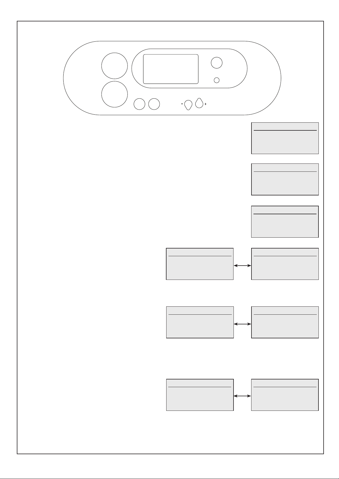
BOILER CONTROLS / DISPLAY
SELECT
2nd STAT
1st STAT
ENTER CHANGE
BURNER ON
RESET
Standby Mode
For Central Heating
select Winter Mode
For Hot Water
select Summer or Winter
Standby Mode
If the boiler has been switched to Standby Mode the following screen will be displayed
No Boiler operation will take place with this setting. See Frame 36 to change to Summer or Winter
setting
Summer Mode
For Central Heating
select Winter Mode
No Hot Water Demand
Switched Live Off
Summer Mode
If the boiler has been switched to Summer Mode a screen similar to the following will be displayed
(line 5 may vary depending on setup)
Domestic Hot Water operation will take place with this setting but Central Heating will not.
See Frame 36 to enable Central Heating by changing to Winter setting
Winter Mode
No Central Heating
Demand
No Hot Water Demand
Switched Live Off
Winter Mode
If there is no current Heat Demand a screen similar to the following will be displayed (line 5 may vary
depending on setup)
Line 5 indicates “Switched Live” or “OpenTherm” or “0-10V” depending on which controls are
connected to the boiler
DHW 230V Operation
Switched Live 2 On
Burner On
DHW Thermostat
Flow Temp 80°C
Domestic Hot Water Mode (DHW Thermostat)
If there is an ongoing Domestic Hot Water Demand using a DHW
Thermostat screens similar to the following will be displayed
Line 2 indicates whether Switched Live or OpenTherm is
controlling the boiler
Line 3 indicates the current operating State (Pre-Purge or Ignition
or Burner On or Pump Overrun)
Burner Power and Flow Temperature will vary as the boiler
operates
DHW 230V Operation
Burner Power 100%
Burner On
DHW Thermostat
Flow Temp 80°C
CH 230V Operation
CH Switched Live On
Burner On
Flow Setpoint 80°C
Flow Temp 80°C
Central Heating Mode
If there is an ongoing Central Heating Demand screens similar to
the following will be displayed
Line 2 indicates whether Switched Live or OpenTherm is
controlling the boiler
Line 3 indicates the current operating State (Pre-Purge or Ignition
or Burner On or Pump Overrun)
Outside temperature will only be shown if an outside sensor is
connected to the boiler
Burner Power and Flow Temp will vary as the boiler operates
See Frame 36 for adjusting Flow Setpoint
CH 230V Operation
Burner Power 100%
Outside Temp’ 10°C
Flow Setpoint 80°C
Flow Temp 80°C
Boiler Frost Protection Mode
If the boiler ow temperature drops below 5°C screens similar
to the following will be displayed
Line 3 indicates the current operating State (Pre-Purge or
Ignition or Burner On or Pump Overrun)
Outside temperature will only be shown if an outside sensor
is connected to the boiler
Burner Power and Flow Temp will vary as the boiler operates
Boiler Frost Protect
Burner Power 100%
Outside Temp’ 10°C
Frost Setpoint 5°C
Flow Temp 80°C
Boiler Frost Protect
Burner Power 100%
Burner On
Frost Setpoint 5°C
Flow Temp 80°C
 Loading...