


Qudos 28s
User, Installation and Servicing
Instructions
FAN POWERED HIGH EFFICIENCY MODULATING DOMESTIC CONDENSING GAS SYSTEM BOILER
CE/PI No. 86-CM-43
Qudos 28s - GC No. 41-930-17
Qudos 28sP - GC No. 41-930-18
These instructions must be left either with the user or next to the site gas meter.
Keston Heating
PO Box 103, National Avenue, Kingston Upon Hull, HU5 4JN
Tel. +44 (0) 1482 443005 Fax. +44 (0) 1482 467133 email : info@keston.co.uk web : www.keston.co.uk
COMPLIANT WITH BUILDING REGULATION PART L1 & L2
SEDBUK A RATED
W D 4 2 0
i s s u e 7 - 2 0 1 1

WD420/3/2007 |
The Keston Qudos 28s & Qudos 28sP Boilers |
|
|
CONTENTS
NB : These instructions are an integral part of the appliance. This document must be handed over to the user on completion of the installation to ensure compliance with the Gas Safety (Installation & Use) Regulations.
Section |
Description |
0 |
HANDLING INSTRUCTIONS |
0.1 |
List of contents |
0.2 |
Recommended handling procedure |
1 |
USER INSTRUCTIONS |
1.1 |
Introduction |
1.2 |
Maintenance |
1.3 |
Boiler Setup and Operation |
1.4 |
Safety Information |
2 |
GENERAL INSTRUCTION |
2.1 |
Description |
2.2 |
Boiler Schematic |
2.3 |
Related Documents |
2.4 |
Physical Data |
2.5 |
Optional Accessories |
2.6 |
Performance Data |
3 |
BOILER LOCATION |
3.1 |
Dimensions & Minimum Clearances |
3.2 |
Service Connections |
3.3 |
Position |
3.4 |
Electrical |
3.5 |
Boiler Size Selection |
3.6 |
Gas Supply |
3.7 |
Water Systems |
3.8 |
Flue System |
3.9 |
Air Supply |
3.10 |
Compartment Installation |
3.11 |
Condensate Drainage |
4 |
INSTALLATION OF THE BOILER |
4.1 |
Wall Mounting Bracket |
4.2 |
Mounting The Boiler |
4.3 |
Assembly Practice |
4.4 |
Installing Flue And Air Pipes |
4.5 |
Condensate Drainage |
4.6 |
Water System |
4.7 |
Gas Supply |
4.8 |
Electrical Supply |
4.9 |
Exchanging A Boiler |
5 |
COMMISSIONING OF THE BOILER |
5.1 |
Initial Flushing |
5.2 |
Gas Supply |
5.3 |
Electrical Installation |
5.4 |
LP Gas |
5.5 |
Initial Firing |
Page : i

WD420/3/2007 |
|
The Keston Qudos 28s & Qudos 28sP Boilers |
|
|
|
5.6 |
|
Hot Flushing |
5.7 |
|
Combustion Testing |
5.8 |
|
Checking the Gas Pressure |
5.9 |
|
Timing The Gas Meter |
5.10 |
|
Handing Over To The User |
6 |
FAULT FINDING |
|
6.1 |
|
Electrical Control Sequence |
6.2 |
|
Normal Operation |
6.3 |
|
Fault Modes |
6.4 |
|
Functional Flow Wiring Diagram |
6.5 |
|
Electrical Wiring Diagram |
6.6 |
|
Illustrated Wiring Diagram |
6.7 |
|
Exploded Assembly Diagrams |
7 |
SERVICING |
|
7.1 |
|
Pre Service Checks |
7.2 |
|
Recommended Routine Service |
8 |
REPLACEMENT OF PARTS |
|
8.0 |
|
General |
8.1 |
|
Precautions |
8.2 |
|
Access |
8.3 |
|
Replacement Procedure |
8.4 |
|
Electrical Components |
8.5 |
|
Spark Ignition/Flame Detection Electrode |
8.6 |
|
Burner |
8.7 |
|
Heat Exchanger |
8.8 |
|
Condensate Trap |
8.9 |
|
Pump |
8.10 |
|
Expansion Vessel |
9 |
SPARE PARTS LISTINGS |
|
10 |
GAS BOILER COMMISSIONING CHECKLIST |
|
Page : ii

WD420/3/2007 |
The Keston Qudos 28s & Qudos 28sP Boilers |
|
|
0. HANDLING INSTRUCTIONS
0.1LIST OF CONTENTS
The Keston Qudos 28s and Qudos 28sP are supplied almost totally pre-assembled. The units use standard 50 mm muPVC (BS5255 and/or BSEN1566-1 and BSEN1329) pipe for the flue and air intake systems. The boiler is packed in a single box without additional flue kit. All additional components are packed inside the boiler cabinet itself. The following is a list of components and their location in the boiler cabinet
Equipment List |
|
|
Item |
Quantity |
Location |
Wall Bracket Rawl Plugs |
6 |
Inside accessories bag |
Wall Bracket Wall Fixing Screws |
6 |
Inside accessories bag |
Wall Mounting Bracket |
1 |
Secured to inside right |
|
|
hand side of boiler case |
Wall Mounting Bracket Nuts |
1 |
Inside accessories bag. |
Wall Mounting Bracket Washers |
1+1 |
Inside accessories bag |
Wall Bracket Bolt Insulation |
1 |
Inside accessories bag |
50 mm muPVC Air/Flue Terminals |
2 |
Inside accessories bag |
Air Inlet Spigot (50 mm) |
1 |
Inside accessories bag |
Flue Outlet Spigot (50 mm) |
1 |
Inside accessories bag |
Air Inlet Spigot Gasket |
1 |
Inside accessories bag |
Air Inlet Spigot + Flue Outlet Spigot M6 Screws |
4+2 |
Inside accessories bag |
Cabinet Cable Entry Clamps |
2 |
Inside accessories bag |
Gas Isolating Cock |
1 |
Inside accessories bag |
Condensate Trap |
1 |
Inside accessories bag |
Condensate Trap fixing screws |
2 |
Inside accessories bag |
Condensate Trap fixing washers |
2 |
Inside accessories bag |
Condensate Trap Gasket |
1 |
Inside accessories bag |
Outside Temperature Sensor |
1 |
Inside accessories bag |
50 mm muPVC Pipe |
2 |
Inside boiler case |
50 mm muPVC Elbow |
2 |
Inside boiler case |
Document List |
|
|
Item |
Quantity |
Location |
Boiler Warranty Registration Form |
1 |
In document bag |
Installation Template |
1 |
In document bag |
Remove the cabinet shell by removing the two retaining screws in the top of the cabinet and the two retaining screws in the bottom of the cabinet.
0.2RECOMMENDED HANDLING PROCEDURE
NB : The following lift operation exceeds the recommended weight for a one-man lift as specified in the Manual Handling Operations 1992 Regulations.
For the carriage of carton it is recommended at least two people perform any lift. Clear the carriage route of the carton from point of delivery to point of installation. Take care to avoid trip hazards, slippery or wet surfaces and when climbing steps and stairs. Always use assistance if required. If a sack truck is used it is recommended the carton is strapped to the truck.
For the unpacking of the appliance from the carton, it is recommended at least two people perform any lift. It is recommended to cut the base end of carton and open the carton flaps. Ensure the protective packing over the boiler tappings at the base of the boiler is kept in place, then tilt the boiler forwards from its back onto its base and remove carton by sliding up over the boiler. When lifting this appliance the back should be kept straight at all times. Avoid
Page : iii

WD420/3/2007 |
The Keston Qudos 28s & Qudos 28sP Boilers |
|
|
twisting at the waist - reposition the feet instead. Avoid upper body bending when holding the appliance and keep the boiler as close to the body as possible.
Before hanging the appliance on the wall it is best to store the appliance laid on its back with the casing on. When ready to hang the boiler on the wall remove the casing and place to one side. At this stage it is assumed that the wall bracket is correctly positioned and secured on the wall face.
a)Have the wall bracket nut and washers to hand so that they can be accessed whilst holding the boiler in position on its mounting bracket.
b)The boiler has a dry weight of 43 kg (95 lbs) and will therefore require at least two people to lift without the use of lifting aids - ensure co-ordinated movements during lift. Always use assistance if required.
c)Lift the boiler by gripping at the four corners of the boiler back plate. When lifting this appliance the back should be kept straight at all times. Avoid twisting at the waist - reposition the feet instead. Avoid upper body bending when holding the appliance and keep the boiler as close to the body as possible.
d)Lift the boiler and locate onto the stud and the two pegs of the wall mounting bracket.
e)Place the wall mounting bracket washers over the bracket stud protruding through the back plate of the boiler.
f)Secure the boiler onto the wall bracket by fixing the wall mounting bracket nut onto the wall bracket stud. This must be tightened well.
Safety footwear and gloves are recommended PPE when lifting this appliance - to protect against sharp edges and ensure good grip.
The Qudos 28s and Qudos 28sP boilers can be fitted in compartments with very small clearances required around the appliance (refer to Section 3.1). Due consideration should therefore be given to access within the compartment for lifting and positioning.
Page : iv

WD420/3/2007 |
Chapter 1 : User Instructions |
The Keston Qudos 28s & Qudos 28sP Boilers |
|
|
|
|
|
1. USER INSTRUCTIONS
1.1INTRODUCTION
Thank you for choosing this Keston Qudos 28s for your household heating. The boiler is designed to be very straightforward to operate and has no user serviceable parts inside the cabinet. The following instructions are to provide you with information on the operation and maintenance of your Qudos 28s and what to do in the unlikely event of a fault.
These user instructions should be read carefully to ensure safe and economical use of your Qudos 28s or Qudos 28sP. The Qudos 28s model is for use with natural gas only, the Qudos 28sP model is for use with LPG only.
1.2MAINTENANCE Servicing
To ensure continual safe and efficient operation and to maintain product warranties it is a requirement that the appliance is checked and serviced at least once per year. It is the law that any servicing must be carried out by a competent person. Removal of the appliance cabinet by anyone other than a competent person will automatically invalidate the appliance warranty.
Clearances
If fixtures are to be positioned close to the boiler, the following minimum clearances must be observed: Top 150mm, Left 5mm, Right 5mm, Base 200mm, Front 10mm. Extended clearance is required to the front for servicing (300mm).
Cleaning
Normal case cleaning only requires dusting with a dry cloth. To remove more stubborn marks wipe with a damp cloth and finish with a dry cloth.
1.3BOILER SETUP & OPERATION
Check that the gas supply from the gas meter is turned on. Switch on the electrical supply to the boiler. The display will now run through a self check procedure. Set any controls to call for heat.
To light the boiler
The Qudos 28s features two temperature controls to allow different settings depending on the source of the demand, i.e. heating or hot water. Identify which setting is demanded. Using the “ ” on the left of the display, select the setpoint you wish to adjust, generally the one indicated by a radiator symbol with a “1” to the left. Set the required temperature using the “+” or “-” buttons associated with the heating zones or hot water temperature. After the selection of the desired temperatures press ENTER and then preset “RESET” to return to the normal display.
If the actual temperature is less than the desired temperature the boiler will fire and, after a few seconds, a “flame” will appear on the display to show that the boiler is alight.
NB: Where the demand is via 0-10VDC or Opentherm the boiler setpoint is set using the external controller in use.
Installation & Servicing Instructions |
Page : 1 |

WD420/3/2007 |
Chapter 1 : User Instructions |
The Keston Qudos 28s & Qudos 28sP Boilers |
|
|
|
|
|
Normal Operation
During normal operation the digital display will show the current boiler temperature and will show relevant operational symbols to confirm what action the boiler is taking. If the “radiator”,
or “ ” symbol is shown on the display the boiler is receiving a demand for that function.
Fault Modes
In the event that the boiler detects a situation which it considers to be a fault the display will change to show a flashing fault code starting with an “E” and then a two digit number. The table below explains these codes and the action you should take.
Display |
Description of fault |
E02 |
Ignition lockout - the boiler has attempted to light five times and not succeeded - check |
|
the gas supply is on. |
E04 |
Flame failure whilst running - the boiler is having difficulty maintaining the flame. |
|
Consult your Service Engineer and check for flue, gas supply or condensate drainage |
|
obstruction |
E12 |
Flow overheat - the boiler has exceeded it maximum water temperature. Check that any |
|
by-pass is open and the controls are operating correctly |
E26 or |
The system water pressure is too low. Check the system has water in and, for sealed |
E67 |
systems, top up the system water pressure to restore a pressure of between 1 and 2 |
|
bar. (Consult your installer for instruction how to top up water pressure - repeated need |
|
for restoration of water pressure indicates a system leak which should be investigated) |
E25 |
The boiler temperature is rising too fast - ask your Service Engineer to check for |
|
system blockage or pump failure. |
E52 |
The flue temperature is too high. Consult your Service Engineer - SERVICE RESET |
|
REQUIRED |
E62 |
Water pressure too high - check that the system water pressure top-up valve has not |
|
been left open or consult your installer to check the expansion vessel. |
E70 |
The cabinet has overheated - consult your Service Engineer before operating the boiler |
|
further - SERVICE RESET REQUIRED |
The above is an abbreviated list of possible error codes. If the code is not in the list above consult a GAS SAFE REGISTER registered engineer. A full list of codes can be found in Chapter 6 of this manual. If a code appears and you feel the original cause has been rectified and it has not been designated as requiring a “Service Reset”, press the “Reset” button to resume boiler operation. Otherwise, or if the code persists consult a GAS SAFE REGISTER registered engineer.
Raise up the system pressure until error E67 or E26 disappears from display (the boiler will enter in standby mode or will start to fire up if a heat demand exists). To check the system pressure press the “ ” button repeatedly until the display shows the water pressure, indicated by the word “bar” to the right of the number. To return to main screen press the RESET button.
Precautions
Care must be taken at all times to ensure that no blockage or obstruction is present in the condensate drainage line. In addition, the air intake and flue exhaust terminals must be free from obstruction at all times.
Care should be taken not to damage the condensate trap protruding from the base of the boiler. Any sign of leakage of this part should be reported to a GAS SAFE REGISTER registered engineer immediately. If the part becomes broken the boiler should be turned off and a GAS SAFE REGISTER registered engineer contacted to make a repair.
Any indication of leakage from the boiler cabinet should be investigates by a GAS SAFE REGISTER engineer.
Frost Protection
The Qudos 28s has an integral frost protection function. However, care should also be taken that any exposed pipework is adequately insulated to prevent freezing.
Installation & Servicing Instructions |
Page : 2 |

WD420/3/2007 |
Chapter 1 : User Instructions |
The Keston Qudos 28s & Qudos 28sP Boilers |
|
|
|
|
|
1.4SAFETY INFORMATION
IF YOU SUSPECT A GAS LEAK TURN OFF THE APPLIANCE IMMEDIATELY, TURN OFF THE GAS TAP TO THE APPLIANCE (LOCATED UNDERNEATH) AND CONTACT YOUR GAS SUPPLIER WITHOUT DELAY.
Benchmark Initiative
As part of the industry wide “Benchmark” initiative Qudos 28 boiler manual includes Gas Boiler Commissioning
Checklist (Chapter 10). This form should be completed by your installer at the end of the installation and commissioning process. The details of the Checklist will be required in the event of any warranty work being required. There is also Service Interval Record (Chapter 10) to be completed after each annual service visit.
These forms (Chapter 10) should be kept in a safe place for the life of the boiler.
The boiler should be installed and serviced only by GAS SAFE REGISTER registered operatives. All GAS SAFE REGISTER registered Installers carry a GAS SAFE REGISTER ID card and have a registration number. Both should be recorded in your boiler manual (Chapter 10: GAS BOILER COMMISSIONING CHECKLIST). You can check your installer by calling GAS SAFE REGISTER direct on 0800 408 5500.
IMPORTANT
This appliance is not intended for use by persons (including children) with reduced physical, sensory or mental capabilities, or lack of experience and knowledge, unless they have been given supervision or instruction concerning use of the appliance by a person responsible for their safety.
Children should be supervised to ensure that they do not play with the appliance.
Installation & Servicing Instructions |
Page : 3 |

WD420/3/2007 Chapter 2 : General Instruction The Keston Qudos 28s & Qudos 28sP Boilers
2. GENERAL INSTRUCTION
2.1DESCRIPTION
The KESTON Qudos 28s and Qudos 28sP boilers utilize the latest in condensing technology to produce a high efficiency boiler with SEDBUK A rated efficiency plus advance controls to maximize operational efficiency.
The Qudos 28s is unique in concept and design. It comprises a high efficiency stainless steel heat exchanger coupled with a low emissions burner to deliver ultra high efficiency condensing mode operation within a compact wall hung cabinet. The unit automatically adjusts gas and air rate according to demand to give a heating input in the range of 7.8kW to 29.4kW (GCV). The integral pump assembly, in the Qudos 28s, is automatically speed controlled to best match water flow rate to heat output & further increase appliance efficiency.
The Qudos 28s has been developed to embrace the concept of advanced controls to ensure the ultra high performance burner and heat exchanger system is run to optimum performance levels whilst provided or exceeding the comfort levels demanded. As a result the boilers feature a host of additional connections for:
-an optional outside sensor to enable the boilers inbuilt weather compensation option which delivers enhanced user comfort levels with peak operating efficiency due to the lower flow temperatures involved.
-an optional “Opentherm” connection point for the Keston Room Control module which provides further advanced user control for room temperature compensation and optimum start.
-optional 0-10VDC input where temperature control is provided by external 3rd party intelligent controls
-optional connection of a DHW thermistor to enable modulated reheat of DHW and optional legionella prevention function
Further, the Qudos 28s is developed with the concept that the gas boiler in the modern home is often supplemented by alternative or renewable energy sources. As a result the Qudos 28s features:
- optional connection of a solar thermal system, pump, panel and DHW sensor, for direct control of solar thermal system from the boiler. Other additional energy source systems, such as Ground Source Heat Pump, will be accommodated soon.
The boilers have the added advantage of very high efficiency, and small diameter muPVC plastic flue which can be extended up to 20 metres horizontally or vertically.
The Keston Qudos 28s uses a variable speed combustion blower to deliver a premix of gas and air to a downward firing burner in a high efficiency, single pass heat exchanger. The flue system is room sealed and fan powered. The ignition is direct spark and fully automatic. The boiler housing is not waterproof and should be installed in a position where it will always be dry. Combustion air is drawn from the cabinet which is connected to outside atmosphere via a small diameter plastic intake pipe. The cabinet therefore remains under negative pressure at all times the boiler is operating.
These boilers are designed for use as part of a sealed water central heating system with fully pumped circulation. The pump, an 8l expansion vessel and associated safety devices are all fitted within the Qudos 28s boiler. However, consideration should be given to additional expansion vessels on larger systems where 8 litres may be inadequate.
Installation & Servicing Instructions |
Page : 4 |

WD420/3/2007 |
Chapter 2 : General Instruction |
The Keston Qudos 28s & Qudos 28sP Boilers |
|
|
|
|
|
ENTER |
RESET |
The boiler heat exchanger is made from highly corrosion resistant stainless steel in corrugated pipe form which provides massive surface area within a compact dimension. The hot combustion gases from the down firing burner pass around the stainless steel pipes imparting heat into the system water. On the Qudos 28s integral variable speed pump within the appliance cabinet ensures the heat exchanger receives correct water flow when firing. The Qudos 28s is not a high water content boiler and does not contain the metal mass, or water volume, of a cast iron or steel boiler. This boiler is of low mass and low water content and therefore responds faster when there is a call for heat. The Qudos 28 features full user diagnostics, integral frost protection function, automatic pump and fan exercise in periods of inactivity, anti cycle control and dry fire protection.
2.2BOILER SCHEMATIC
Air is drawn into the boiler through a 50 mm muPVC (BS5255 and/or BSEN1566-1 and BSEN1329) plastic pipe or, alternatively, via a 75mm Keston composite plastic pipe. Gas is mixed with combustion air at the inlet to the fan. The gas flow is automatically regulated by the gas valve according to the air flow generated by the fan. The gas and air are thoroughly mixed in the blower and fed into the burner located at the top end of the heat exchanger module. The gas and air mixture is ignited by a direct spark ignition control system and burns with a blue flame just off the surface of the burner. As the hot products of combustion pass downwards, they are cooled by exchanging heat with the circulating water which enters the heat exchanger at the bottom of the heat exchanger. The optimum heat input is detected by monitoring flow and return temperatures and is adjusted by controlling the speed of the fan. The optimum pump speed is also detected and automatically selected by the boiler.
When the return water temperature is below 55oC, part of the water vapour in the combustion products will condense inside the heat exchanger, thus increasing the boiler efficiency further by releasing the latent heat of condensation. This condensate falls to the
Installation & Servicing Instructions |
Page : 5 |
WD420/3/2007 Chapter 2 : General Instruction The Keston Qudos 28s & Qudos 28sP Boilers
bottom of the heat exchanger where it is separated from the flue gases and exits from the boiler through the condensate drain. Any condensate formed in the flue runs back down the flueway and is drained at the base of the flue connection to the heat exchanger or drain points within the flue.
The condensate is very slightly acidic (about the same acidity as vinegar) and should be piped in a plastic pipe. It is not harmful to the waste disposal system and may be disposed of as normal waste water.
The flue gases are piped in a 50 mm muPVC (BS5255 and/or and BSEN1329) plastic or, alternatively, 75mm Keston composite plastic pipe to outside. The temperature of the flue gases are usually around 5oC to 10oC above the temperature of the return water. The flue pipe should be terminated outside the building from where they cannot re-enter the building or any other adjacent building. It should also be terminated such that flue products cannot be drawn into the boiler air intake terminal.
The heating level may be controlled by room thermostats, programmer time clocks and compatible energy management systems. An optional Keston room controller can be connected which will provide enhanced controls such as room compensation to further increase efficiency and comfort levels. However, this is only recommended for heating only applications. Once the controls are set the boiler operates automatically. Further, a Keston outside sensor can be connected to the boiler which will automatically invoke weather compensated heating which further boosts user comfort and boiler efficiency.
In the event of the boiler overheating the safety devices will cause a safety shutdown. A safety discharge valve and discharge pipe is fitted to the boiler.
The Qudos 28s features an integral frost protection function which will operate the pump, regardless of the external controls, should the boiler temperature fall below 10oC. In the event the boiler temperature falls below 5oC the boiler will also fire. This is to avoid damage to the boiler through freezing of boiler water. The boiler will turn off when the flow temperature exceeds 15oC.
The Qudos 28s features an integral pump exercise function which will run the pump, without
Installation & Servicing Instructions |
Page : 6 |

WD420/3/2007 |
Chapter 2 : General Instruction |
The Keston Qudos 28s & Qudos 28sP Boilers |
|
|
|
|
|
firing the boiler, for 10 seconds in the event the boiler is on standby for in excess of 24 hours without firing. This is to help prevent seizing of the pump due to long periods of inactivity.
2.3RELATED DOCUMENTS
The Keston Qudos 28s and Qudos 28sP Condensing Boilers must be installed in accordance with the current issue of the Gas Safety (Installation and Use) Regulations 1996, current IEE Wiring Regulations, Building Regulations, Building Standards (Scotland) Consolidation, and the Bye Laws of the local Water Undertaking. It is the law that ALL gas appliances are installed by a competent person in accordance with the above regulations.
In addition, due account must be taken to the following Codes Of Practice:
BS 6891 |
: |
Low Pressure Installation Pipes |
BS 6798 |
: |
Installation of Gas Fired Hot Water Boilers of |
|
|
Rated Input Not Exceeding 70kW |
BS 5449 |
: |
Installation Pumped Central Heating |
BS 5546 |
: |
Installation of Gas Hot Water Supplies for |
|
|
Domestic Purposes (2nd family gases) |
BS 5440.1 |
: |
Flues (for gas appliances of rated input not |
|
|
exceeding 70kW) |
BS 5440.2 |
: |
Air Supply (for gas appliances of rated input not |
|
|
exceeding 70kW) |
BS 5482.1 |
: |
Domestic Propane and Butane Burning |
|
|
Installations |
BS 7074.1 |
: |
Expansion Vessels |
BS 7593 |
: |
Treatment of Water in Hot Water Central Heating |
|
|
Systems |
BS 7671 |
: |
Requirements for Electrical Installations. IEE |
|
|
Wiring Regulations 16th Edition. |
BSEN 12828:2003 |
: |
Heating Systems in Buildings: Design for water |
|
|
based heating systems |
BSEN 12831:2003 |
: |
Heating Systems in Buildings: Method for |
|
|
calculation of design heat load |
BSEN 14336:2004 |
: |
Heating Systems in Buildings: Installation and |
|
|
commissioning of water based heating systems |
For Timber Framed Buildings, British Gas Publications DM2. Also British Gas Publications 'Guidance Notes For The Installation Of Domestic Gas Condensing Boilers' and 'Specification For Domestic Wet Central Heating Systems'.
In IE, the installation must be carried out by a competent person and installed in accordance with the current edition of IS813 “Domestic Gas Installations”, the current Building Regulation and reference should be made to the current ETC1 rules for electrical installations.
No alterations should be made to the boiler without written permission from KESTON Heating. Any unauthorised modification will invalidate the warranty and may affect the safe and efficient operation of the boiler.
Installation & Servicing Instructions |
Page : 7 |

WD420/3/2007 Chapter 2 : General Instruction The Keston Qudos 28s & Qudos 28sP Boilers
2.4PHYSICAL DATA - Qudos 28s & Qudos 28sP
Cabinet Height |
mm |
700 |
Cabinet Width |
mm |
435 |
Cabinet Depth |
mm |
280 |
Top Clearance |
mm |
150 |
Side Clearance |
mm |
5 |
Base Clearance |
mm |
200 |
Front Clearance (for servicing) |
mm |
300 |
Weight - Full |
kg / (lbs) |
47/(104) |
Weight - Empty |
kg / (lbs) |
43/(95) |
Flow and Return Connection |
|
G3/4 |
Gas Connection |
|
G1/2 |
Condensate Connection overflow |
|
22mm plastic |
Safety Valve Connection discharge |
|
15mm copper |
IP Rating |
|
IP20 (IPX0) |
Flue and Air Intake Material 50mm muPVC (BS5255 and/or BSEN1566-1 and BSEN1329)
Flue Pipe Size (nominal bore) |
mm / (in) |
50 / (2) |
Air Intake Pipe Size (nominal bore) |
mm / (in) |
50 / (2) |
Max. Air Intake Length |
m |
39 |
Max. Flue Outlet Length |
m |
20 |
Max. Total Flue Outlet and Air Intake Length |
m |
40 |
Flue and Air Intake Material |
75mm Keston Composite |
|
Flue Pipe Size (nominal bore) |
mm / (in) |
75 / (3) |
Air Intake Pipe Size (nominal bore) |
mm / (in) |
75 / (3) |
Max. Air Intake Length |
m |
117 |
Max. Flue Outlet Length |
m |
60 |
Max. Total Flue Outlet and Air Intake Length |
m |
120 |
2.5OPTIONAL ACCESSORIES
A range of accessories are available from KESTON Heating to compliment an installation. Terminal wall sealing collars are available to make good the external all face whilst working from the inside of the building using 50mm muPVC (BS5255 and/or BSEN1566-1 and BSEN1329) pipe. Stand-off frames are available to leave a 50mm gap behind the boiler to allow routing of pipes behind the boiler.
Description |
Part Number |
Flue Terminal Wall Sealing Collar (50mm) |
C.08.0.00.07.0 |
Air Terminal Wall Sealing Collar (50mm) |
C.08.0.00.07.0 |
50/75mm Flue Adapter |
C.17.2.00.60.0 |
Flue Outlet Terminal (75mm) |
C.17.2.26.00.0 |
Air Inlet Terminal (75mm) |
C.17.2.26.00.0 |
Stand Off Back Plate |
Q.10S.0.01.00.0 |
Keston Chronotherm Room Controller |
C.17.4.21.00.0 |
DHW Tank Sensor |
Q.10S.0.04.00.0 |
Solar Sensors Kit (Panel sensor and 2 x DHW Tank Sensors) |
Q.10S.0.05.00.0 |
Installation & Servicing Instructions |
Page : 8 |

WD420/3/2007 |
Chapter 2 : General Instruction |
The Keston Qudos 28s & Qudos 28sP Boilers |
|
|
|
|
|
2.6PERFORMANCE DATA - Qudos 28s & Qudos 28sP
|
|
Qudos 28s |
Qudos 28sP |
|
|
Nat. Gas (G20) |
LPG (G31) |
Min. Input (Gross CV) |
kW/(Btu/h) |
7.8/(26,600) |
7.6/(26,000) |
Max. Input (Gross CV) |
kW/(Btu/h) |
29.4/(100,300) |
28.8/(98,300) |
Max. Output To Water |
|
|
|
(80/60oC Flow/Return) |
kW/(Btu/h) |
26.4(90,500) |
26.4/(90,500) |
(50/30oC Flow/Return) |
kW/(Btu/h) |
28.4/(96,900) |
28.4/(96,900) |
Min. Output To Water |
|
|
|
(80/60oC Flow/Return) |
kW/(Btu/h) |
7.0/(24,900) |
7.0/(24,900) |
(50/30oC Flow/Return) |
kW/(Btu/h) |
7.8/(26,600) |
7.6/(26,000) |
Max. Burner Press.-Hot (Factory Preset) |
mbar/(in w.g) |
0/(0) |
0/(0) |
Max. Gas Cons. After 10 mins (DHW) |
l/s / (Ft3/hr) |
0.76/(96.6) |
0.35/(45.0) |
Max. Operating Flow Temp. |
oC |
82 |
82 |
Max. Press. (Sealed System) |
bar |
2 |
2 |
Inlet Gas Pressure |
mbar/(in w.g) |
20.0 / (8.0) |
37.0/(14.8) |
Recommended Temp Diff. |
oC |
8 to 20 |
8 to 20 |
Electrical Supply |
|
230V 50Hz |
230V 50Hz |
Power Consumption (Max) |
W |
150 |
150 |
Power Consumption (Standby) |
W |
7 |
7 |
Type of Gas |
|
G20 Natural Gas |
G31 LPG |
Optimum Flue Gas CO2 Level (at max CH rate, case on) |
9.1±0.2 |
10.5 ±0.2 |
|
Expected CO/CO2 Ratio (at max CH rate, case on) |
0.0007 |
0.001 |
|
Destination Countries |
|
GB/IE |
GB/IE |
SEDBUK Efficiency |
|
91.0 |
93.0 |
NOx Class |
|
5 |
5 |
Safety Valve |
bar / (lbf/sq in) |
3 / (43.5) |
3 / (43.5) |
Expansion Vessel Capacity |
litre |
8 |
8 |
SEDBUK Rating |
|
A (91.1%) |
A (92.9%) |
[NB: For larger systems an additional expansion vessel may be required] |
|
||
Expansion Vessel Charge Pressure |
bar / (lbf/sq in) |
1.0 / (14.5) |
|
Heating System Minimum Pressure |
bar / (lbf/sq in) |
0.6 / ( 8.7) |
|
|
|
|
|
Seasonal Efficiency (SEDBUK) = 91.1 (Qudos 28s) & 92.9 (Qudos 28sP)
This value is used in the UK Government's Standard Assessment Procedure (SAP) for energy rating of dwellings. The test data from which it has been calculated have been certified by Advantica Technologies Ltd
KESTON Heating declare that there are no substances harmful to health within the appliance or used during the production of the appliance.
The Qudos 28s is intended for domestic and commercial EMC environments and on a governed G20 meter supply.
The Qudos 28sP is intended for domestic and commercial EMC environments and on a governed G31 supply.
This boiler meets the requirements of SI 3083 The Boiler (Efficiency) Regulations and is therefore deemed to meet the requirements of Directive 92/42/EEC. The CE mark on the appliance shows compliance with Directives 90/396/EEC, 73/23/EEC and 89/336/EEC.
IMPORTANT
This product contains ceramic fibre boards, which although not regarded as a risk, contain ceramic fibre which may cause temporary irritation to eyes, skin and respiratory tract. The fibres are held in place by inorganic binders. Therefore as long as the boards are not
Installation & Servicing Instructions |
Page : 9 |

WD420/3/2007 Chapter 2 : General Instruction The Keston Qudos 28s & Qudos 28sP Boilers
disturbed they will not be released. Since the boards are non-serviceable parts there should be no risk. Under no circumstances should the user interfere with any sealed parts. To ensure that the release of fibres from these RCF articles is kept to a minimum, during installation and servicing we recommend that you use a HEPA filtered vacuum to remove any dust accumulated in and around the appliance before and after working on the appliance. When replacing these articles we recommend that the replaced items are not broken up, but are sealed within heavy duty polythene bags, and clearly labelled as RCF waste. RCF waste is classed as a stable, non-reactive hazardous waste and may be disposed at a landfill licensed to accept such waste. Protective clothing is not required when handling these articles, but we recommend you follow the normal hygiene rules of not smoking, eating or drinking in the work area and always wash your hands before eating or drinking.
Benchmark Initiative
As part of the industry wide “Benchmark” initiative Qudos 28S boiler manual includes Gas Boiler Commissioning Checklist (Chapter 10). This form should be completed by your installer at the end of the installation and commissioning process. The details of the Checklist will be required in the event of any warranty work being required. There is also Service Interval Record (Chapter 10) to be completed after each annual service visit.
These forms (Chapter 10) should be kept in a safe place for the life of the boiler.
The boiler should be installed and serviced only by GAS SAFE REGISTER registered operatives. All GAS SAFE REGISTER registered Installers carry a GAS SAFE REGISTER ID card and have a registration number. Both should be recorded in your boiler manual (Chapter 10: GAS BOILER COMMISSIONING CHECKLIST). You can check your installer by calling GAS SAFE REGISTER direct on 0800 408 5500.
IN THE EVENT OF A GAS LEAK
Turn off the gas isolation valve to the property immediately. Extinguish all naked flames or other sources of ignition. Do not operate electrical switches on or off. Open all doors and windows to ventilate the area.
|
|
|
|
|
|
|
|
Installation & Servicing Instructions |
Page : 10 |
||

WD420/3/2007 |
Chapter 3 : Boiler Location |
The Keston Qudos 28s & Qudos 28sP Boilers |
||
|
|
|
|
|
3.BOILER LOCATION
3.1DIMENSIONS AND MINIMUM CLEARANCES
The boiler must be installed in minimum clearances shown to allow subsequent servicing, and safe operation. However, larger clearances may be required during installation.
3.2SERVICE CONNECTIONS
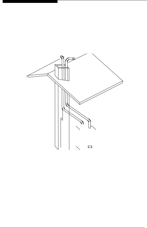
Gas, water, air and flue pipe, condensation, and electrical connections are as shown in the diagram below. Gas : 15mm compression. Flow/Return 0.75 inch BSP male, Gas 0.5 inch BSP male, PRV 15mm copper pipe and Condensate 21.3mm plastic pipe .

|
|

An optional stand-off |
frame |
(part |
number |
|
|
|||
Q.28S.0.01.00.0) |
is |
also |
available |
which |
|
|||
|
|
|||||||
mounts behind the boiler to leave a 50mm |
||||||||
|
|
|||||||
deep space behind the boiler. This is to |
|
|
||||||
permit pipe routing behind the boiler if |
|
|
||||||
required. See |
Section |
2.5 |
- Optional Figure 3.1.2 |
|
|
|||
Accessories. |
|
|
|
|
Dimensions |
|
|
|
3.3 |
POSITION |
|
|
|
The Qudos 28s and Qudos 28sP are not |
|
|
|
suitable for external installation. The boiler |
! |
|
|
may be installed in any room or internal |
|
|
|
space, although particular attention is drawn |
|
|
|
to the requirements of the current IEE Wiring |
|
|
|
Regulations and, in Scotland, the electrical |
|
|
|
provisions of the Building Regulations |
|
|
|
applicable in Scotland, with respect to the |
|
|
|
installation of the boiler in a room or internal |
|
|
|
space containing a bath or shower. |
|
|
|
Where a room-sealed appliance is installed |
|
|
|
in a room containing a bath or shower, any |
2 |
8 |
|
electrical switch or appliance control, utilising |
|
|
|
|
|
|
|
mains electricity, should be so situated that it |
|
|
|
|
|
|
|
cannot be touched by a person using the |
|
|
|
bath or shower. The Qudos 28S and Qudos 28SP are classified as IP20 (IPX0) and are |
||
|
therefore suitable for installation in Zone 3 areas, unless subject to hose down. |
|
|
m
"
0 
Installation & Servicing Instructions |
Page : 11 |
WD420/3/2007 Chapter 3 : Boiler Location The Keston Qudos 28s & Qudos 28sP Boilers
Compartment installation is permitted - such compartments must be constructed in accordance with BS 6798.
The wall on which the boiler is mounted must be of suitable load bearing capacity and must be non-combustible.
The Keston Qudos 28s can be located virtually anywhere desired provided that all regulations are complied with. Because of the boiler's compact size and venting flexibility, the installation is not limited to a boiler room setting. Before locating the boiler near a living space consider whether the sounds generated by the boiler will be objectionable. The boiler may be located within a cupboard enclosure to reduce noise levels if located within
a living space. LPG boilers must not be installed in a cellar.
#$%
#
# &$ ' ( %
#
[NB: Refer to |
|
|
|
|
|
|
||
|
|
|
|
|
||||
|
|
|
|
|
||||
|
|
|
|
|
||||
Section 3.8.3] |
|
|
|
|
|
|||
|
|
|
|
|
|
|||
|
|
|
|
|
|
|
|
|
|
|
|
|
|
|
|
|
|
3.4ELECTRICAL
3.4.1Electrical Connections
The boiler must be connected to a permanent 230V ~ 50Hz supply, fused at 3A.
The boiler can be wired to a single switched live 230VAC signal input. However, the boiler has TWO thermostats, and will therefore accept up to TWO switched live 230VAC signal inputs, such as heating and hot water or radiators and underfloor heating zones. Alternatively, a Keston Room Controller can be connected directly, via two core low voltage cable, to the terminals marked “OT”. The Keston Room Controller will then provide fully room compensated control to ensure the boiler output is matched to the rooms requirements at optimum boiler efficiency. This is only recommended for heating only applications. The boiler can also be driven by an external 0-10VDC input.
Wiring external to the boiler must be in accordance with current I.E.E wiring regulations and local regulations.
The method of connection to the mains electricity supply must facilitate complete electrical isolation of the boiler, preferably by the use of a fused, unswitched three pin plug and a shuttered socket-outlet, both complying with the requirements of
Installation & Servicing Instructions |
Page : 12 |

WD420/3/2007 |
Chapter 3 : Boiler Location |
The Keston Qudos 28s & Qudos 28sP Boilers |
||
|
|
|
|
|
BS 1363. There must be only one common method of isolation for the boiler and its control system.
The appliance must be connected to the 3A supply via a fused double-pole switch having at least 3 mm (1/8 inch) contact separation in both poles, serving only the boiler and the system controls.
The connection point to the mains supply should be readily accessible and adjacent to the boiler, except for rooms containing a bath or a shower. Refer to section 3.3 Position.
3.4.2External Wiring & Controls
1.The boiler is designed so that all control wiring is external to the boiler.
2.Heating control signal inputs must be 230VAC "switched live" type unless using a Keston Room Controller (see below) or 0-10VDC input.
3.4.2.1 Enhanced Control Options
The Qudos 28s can be wired into a conventional heating installation using only permanent and switched live connections.
However, the Qudos 28s features a wide range of OPTIONAL control features normally associated with commercial boilers installations at additional cost. These are provided as standard in the Qudos 28s and require low costs sensors to be added to activate them. The features provided are detailed below. Refer to Chapter 4.8 for further wiring detail.
Room Compensation (Opentherm)
A Keston Room Controller may be used to provide room compensated control to ensure the boiler output is matched to the rooms requirements at optimum boiler efficiency. This is only recommended for heating only applications
Weather Compensation (Ext Sensor)
A Keston outside temperature sensor may be connected as an option. The boiler will automatically detect this connection and will operate on a "weather compensation" basis when receiving a heating demand signal from the SL terminal or from a Keston Room Controller. Screened cable (80% density) must be used to connect the outside temperature sensor.
Solar Control
Where a solar thermal system is in use, with a twin coil cylinder such as the Keston qSpa Twin, the Qudos 28s will control operation of the solar pump in conjunction with the boiler. The boiler requires connection to the solar tank sensor, solar panel sensor and solar pump
Modulating DHW Reheat
The Qudos 28s can provide direct modulation to maximise the re-heat performance of the DHW cylinder. A DHW cylinder sensor can be connected directly to the Qudos 28. A DHW demand input can also be provided to control DHW reheat activity, perhaps in conjunction with Solar Thermal. With this facility connected an automatic anti-legionnella facility can also be provided.
Analog Demand (0-10VDC)
Where external control panels are used, in boiler room applications, a 0-10VDC input can be connected to the boiler, in place of the SL1 switched live demand. The 0-10VDC signal will drive the first setpoint at 1VDC = 10C setpoint (NB: <0.5VDC is off, >8.0 VDC is 80C)
External Lockout Signal
Where remote monitoring and/or alarms are installed the boiler offers a volt-free lockout signal output. The boiler will provide a closed circuit across the two output points when the boiler is in lockout.
Installation & Servicing Instructions |
Page : 13 |

WD420/3/2007 |
Chapter 3 : Boiler Location |
The Keston Qudos 28s & Qudos 28sP Boilers |
||
|
|
|
|
|
3.5BOILER SIZE SELECTION
The Qudos 28s will automatically adjust heat output and pump speed to match the system requirements at any given time. Efficiency and combustion levels are maintained at optimum levels throughout the possible output range. The Qudos 28s is therefore suitable for all systems with a total heat load within the maximum range of the boiler.
3.6GAS SUPPLY
A gas meter should be connected to the service pipe by the local gas region or their contractor. An existing meter should be checked preferably by the gas region to ensure that the meter is adequate to deal with the rate of gas supply required. Installation pipes should be fitted in accordance with BS 6891.
Minimum/Maximum Gas Pressure:
Natural gas pressure before the gas valve must be maintained at between 18 mbar (7.2 in WG) and 22 mbar (8.8 in) while the boiler is running.
LPG pressure must be maintained between 31.5 mbar (12.4 in w.g) and 37.6 mbar (14.8 in w.g) while the boiler is running.
Gas pressures above or below these levels will lead to problems associated with the gas valve's internal pressure regulator.
Supply pipes to the boiler must not be sized less than the boiler inlet connection (15 mm). Due consideration must be given to the supply pressure to other gas appliances in the premises. Reduction in dynamic gas supply pressure will result in intermittent ignition failures. Ensure gas supply pipe work is adequately sized for the length of run from the meter to the boiler at a supply rate of 28.4kW (i.e. a natural gas supply should be considered to be a minimum of 22mm diameter, reducing to 15mm at the boiler. If gas runs greater than 12m, including the allowance for bends, are involved the pipe size should be increased further).
3.7WATER SYSTEMS
All piping must be installed in accordance with all applicable local and Water Supply Bylaws for forced hot water heating systems.
Consideration must be given to pipe capabilities and pressure drop through the piping when selecting pipe sizes. The primary pipe connections to the boiler must be sized according to the system load, not dictated by the boiler connection sizes.
Water treatment must be carried out to BS 7593 : Treatment of Water in Hot Water Central Heating Systems.
In IE the requirements given in the current edition of IS813 and the current Building Regulations must be followed.
a The Keston Qudos 28s is designed for installation on sealed water systems only. With fully pumped water circulation. The pump, an 8l expansion vessel and associated safety devices are fitted within the boiler.
b Any system must be thoroughly flushed clean of grease, dirt and debris, prior to connection with the boiler. A trap may be installed in the flow line to collect any solder, or other debris, from the installation.
c All water systems must be constructed to comply with requirements of the Local Water Authority.
d Always use a system complying with the requirements of BS 5449 and BS 6798. e System design must ensure an open circuit is always available to ensure
circulation when the pump overrun function is operating after boiler shutdown.
f Isolation valves must be fitted on the flow and the return to enable isolation when maintaining the boiler.
Installation & Servicing Instructions |
Page : 14 |
 Loading...