

Page 1

WD435/0/2006 DRAFT2 Keston Solar Thermal
SOLAR THERMAL
SYSTEMS
User, Installation and Servicing
Instructions
These instructions must be left with the
user
Keston Boilers Ltd
34 West Common Road
Hayes, Bromley, Kent BR2 7BX
Tel. +44 (0)20 8462 0262 Fax. +44 (0)20 8462 4459
email : info@keston.co.uk web : www.keston.co.uk
Page 2

WD435/0/2006 DRAFT2 Keston Solar Thermal
CONTENTS
Section Description
0 LIST OF CONTENTS
1 GENERAL INSTRUCTION
2 INSTALLATION
3 COMMISSIONING
4 HANDING OVER TO THE USER
5 ROUTINE SERVICING
6 FAULT FINDING
7 PARTS LIST
Page : i
Page 3
T
1 Collector
R
1 Pump Cable
Flowmeter
SRV
AAV
TMV
CW
HW
DTC
Manometer
Thermometers
Collector
WD
435
/0/2006
Chapter 1 :
General
Instruction
Keston
Solar
Thermal
1.
The Keston Solar Thermal System is a state-of-the-art solar system. It features high
performance collectors with highly advanced features. The collector has been awarded the
Solar Keymark, the EUs quality mark for solar collectors. The collectors are mounted on a
fast-to-fit frame and, for the Solar Packs and Solar Duet, a solar pump station is also
supplied to ease the internal component location. The Keston Solar Controller ensures
efficient use of the available solar energy at any given time and features several extra
functions such as modulating pump speed which further improve system efficiency
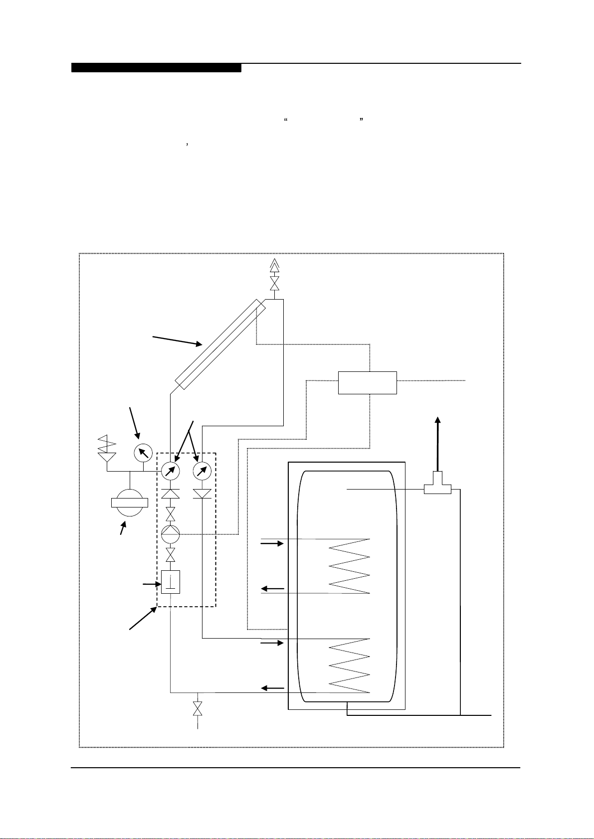
Keston Solar System
General Instruction and Schematic Layout
Recommended
Solar
Hydraulic and Control Circuit Layout
Sensor Cable
230 V Live
Exp
ansion
Vessel
Pump
Station
T
2 Sensor Cable
Boiler
Coil
Solar
Coil
Installation & Servicing Instructions
Page :
1
Page 4
WD
435
/0/2006
Chapter 1 :
General
Instruction
Keston
Solar
Thermal
1.1
Performance Requirements
The Keston Solar System uses a similar hydraulic circuit to a standard system boiler.
However, there are several important differences between these two circuits. A solar circuit
has to manage both freezing and steam conditions in the solar collector.
The freezing is managed by using a suitable solar-grade glycol antifreeze within the circuit
mixed to a suitable ratio for the climatic conditions.
The steam conditions can occur during stagnation . The Differential Temperature Controller
(DTC) has an setting for the maximum temperature of stored (secondary) water in the cylinder (st. limit). During the summer months, when the building is unoccupied for several days,
this store limit can be exceeded and the DTC will switch the solar primary pump off. With no
flow through the collector, the collector temperature can exceed 200 °C on sunny days and
steam will be generated in the collector. This steam can travel up to 2 m down both the flow
and return pipes. In this condition, when the pump is eventually switched on again, the
steam will travel down the flow line and typically condense when it reaches the hot water
store. In this way the return line can contain water at up to 3 bar and 140 °C. The system
has to be installed to manage these conditions.
1.2
Keston Solar Pack Contents
In your Solar Pack, Keston has provided you with the following:
Solar-grade glycol antifreeze (which is designed to evaporate and condense)
A solar pump station where all the components are designed to withstand these
temperatures and pressures.
Solar-grade Auto Air Vent (AAV) with manual isolator
DTC with silicon high temperature collector sensor and intermediate temperature
cylinder sensor
A 2 or 3 collector system
Pitched roof mounting kit OR
Flat roof mounting frame
(depending on pack type)
Before starting any work you should check that you have all the above items. A full break
down of each parts list is provided in each relevant section of this manual.
1.3
Parts Not Included in the Solar Pack
You will have to provide all pipework, fittings and insulation. The following specifications are
required for items provided by the installer:
Pipework.
This should be 15 mm copper or flexible stainless on both flow and return.
Plastic pipework is not suitable for the temperature extremes possible in solar
circuits
. Pipe clips must withstand the temperatures mentioned above. It is suggested to
use gutter type external brackets over the insulation.
Fittings.
Brass olive compression fittings must be used within 2 metres of the flow and
return pipework from the collector. Lead free soldered fittings or brass olive compression
fittings can be used on the rest of the solar primary circuit. Unleaded solder is not designed
for solar circuits. Alternatively, high performance crimped fittings or similar performance
Installation & Servicing Instructions
Page :
2
Page 5

WD
435
/0/2006
Chapter 1 :
General
Instruction
Keston
Solar
Thermal
fittings can be used. Any drain valves etc. must be capable of handling the temperatures and
pressures indicated above.
Insulation.
This should be High Temperature Armaflex or similar grade insulation or
above. Class O Armaflex is not UV-resistant or designed for the temperatures realised in the
solar primary circuit. Polyethylene insulation will melt on a solar primary circuit. All external
items such as cable clips to hold the collector sensor must be UV-resistant.
Flexible stainless steel hose is available in pre-insultated form using suitable high
temperature UV-resistant insulation and a suitable two-core cable for the solar collector
sensor. This hose is specifically designed for solar applications. Contact Keston Technical
Support for further detail.
1.4
Collector Sizing and Location
Typically, approximately one square metre of solar collector should be supplied for each
house occupant. Each Keston Solar Collector panel has an external area of 1.85 sq. m.
Therefore, the Keston 2 collector array is ideal for a 3 to 4 person household and the Keston
3 collector array for a 5 to 6 person household. The collector array should be located
anywhere between South-West and South-East at a pitch of 10° to 50°. Anywhere within this
bandwidth will be within 10% of the ideal South facing 30° pitch. For an East-West roof,
either an East-West application can be installed with a collector on each pitch or additional
collector(s) can be fitted on either the East-West roof. For example, a 3 collector array on an
East facing roof would be ideal for 4 to 5 occupants where there is a 20 % loss in performance as compared to the ideal South facing 30° pitch. There should be no significant overshading of buildings, trees or other obstructions. Even obstructions to the north of the
collector can block a significant proportion of the diffuse solar radiation. Significant
overshading can be compensated by over-sizing the solar system.
1.5
Planning Permission
Planning permission for the Keston Solar System is generally only required if you are in a
conservation area or you are installing a solar system on a listed building. Solar water
heating has permitted development status. Some local councils are objecting to this ruling
and insisting that Solar requires planning permission but this is only the case if your building
is listed or you are in a conservation area. If in doubt, contact your local council planning
office.
1.6
Warranty
As you would expect, the Keston Solar Thermal system is supplied with a comprehensive
warranty cover of 5 years for the solar collector and 1 year for all other components. The
warranties are provided on a parts only basis and are conditional upon provision of the
relevant registration.
Installation & Servicing Instructions
Page :
3
Page 6
WD
435
/0/2006
Chapter 2 :
Installation
Keston
Solar
Thermal
2.1
Installation of the Collector and external components
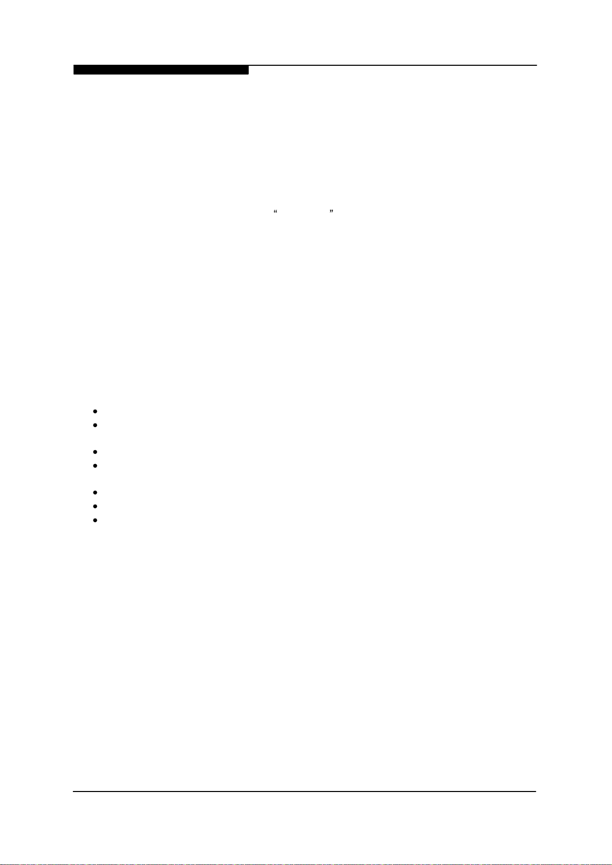
The Keston solar collector is made to an advanced specification. The collector is ultrasonic
welded and made with a vacuum deposited titanium selective surface. For pitched roof
installations, the collector comes with a roof mounting frame which consists of:
4 mounting plates (6 mounting plates for 3
collector systems)
2 roof S -brackets with top mounting bar and fixing nuts and bolts (3 roof S
-brack
ets for 3 collector systems)
4 L
-brackets for each collector
-
Installation & Servicing Instructions
Page :
4
Page 7
WD
435
/0/2006
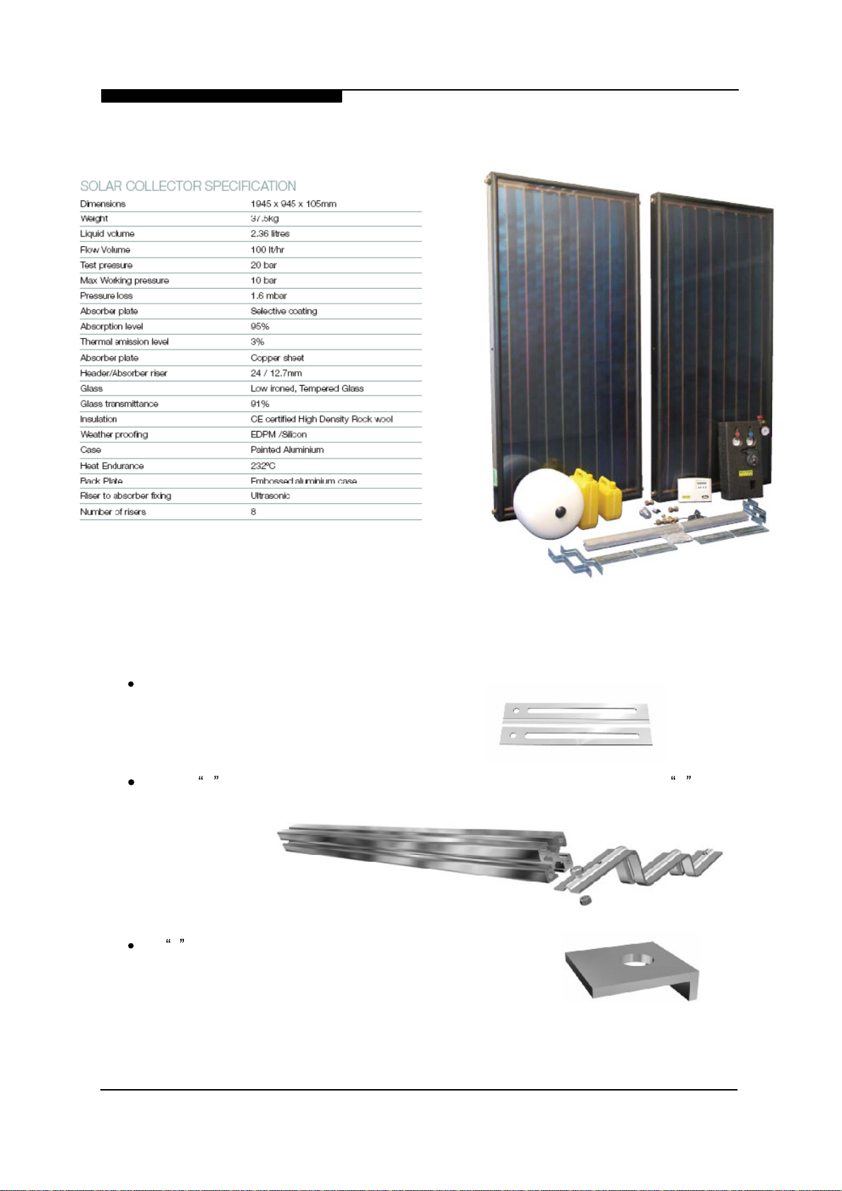
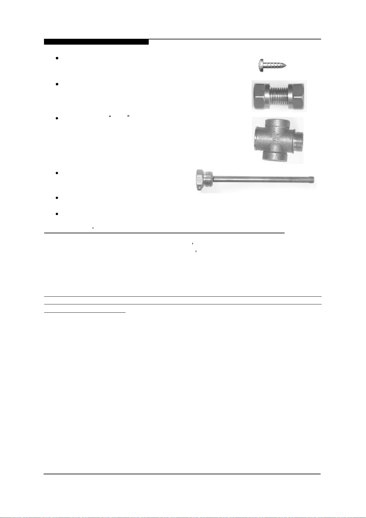
16 coach screws (24 coach screws for 3 collector systems)
2 Collector Inter-connectors (4 collector inter-connectors for
3 collector systems)
Collector flow cross fitting with integral sensor pocket and
top outlet (used for connection of the solar AA
tion valve, if roof mounted)
Temperature sensor dry pocket
Chapter 2 :
Installation
V and isola
-
Keston
Solar
Thermal
8 nuts, bolts and spring washers
4 aluminium strips (6 aluminium strips for 3 collector systems)
It is the installers responsibility to make sure the roof is water tight and secure.
Solar Thermal System is designed for operation in standard UK geographic applications. For
high wind exposure applications, it is the installer s responsibility to make sure the collectors
are suitably fixed to the roof. It is also the installer s responsibility to maintain the necessary
Health and Safety standards. Keston recommend the use of either scaffolding and/or custom
made solar installation access equipment for the safe lifting and installation of the solar
collectors. If in doubt, please use a competent roofer to install the collectors
The National Federation of Roofing Contractors (NFRC) offers a solar panel roof mounting
service via its network of approved members. The NFRC can be contacted on 020 7436
0387 or via www.nfrc.co.uk
The mounting plate and roof bracket are designed for use with concrete flat or profiled
pantiles. For rosemary clay tiles or slate, the top and bottom mounting bar can be fixed with
the 4 aluminium strips. Slates can be drilled with tile drills and rosemary tiles with a diamond
drill. Any holes in the roof (which ideally should be completely avoided) should be sealed
with an external grade low modulus silicon sealant or proprietary O rings. The aluminium
strips can be bent to the shape of the tile to suit any profile. The aluminium strips must be
coach screwed to either the rafters or noggins firmly located between the rafters. For
rosemary tiles, Keston suggests using two coach screws to fix one end of the aluminium
strip to the rafter and the feeding the strip out between two tiles and screwing the mounting
bar to the exposed end of the strip.
The Keston
.
Installation & Servicing Instructions
Page :
5
Page 8
WD
435
/0/2006
Profile of Aluminium
Strip
Chapter 2 :
Installation
Suggested side profile
shape of aluminium
strip for a rosemary tile
roof
Keston
Solar
Thermal
Mounting
Bar
Location of
coach screws
Another method for Rosemary tiles is to use the roof S -brackets as provided and then
weathering the roof S -brackets into the roof with code 4 lead.
For slates, the tiles will need to be
drilled. The internal rafters can be
located by feeding an aluminium strip
out from the loft between the felt
sarking layers and then abutting the
aluminium strip against the roofing
rafter. The external exposed end of the
aluminium will indicate the location of
the internal rafter. Alternatively, use
noggins between the rafters to firmly
locate the aluminium strips.
Installation & Servicing Instructions
Sugges
ted
side profile
aluminium strip
Location of
Coach Screws
Profile of
Aluminium Strip
shape of
for a slate roof
Location of
Coach Screws
Mounting Bar
Felt Sarking
Slate Roof
Wooden Battens
Page :
6
Page 9

WD
435
/0/2006
Chapter 2 :
Installation
Keston
Solar
Thermal
For flat or mildly profiled concrete pantiles, the roof hooks should be mounted as follows:
If the pantile is profiled, there might be a need to locate the roof hook to the joist using the
mounting plate as a connector. Here is an example:
This example is based on a roof
with a timber sarking. If no
timber sarking is available, the
nuts, bolts and spring washers
as provided can be used to bolt
the roof hook to the mounting
plate. Another alternative is to
place a noggin between the
rafters to strengthen the mounting structure and screw the roof
hook to the noggin.
Once the 4 roof S -brackets (or
6 roof S -brackets for 3 collectors) are firmly located and in
position, the tiles which were
Rafters
Max 185cm
Installation & Servicing Instructions
Page :
7
Page 10

WD
435
/0/2006
Chapter 2 :
Installation
Keston
Solar
Thermal
removed to locate the hooks can be replaced. The top and bottom mounting bars can then
be bolted to the roof hooks.
The first collector slides into the bottom
bracket and is located on either side by
the L-brackets:
Bottom Fixing of the Collector:
Top Fixing of the Collector
Three dimensional diagram of final location of top of the collector:
:
Installation & Servicing Instructions
Page :
8
Page 11

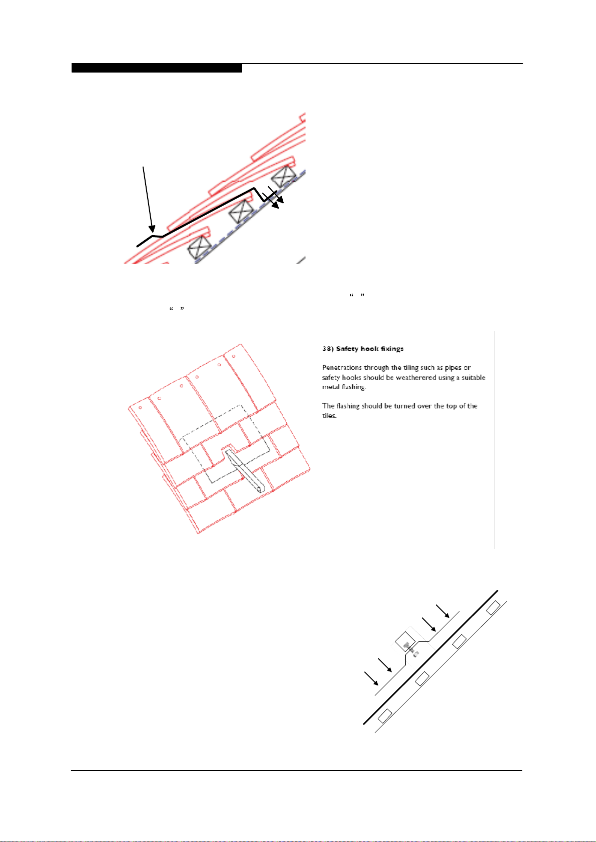
WD
penetration
penetration
AAV
Connectors
Connector
Connector
435
/0/2006
Chapter 2 :
The second collector is then
joined to the first collector using
the supplied Collector
Connectors:
The flow and return pipework can
be passed through the roof either
with a proprietary roof penetration tile or a Code 4 lead custom
made roof penetration tiles.
Ventilation tiles can sometimes
be adapted for this purpose.
Alternatively a silicon dektite
can be used or Keston also
supply as an optional extra a
lead pipe flashing tile which can
be adapted to suit most roof tiles.
Any exposed elements of the
roof penetration must be
carefully sealed with exterior
grade low modulus silicone.
Installation
Keston
Solar
Thermal
Roof penetration using a lead pipe flashing tile
Flow roof
Flow
Collector
Collector
Collector
The collectors should be
hydraulically piped as follows:
Return roof
Return
The AAV must be installed internally at a level above that of the panels (i.e. within the pitch
of the roof) to allow access for manual venting from within the roof space. The final part of
the roof installation is the insertion of the silicon PT1000 Collector Sensor into its mounting
pocket in the Flow Connector and feeding of the cable through or under the flow roof
penetration and through the felt or timber sarking so that the sensor cable is visible in the loft
space.
Installation & Servicing Instructions
Page :
9
Page 12

WD
435
2.
/0/2006
2
Installation of the Pump Station and other internal
Chapter 2 :
Installation
Keston
Solar
Thermal
components
The Keston Solar System features a flow and return line solar pump station and a solar
grade expansion vessel. This expansion vessel is 24 litres because it needs to absorb the
expansion of the steam in the collector during stagnation . All the components in the pump
station are solar grade.
The pump station has 28 mm flow and return fittings.
The pump is on the return line. The pump station contains a flowmeter, 2 check valves (to
stop the heat thermosyphoning out of the cylinder during the night), a pump, a flow and
return line thermometer, a manometer, two drain/fill valves, an SRV and a connection point
for the expansion vessel.
Mount the pump station on a suitable wall and connect:
top of the return line to the bottom of the collectors
top of the flow line to the top of the collectors
bottom of the return line to the bottom connection on the solar coil of the cylinder
bottom of the flow line to the top connection of the solar coil of the cylinder
a suitable drain valve in the return line
the manually isolated AAV in the flow line either internally or externally as close as
possible to the collectors
This can be seen in the Hydraulic and Control Circuit Layout in chapter 1. Externally terminate the Safety Relief Valve (SRV) where the exhaust can not scald anyone. If necessary,
this SRV can be removed and blanked off from the pump station and fitted in the return line
loft space to assist the external termination of the exhaust. The pipework from this valve to
the external location must be in copper, stainless or other suitable pipe and it is the
installer s responsibility to take into account the steam or extremely hot water that might
exhaust from this SRV.
These need to be reduced to 15 mm.
The expansion vessel should be fitted vertically at the end of at least 1m of 22 mm pipework.
This pipe length is to provide a water buffer to protect the vessel from extreme
temperatures generated during stagnation conditions. If 1m of pipe cannot be
accommodated a small buffer vessel may be considered. The expansion vessel must be
mounted with the water side of the diaphragm above the air side.
2.
3
Electrical installation and Solar Unvented Cylinders
The Keston Solar System is supplied with a Differential Temperature Controller (DTC) and 2
silicone high temperature PT1000 temperature sensors. The Keston DTC has several
functions which improve performance and efficiency and also record historical data which is
useful for diagnostic analysis of the system performance. All electrical installation must take
into account part P of the wiring regs and pipes, pump, cylinder etc. must be bonded in
accordance to BS 7671.
Installation & Servicing Instructions
Page :
10
Page 13

WD
435
/0/2006
Chapter 2 :
Installation
Keston
Solar
Thermal
Power for the DTC can be taken from either the 10 way central wiring centre if used (the
solar controller is part of the heating control circuit and so this is the ideal location) or alternatively from a 230 V 3A fused spur.
The DTC is designed
for use with solar
thermal water heating
systems only
The Keston DTC is permanently on and functions by measuring the temperature in the
collector (T1) and the temperature in the solar section of a twin coil cylinder (T2). When the
difference between collector and cylinder temperatures (T1 T2) reaches 8 degrees (adjustable), the DTC switches the solar pump (R1) on. When the difference between collector and
cylinder temperatures (T1 T2), reaches 4 degrees (adjustable), the DTC switches the solar
pump (R1) off again.
The Keston DTC also has modulating speed control of the pump, storage temperature limita
tion and full monitoring of the hours of operation and maximum and minimum temperatures
at T1 and T2. It is strongly recommended that the collector temperature limit, solid fuel/flue
tank regulation and antifreeze functions are left switched off.
Installation
Choose a suitable location where the building occupants can easily access the control
buttons and display of the DTC and fix screw 1 to the wall. Hang the controller onto this
screw and use the DTC as a template to position screws 2 and 3.
Electrical Socket connections on the DTC
Electrical Connections. To avoid potential interference, the low voltage cables connecting
sensors T1 and T2 to the DTC should be run at least 10 cm distant from any power cables.
-
Sensor T1 should be located in the flow panel connector and terminated in the loft.
Installation & Servicing Instructions
Page :
11
Page 14

WD
435
/0/2006
Chapter 2 :
Installation
Keston
Solar
Thermal
Both sensors T1 and T2 have no polarity. If the cable length between the DTC and T1 is less
than 75m connect T1 to the DTC with 0.75 mm2 dia two core cable. If the cable length
between T1 and the DTC is between 75 and 150 metres, use 1.5 mm2 dia two core cable.
The cable length between T1 and the DTC must be no more than 150m.
Position the ends of the T1
cable in sockets 7 and 8 on the
DTC. Connect sensor T2 in
sockets 9 and 10 and the
sensor end in the solar section
sensor pocket location in the
twin coil cylinder. This should
be either close above or in the
middle of the solar coil. If
sensor T2 needs extending,
please follow the same cable
diameters requirements as for
T1.
Connect the 230 V 3A fused
live to socket 4, the associated neutral to socket 3 and earth to socket 1 or 2. Using appropriate heat resistant flex, wire the solar pump in the pump station to socket 6 for live, socket
5 for neutral and either sockets 1 or 2 for earth. Replace the electrical connection cover.
The above diagram shows the four control buttons and LCD display on the DTC. The DTC
has 2 main menu options,
When in
READINGS
READINGS
and
ADJUSTMENTS
.
, after pressing the OK button, you can scroll up and down through
the readings using the up and down scroll buttons. At any time whilst scrolling through the
readings, you can return to the main menu by pressing the Menu button. The available
readings are:
stor. Tank:
Collector:
col.
Max:
col. Min:
st. tank max:
st. tank min:
d-R1 hrs:
x-R1 hrs:
Installation & Servicing Instructions
°C
°C
°C
°C
°C
°C
T2 - temperature in solar section of cylinder
T1 - collector temperature
Maximum collector temperature recorded
Minimum collector temperature recorded
Maximum cylinder temperature recorded
Minimum cylinder temperature recorded
hours Hours
hours
Total hours of solar pump operation since installation of DTC
of solar pump operation since last reset
Page :
12
Page 15

WD
435
/0/2006
All the maximum, minimum and hours readings (except for total pump hours) can be reset by
holding the OK button down for 2 seconds when this reading is visible in the display. These
maximum, minimum and hours readings can be used for diagnostic analysis of the performance of the solar system.
Chapter 2 :
Installation
Keston
Solar
Thermal
Whilst in the main menu, you can scroll between READINGS
using the scroll buttons. Whilst in ADJUSTMENTS , you can enter the submenus
PARAMETERS , FUNCTIONS
Menu at the same time. You can scroll through these 3 submenus using the up and down
scroll buttons.
Whilst in any of the 3 submenus, you can enter the settings by pressing the OK button.
Then, whilst below the submenus, the scroll buttons move you between the various settings.
PARAMETERS
st. Limit:
ON-TDiff:
OFF-TDiff:
The
st. limit: 60 °C
or conditioned water area when the temperature can be reset up to 80 °C. Consideration of
point of use scalding should be considered when altering the store limit temperature.
use of Thermostatic Mixing Valves (TMV) is important for raised store temperatures.
ON-TDiff: 8 K
long pipe run when the two values can be increased in proportion to the temperature drop on
the flow line between the collector and store.
contains the following three settings (with the recommended values):
60 °C
M
8 deg
4 deg
should be left at 60 °C unless the solar system is installed in a soft water
should be left on 8 and
and
MAN. OPERATION by pressing the buttons OK +
aximum store temperature at sensor T2
T1-T2 to bring pump on - default setting 8 deg
T1-T2 to turn pump off
OFF-TDiff: 4 K
- default setting 4 deg
should be left on 4 unless there is a
and ADJUSTMENTS
The
FUNCTIONS
Tmin a. Fuel:
col. Limit:
Antifreeze:
speed contr:
T1: KTY
MAN. OPERATION
pump P1:
preset config.
To change any of the settings whilst in the submenus, the OK button should be held down
for 2 seconds.
All the functions should be left as factory preset. The speed control function will be further
discussed in the commissioning section. The manual control of the pump is useful during
commissioning of the solar system.
Installation & Servicing Instructions
contains the following settings (with the recommended values):
OFF
OFF
OFF
ON (modulating pump speed control. See commissioning)
OFF
contains the following settings (with the recommended values):
OFF
(ON makes the DTC a solid fuel controller)
(collector cooling function not required by Keston solar)
(runs system without antifreeze. For hot climates)
(using system with alternative sensor types
(manual control of the solar pump)
(returns controller to factory preset conditions)
)
Page :
13
Page 16

WD
435
/0/2006
Chapter 2 :
Installation
Resistance values of the temperature sensors
Technical data
Keston
Solar
Thermal
Installation & Servicing Instructions
Page :
14
Page 17

WD
DHW Output
435
/0/2006
Chapter 2 :
Installation
Keston
Solar
Thermal
Unvented cylinders and the Keston Solar System
The second level of control on an unvented G3 cylinder requires that there should be an
isolating valve within one metre on the flow line of the boiler coil to cylinder connection. This
isolating valve is wired to a manual reset thermostat. This boiler system solution is not feasible for a solar system as, due to the raised temperatures and pressures, even solar grade
valves installed on the flow line can fail.
Therefore, ideally the power to the 10 way central heating control box is wired through a
single manual reset thermostat located in the top of the unvented cylinder. This will cut
power to both the boiler and solar circuits.
Proposed Manual Reset and Cylinder Thermostat Electrical Wiring Diagram
L from Fuse board
N from Fuse board
N to 10 way box
L to 10 way box
From Timeclock
N
from
10 way box
E
L from
10 way box
To Boiler
Manual Reset Stat
Cylinder Stat
Dual
Aquastat
Boiler Coil
Motorised Valve
Brown
Blue
Green/Yellow
Grey
Orange
Brown
230 V supply to DTC
(from 10 way box)
E
N from 10 way box
L from 10 way box
Socket 1 or 2
Socket 3
Socket 4
Alternatively, two manual reset thermostats can be employed on the heating system. One
thermostat, located to respond to the boiler coil, is wired conventionally as per manufacturer s instructions to the boiler heating controls and the solar manual reset thermostat,
Installation & Servicing Instructions
Page :
15
Page 18

WD
435
/0/2006
Chapter 2 :
Installation
Keston
Solar
Thermal
located to respond to the solar coil, is wired to isolate power to either the DTC or the solar
pump.
Please also note that if the panel is located below the cylinder, there is potential for the heat
to thermosyphon from the collector to the cylinder and in this case, the only solution is to fit a
solar grade isolating valve within one metre of the solar return line to cylinder connection
and this valve must close as soon as the manual reset thermostat is opened.
Part L Building Regulations
The installer has a requirement under Part L to confirm installation or install a cylinder
thermostat and zone valve to control the boiler section of the cylinder hot water temperature
and to provide a boiler interlock. The cylinder insulation must also be brought up to Part L
standards.
Installation & Servicing Instructions
Page :
16
Page 19

WD
435
/0/2006
3
.
Commissioning of the Solar System
An important safety consideration on filling the solar system is to prevent the fluid boiling on
entry into the collector. If there is any chance that the collector will exceed 100 °C during the
commissioning procedure, the collector must be covered.
By turning both of the thermometers on the pump station an eighth of a turn clockwise, the
check valves are disconnected from the solar primary circuit and fluid can flow in either
direction. By turning both the thermometers a quarter turn clockwise, the check valves are
fully closed.
Chapter 3 :
Commissioning
Keston
Solar
Thermal
1)
2)
3)
4)
5)
6)
7)
8)
9)
10)
11)
12)
13)
14)
Open the circuit by disconnecting both check valves (thermometers an
clockwise).
Fill the solar primary circuit and flush the circuit of all the installation debris.
Mix the Keston supplied antifreeze with water at a ratio of 1 part antifreeze to 3 parts
water (25% concentration). In climates where 20 °C can be realised, increase this
concentration ratio to 40%. We suggest that due to the low volume in the solar primary
circuit, that the solar system is filled from a dosing station as supplied by the water treatment
specialists. Keston strongly recommend that a filling loop is not fitted on the solar primary
circuit as this can lead to dilution of the antifreeze.
Check the expansion vessel has a pre-commissioning pressure of 1 bar.
Connect the dosing vessel to the lower filling valve, make sure that the check valves
are in the open position and that the manual isolator on the
Fill the circuit from the dosing vessel and pressurise the circuit to 1.5 bar.
Manually switch the
Purge the remaining air from the circuit and isolate the
Activate the check valves by turning the thermometers an eighth of a turn anticlockwise.
Whilst the
that the
litres/min for 2 collectors and 6.3 & 9.45 litres/min for 3 collectors.
viewed as the bottom line on the
Ideally, the pump is set on speed 1 and the
position.
After purging the air, manually switch the
hydrometer, recheck the concentration of the fluid in the circuit. Adjust to correct
ratio.
Reset the
the
flowrate
by improving the heat recovery from the solar collectors and reducing pumping electrical
losses. Alternatively, if the
litre/min/m2 collector.
The
Leave it on this setting unless soft water is available in the property. If soft water is
available, the thermostatic cylinder limit can be reset up to 80 °C.
Always, even at 60 °C, thermostatic mixing of the water should be considered. Water
can scald from 47 °C. Any
points-of-use should set the temperature above 55 °C and below 60 °C.
DTC
flowrate
DTC
to suit the differential temperature. PSC is employed to improve system efficiency
DTC
thermostatic cylinder limit temperature (
DTC
to on and check pump is running.
is on manual, set the pump on setting 1 and adjust the
is between 1 and 1.5
flowmeter.
to Auto. The Pump Speed Control (PSC) function will automatically adjust
PRC
function is switched off, make sure the
TMVs
litres/minute/m2 collector i.e. between 4.2 & 6.3
If necessary, increase the pump speed settings.
flowmeter
DTC
fitted close to the cylinder with long pipe runs to the
adjustment screw is in the vertical
to off and using a
st.
AAV
is open.
AAV.
The
refractometer
flowrate
limit) has a default of 60 °C.
eigth
flowmeter
flowrate
is set to 1
turn
so
can be
or a
Installation & Servicing Instructions
Page :
17
Page 20

WD
435
/0/2006
Chapter 3 :
Commissioning
Keston
Solar
Thermal
Commissioning Certificate
It is highly recommended that a form of commissioning certificate is left with the
householder for safekeeping. The certificate should contact the following information:
Expansion vessel pre-charge pressure
Solar primary circuit pressure
delta T
delta
st.
TMV
T
Limit
fitted
on
off
If yes, point-of-use temperature
PSC control
If no,
flowrate
set to:
Antifreeze concentration
Antifreeze supplier
bar
bar
K
K
°C
Yes/No
°C
Yes/No
litres/min
%
Keston / Other
Installation & Servicing Instructions
Page :
18
Page 21

WD
435
/0/2006
Chapter 4 :
Handing Over To The User
Keston
Solar
Thermal
4.
Handing over to the user
There is no day-to-day control required of the Keston Solar System. The system is
completely self-sufficient and requires no maintenance on the part of the building occupants.
However, most customers like to be informed about the solar system and how to maximise
the performance of the solar system so that they use as little fossil fuel for hot water heating
as possible.
Therefore, the customer should be shown:
On the
DTC,
the READINGS menu and how to scroll through the readings.
Some explanation of maximum and minimum readings and hours of operation is
recommended.
So that the user can check system operation during solar radiation, the functioning
of the
If an
flowmeter
unvented
and the on symbol on the LCD display of the
DTC
cylinder is fitted (such as the Keston Spa), the manual reset
thermostat and action to take if this thermostat needs to be reset i.e. a solar
competent heating engineer should be called out to check the source of the fault.
The exhaust point of the
SRV
and what action to take if steam or water is seen
coming from the end of this pipe i.e. a solar competent heating engineer should be
called out to check the source of the fault
How to manage the boiler cylinder thermostat and
timeclock
so as to maximise the
solar gain. Please see below.
The installation manual and commissioning certificate, both of which should be left
on-site
Maximising the output from the Keston Solar System
If the solar system has been connected to a twin-coil cylinder, both the boiler heating circuit
and solar heating circuit can heat this cylinder. The lower section of the cylinder is available
for the solar circuit. The upper section of the cylinder is available to the boiler circuit.
The solar heating circuit operates most effectively when it has the largest volume of water to
heat. Therefore, especially during the summer months, Keston strongly recommends that
the boiler control circuit is left off during the solar day (when the sun is likely to heat the
cylinder) so as to provide the solar circuit with as much work as possible. This will minimise
the fossil fuel heating bill. The cylinder is well insulated and so will retain its heat for a long
time unless the water is run off at the points-of-use.
The building occupant s lifestyle will determine the optimum settings for the boiler controls.
The aim is to leave a reasonable volume of water in the boiler section of the cylinder at a
temperature which is warm enough to still provide an adequate temperature at the points-ofuse and cool enough to obtain as much of the available solar energy as possible. Many
occupants find that they can often run on solar only during the summer months. However,
the occupants should be warned about the
legionella
risk of running on a solar only setting
i.e. the boiler section of the cylinder should reach at least 55 °C everyday and preferably 60
°C everyday.
Installation & Servicing Instructions
Page :
19
Page 22

WD
435
/0/2006
Chapter 4 :
Handing Over To The User
Keston
Solar
Thermal
If the customer s find that they have enough water available for washing etc. during the
morning and early afternoon period, one ideal setting is to switch the boiler section of the
cylinder on everyday for an hour between 8 and 9
pm.
This setting will make sure the cylinder passes through the 55 to 60 °C once a day and also provide the solar circuit with the
maximum workload during the solar day.
Ultimately the customer should find their own optimum boiler timings for
their needs. The less the boiler is fired for
DHW,
the better.
DHW
according to
Installation & Servicing Instructions
Page :
20
Page 23

WD
435
/0/200
6
Chapter 5 :
Servicing
Keston
Solar
Thermal
5.
Routine Servicing
MAINTENANCE SCHEDULE TO BS 5918: 1989 -
Code of practice for SOLAR HEATING SYSTEMS FOR DOMESTIC HOT WATER
British Standards Institution (Indirect)
While a properly designed and installed solar heating system should be expected to give a
service life comparable to that of other types of heating systems, some maintenance may be
necessary to maintain the efficiency of the installation.
During a maintenance inspection the following items should be checked:
1. That unions and glands are free from weeps
2.
3.
4.
5.
6.
7.
That the glazing seals are
weathertight
and sound
That the collector circuit is free from air
That all air eliminators, non-return valves, solenoid valves and motorised valves are
operating correctly
That the correct volumes and system pressure are maintained (at rest and in
operation)
That the electrical controls are operating correctly to the manufacturer's instructions
That circulating pump is operating without undue noise or vibration
8.
9.
10.
That all insulation is firmly attached
That all covers are in place
That no condensation or damp spots are apparent, particularly around the pipes and
fixings in the roof
11.
12.
13.
14.
15.
16.
17.
18.
That the roof fixings are firm and the roof covering is free from cracks
That the weathering is properly protecting the structure
That the collector glazing is clean
That the glazing is free from cracks
That there is no evidence of serious corrosion
That any
paintwork
is sound
That all sensing devices are firmly and properly in place
That the life of the heat transfer fluid has not expired
Keston recommend that the above maintenance procedure is followed annually, preferably
when the boiler and/or cylinder is also serviced.
The antifreeze has a service life of 5 years and so this fluid must be changed at each 5 year
interval.
Before decommissioning/draining the solar circuit, make sure there is no chance for collector
temperature to exceed 100 °C, that all check and isolating valves are open and that the
antifreeze mixture is captured in storage vessels for safe disposal at a recognised safe
disposal centre.
Installation & Servicing Instructions
Page :
21
Page 24

WD
435
/0/2006
Chapter 6 :
Fault Finding
Keston
Solar
Thermal
6.
6.1
Fault Finding
No flow solar primary circuit
POSSIBLE CAUSES
System in stagnation
Airlock in circuit
Manometer on low
pressure
Faulty check valve
Steam escaped from
Fluid exhaust from
SRV
Faulty or blocked pump
Frost damage to collector
Blocked circuit
PT1000
Faulty
6.2
sensors loose
DTC
Low performance of solar system
POSSIBLE CAUSES
faulty
DTC/system
settings
AAV
ACTION
Check
st. limit
at
max
Purge air
Refill and manually operate
DTC
Check open and if necessary, replace
Manual isolate
Check expansion vessel,
AAV
and refill. Check expansion
SRV
& refill
vessel
Free, clean and if necessary, replace
Replace collector and
recommission
circuit
Check for degraded old antifreeze blockage or limescale
blockage
Relocate sensors
See below
ACTION
Check delta Ton and delta
Speed Control. Also check functions ON/OFF and
T
settings,
off
flowrate
and
Pump
DTC
Auto
on
F
aulty
PT1000
sensors
Faulty pump
R
estriction in circuit
I
nadequate air removal
L
oss insulation
Boiler primary circuit
providing too much heat
6.3
Water too hot at points-of-use
POSSIBLE CAUSES
Incorrectly set
Incorrectly set
F
aulty boiler primary circuit
6.4
Faulty
DTC
TMV
DTC
POSSIBLE CAUSES
No LCD display
LCD says Short circuit
LCD says
Interruption T1/T2
Check sensor location and check electrical resistance to
temperature (see table in ch 4)
Check pump is rotating. Check valves open and pump
speed correctly set
Check circuit components and for old antifreeze/limes
restriction in pipes
Purge air
R
eattach insulation
R
eset central heating
timeclock
to give solar system more
cylinder water to heat
ACTION
Check
Check output temperature from
st. limit
on
DTC
TMV
Check out boiler primary circuit for faults
ACTION
No power supply, check fuse and 230 V
T1/T2
Check relevant sensor for short circuit
Check relevant sensor for circuit break
cale
Installation & Servicing Instructions
Page :
22
Page 25

WD
435
/0/200
6
Chapter 7 :
Parts List
Keston
Solar
Thermal
7.
Parts List
Keston Boilers Solar Kits contain the following items:
Description
Solar Collector Panel
CLS1808
Onto roof mounting set
Flat Roof Stand
Collector Inter-connectors
Flow connector fitting
Panel Sensor Pocket
Part Number
SP18101000
SP18102000
SP18103000
SP18104000
SP18100040
SP18305000
SP18105010Automatic Air Vent
Isolating Valve
Solar Pump Station
Solar Controller
(DTC)
Expansion Vessel - 18
Expansion Vessel - 25
Vessel Fixing Bracket
Vessel Connecting Hose
litre
litre
SP18106000
SP18202000
SP18301000
SP18402000
SP18407000
SP18407000
SP18408010
Glycol Antifreeze
The above kits are also available with Keston
SpaTwin
200 (200 litre) is packaged with a 2 panel kit, a
SpaTwin
packaged with a 3 panel kit.
Kit
PA2
8
litre
double coil
Kit
PA3
10
litre
SpaTwin
Kit
FA2
Kit
3232
--32
32-2121
1111
1111
1111
1111
1111
1111
-1-1
1-11111
1111
8
litre
unvented
10
cylinders. A
300 (300 litre) is
FA3
litre
Keston supplied optional extras for roof penetration:
Keston can also supply kits for in-roof mounting of the panels. Contact Keston for more
detail.
Installation & Servicing Instructions
Page :
23
Page 26

KESTON SOLAR
THERMAL SYSTEMS
INSTALLATION KEY POINTS
AND
COMMISSIONING CHECKLIST
Installation Manual has been carefully read and followed.
The roof mounting of the collectors is secure from both wind damage and rain
penetration.
The fully-filled solar circuit has been installed to manage both freezing and stagnation conditions.
Has the
and commissioning?
Have both check valves (under temperature gauges) been left in the correct
position?
Does the
and has the flow rate been appropriately set with either PSC or 1
collector?
The solar-grade expansion vessel must also be on the return pipework
be mounted vertically at the end of a 1m length of 22 mm
collector.
installed with a pre-commissioning pressure of 1.0 bar?
Drain/fill valves have been selected to deal with temperatures and pressures
realised
Brass olive compression fittings have been used within 2
lead-free solder fittings on the rest of the solar primary circuit and all the
copper or stainless steel (or superior specification to the above).
High-temperature
solar primary circuit.
All external insulation, cable, cable clips
Thermostatic Mixing Valve
provided.
Diferrential
legionella
The differential controller has been correctly wired. That is an electrical supply of
230 V fused at 3A and the solar pump has been wired in heat resistant flex. Cables
between the sensors and the differential controller are in 0.75
75 m and 1.5
For
tial controller must be wired via a mechanical reset thermostat.
On an
solar-grade 2 way valve must be located in the return
store.
The pipes, pump and cylinder are bonded to BS 7671.
To confirm with Part L, the installation of a cylinder thermostat and zone valve to
control the boiler section of the cylinder hot water temperature and a boiler interlock
has been confirmed or provided. The cylinder has been suitably insulated.
A Commissioning Certificate is completed and the Certificate and solar system has
been fully handed over to the customer.
AAV
been fully isolated after setting the pressure to 1.5 bar, purging of air
SRV
terminate to a safe location, have the pump valves been left open
Expansion vessel is supplied.
in that part of the circuit.
armaflex
Control
protection implemented
unvented
unvented
cylinders, for the second level of control, either the pump or differen
(DTC)
mm2 for up to 150 m length and located away from 230V interference.
cylinder, if the collectors are vertically below the hot water store, a
or similar insulation has been used throughout the
(TMV)
settings are as directed in the manual and suitable
litre/min/m
pipework
Has the expansion vessel been correctly
metres
etc
are UV-resistant.
or similar protection for the building occupants is
pipework
for each m2 of
of the collector and
mm2 cable for up to
within 1 m of the
2
and should
pipework
is
-
WD436/0/2006
Page :1
 Loading...