

Page 1
COMBINATION WALL HUNG
GAS BOILER
MODEL RSM 20/FB
INSTALLATION & SERVICING
INSTRUCTIONS
DATA BADGE UNDER FRONT PANEL ON BURNER COVER
Manufactured by
THERMOMATIC SRL Casalecchio Di Reno Bologna Italy
exclusively for
High Efficiency Domestic & Commercial Boilers
34 West Common Road Hayes Bromley Kent BR2 7BX
Telephone : 020 8462 0262 Fax : 020 8462 4459
e-mail: info@keston.co.uk Web: www.keston.co.uk
Page 2

Page 2
Page 3
TECHNICAL DATA
Heal input (fixed) 26.2kW (89.400 Btu/h)
Heal output 23kW (78.500 Btu/h)
Burner pressure
Burner
14mbar(5.6in.w.g.)
Inlet 2Ombar
Worgas Thermomatic
3 injector 2.35 - 2.70 - 2.35 n
Gas control valve Honeywell VK 4105G
Control Box Honeywell VK 4105G
Filling loop
Inter Albion with Alhilil
double check valve
Boiler control thermostat Ranco K36 Y21
Bimetallic Priority thermostat Cewal 91931199
Overheat thermostat Ranco LM7 P5 043
Anticondensing Thermostat Imit TR2
Electrical supply 240V-50HZ
Power consumption 180 W
Internal fuse rating 3A
Weight empty 77 kg (169.7 Ib)
Weight full 92 kg (203.O Ib)
CH max pressure 3 bar (44 psi)
CH min working pressure 0.5 bar (7.4 psi)
DHW max pressure 10 bar (146 psi)
DHW min working pressure 0.6 bar (8.7 psi)
CH expansion vessel 8 litres charged to 0.5 bar (7.4 psi)
DHW expansion vessel
0.1 60 litres charged lo 3.5 L
(51.5 psi)
CH max temperature 90°C
Design temperature rise 11°C
DHW flow at 30'c rise 11.0 l/min
DHW flow at 35'c rise 9.21 l/min
Page 3
Page 4

43
Contents Figures
Section Page No. Page
Technical Data Inside Internal Design 1.1 5
Front Cover Control Panel 2.1 6
General Description 1 5 Connections 3.1 6
Operating Sequence 2 6 Alternative top tip system 3.1. A 7
Related Documents 3.1 6 Sealed system filling & make-up 3.1. B 8
Gas Supply 3.2 6 Pump Performance 3.2 9
Water Systems 3.3 7 Typical Heating System 3.3 7
Flue Systems 3.4 9 Domestic Hot Water Supply 3.4 9
Appliance Location 3.5 10 Standard Flue Kit Components 3.5 9
Electrical 3.6 11 Optional Horizontal Extension
Flue
Installation Procedures 4 13 Kit Components 3.6 9
Flue System: Cutting & Siting of Terminal 3.7 7
Assembly 4.7 13 Clearances 38 11
Connecting Services 4.8 18 Functional Flow Wiring Diagram 3.9 10
Filling Loop Assembly 4.9 18 Disassembly of panels 3.10 12
Commissioning 5 18 Wiring Diagram 3.11 38
Procedures for part
replacement
Draining 6.3 20
Replacing Fan 6.5 20 Appliance Mounting 4.1 13
Replacing Air Pressure Switch 6.6 21 Flue Positioning 4.2 13
Replacing DHW Expansion
Vessel
Flue Connection 4.4 14
Replacing Automatic Air Vent 6.8 21 Flue Connection 4.5 14
Replacing CM Expansion
Vessel
Replacing Bimetallic Priority Vertical Flue Terminal Locations 4.7 16
Thermostat 6.10 21 Assembled Extended Vertical
Replacing Solenoid of Gas Kit 4.9
Control Valve 6.11 21
Replacing Multifunctional Filling Loop Assembly 4.11 18
Gas Control Valve 6.12 22 Gas Control Valve 5.1 19
Replacing Circulating Pump 6.13 22 Central Heating Expansion
Replacing thermostatic
T/P Gauge 6.14 22 Thermostat Positions 6.4 22
Replacing Safety Valve 6.15 22 Pressure Relief Valve 6.5 22
Replacing Burner 6.16 23 6.7 23
Replacing Injectors 6.17 23 Top view of Boiler 8.1 32
Replacing Flame Sensing
Ignition Electrodes 6.18 23
Replacing Electronic Control
Box 6.19 23
Replacing Green Operating
Light & Red Lockout Button 6.20 23
Replacing On/Off Summer/
Winter Switches 6.21 23
Replacing Filling Loop 6.22 23
Fault Finding Algorithm 7.1-12 24 – 31
Routine Servicing and
Cleaning 8 32
Short Spare Parts List 34 – 36
Complete Boiler Wiring Schematic 37
Wiring Diagram 38 Manual Addendums 40 -
6 20 Time Clock Wiring 3.12 39
Honeywell T6360B Room Slat
Wiring 3.13 39
6.7 21 Flue Positioning 4.3 14
6.9 21 Vertical Flue Clearances 4.6 16
Flue
Vessel
Spare Parts
4.8 & 17
6.2 21
33, 34
Page 4
Page 5
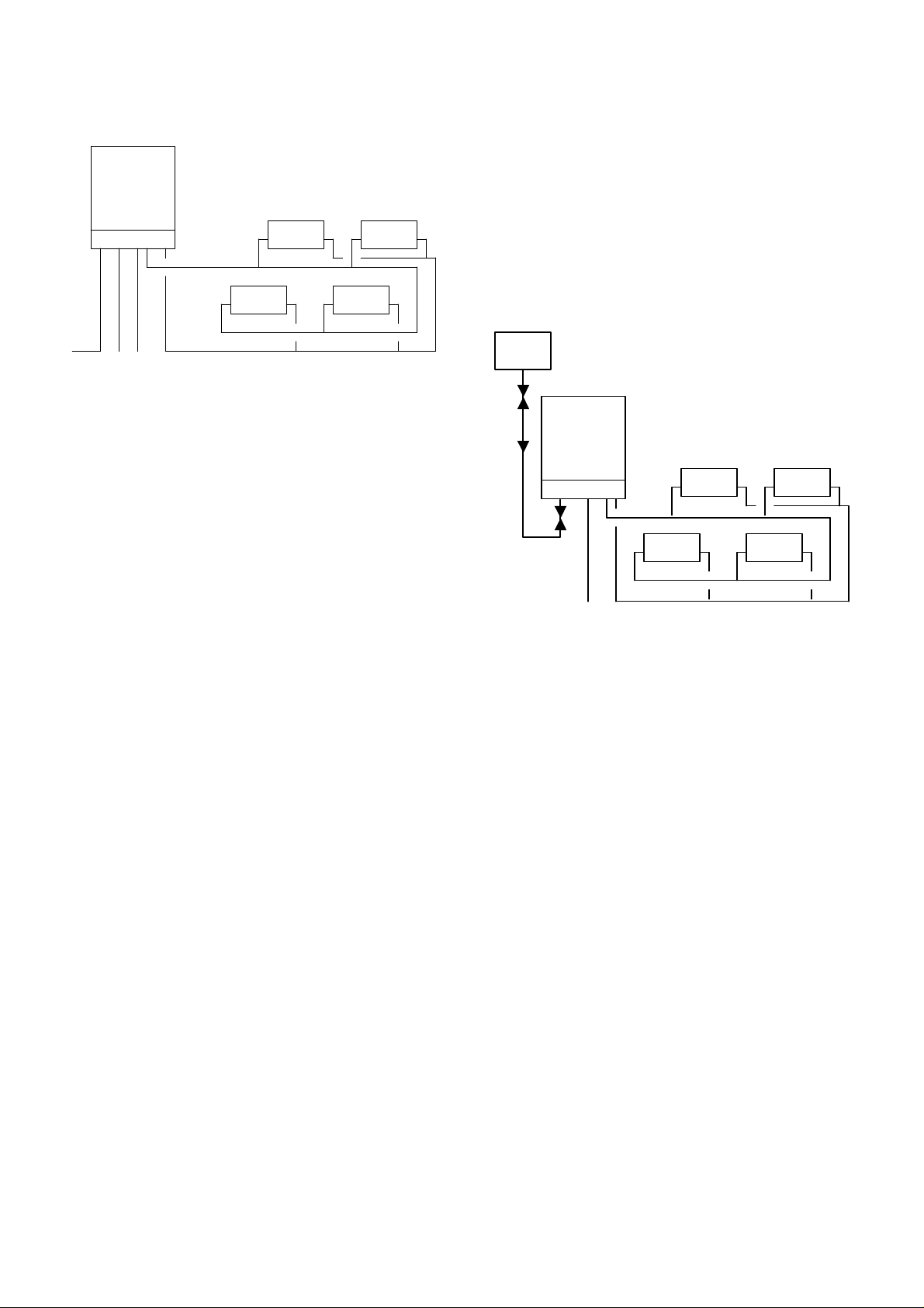
1 GENERAL DESCRIPTION (Fig.1.1)
The Thermomatic RSM 20/FB is a wall mounted
water jacketed vertical tube Combination Boiler fitted
with a copper coil to give an immediate supply of hot
water.
The appliance is room sealed and fitted with a coaxial
duct for fan powered ventilation, designed for exit to
either side or to the rear of the appliance.
The copper coil containing 2 litres of hot water is
indirectly heated, giving an immediate and continuous
hot water supply.
The central heating pump will not operate until
the boiler temperature reaches 60°C. The pump is
controlled by a capillary thermostat called the anticondensing thermostat. In addition, a bimetallic
priority thermostat will stop the pump as soon as
domestic hot water is drawn. This allows the full heat
output to be directed to supplying hot water only.
The appliance jacket extends to burner level, so the
walls of the combustion chamber are water-cooled.
This prevents the intense local heating usually
associated with combination boilers and considerably
prolongs the appliance life.
The domestic hot water, being indirectly healed
through a coil of a larger diameter than normally
used, is not so easily affected by calcium impurities
that build up lime scale. This together with the flexing
of the coil due to temperature changes, means
calcium "build-up" is considerably lessened.
With the Summer/Winter switch set to Winter the
appliance will automatically adjust to the central
heating output, which may be a single radiator, ot
any number within the heat ouput of the appliance.
The Thermomalic does not require a 'by-pass' and all
radiators can be fitted with thermostatic radiator
valves.
Unlike many other combination boilers, the Thermomalic will operate on low water pressures. The
boiler within the casing is cylinder shaped and fitted
with vertical copper flue tubes through which the gas
products pass. These tubes are fitted wiih stainless
steel baffles to increase efficiency and to rapidly
conduct the heat from the gas products to the water
contained within the cylindrical heat exchanger.
An extended copper coil fitted around the vertical
flue tubes is within the water content. The water
content connects to the central healing system and
indirectly heats the domestic water passing through
the coil.
A SIT Controls multifunctional control with electric
ignition is used and temperatures of both central
heating and hot water ate controlled by capillary
thermostats.
The flue extract fan incorporates a pressure control
switch which activates the gas control. In the case of
a fan failure of any kind the gas control fails to safely.
It is recommended that a scale inhibitor should
be fitted in hard water areas.
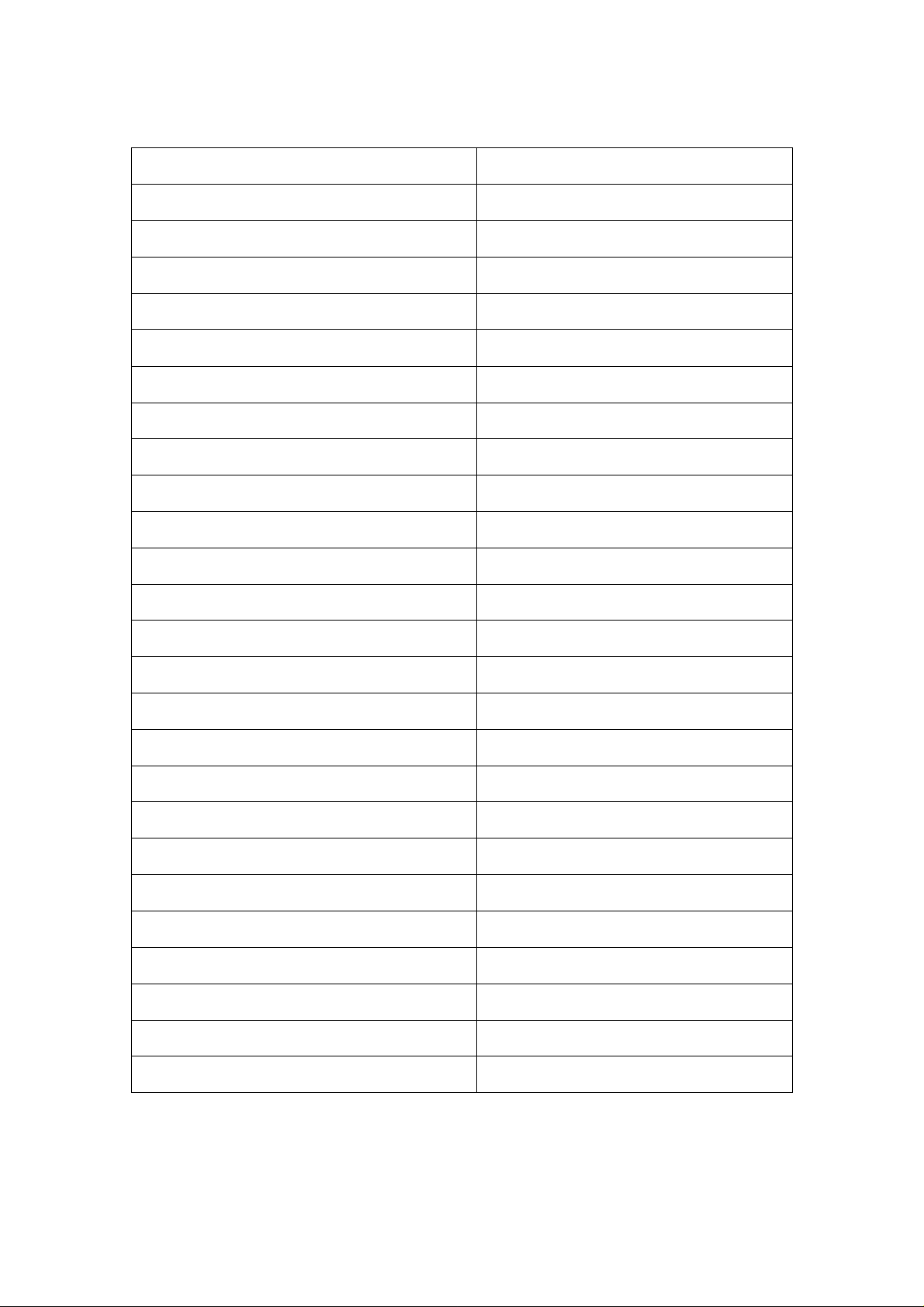
FIG.1.1 INTERNAL DESIGN
1 Manual air vent cock
2 Gas control valve
3 Stainless steel burners
4 Ignition electrode
5 Pocket for an anticondensing thermostat phial
6 Pocket For safety thermostat phial
7 Pocket for boiler healing thermostat phial
8 Water temperature gauge
9 Automatic air vent
10 Fan motor
11 Expansion vessel
12 Stainless steel Hue baffles
13 Boiler shell
14 Domestic hoi water copper coil
15 Circulating pump
16 Pressure relic! Safely valve
17 Water pressure gauge
18 Bimetallic priority thermostat
19 Air pressure microswitch
20 Air pressure switch body
21 Concentric flue/air pipe
22 Flue terminal
23 Flue hood
24 Electronic control box
25 Room sealed combustion chamber
26 Flame detection probe
27 Mini expansion vessel (Domestic)
Page 5
Page 6
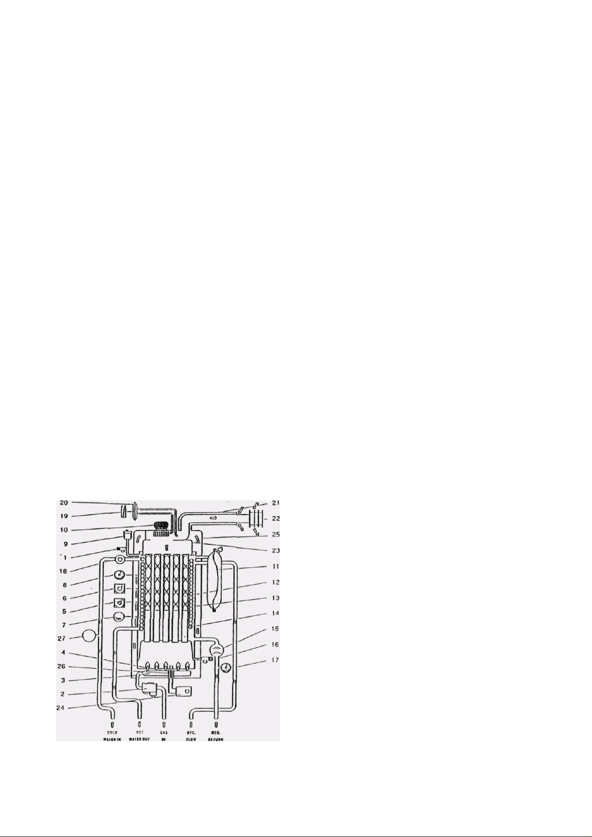
2 OPERATING SEQUENCE (Fig.2.1}
Red Light Central Heating Switch Temp. Press. Guage
Boiler Control Green Light Fuse On/Off Switch Overheat Switch
2.1 ON-OFF MAIN SWITCH
Allows the appliance to be manually switched on and
off.
2.2 CENTRAL HEATING SWITCH (SUMMERWINTER)
Allows the central heating and domestic hot water
supply to be switched on. or domestic hot water only
to be switched on.
2.3 BOILER CONTROL THERMOSTAT
Controls the temperature of the water fed to the
central healing system. The temperature can be manually adjusted between approximately 50" - 90*C ±
2°C.
2.4 OVERHEAT SWITCH
A boiler overheat switch will operate if the boiler
thermostat exceeds 90*C ± 3%. After determining the
season (of the boiler overheat thermostat operating,
the thermostat can be manually re-set. Note: thermostat control cannot be re-set until boiler temperature
falls below 80"C.
2.5 PRESSURE AND TEMPERATURE GAUGE
A combined boiler pressure and temperature gauge
indicates the pressure and temperature of the water in
the boiler. As a guide the pressure of water in the
boiler, with a pressurised system, can be set at 1 bar
when the water is cold.
2.6 BIMETALLIC PRIORITY THERMOSTAT
A bimetallic priority thermostat is fitted al the connection of the domestic cold water inlet to the boiler.
When a hot lap is opened, the bimetallic priority
thermostat is operated by the flow of cold water into
the boiler.
If the central heating switch (summer/winter switch)
is in the Winter position (i.e. central heating ON) the
bimetallic priority thermostat turns off the central
healing circulating pump.
When the domestic hoi water demand is satisfied the
bimetallic priority thermostat allows the pump to
restart.
When only a small domestic hot water flow is drawn
the bimetallic priority thermostat does not intervene.
2.7 ANTICONDENSING THERMOSTAT
This thermostat prevents the central heating emulating pump from operating until the boiler water
temperature reaches 60"C
3 GENERAL REQUIREMENTS
3.1
RELATED DOCUMENTS
It is the law that gas appliances be fitted by a
competent person. Failure to do so could lead to
prosecution. It is in your own interest, and that of
safety, to ensure compliance with the law.
Installation shall be in accordance with the following
documents:
- Gas Safety (Installation and Use) Regulation 1984
- Building Regulations
- Building Standards (Scotland) Consolidation
- Current IEE Wiring Regulations
- By-Laws of the Local Water Authority
- BS.6798: Boilers of rated input not exceeding 60KW
- BS5449: Forced circulation hot water systems
- BS.5546: Gas hot water supplies
- BS.5440: Part 1: Flues
- BS.5440: Part 2: Ventilation
- BS.6891: Gas supply
-
Where the appliance is installed in a timber framed
building, reference should be made to the British Gas
Publication reference DM2.
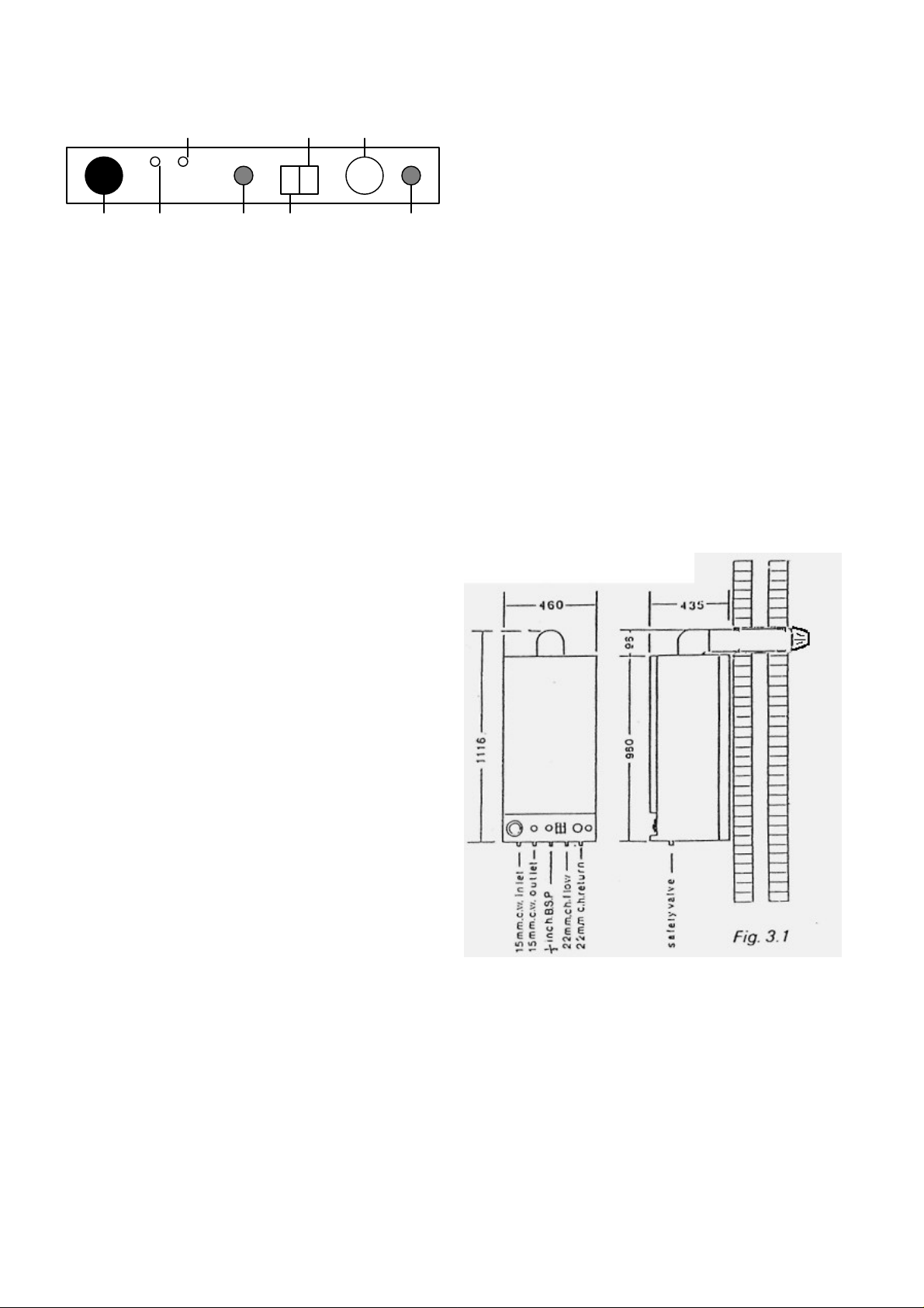
3.2 GAS SUPPLY
See fig.3.1 for connection
Fig. 3.1
A gas meter can only be connected by local gas
legions or by a local gas region contractor. An existing
meter should be checked, preferably by the gas
region, to ensure the meter is adequate to deal with
the rate of gas supply.
Installation of pipes should be in accordance with
BS.6891.
Pipework from the meter to the appliance must be of
adequate size.
Do not use pipes of a smaller size than the appliance
gas inlet connection.
The complete installation must be tested for soundness and purged as described in the above code
Page 6
Page 7
3.3 WATER SYSTEMS
Fig. 3.3 TYPICAL HEATING SYSTEM
3.3.1 Central heating
See Fig.3. f for connections
WARNING: When radiator(s) are at a higher level than the
boiler. A NON-RETURN VALVE MUST BE FITTED lo the
central healing systems flow pipe.
A. Old systems.
These* are likely to contain sludge and debris which, if passed
into the appliance, may cause irreparable damage to the pump
and other components. It is. therefore, highly recommended
that the old system be thoroughly flushed using such as
Fernox cleaner - use in accordance with the manufacturer's
instructions.
B. New systems
Must always be flushed of debris.
C. Design of system
The primary system must be of the sealed type, the designed
temperature rise should be 1 PC.
The following sealed system components are included on the
appliance:
i. Double check valve, stop valve and filling loop,
ii. 8 lilre central heating expansion vessel,
iii. Circulating pump.
iv. CALEFFI relief (safety) valve.
v. D.H.W, Expansion Vessel
vi. Combined temperature and pressure gauge.
D. Expansion vessel/sizing of system
Guidance is provided in BS.7074. Part 1 and BS.5449. The
maximum permissible capacity of the system, including the
appliance, will depend upon the initial design pressure.
As an example, for an initial design pressure of 1 bar the
maximum permitted capacity, including the appliance, is 70
titles.
For calculation purposes:
Existing vessel capacity - 8 litres
(charged at 0.5 bar)
Capacity of appliance - 15 litres
Safely valve setting - 3 Bar
If the system capacity exceeds the allowed value then
an additional vessel must be provided, connected as
close as possible to the appliance heating return.
E. Pressure relief (safety) valve
The valve outlet must be routed to a suitable point of
drainage where there will be no hazard to occupants
and where freezing will not take place.
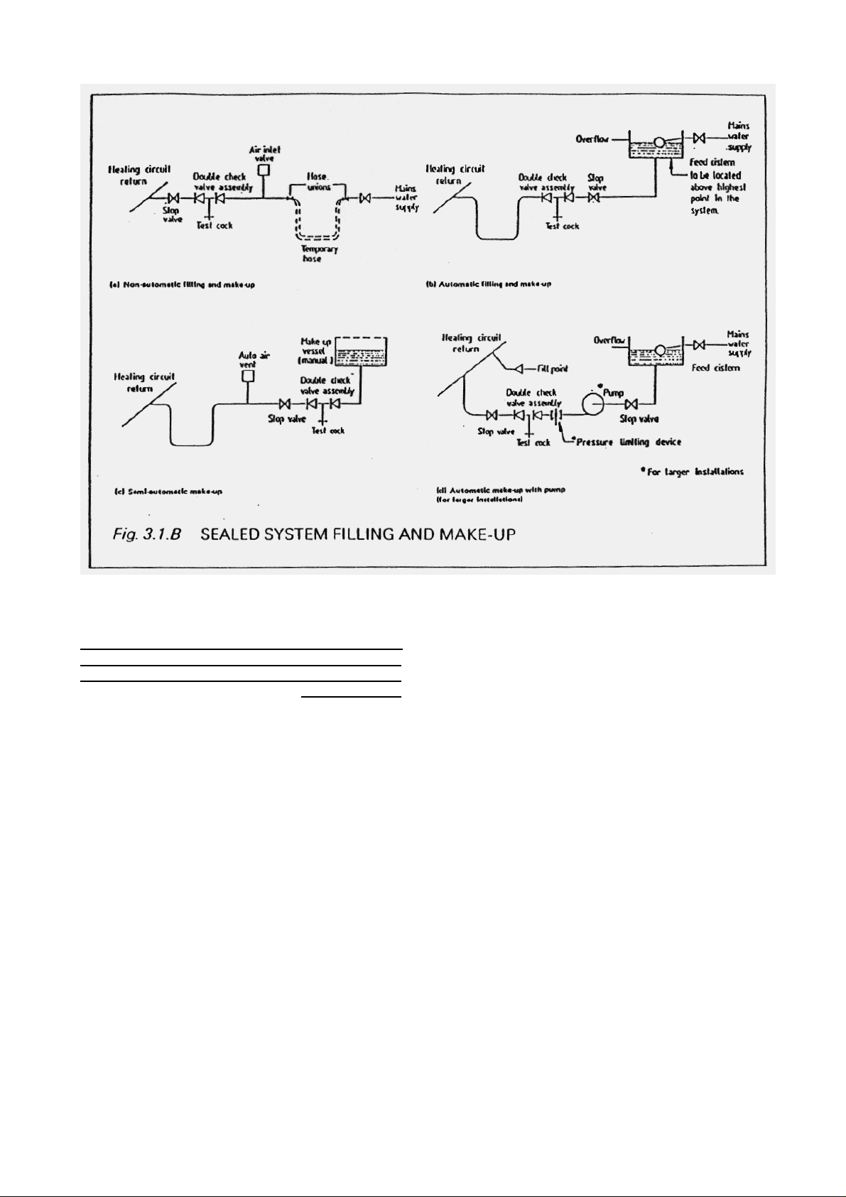
F. Filling the system
A double check valve, stop valve and filling loop are
supplied. Before using ensure that the arrangement
complies with the requirements of the Local Water
Authority. Alternatively BS 5449:1990 (fig 3.1A) shows
other methods of filling.
Fig. 3.1.A ALTERNATIVE TOP UP SYSTEM
G. System make up
There must be no direct permanent connection to the
mains water supply, hence the filling loop must be
disconnected at one end alter use.
If an automatic top up method is required, then this
must be done via either a cistern which has no other
purpose or a top up bottle. Full details are provided in
BS.5449:! 990 (fig 3.1 B) Again, always check local
Water By-laws before installation. See also Fig.3. l.A.
H. Pump performance
Fig.3.2 shows the pump performance characteristics
and values given take due account of the losses
through the appliance.
I. Thermostatic radiator valves
A by-pass is not required and such valves can be fitted
on all radiators if desired.
J. Drain points
Drain taps should be lilted on the lowest point of the
system, the taps complying with BS.2879
K. Vents
Although an automatic air vent & manual air vent is
provided on the appliance, further facility to vent the
system should be provided.
L. All components and fillings used should be
suitable for temperatures of up to 11O°C and pressures
of up to 3 bar.
All syslem components added must be in occoidance
with US 5-149 and BS.G798.
Page 7
Page 8
Position 1
1000
30-
35 016
Position It
170O
45-
60 025 Position III
2450
72.92
038
Speed RPM Watts
Input
Full Load
Current in Amps
Fig. 3-2 PUMP PERFORMANCE
M. Central heating pressure
We recommended that the initial design pressure, i.e. when cold, be 1 bar When fully heated and drawing
a full load, the resultant hot pressure must not exceed 2.7 bar. The safety valve will discharge at 3 bar ± 0.3
bar.
N. System design
A typical sealed system is shown in Fig.3.3.
3.3.2 Domestic hot water circuit
See Fig.3.1 for connections
An extended copper coil is filled which is healed from the primary water. Starting from cold, the appliance
should be fully heated before full capacity hot water supply is obtained
IMPORTANT
To conform to the requirements of the National Water Council, il the main water pressure is at any lime in
excess of 73 psi. (5 bars) {1 69(1) a Pressure Limiting or Pressure Reducing Valve must be fined by the
installer into the mains supply in an inconspicuous approved by Ihe NWC and must not allow more than 73
psi. (5 bars) pressure to the appliance.
Page 8
Page 9
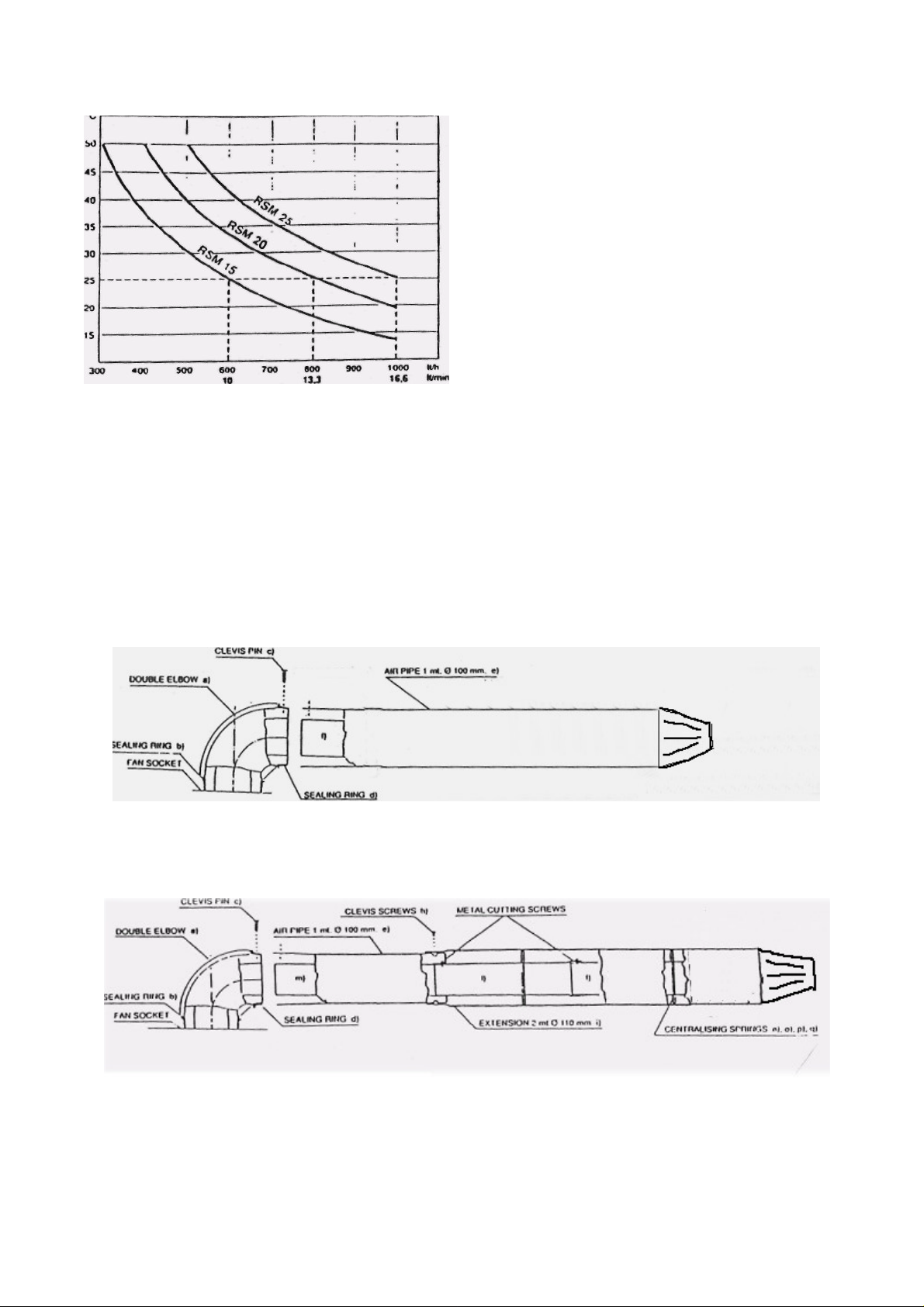
Fig. 3.4 DOMESTIC HOT WATER SUPPLY
3.4 FLUE SYSTEM
3.4.1 The standard balanced flue system can be
directed to the right, left or rear of the appliance.
3.4.2 As supplied, the standard horizontal flue assembly
will cover a distance of up to 910 mm from the centre
line of (he appliance for side flues. for rear flues, a wall
thickness of up to 800mm can be accommodated. Both
dimensions are to the outside wall face.
An optional 1m extension flue system kit (Pan No
R3000050) is available which allows the maximum
lengths to be increased to 1840 mm and 1730 mm
respectively.
An optional 2m extension flue system kit (Pan No
R3000014) is available which allows the maximum
lengths to be increased lo 2840 and 2730 respectively
3.4.4 If a vertical flue is required an optional vertical
flue system kit (Part No R3000030) is available
which replaces the standard 1m horizontal Hue
assembly supplied. The vertical flue assembly will
cover a distance of up to 1m from the top of the
boiler flue hood to the end of the air pipe and comes
complete with a terminal rain hood.
Optional extension flue system kits are available to
allow the maximum vertical lengths lo be increased
lo 1975mm (Part No 3OO0050) or 2975mm (Part No
3000014).
Fig. 3.5 STANDARD HORIZONTAL FLUE SYSTEM KIT COMPONENTS
Fig. 3.6 OPTIONAL HORIZONTAL
EXTENSION FLUE
SYSTEM KIT COMPONENTS
Page 9
Page 10
3.4.5 The flue system must be installed in accordance
with BSS440 Part 1.
3.4.6 Siting of flue terminal
It is essential that products of combustion cannot enter
any building through such as openable windows, doors,
air bricks, etc.
Fig 3.7 gives details of the minimum required spacing of
the 'terminal from building features.
3.4.7 Terminal guard
Where the terminal is fitted within 2m of a walkway. a
balcony or a fiat roof to which people have access, then
a terminal guard, model C.1 must be fitted centrally over
the terminal. This guard is available from KESTON
BOILERS.
3.4.8 Air supply
This appliance is room sealed and. when installed in a
room or space, requires no ventilation. If installed in a
cupboard/compartment, air is required for cooling
purposes, as follows:
Fig. 3.7 SITING OFTHE TERMINAL
Position of Air
Vents
Air from Room
or Internal
Air Direct from
Outside
Space
High level 236 cm²
36-6 ins²
Low level
36.6 ins²
236 cm²
18.3 ins²
1 1 8 cm²
18.3 ins²
1 1 8 cm²
Both air vents must communicate with the same
room or space, or both must be on the same wall to
outside air.
3.5 APPLIANCE LOCATION
3.5.1 This appliance is not suitable for external
installation.
3.5.2 The wall on which the appliance is mounted
must be of suitable load bearing capacity
3.5.3 Installation in a compartment is permitted (full
guidance is provided in BS.6798).
3.5.4 Adequate space must be allowed for installation, subsequent servicing, and safe operation.
Appliance dimensions and the minimum allowable
clearances required are shown in Figs. 3. t and 3.8
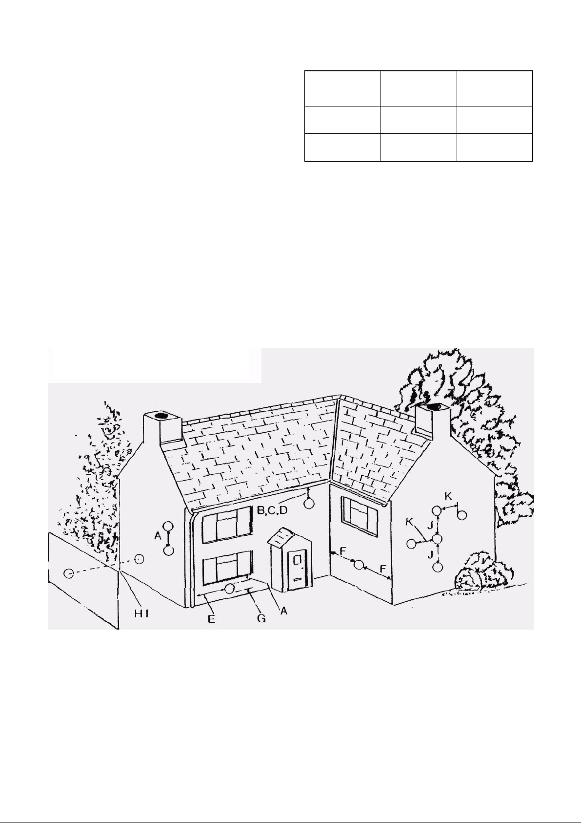
TERMINAL POSITION Minimum distance
Fanned draught.
A. Directly below an openable window or other
opening. e.g. an air brick 300 mm
B. Below gutters, soil pipes or drain pipes 75 mm
C. Below eaves 200 mm
D. Below balcony 200 mm
E. From vertical drain pipes and soil pipes 75 mm
F. From internal or external corners 300 mm
TERMINAL POSITION Minimum distance
Fanned draught.
G. Above ground or balcony level 300 mm
H. From a surface facing a terminal 600 mm
I. From a terminal facing a terminal 1200 mm
J. Vertically from a terminal on the
same wall 1500 mm
K. Horizontally from a terminal on the
same wall 300 mm
Page 10
Page 11
A flexible three-core PVC insulated cable must be
used between the isolator and terminal block with a
minimum cable size of 0.75 mm1 (24 x 0.2 mm)
BS.6500 Table 16
Ensure all cables are secure.
3.6.3 ELECTRICITY SUPPLY
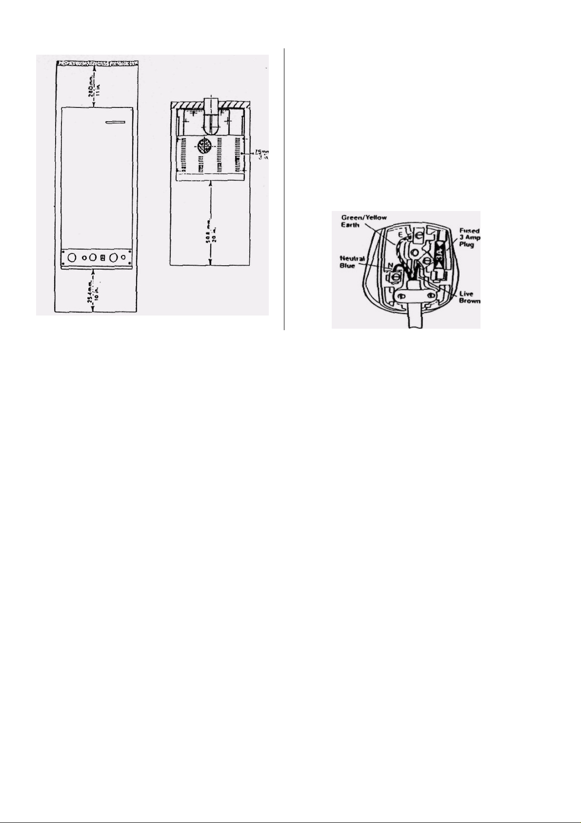
WARNING: THIS APPLIANCE MUST BE EARTHED.
Connection shall be made to a 240 Volts 50 Hz supply. K a mains plug connection is used it must be
of a three-pin type and fused to 3 Amps.
To connect a plug
Fig. 3.8 MINIMUM CLEARANCES
3.5.6 The position must allow for correct termination of the
flue system (see Section 3.4).
3.5.6 The combination boiler may be installed in any room
or internal space, although particular attention is drawn to
the requirements of the current I.E.E. Wiring Regulations,
and in Scotland, the electrical provisions of the Building
Regulations applicable in Scotland, with respect to the
installation of the combination boiler in a room or internal
space containing a bath or shower.
Where a room-sealed appliance is installed in a room
containing a bath or shower, any electrical switch or
appliance control utilising mains electricity should be so
situated that it cannot be touched by a person using the
bath or shower.
3.6 ELECTRICAL
3.6.1 Electrical connections and installation must
conform to current IEE Regulations and. in Scotland, the
electrical provisions of the Building Regulations.
The appliance must be earthed.
Wiring external to the appliance MUST be carried out by a
competent person in accordance with the current IEE
Regulations and Local Regulations which apply. The
Thermornatic Combination Boiler is supplied for
connection to a 240V-50Hz single phase. The appliance is
fused at 3A
3.6.2 The method of connection to the electricity supply
MUST provide means of completely isolating the electricity
supply to the boiler and its ancillary control, preferably by
using a 3A fused three-pin plug and unswitched shuttered
socket outlet both complying with the requirements of 8S.1
363. or alternately a 3A fused double-pole switch having n
3 mm contact separation on both poles.
As the colour of the wires in the mains lead of (he
appliance may not correspond with the coloured
markings identifying the terminals in your plug, proceed
as follows:—
The wire which is coloured green-and-yellow must be
connected to the terminal in the plug which is marked
with the letter E or by the earth symbol or coloured
green or green-and-yellow.
The wire which is coloured blue must be connected to
the terminal which is marked with the tetler:N or
coloured black.
The wire which is coloured brown must be connected to
the terminal which is marked with the letter L or
coloured red.
ELECTRICAL CONNECTIONS
3.6.4 To gain access to the terminal block remove me
four screws fixing (he base panel with the attached front
door and remove the panel (see Fig. 3.10, item 9'1
3.6.5Thread the main supply cable through the cable
restraining clamp, leave enough cable for removal of
control panel to replace any boiler controls.
3.6.6 Ensure earth wire is longer than current carrying
conductors so that if cables are strained or slip in their
anchorage, the current carrying conductors become taut
before the earth wire.
Page 11
Page 12
Page 12
Page 13
4. INSTALLATION PROCEDURES
4.1 Unpack the appliance, check the contents:
Combination
i
boiler
Wall plugs
ii
Fixing brackets
iii
Connection
iv
plate with ball
valves
T-bar template
v
Flue assembly with
vi
elbow
Wall liner with flexible
vii
washer
Filling loop with double
vii
check valve
i
4.2 Select the appliance position, taking due account
of Section 3.
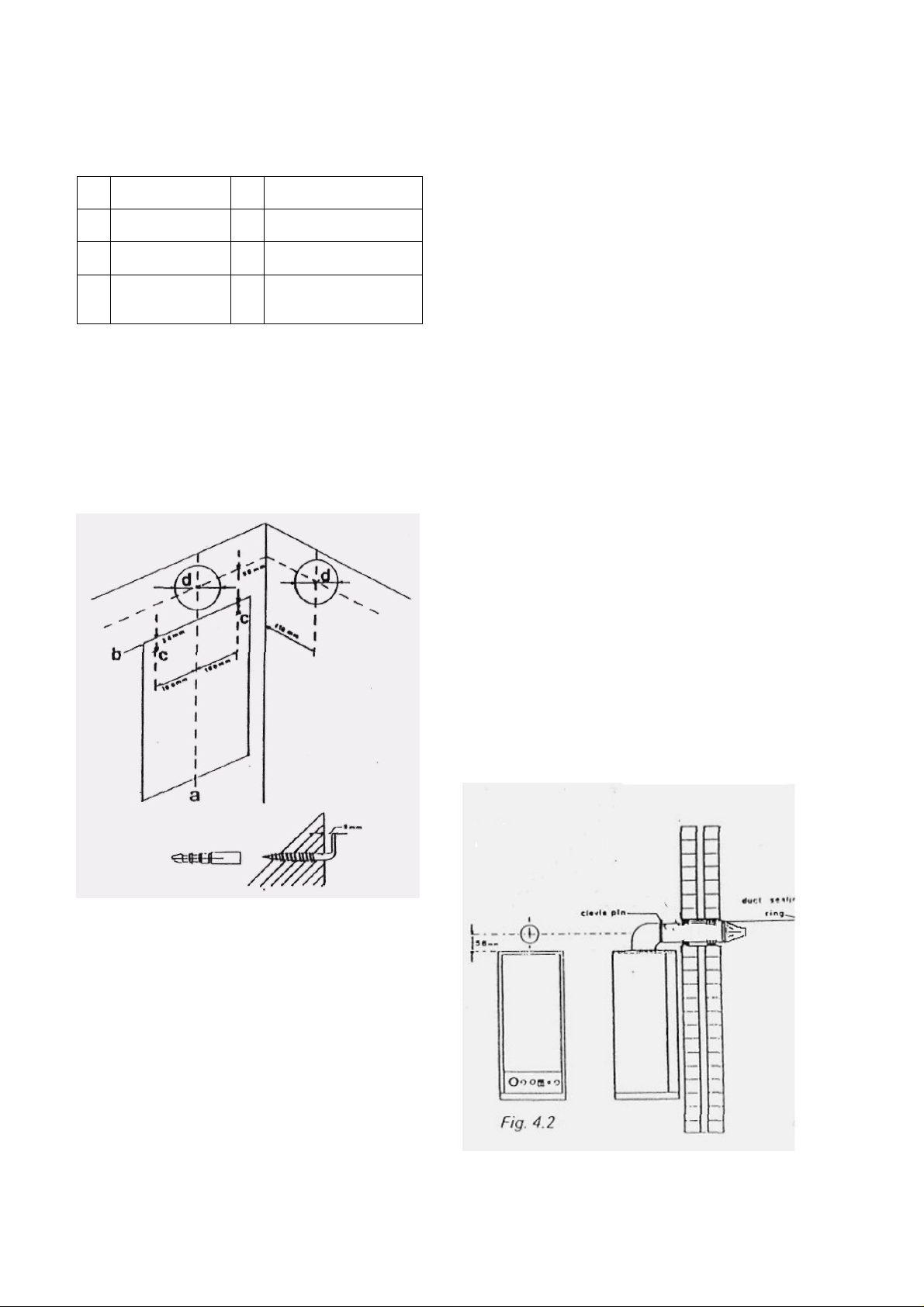
4.3 PREPARATION FOR MOUNTING THE
APPLIANCE
The Thermomatic Combination Boiler is supplied with
a connection plate with ball valves and a T-bar
template that allow the installer to make all water and
f Insert the plastic plugs and screw in the fixing brackets
to within 2 of 3 mm ol the wall face.
4.3 Hang the T-bar template on the fixing brackets
and check that it is perfectly horizontal and seated on
the fixing brackets.
4.4.1 Hang the connection plate carrying the valves on
the T-bar template hung on the wall in 4.4 and fix
together using the screws.
Drill four holes in the wall for fixing the connection plate
to the wall, using the existing holes on the connection
plate as a template.
Fix the connection plate to the wall using lour screws in
the holes drilled.
4.4.2 Once the T-bar template and connection plate
have been fixed securely lo the wall make all the gas
and water connections.
4.4.3 Remove the T-bar template and hang the
appliance on the fixing brackets via the two square cut
outs on the top of the appliance.
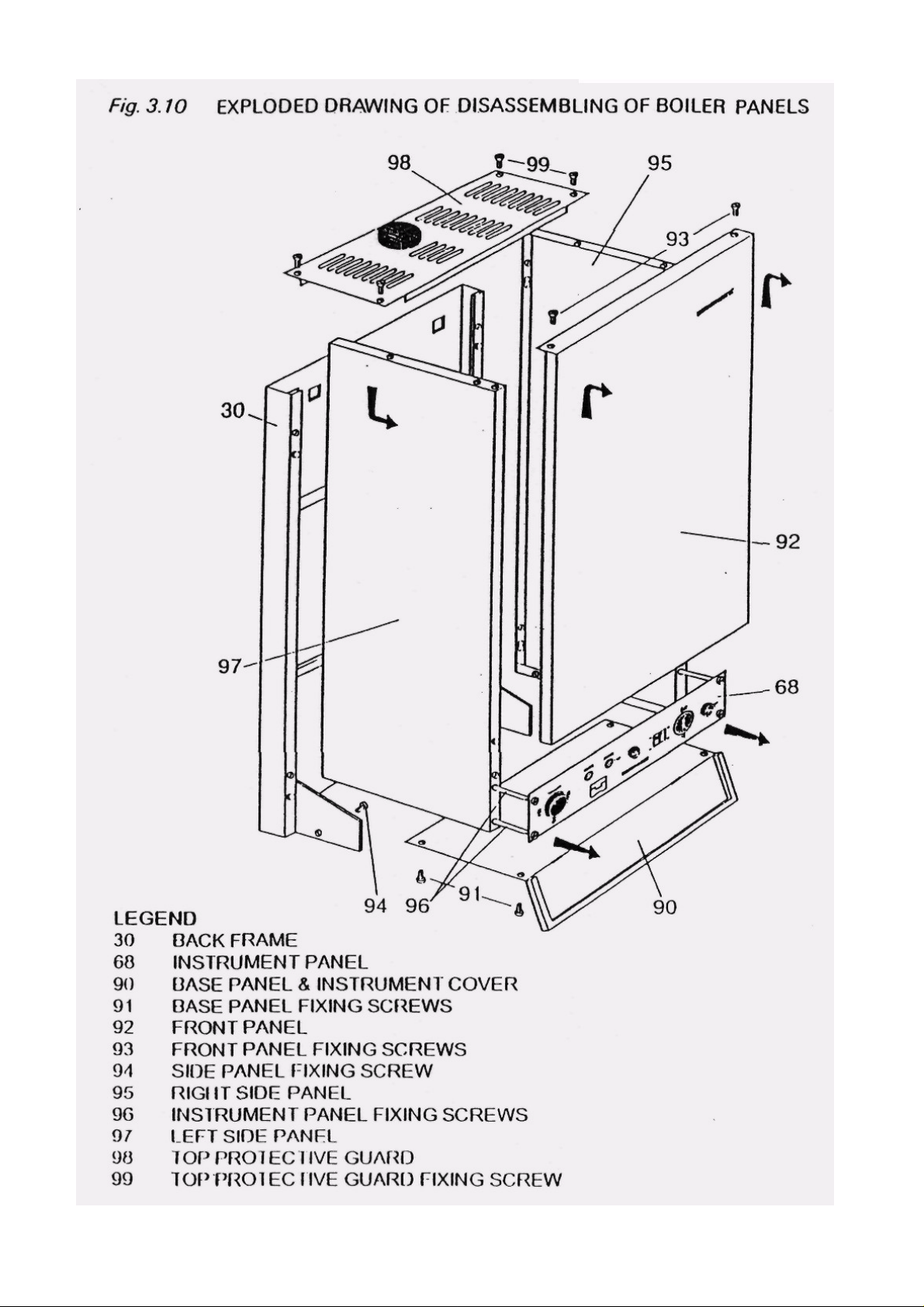
4.5 Remove the base panel. 4 screws (see fig. 3.10
item 91 Exploded drawing of disassembling the boiler
panels).
4.6Remove the front panel. 2 screws (see fig 3.10 item
93). lift and disengage. Remove the plugs from the cold
water inlet and domestic hot water outlet
4.7 FLUE SYSTEM: CUTTING AND ASSEMBLY
4.7.1 Standard Flue Systems
When fully assembled, the standard flue system will be
shown, side or rear flue (fig. 4.2).
gas connections and test the system before hanging
the boiler. Hence, the boiler itself need only be hung
at the final stage of the works.
a Mark a vertical line for the centre of the appliance
b Mark a horizontal line for the top of the appliance.
c Lay the top edge of the T-bar template onto the
horizontal line and mark two holes on the wall for the
fixing brackets.
d Mark the flue hole centre, either on the rear wall.
ceiling or extended to the required side wall as shown.
e For standard flue systems, drill the flue hole 130mm
diameter, preferably using a core drill.
For extended Flue systems, drill the Flue hole 145
mm diameter
IMPORTANT: The plastic liner must always be used
and the air pipe fixed at the appliance elbow ONLY.
Page 13
Page 14
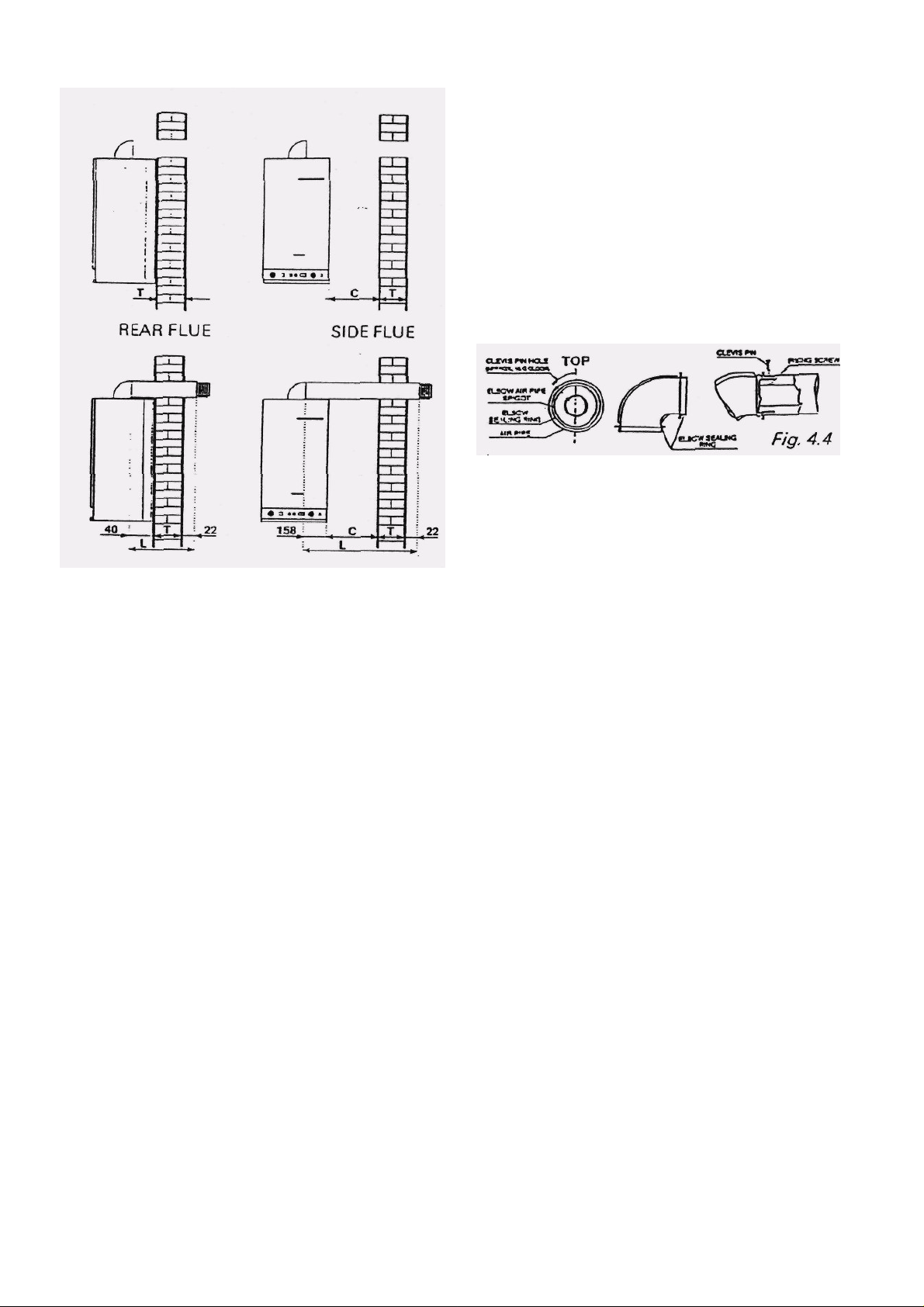
Fig. 4.3
a Measure the wall thickness T (fig. 43).
b Maximum available lengths of plastic liner:
Rear flue Maximum wall thickness (standard liner):
580 mm (T)
Maximum wall thickness (optional extension
liner) 828 mm (T).
Side flue Maximum distance from appliance side to
outer wail face: 680 mm (T+ C)
(with maximum wall thickness T as for rear
flues)
When measuring and cutting, always separate the inner
(flue) pipe wiih terminal from the outer (air) pipe.
c Cut the air pipe fig. 3.5 — cut from the plain end.
Rear Flue To overall length (L) oFT + 62 mm.
Side Flue To overall length (L) ofT + C+ 180mm
When cutting the air pipe, take care not to ovalise it and
remove the internal sharp edges produced when cutting
the pipe.
Drill again a hole (4 mm diameter) at a distance of 7mm
from the pipe end F) Fig 3 5 to [he hole center
d Cut the flue pipe — cut from the plain end.
Any Flue Cut off exactly the same amount as removed
from the air pipe.
Drill again a hole (3mm diameter) at a distance of 16
mm from the end of pipe to the centre of hole
e Cut the plastic- liner (S)
f Insert the flue pipe/terminal F) into the elbow A) and
secure with the specific screw.
g Insert the terminal into the plain, i.e. unchannelled
end of the air pipe E).
h IMPORTANT
Before inserting the air pipe into the elbow. LUBRICATE THE ELBOW SEAL WITH OIL. then insert the air
pipe completely into the elbow.
If the elbow seal is not lubricated, it is not possible to
insert the air pipe into the elbow.
Take care to let the holes correspond, then insert the
clevis pin (fig 4.4).
i Pass the flue/air pipe assembly through the plastic
liner S).
j Fully insert the elbow A) into the fan socket, ensuring
that the elbow seal is correctly located.
k Check that the terminal protrudes the correct amount
from the wall face (fig. 4.3.).
4.7.2 HORIZONTAL EXTENSION FLUE SYSTEM
a Measure wall thickness T (rig. 4.3)
Page 14
Page 15

Maximum distance from appliance side to outer wall
face:.273Qmm (T+ C), or (torn inner wall lace to outer
wall face: 2840 mm.
When measuring and cutting, always separate the flue
pipe with terminal from the air pipe.
b Join air pipe extension to standard pipe, cut the air
pipe extension (I) 110 mm diameter (fig. 3.6).
Cut from plain end to overall length of T + C + 1 80mm.
When culling the air pipe, take care not to ovalize it and
remove the internal sharp edges produced when cutting
the pipe.
c Cut the flue pipe (I) (fig.3.6) —cut from the plain
end:
Any flue: cut off exactly the same amount as removed
from the air pipe.
Drill again a hole (3 mm diameter) at the same distance
from the pipe end as it was before.
d Position the centralising springs n) o) p) q) (fig.3.6) at
about half of each flue pipe extension (I) and (f).
e Insert flue pipe (m) into (I) and secure with the
specific metal cutting screw; then insert flue pipe with
terminal (f) into (I) and secure with the specific screw.
f Insert the air pipe extension onto the standard air pipe
(e). and make sine that (he hole on the air pipe
extension corresponds to the groove on the standard
air pipe
g Insert the extended flue pipe into the extended air
pipe, from the side of bigger diameter (0110 mm).
h Insert the Hue pipe into Ilie elbow and secure it with
the specific screw
m Slip the ducting sealing ring over the air pipe and
position it near the terminal, at about 50 mm from the
air pipe end.
Then see section 4.7.1 k, I. rn. n. o.
4.7.3 VERTICAL FLUE SYSTEM
a Unpack the 1m vertical flue kit (kit VF/1). The
contents should be:
1 off 3060218 Fan socket sealing washer (1)
1 off R3560630 Conical adaptor Ø118/Ø80 with
test point (2)(3)
1 off R3560632 Concentric roof terminal Ø118
length 120cm(4)
1 off Roofing tile(5)
b Preparations:
- Drill a hole Ø130mm on the roof, in axis to the
fan socket. If this is not possible, consider the
above mentioned losses for every bend.
- In relation to the overall length, arrange for the
proper anchorages along the wall where the
flue kit is going to be positioned.
c Installation:
1. Fit the sealing washer (1) onto the fan socket.
2. Fit the conical adaptor (2)(3)m to the fan
socket.
3. In case of extensions, check that in the
sockets of the flue pipe extensions Ø180mm
(7) there are the Ors (6) and that these are
correctly positioned. Measure the overall
length to be realized and, if necessary, shorten
always from the plain end of the pipe
extensions.
4. In case of extension, connect the air intake
extensions Ø118 (8) one to the other, after
having shortened the extensions, if necessary,
of the same size and always from the plain
end of the air intake extension.
5. Insert the so-assembled flue pipe extension
into the air pipe extension, then fit the whole
assembly into the adaptor(2)(3) already on the
boiler.
6. Properly position the roof finishing tile (5) and
insert the terminal (4) into the hole on the roof,
so that the tile remains at the roof outside.
7. Make the sliding air intake pipe of the terminal
to slide upwards, so to leave the flue pipe
uncovered, and insert the flue pipe into the
flue pipe extension already fitted on the boiler.
Then make the sliding air intake terminal pipe
to slide downwards and fit it into the air intake
extension already on the boiler.
8. Anchor the so assembled flue kit to the wall by
means of proper anchorages.
9. Finish the internal wall face around the hole in
the ceiling.
IMPORTANT:
For vertical concentric flue kits shorter than 1
meter and up to 1 meter of length, from paragraph
B) read directly paragraph F).
Page 15
Page 16

If the flue length required falls between 1m and 1975 mm.
reduce the 910 mm length of 110 mm air pipe by the
required amount and remove the same amount from the
plain end of the inner flue pipe.
If the flue length required falls between 1975mm and
2975mm. reduce the 191O mm length of 110mm air pipe
by the required amount and remove the same amount from
the plain end of the inner flue pipe.
NB: The minimum height of a vertical flue is 1 metre.
f Measure a distance of 113 mm from the face of the wall to
the centre of the flue position and drill a hole of 130 mm
diameter through the ceiling or roof above the boiler to
receive the 100 mm diameter pipe or a hole of 145 mm
diameter to receive the 110 mm diameter pipe.
N6: If the ceiling is of a combustible material use a Ceiling
Fire Stop Plate in accordance with the manu- facturers
instruction.
g Wall mount the boiler in accordance with the paras 4.3 to
4.6. leaving a minimum distance of 450 mm above the
boiler.
h Fit the flue and air pipe extension pieces to the flue and
air connections on the top of the Boiler i If the extended
vertical flue kit is not being used continue the procedure
from step q of these Installation Steps.
For extended vertical flues only, (for tm vertical flues skip
steps j to p):
j Fix the wall bracket in the correct position to support the
flue assembly when in place. (See Fig 4.6)
k Separate the flue pipe with the terminal from the 1 metre
length of 1OO mm diameter air pipe.
I Fit the spring clips at equal intervals onto the metre length
flue pipes from the Extended Vertical Flue Kit. m Fit the110
mm x 100 mm reducing adaptor to the plain end of the
metre length of 100 mm diameter air pipe so that the air
pipe contacts the stop pins in the reducing adaptor Use the
reducing adaptor as a template to pre-drill 2 mm diameter
holes and secure using the screws provided.
n Fully engage the 110 mm air pipe to the 110 mm x 100
mm reducing adapter. Again use the reducing adaptor as a
template to pre-drill 2 mm diameter holes and secure using
the screws provided to Fit the flue pipe with terminal to the
remaining Section(s) of flue pipe to form a complete length
of flue pipe. Use the pre-drilled holes as a template to drill
2 mm diameter holes and secure all connection with the
screws provided
p Push the assembled flue pipe through the assem-bled air
pipe so that the terminal is just clear of the air pipe as
shown in Figs 4 8 & 4 9 For 1m and extended vertical flues.
q Slacken off the screws on the detachable flue pipe sleeve
and slide over the end of the flue pipe extension piece
attached to the outer (See fig 4 8)
r Lousely assemble the 110 mm long by 60 mm diameter
distance piece into the open end of the detachable flue
pipe sleeve (See Fig 3)
Page 16
Page 17

Page 17
Page 18

Fig. 4.10 RAIN HOOD ASSEMBLY
s Working from either the roof or floor level, which-ever
is the most convenient, pass the complete flue/air
assembly through the pre-drilled hole(s) in the
ceiling(s). Ensure that the inner flue pipe abuts the
distance piece (See Fig. 4.8).
t Securely fix the flue assembly in position using the
wall bracket fitted in Step 4.3. The outer pipe (air pipe)
must be securely bracketed or strapped if in the roof
space (Roof strapping is not supplied).
4.8 Connect the gas and water services (Fig 3.1)
i Gas: 15mm compression,
ii CH flow and return: 22mm compression
iii DHW in and out: 15mm compression,
iv Safety valve. 1 5mm compression.
4.9 Assemble the filling loop system.
(Refer to Fig 4 11 Filling Loop Assembly)
Loosely connect the flow end of the double check
valve (D) to the matching connection of the 'S'
shaped pipe (E)
Loosely connect the wingnut end of the flexible pipe
(C) to the free end of the double check valve (D)
Having rolled the flexible hose (C) about one turn
the connection point on the heating return ball valve
(F) including one of the fibre washers supplied (B)
Connect the free end of the filling loop assembly to the
filling cock (A) including the other fibre washer supplied
(B). Ensure that the assemble filling loop does not
interfere with the operation of the gas cock (G).
Tighten all connections.
4.70 Connect the electrical supply:
i Thread the main input cable through the cable damp.
ii Connect the cables to terminal block as shown in the
functional flow wiring diagram.
4.11 In preparation for Commissioning, close all
appliance service cocks and isolate the electrical supply.
Fig. 4.11 FILLING LOOP ASSEMBLY
5. COMMISSIONING
5.1- GAS INSTALLATION
Inspect the entire gas installation, including the meter,
purge and test for soundness in accordance with
BS6891.
(Open doors and windows when purging. Extinguish
naked flames and do not smoke.)
5.2 ELECTRICAL INSTALLATION
Preliminary electrical system checks to ensure electrical
safety must be carried out by a competent person (earth
continuity, polarity, short circuit, resistance to earth), if a
fault has occurred on the appliance the fault finding
procedure (Section 7) should be followed as specified.
5.3. WATER INSTALLATIONS
Ensure that the systems, old or new. have been
thoroughly flushed and cleaned without the appliance in
circuit
5.3.1 Connect the appliance to the connection plate
already fixed to the wall and assemble the Tighten all
connections & open all valves
Page 18
Page 19

5.3.2 Fill the central heating circuit (loosen the cap on
the automatic air vent, item 47 Fig. 6.1) &open the
manual air vent below.
5.3.3 Continue to fill until water comes out of the
manual air vent. Dose the manual air vent.
5.3.4 Repeat the process with the manual air vent until
the appliance has been thoroughly vented. If
necessary restore the pressure to about 1.2 bar.
5.3.5 Test the complete system for water soundness
5.3.6 Drain the system to rectify any leaks and refill to
the initial system design pressure venting all radiators.
DO NOT LOOSEN THE VALVE CAP ON THE EXPANSION VESSEL. Set the red pointer on the pressure gauge to the initial system design pressure.
5.3.7 Once filling is complete, ensure the water
supply valve is off, then DISCONNECT THE FILLING
LOOP AT THE OUTLET FROM THAT VALVE.
Permanent connection of the loop is not permitted.
5.3.8 Open all hot taps and allow water in flow until no
air is present. Close the laps.
5.3.9 Check the water supply connections for soundness. Rectify leaks where necessary.
5.4 Fully open the remotest hot tap. and check that
the flow rate is at least 8.8 litres/min.
5.4.1 With all services checked. all valves open,
continue to commission the appliance.
5.4.2 Isolate the electrical supply.
5.4.3 Remove the boiler front panel (Section 6-2.1).
5.4.4 Light the burner {fig 1.1)
i Connect the electrical supply.
ii Select MAX on boiler control thermostat.
iri Select WINTER on the SUMMER/WINTER switch.
iv Turn on the electrical supply and set any external
controls to call for heat
v Select ON on the ON/OFF switch.
The boiler will now go through its ignition sequence
and the green light will illuminate when the burner has
lit.
If the burner fails to light, the appliance will go to
lockout (red light illuminated) In this case the cause is
probably air in the gas supply line. Wait 10 seconds.
Then press the fed button to restart the sequence.
Once lit the appliance will heal the content of the
appliance then commence supplying central heating.
5.4.6. After 10 minutes check that the burner pressure reading is as given in Section 2. If it is not adjust
the pressure as follows (fig.5 J):
Gas Inlet
1
Solenoid inlet and
2
protection
Inlet gas pressure test
3
point
Outlet gas pressure
4
test point
PROCEOURE TO ADJUST THE GAS PRESSURE
TO THE BURNER
Connect a suitable pressure gauge to the burner
pressure test point (fig 51 item G) The pressure
should read 14 mbar.
Remove the black dust cap covering the inlet gas
pressure lest point (fig 5.1 item 8).
Rotate the regulating screw (fig 5.1 item 3) underneath the cap: clockwise will decrease the pressure,
anti-clockwise will increase the pressure.
5.4.7 Open a hot tap fully, the burner will light; green
operating light ON.
5.4.8 Select SUMMER on the SUMMER/WINTER
switch Operating light ON.
5.4.9 Recheck the burner pressure.
5.4.10 Close the hot tap select OFF on the ON/OFF
switch, the burner will extinguish
5.4.11 Remove the' pressure gauge, retighten the
screw.
5.4.12Relight and check for gas soundness of the
appliance components.
5.4.13Reassemble
i Refil the base panel.
ii Relit the (rout panel
5.4.14 Relight the appliance and leave it running
checking that all air is vented, that all radiators
function and that all system controls react to various
demands.
5.5 HAND OVER THE INSTALLATION TO THE
USER
Gas outlet
5
Gas pressure regulatory
6
screw with cap
Control box with first
7
step (ignition flame)
regulatory roller.
Page 19
Page 20

5.5.1 Hand the Users Instructions to the user and
explain how to operate the appliance and any additional controls.
5.5.2 Advise of the precautions necessary to prevent
damage to the appliance and system by frost
5.5.3 Advise that, for continued safe and efficient
operation of the appliance it is recommences that it be
serviced at less; annually.
5.5.4Either hand these instructions to the user or leave
them at the gas meter.
6. REPLACEMENT OF PARTS
6.1 GENERAL
6.1.1 Part numbers — see exploded diagram, fig. 6.1
6.1.2 Isolate the electricity supply and turn off the gas
supply at the service cock (item 31).
6.1.3 Always check for gas and water soundness of
joints broken during Servicing.
6.2 ACCESS
Certain items need to be removed for access:
6.Z1 Front panel
Remove two screws (fig. 3.10. B). lift and disengage.
6.2.2 Top panel
Remove four screws (fig. 3. JO. 8). and remove.
6.2.3Base panel with attached front door.
Remove four screws and remove panel (fig.3. JO. B)
6.2.4Side panels
After having removed the front, top and base panels.
remove the two screws securing the instrument panel
to the respective side panel. Remove the respective
side panel fixing screw Pull down to disengage (fig.3.
10. item 94).
6.2.5 Withdrawal of instrument panel
Open the front door.
Unscrew four screws until firs: section of thread is free.
Withdraw panel forwards (fig. 3.10. A).
6.3 DRAINING WATER CIRCUITRY OF
APPLIANCE
6.3.1 Isolate the circuit via the cocks (item 41 and 33
[2 off]).
6.3.2 Drain the central heating circuit via the safety
valve (item 27).
6.3.3 Drain the domestic hot water circuit via a hot tap.
6.3.4 Whenever the central heating circuit of the
appliance is drained, the pressure in the sealed
system must be restored upon completion of work.
6.3.5 If the DHW isolation cock is closed, it must later
be readjusted to give a flow of 10 litres/minute at any
tap.
6.4 REPLACEMENT
6.4.1 Replacement is always in reverse order to
dismantling unless otherwise stated.
6.4.2 Electrical connections must be remade in
accordance with the wiring diagram. Fig 3.11
6.5 FAN, ITEM 7
6.5.1 Refer to sections 6.1, 6.2.1, 6.2.2 and 6.4 above.
Page 20
Page 21

6.5.2 Disconnect leads at the in line connectors and
remove the earth wire From the top of the appliance.
6.5.3 Remove three screws from the fan mountings,
remove fan,
6.5.4 Tighten mounting screws evenly.
6.6 AIR PRESSURE SWITCH, ITEM 16
6.6.1 Refer to Sections 6.1. 6.2.1 and 6.4 above.
6.6.2 Disconnect plastic lubes from switch.
6.6.3 Disconnect three wires from switch.
6.6.4 Remove two screws from supporting bracket
and remove switch.
6.6.5 Plastic tubes are identified red to red.
6.7 DOMESTIC HOT WATER EXPANSION
VESSEL ITEM 46
6.7.1 Refer to Sections 6.1. 6.2.1. 6.2.2. 6.2.4 (left
hand side panel) 6.3 (drain DHW circuit) and 6.4.
6.7.2 Unscrew the vessel.
6.8 AUTOMATIC AIR VENT. ITEM 47
6.8.1 Refer to Sections 6.1. 6.2.1. 6.2.2. 6.4. (drain-
ing not necessary.
6.8.2 Unscrew vent from hexagon nut.
6.9 CENTRAL HEATING EXPANSION VESSEL.
ITEM 49.
6.9.1 Refer to Sections 6.1. 6.2.1. 6.3 (central heat-
ing) and 6.4.
6.9.2 Release union on the top of the vessel.
6.9.3 Remove vessel.
6 10 BIMETALLIC PRIORITY THERMOSTAT ITEM
43.
6.10.1 Refer to Sections 6.1, 6.2.1, 6.2.2, 6.2.4 (left
hand side panel) and 6.4
6.10.2 Disconnect the leads to the thermostat.
6.10.3 Unscrew the two screws & remove the
thermostat.
Fig. 6-2
Page 21
Page 22

6.12 CIRCULATING PUMP ITEM 24
NOTE: The base section of the pump should never
require replacement. Instructions detail replacement of
the pumphead.
6.13.1 Refer (o Section 6.1. 6.2.1. 6.3 (drain CH circuit)
and 6.4.
6.13.2 Remove electrical cover from pump — one screw.
6.13.3 Disconnect two wires and remove the earth
connection — one screw.
6.13.4 Undo two alien screws and remove pump-head.
6.13.5 When replacing, speed adjuster is at top. Set to
the speed setting previously used.
6.14 THERMOSTATS AND TEMPERATURE /
PRESSURE GUAGE
6.14.1 Refer to sections 6.1, 6.2.1, 6.2.4 (right hand side
panel), 6.2.5 (except Anticondensing Thermostat) and 6.4
Fig 6.4 POSITION OF THERMOSTATS AND
THERMOSTAT PHIALS
Thermometer/pressure gauge only — drain CH circuit
— Section 6.3.
6.14.2 Identify the phial of the thermostat or thermometer to be replaced (fig. 6.4).
6.14.3 Remove the spring clip from the respective
phial boss.
6.14.4 Trace the capillary to the control body.
6.14.5 Safety (overheat) thermostat, item 65
i) Unscrew the reset button cover.
II) Disconnect two leads.
iii) Unscrew locknut and remove thermostat.
6.14.6 Anticondensing thermostat, item 62
i) Disconnect two leads and remove thermostat.
ii) Remove the two screws attaching the anticondensing thermostat to the fixing bracket.
6.14.7 Boiler thermostat, item 61
i) Remove control knob.
ii) Remove two fixing screws.
iii) Disconnect two electrical leads.
6.14.8 Pressure temperature gauge, item 67
I)Unscrew the pressure sensor (Union, item 29).
ii) Depress two plastic clips and push gauge out.
forwards
Fig 6.5 PRESSURE RELIEF VALVE
6.15.1 Refer to Sections 6.1. 6.2.1 (right). 6.2 4. 6 3
(Drain CH circuit) and 6.4
6.15.2 Disconnect the water pressure gauges probe
(placed on the top of the valve).
6.1 5.3 Disconnect the valve from the union on the
respective pipe coming out of the boiler Remove the
valve
WARNING- It is essential to fit a suitable discharge
pipe (1 5mm diameter) 10 the pressure relief valve
Page 22
Page 23

Fig. 6.7 BURNER
6.16.1 Refer to Sections 6.1, 6.2.1, and 6.4.
6.16.2 Disconnect the union of the gas feed pipe to
the burner pipe (item 54) and take the spring away.
Remove the union at the left side of the gas valve
pipe (item 51).
6.16.3 Gently press off the sealing plate (item 55)
from the burner cover.
6.16.4 Remove four screws, lift the cover a little and
move it lo the left until it is disengaged.
6.16.5 Disconnect the electrode leads.
6.16.6 Remove the two screws A (fig 6.7) and
withdraw the burner.
6.16.7 Transfer the injectors (6.17) and electrodes
(6.18) to the new burner. Ensure that the larger
injector is sited in the center burner bar.
6.16.8 When reassembling, ensure that the two
seals, one under the burner cover and the other on
the sealing plate, are in good condition. Respective
positions of the electrode leads are not important —
the electrodes are interchangeable.
6:17 INJECTORS. ITEM 78.
6.17.1 Remove the burner sections 6.16.1 to 6.16.7
above.
6.17.2 Unscrew the injectors
6.17.3 Refer to 6.16.8 when reassembling. Ensure
the larger injector is fitted in the center burner bar.
6.18 FLAME SENSING AND IGNITION
ELECTRODES, ITME 59
It is recommended that these are replaced as a pair.
16.18.1 Gain access to the burner – 6.16.1 to 6.19.9
6.18.2 Remove the fixing screws of each electrode &
withdraw the electrodes.
6.18.3 Refer to 16.16.8 when reassembling.
6.19 ELECTRONIC CONTROL BOX. ITEM 66.
6.19.1 Disconnect leads.
6.19.2 Remove the 2 control box fixing screws and
remove the box. Replace if required.
6.20 GREEN OPERATING LIGHT, ITEM 71 & RED
LOCKOUT BUTTON.
6.20.1 Refer to Sections 6.1. 6.2.1. 6.2.5 and 6.4.
6.20.2 Disconnect the electrical leads.
6.203 Press in catches & push lamp forward to
remove it
6.21 ON/OFF — SUMMER/WINTER SWITCHES
ITEM 69.
6.21.1 Refer to Sections 6.1. 6.2.5 and 6.4.
6.21.2 Disconnect four leads,
6.21.3 Press in catches and push switch forwards.
6.22 FILLING LOOP, ITEM 39.
6.22.1 Refer to sections 6.1. 6.2 3. 6.3 (Drain CH
circuit of appliance).
6.22.2 Disconnect the filling loop at both ends.
Page 23
Page 24

SECTION 7 Fault finding algorithm Thermomatic combination boiler model RSM 20/FB
Carry out initial fault finding checks i.e. check gas, water, electrical system check i.e. earth continuity, resistance
to, short circuit, polarity.
Repeat checks after any servicing / fault finding.
Fig. 7.1. CONDITION 1.
Does the fan motor
start?
Replace the fan
assembly
Is the red light on the
No Yes No
No
instrument panel on (shut
down signal)?
No
Is there voltage to the
boiler (240V)
No
Is there Voltage to the fan
motor?
Yes
Is the motor stuck?
Yes
Release the motor or
replace it.
No
No
Press slightly the red button
(restart). Red light off?
Check the main supply 3 A.
fuse for continuity.
Is the safety thermostat (ST)
open?
Yes Yes
Faulty control box.
Replace it.
Has the reload
button tripped
No
Faulty safety
Thermostat (ST)
Replace it.
Unscrew the black cap of safety
Thermostat and push the button to
restore the contact
Does the programming clock
(PC)(if fitted) call for heat?
Yes
Is the main switch (MS) on?
Yes
Is the boiler htg. regulatory thermostat (HT)
calling for heat?
Yes
Does the differential pressure switch
(DPS) give conent (closed circuit
between between terminal C and
NC)?
Yes
Are the wiring connections
of the DPS controls correct?
Yes
Adjust the time of consent
No
No
No
No
No
for boiler operation
Switch on. If faulty,
replace MS.
Replace HT
Replace DPS
Reset the electrical connections
according to the wiring diagram
Is the control box faulty?
Replace control
No
box.
Page 24
Page 25

Fig. 7.2. CONDITION 2.
The fan motor
starts, does the
burner light up?
Are the connection pipes
to the pressure switch
No
squashed, inverted or
Yes
Is there an obstruction at
See condition 3
the outlet of the flue gas
pipe or the air intake pipe?
Does the differential
pressure switch (DPS)
give consent of air
pressure and close the
Is control box faulty? Replace control box.
Fig. 7.3. CONDITION 3.
disconnected?
No
No
circuit C - No?
Yes
Yes
Yes
No
Yes
Restore the proper
connection according to the
identification clour
Clear the pipes.
Does the fan make few turns
No
Faulty DPS., replace it.
Is there current
(240V) at the fan
Yes
Check the electrical
supply or the 3A fuse.
motor?
No
The fan motor starts and the
red light on the instrument
panel comes on. Does the
burner light up?
Yes
Check the electrical
connections referring
to wiring diagram:
Earth
Live
Neutral
Check that the ignition probe (IP) cable is not disconnected.
Position properly IP with respect to the burner, avoiding any
contact with the metal parts. Is IP operating regularly?
Yes
Wrong electrical connections?
Yes
No
Does the gas
reach the valve?
No Yes Yes
No
Does the valve let
the gas pass
through?
No
Is there voltage
(240V) at the gas
valve?
No
Faulty control box
No
Is there a spark
from ignition
electrode?
No
Replace IP
Is the main gas
cock open?
No
Open it.
Check that there is the proper gas pressure at
valve outlet (tap 6 - gas valve drawing fig 6.1) If
necessary remove the closing cover and adjust
Yes
Yes
Yes
the gas pressure acting on screw 3.
Faulty gas valve. Replace it.
Check the gas valve connections and. if necessary
Verify if the connection cable is disconnected.
Check the electrode position comparing to the
No
Does the control box give the
replace control box.
burner (it must not touch the burner). If
necessary replace the electrode.
ignition spark?
No
Check that the proper
gas procedure reach tap
2 on gas valve (see gas
valve drawing fig 5.1)
Check control box connections. If
necessary replace control box.
Replace control box
Page 25
Page 26

Fig. 7.4. CONDITION 4.
The boiler is properly on. Is
the green operating light on?
Fig. 7.5. CONDITION 5.
When the water temperature
of the boiler exceeds 60ºC
does the circulation pump
start (check without drawing
water).
Yes Yes
See condition 6
Is the green lamp burnt
No Yes
Check the electrical
connections.
Does the room
No No
thermostat (RT) call
for heat?
Is there 240V at the
circulation pump?
Yes Yes
No No
out?
No
Replace it.
Set the room thermostat at a higher
temperature so that it can give consent.
Is the summer / winter
switch (SWS) set on
winter?
Set SWS on
winter
Faulty circulation pump,
replace it.
Set at 60ºC.
Is the circulation
No
1.Swicth off electrical supply.
2. Remove vent plug
3. Apply screwqdriver to slot on shaft
end and rotate each way pushing in
and out until shaft turns freely.
4. Replace vent plug and switch on
electrical supply.
Yes
pump stuck?
Yes
Is the AT set too
high?
Yes
Check control box connections. If
necessary replace control box.
No
Check the summer / winter
switch connections and if
necessary replace SWS.
Does the
Anticondensing
thermostat call for heat?
Yes
Check the mounting of and connections to the
BPT. If necessary replace BPT.
No
Is the biometalic priority thermostat
(BPT) contact closed?
Page 26
Page 27

Fig. 7.6. CONDITION 6.
The circulation pump starts,
do the radiators get hot?
Yes
See condition 7
Is there air in the radiators
or in the htg. system?
Yes
Let the air escape from the
various vents of the htg.
system.
No
Is the non-return valve
blocked?
Yes
Unblock or replace it.
No
Are the htgballafix valves
open?
Yes
Is the boiler full of water?
No
Open the cap of the vent valve
and let the air escape. Can the
boiler and the system get
filled?
No
Is there no water or too low
pressure in the water
supply?
No
I the domestic
water regulatory
ball valve closed?
No
Yes
Yes
Yes
No
Open them
Fill the boiler and the system
up to 1 bar of pressure.
Restore the water
supply.
Open it.
Set the pump on high speed, acting on the
proper button.
No
Is the pump speed sufficient?
Yes
Is the pump head insufficient?
Yes
Set the head variator of the pump at
maximum.
Is the flexible filling pipe
No
Is the AT set too high?
squashed?
No
Yes
Yes
Set it in order or replace
it.
Check the filling loop
valves.
Page 27
Page 28

Fig. 7.7. CONDITION 7.
Is the heating from radiators
sufficient?
A complete maintenance
is necessary.
Yes
Dirty Heat exchanger?
No
Do the thermostats opertate? Do the
thermometer show a wrong temperature? (
the above may happen when the thermostat
probes are removed for servicing and
wrongly fitted into the respective
sheathings.)
Yes
Yes
Is the boiler htg regulatory
thermostat (HT) at maximum?
Is the boiler undersized?
Is gas pressure right?
Thermostat and thermometer
bulbs wrongly fitted into the
respective sheathings on the
Yes
boiler. Insert the bulbs into the
sheathing according to the
Yes
No
drawing.
Yes
No
Set HT at
No
maximum.
Check the heat
requirement.
FWith the burner alight, check that
the gas pressure at valve outlet (tap
6) is right. Adjust gas pressure
acting on screw 3 after having
removed the closing cap. (see Fig
5.2)
No
Insufficient water content of the boiler
or of the htg system.
No
Does the safety thermostat (ST) cut
out below 90ºC?
No
Faulty boiler htg regulatory
thermostat (HT)?
No
The boiler is working. Does the boiler
stop at the temperature set by HT?
No
Yes
Yes
Yes
Restore 1 bar of pressure in
the boiler and in the heating
system (at cold)
Faulty ST replace it.
Replace HT
Faulty thermometer
Yes
Replace the thermometer
/ water gauge.
Page 28
Page 29

Fig. 7.8. CONDITION 8.
Is the dom. water coming out
of the taps hot enough?
Yes
When small flows of dom.
water are drawn (3.5
lt/min) is water too hot?
Yes
Id the boiler htg. regulatory
thermostat (HT) set on max?
Yes
Set HT to position min.
No
Is the rate of hot water flow too
high?
No
Wrong setting of the boiler htg.
regulatory thermostat (HT)?
No
Does the boiler temperature
stop under 70ºC (without
drawing dom. water)?
No
Is there a temperature loss in the
pipeline connecting to the taps?
No
Insufficient gas delivery?
Yes
Yes
Yes
Yes
Yes
To obtain the desired water
temperature adjust the water flow
acting on the cold water inlet cock
(see no 41 exploded drawing)
Set the HT temperature at
maximum.
Replace HT
Insulate the pipeline.
Set the proper pressure to the gas
valve (see gas valvedrwg.) If faulty
replace the gas valve.
Fig. 7.9. CONDITION 9.
Is the dom. water flow insufficient?
No
Is the domestic coil partly
scaled?
Inadequate pressure in the
Yes Yes
water supply?
No
Is the dom. water regulatory
ball valve too closed or dirty?
No
Are the pipeline or the flow
obstructed?
Yes
Yes
Yes
Clean it.
Restore the water supply.
Open more or clean it.
Clean them.
No
Is the domestic coil obstructed?
Yes
Make an antiscaling washing.
Page 29
Page 30

Fig. 7.10. CONDITION 10.
On summer mode, do the
radiators get hot?
Yes
Is the circulation pump
working?
No
Is the non return valve dirty or
faulty?
Yes Yes
Fig. 7.11. CONDITION 11.
Gas products smell?
Is the summer / winter switch (SWS)
on "winter mode"
No
Is SWS faulty?
Yes
Yes Yes
Clean or replace it.
Are the fire tibes of the heat
exchanger and the baffles dirty?
No
Yes
Switch it to "summer
mode"
Replace it.
A complete cleaning is
necessary.
Wrong fitting of the flue pipe or
of the air intake pipe?
No
Wrong installation of the flue
pipe unit?
No
Obstruction of the flue pipe
terminal?
Yes
Yes
Yes
Remove the flue pipe unit,
clean it and fit it properly to the
boiler.
Remove it. Fit properly and air tight
to the boiler according to the
installation manual.
Remove the obstruction and
leave the terminal clean.
Page 30
Page 31

Fig. 7.12. CONDITION 12.
Water Leakage from the
boiler?
Dirty or faulty valve. Let
water pass through the
valve, turning the red knob,
so to clean it. If necessary,
replace safety valve.
Does water escape from the safety
valve as pressure exceeds 3 bars?
Yes
Does water escape during the
heating cycle?
Does water escape from the
Yes
safety valve below 3 bar?
(pressure relief valve)
Does water escape from the
air vent valve?
No
No
No
No
Filling cock dirty , faulty
Yes Yes
Yes Yes
Yes
or does not stand the
pressure?
Too high boiler
pressure?
Is the expansion vessel
discharged?
Does the vessel hold the
pressure?
Faulty air vent valve, replace it.
Clean up or replace the
filling cock.
Decrease the boiler
pressure to 1 bar.
Fill up the vessel to 1 bar
Yes
No
of pressure.
Leaking valve or faulty
membrane. Replace the
vessel.
Is the filling flexible pipe
leaking?
No
Is the water gauge leaking?
No
Is some washer in the hydraulic
system leaking?
Yes
Yes
Yes
Faulty flexible pipe, replace it.
Faulty water gauge, replace it.
Untight or faulty washer.
Tighten or replace it.
Page 31
Page 32

8. ROUTINE SERVICING INSTRUC-TIONS
To ensure continued safe and efficient operation of
the appliance, it is recommended that servicing and
cleaning of the boiler be carried out at regular
intervals by a competent person.
The frequency of cleaning depends mainly on usage,
but generally once a year should be sufficient. Run
the appliance and detect any faults or servicing which
may be required, noting that the heat exchanger and
burner will be cleaned anyway.
WARNING
Before starting any servicing or replacement of components, always isolate electricity supply to appliance
and turn off the gas supply at the service cock.
8.1 ACCESS
Remove the front, top and base panels (see Section
6.2).
8.2 BURNER/ELECTROOES/INJECTORS
8.2.1Remove the main burner (Section 6171 to
6.17.7).
8.2.2 Clean the burner blades with a soft brush.
8.2.3 Check the condition of-the two electrodes.
8.2.4 If required, remove the injectors and blow or
wash through to clear any deposits.
8.2.5 Do not replace the burner at this time.
8.3 HEAT EXCHANGER CLEANING
(HORIZONTAL FLUE SYSTEMS)
8.3.1 Disconnect the pressure tubes from the inner
top panel (a. fig. 8.!)
8.3.2 Disconnect leads a (the in line connectors (b).
8.3.3 Lift and disconnect the elbow from the fan
socket, then pull the flue assembly out of the plastic
liner.
8.3.4 Remove 8 screws (c) and lift away the fan and
inner top panel complete
8.3.5I n turn, remove the baffle from each heat
exchanger tube and clean the tubes with a suitable
brush
8.4 .6 Rotate the fan checking it runs freely
8.3.7 Replace the baffles, the inner top panel/fan and
the flue elbow Connect the leads (polarity immaterial)
and the pressure tubes (red to red)
8 3.8 Clean any debris from the burner chamber and
order
8.4.1 HEAT EXCHANGER CLEANING (VERTICAL
FLUE SYSTEMS)
8.4.1 Disconnect leads at the in line connectors (b
fig 8 1)
Fig. 8.1 TOP VIEW OF THE BOILER
(Without top protective guard)
8.4.2 Remove the three retaining screws down each
side of the Air Pipe Detachable Sleeve and remove
the sleeve.
8.4.3 Slacken off the screws on the Flue Pipe Detachable Sleeve and slide the sleeve up the flue pipe
and remove the 110 mm length flue pipe distance
8.4.4 Disconnect the pressure tubes from (he inner
top panel (See fig 8.1).
8.4.5 Remove 8 screws {c) and lift away the fan and
inner top panel complete.
8.4.6 In turn, remove the baffle from each heat
exchanger tube and clean the tubes with a suitable
brush.
8.4.7 Replace the baffles and rotate the fan checking
it runs freely
8.4.8 Replace the inner top panel/fan.
8.4.9 Replace the flue Pipe Distance Piece and pull
the flue pipe detachable sleeve back down the flue
pipe until the sleeve covers the top 30 mm of the flue
pipe immediately below the distance piece. Place the
two piece of the air pipe detachable sleeve over the
gap in the air pipe, replace the screws and tighten.
8.4.10 Connect the leads (polarity immaterial) and
the pressure tubes {red to red).
8.4.11 Clean any debris from the burner chamber
and reassemble the remaining components in
reverse order.
8.5 Clean or replace any other components
considered necessary (Instructions for removal are
given in Section 6).
8.6 Relight and check for gas and water soundness
of appliance components.
8.7 Reassemble the appliance casing
Page 32
Page 33

Page 33
Page 34

SHORT SPARE PARTS LIST THERMOMATIC COMBINATION GAS BOILER
MODEL RSM 20/FB
Key
No
Code
62 3020114
Part
Denomination
Aniticondensin
g Thermostat.
Key
No
67 3130201
Code Part Denomination
Overheat
65 3120112
Safety
Thermostat
27 3330342
Temperature &
Pressure Guage
Pressure Relief
Safety Valve
61 3023115
69 303201
Boiler Heating
Regulatory
Thermostat.
On / Off
Summer /
Winter Switch
100 3063287 Inspection Glass
7 R.3000013 Fan Motor
24 3033101 Circulating Pump
Page 34
Page 35

SHORT SPARE PARTS LIST THERMOMATIC COMBINATION GAS BOILER
MODEL RSM 20/FB
Key
No
8 3063218 Sealing Ring.
Code
Part
Denomination
Key
No
43 3424110
Code Part Denomination
47 3330343
70 3520131
Automatic Air
Vent Valve
Operating Light
Neon Bulb.
59 3450113
71 3020157 Lamp Holder
49 3030315
C.H. Expansion
Vessel
Bimetallic Priority
Thermostat
Electrode
(Interchangeable)
53 3544410 Gas Control Valve
16 3063325 Air Flow Switch
66 3523110 Control Box
46 3033315
Domestic Water mini
Expansion Vessel.
Page 35
Page 36

SHORTSPART PARTS LISTTHERMOMATIC COMBI GAS BOILER MODEL
RSM20/FB
Key No CODE PART DENOMINATION
7 R3000013 FAN MOTOR (240Volls)
B 3063218 SEALING RINGS
16 3063325 PRESSURE SWITCH
23 3030341 WASHER FOR WATER CIRCULATOR
24 3033101 WATER CIRCULATOR
27 3330342 SAFETY VALVE TYPE 31 41
31 3033322 GAS COCK TYPE 45
38 3033320 DOUBLE CHECK VALVE'ALBIFIL
40 3033317 FILLING BALL VALVE'ALBIFIL
43 3424110 BIMETALLIC PRIORITY THERMOSTAT
46 3033315 INOX MINI VESSEL
47 3330343 AUTOMATIC AIR VENT
49 3030315 CH. EXPANSION VESSEL 8 LITRES
53 3544410 GAS VALVE
59 3450113 ELECTRODE
61 3023115 HEATING THERMOSTAT
62 3020114 ANTICONDENSING THERMOSTAT
65 3120112 OVERHEAT SAFETY THERMOSTAT
66 3523110 CONTROL SOX
67 3130201 THERMOMETER/WATER GAUGE
69 3033201 DOUBLE SWITCH (Main and Summer/Winter)
78 R3590M20 INJECTORS FOR NATURAL GAS (NG)
R3590G20 INJECTORS FOR LIQUID PROPANE GAS (LPG)
R3000014 OPTIONAL 2M EXTENSION FLUE SYSTEM Kl f
100 3063287 INSPECTION GLASS
Page 36
Page 37

Complete boiler wiring schematic.
Page 37
Page 38

New Thermomatic wiring diagram as from S/No. 00054
When wiring the boiler in conjunction with a time
switch, remove the link plug from the 5 wire block,
(left hand side at the bottom).
Page 38
Page 39

Examples of standard wiring connections to most popular models.
Page 39
Page 40

Page 40
Page 41

Addendum to existing manual.
REGULATION OF THE GAS PRESSURE TO THE NOZZLES
The Thermomatic boilers are delivered already prepared for the required gas, with the gas supply pressures
showed by the specific label slicked inside the front door panel, and also by the scheme of technical data in the
installation instructions (see page 1).
l)First of all check that the available gas and the supply pressure correspond to those for which the boiler has
been prepared.
Should it be necessary to do some adjustment (for example if the supply pressure is another than the
mentioned one (see the specific label), precede as follows:
2)Connect a suitable pressure gauge to the burner pressure test point on the gas control valve (n° 6 in the gas
control valve drawing).
3)Remove the screw cap that covers the gas pressure regulatory screw (6). With the help of an octagonal
screwdriver, turn the regulatory screw (6) until the same burner pressure as shown by the scheme of technical
data (page 1) is achieved:
-turn to the right to decrease the gas pressure;
-turn to the left to increase the gas pressure.
Page 41 (A1)
Page 42

HORIZONTAL CONCENTRIC FLUE EXTENSION FOR RSM20/FB
Identification nr R3501693
In addition to the standard Horizontal Concentric Flue Kit id.n° R3501613 supplied with the boiler, on request
an Extension Kit 1 mt. long (id.n° R3501693) is available.
Important: maximum linear length 3 mt. after the flue elbow;
for every 45° flue elbow consider 0.5mt less;
for every 90° flue elbow consider 1 .Omt less.
The Extension Kit for RSM20/FB id.n° R3501693 consists of:
- Imt. air intake pipe 0100mm. (see n°8 in the enclosed drawing).
- Imt. flue gas ejection pipe 060mm. (7) with centralising spring (9).
- Sealing washer 0100mm. (6) with fixing clamp (10).
On Request:
-R3566490 90° elbow 0100mm/60mm without test points;
-R3566445 45° elbow 0100mm/60nim without test points.
PREPARATION
1 )Remove the elbow (4) after having loosened the respective fixing clamp (10), then remove the standard
concentric flue kit Imt. long.
2)Fit the ORs (3) and sealing washers (2) to the flue elbow (4), and then fit the elbow onto the fancsocket (1)
on the top of the boiler.
3)Drill a hole 110mm of diameter through an outer wall, in line with the flue bend (4) (see also the dimensions
in the Boiler Installation Instructions).
INSTALLATION
l)Properly position the centralising springs (9); insert the flue pipe extensions 060mm (7) one into the other
and then into the standard flue pipe (5).
Shorten, if necessary, always from the plain end of the pipe.
2)Position the sealing washer for pipe junction 0100mm (10) on one end of each air pipe extension
0100mm (8).
3)Fit the air pipe extensions (8) one to the other; properly position the sealing washer (6) on each pipe
junction and tighten it by means of the specific clamp (10).
In case of shortening, cut the air intake pipe of the same length as the flue pipe.
4)Fit the extended flue pipe into the extended air pipe.
5)Fil the wall finishing washer (11) onto the end of the assembled concentric duct.
6)Insert the extended duct into the hole through the wall; make the air pipe slide a little, then fit the flue pipe
into the concentric flue elbow (4).
7)Approach the extended air duct to the flue elbow; properly position the sealing washer (6) and then fix the air
duct to the elbow by means of the fixing clamp (10).
8)Properly finish the internal wall face by means of the wall finishing washer (11).
Page 42 (A2)
Page 43

Horizontal Concentric Flue Extension for RSM20/FB - Legend:
1. Fan socket
2. 3060218 Flue elbow sealing washer
3. 3566291 O-Rings (2 pcs.)
4. 3566290 90° Flue elbow 0100/60 with test points
5. 3566294 Imt Flue ejection pipe 060 (included in the standard flue kit)
6. 3566292 Sealing washer for air pipe junction
7. 1 mt Flue pipe extension 060
8. Imt Air pipe extension 0100
9. 3566296 Centralising spring
10.3566293 Sealing washer fixing clamp for pipe junction
11.3566297 Finishing washer for internal wall face
12.3566295 Imt Air pipe 0100 (included in the standard flue kit)
13.3566299 Anti-wind terminal
14. 3566298 Finishing washer for external wall face
On Request:
R3566490 90° Concentric elbow 0100/60 without test points
R3566445 45° Concentric elbow 0100/90 without test points
Page 43 (A3)
Page 44

PRESSURE RELIEF VALVE:
-Remove the front and the right panels. Then empty the boiler.
-Unscrew and remove the pressure relief valve.
HONEYWELL GAS CONTROL VALVE:
-Close the gas cock in the boiler.
-Remove the front panel.
-Unscrew the fixing screw and remove the electronic control box from the electrical connector on
the gas control valve.
-Unscrew the gas inlet and outlet connections from the gas control valve and remove the valve.
-If the valve needs to be replaced, unscrew the small flanges at the gas inlet and outlet, and fit
them to the new valve.
Warning:
When fitting the small flanges back, take care to fit the flange with calibrated hole at the gas outlet
side of the gas control valve.
WATER CIRCULATING PUMP:
-Remove the front and the right panels, then empty the boiler.
-Unscrew the specific screws and open the electrical contact cover on the pump.
-Disconnect the electrical contacts, included the earth contact.
-If necessary, unscrew the two screws that fix the pump body.
Important:
Check that the pump be set at a velocity that suits the system.
EXPANSION TANK:
-Remove the front panel and empty the boiler.
-Unscrew the connection and remove the tank, taking care to cause no damage to the washer.
HONEYWELL ELECTRONIC CONTROL BOX:
-Remove the front panel.
-Unscrew the fixing screw and remove the box from the electrical connector on the gas valve.
-Disconnect the electrical connector of the control box.
Important:
When fitting the box back, do not forget the insulating washer which must be fitted underneath
the box.
ANTI-CON DENS ATE THERMOSTAT:
-Remove the front and the right panels.
-Disconnect the electrical contacts.
-Remove the thermostat probe (see drawing at page 15).
-Unscrew the two fixing screws and remove the thermostat.
Important:
When fitting the thermostat back, take care to carry out the electrical connections following
exactly the wiring diagram (see page 9).
HOT DOMESTIC WATER PRIORITY THERMOSTAT:
-Remove the front panel and disconnect the electrical contacts.
-Unscrew the two fixing screws and remove the thermostat.
AUTOMATIC AIR VENT VALVE:
-Remove the front panel and, if necessary, also the top cover.
-Unscrew and remove the vent valve.
Page 44 (A4)
 Loading...