

Page 1
Prefabricated Plant Rigs
Installation & Control
Instructions
34 West Common Road
Hayes, Bromley, Kent BR2 7BX
Tel. +44 (0)20 8462 0262 Fax. +44 (0)20 8462 4459
Email : info@keston.co.uk web : www.keston.co.uk
Page 2
WD309/0/2003 The Keston Prefabricated Plant Rigs
1.0 INTRODUCTION
The Keston Pre-Fabricated Plant Rigs are designed as complete heating plant
packages for rapid site installation and commissioning. The units are supplied
to site pre-piped and pre-wired on a floor standing frame (a wall hung option is
available for the two boiler rigs). The rigs are supplied complete with a Keston
Rig Controller module.
2.0 PIPE CONNECTIONS
Although most pipework is already complete within the rig. The final
connections for gas, condensate, flue exhaust and air supply will need to be
made to each boiler. The connections should be made following all
requirements laid out in the boilers Installation & Servicing Instructions.
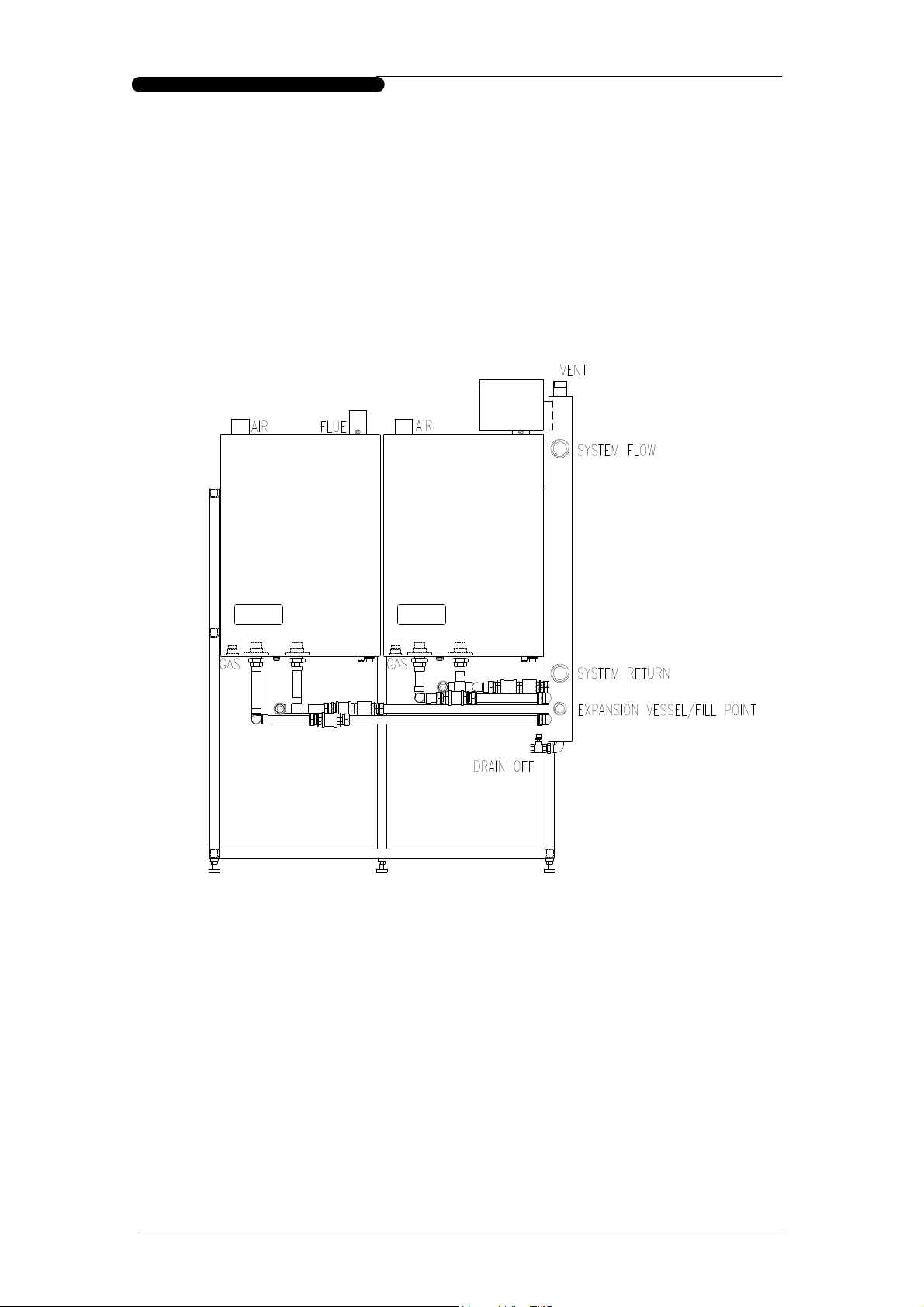
The rigs are provided complete with a balance header which is prepiped to
each boiler. A pair of system tappings, flow and return, are provided on the
header plus connection points for fill point, expansion vessel, air vent and
drain off. The diagram below shows the relative position of these connection
points and their intended purpose.
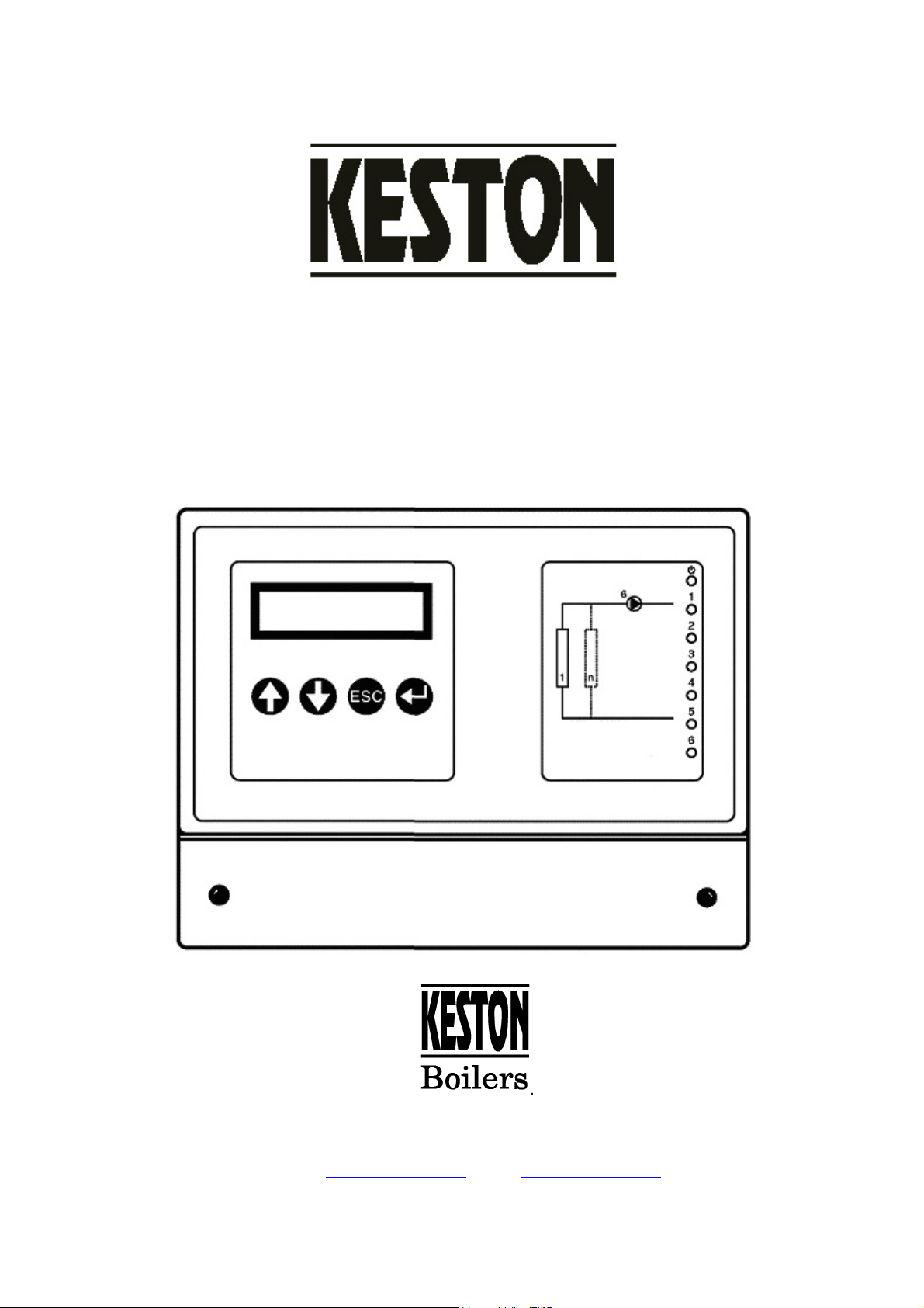
3.0 CONTROL MODULE
The Keston Rig Controller is a comprehensive controller offering a wide range of
facilities to the end user. However, it is recognised that customers control
requirements vary widely and that some functions are not always required. The rigs
are supplied preset for option 1) Basic Sequence Control. To enable modes 2), 3) or
4) additional sensors may be required. In addition, commissioning set-up will be
required by Keston Boilers Ltd, or its approved agents.
Installation & Control Instructions
Page 2 of 10
Page 3

WD309/0/2003 The Keston Prefabricated Plant Rigs
3.1 AVAILABLE FUNCTIONS
To enable simple application the functionality is divided into four distinct groups as
detailed below:
3.1.1 Entry Level (Factory Default)
This is the mode in which all rig controllers are set by the factory, and therefore no
further components or action are necessary to realise these facilities.
Boiler Sequencing
In this mode the controller sequences the operation of the boilers to ensure the
required flow temperature is maintained with the minimum boiler operation. The
required flow temperature is set by the user.
Boiler Load Averaging
The switching order of the boilers is changed once per week, based on the hours
each boiler has run, to ensure even usage of each boiler over time.
Frost Protection
The Controller also provides frost protection, which will fire the boiler(s) in the
event the main flow temperature falls below 5OC. The boiler will remain on until
the flow temperature is raised above 15OC.
System Pump Overrun & Seizure Protection
The controller also provides a 230VAC output for connection to a system pump.
The pump is run when the rig is enabled and will also provide a 2 minute overrun
on shutdown. The controller will also operate the system pump at least once daily
to prevent seizure.
Fault Signal
A volt free pair of contacts are provided which move the closed circuit in the event
of a fault being identified
Control Signal
The Controller will fire the boiler(s) when enabled via a volt free contact pair.
3.1.2 Compensated Heating & Time Control
This mode provides all the features detailed in “Basic Sequence Control” plus the
additional features detailed below. However, to access this mode an outside
temperature sensor (part no C.17.4.17.00.0) is required. These are available from
Keston Boilers Ltd via your preferred stockist.
Weather Compensated Heating Control
The boiler flow temperature is adjusted automatically according to the outside
temperature. This provides even building temperatures and maximises boiler
efficiency.
Comprehensive Heating Time Control
The controller features an integral time programmer for heating periods permitting
a different heating pattern for each day of the week with up to two heating periods
per day. Holiday dates can also be programmed. The user may then specify three
temperature levels – day, night and holiday. The room temperature is estimated
based on outside temperature, boiler flow temperature and the building
construction.
DHW Override
In the event a volt free signal is received from the hot water system the weather
compensated heating control is suspended and the unit runs at the specified flow
temperature until the volt free signal is removed.
Outside Temperature Frost Protection
The outside temperature is constantly monitored such that, in the event the
outside temperature falls below 3OC the boiler is fired to maintain a boiler flow
temperature of 20OC. Once the outside temperature rises to 4OC or above this
action is stopped. This feature is design to ensure protection of system pipes
against freezing. However, it can be disabled if required.
Installation & Control Instructions
Page 3 of 10
Page 4

WD309/0/2003 The Keston Prefabricated Plant Rigs
3.1.3 Full Room Temperature Modulation
This mode provides all the features detailed in “Basic Sequence Control” and
“Compensated Heating & Time Control” plus the additional features detailed below.
However, to access this mode a room temperature sensor (part no C.17.4.31.00.0) is
required. This is available from Keston Boilers Ltd via your preferred stockist.
Accurate Room Temperature Control
The controller constantly monitors the room temperature to ensure that the
requested room temperature is maintained without deviation. The boilers are
directly controlled in terms of output and temperature to ensure this is achieved.
Optimum Start Control
During non-heating times the room temperature, and outside temperature, are
constantly monitored to identify the latest time at which the boilers can be fired to
riase the room temperature to the required temperature at the required time.
Room Frost Protection
The room temperature is constantly monitored such that, in the event the room
temperature drops to 3OC or less the boiler is fired at the minimum boiler flow
temperature until the room reaches 5OC.
3.1.4 Communication Options
For installations where additional control and monitoring is required the Keston Rig
Controller offers a wealth of communication options as follows:
Multiple Rig Control
Up to 150 boiler rigs, each with four boilers, may be connected and controlled
from a single controller which is designated as the “Master” controller
Fax Modem
A modem may be connected to the controller. The controller may then be
configured to send a status report by fax once per week. In addition, the
controller may be configured to send a fault report by fax should an fault occur on
a boiler or a sensor.
Remove PC Link
A windows software package is available to enable remote monitoring and control
of rig controllers via modem link or direct connection via RS232 cable.
Hours Run Data
The unit can be interrogated to identify the hours of operation of each boiler, at
high and low fire rates, and the system pump.
Datalogging
The integral data logging can be interrogated to provide details, at 5 minute
intervals, of boiler operations, pump operation and sensor readings over a period
of up to 7 days.
3.1.5 Other Configuration Options
The controller is configured at the factory for what is considered to be the most
popular configuration options. However, Keston Boilers Ltd, as part of the optional
commissioning process can reconfigure to suit specific customer requirements.
Specific options include:
Variations to system pump overrun timings.
Specification of up to 8 holiday periods during which the system will be
maintained at a lower temperature.
Changing the volt free input to provide timer override or forced holiday mode.
3.1.6 Keston Chronotherm Room Controller
For user control of room temperature levels and operating times a Keston
Chronotherm room controller (part no C.17.4.21.00.0) may be connected to the
Keston Rig Controller. Using the same user interface as a standard programmable
room thermostat, this controller will allow override and re-programming of switching
times and heating levels by the building occupant form within the heated area.
Contact Keston Technical Department for further details of this option.
Installation & Control Instructions
Page 4 of 10
Page 5

WD309/0/2003 The Keston Prefabricated Plant Rigs
4.0 ELECTRICAL CONNECTIONS
This section details the actions required to implement to control level required:
4.1 Basic Sequence Control (Factory Default)
Electrical Connection
a) A 230VAC 5A supply is required and should be wired to the switched spur
unit mounted near the rig controller on frame. This power supply will serve
the controller, the boilers and the system pump.
b) The electrical cover at the base of the Rig Contoller should be removed to
expose the wiring connection points.
c) The following user connections should be made (refer to the diagram above)
a. The external controls should generate a volt free signal (closed on
demand) which should be connected to pins 6 and common on the rig
connection strip
b. The system pump may be connected to the vacant live (L) and (N)
connections on the rig connection strip. This will also provide a pump
overrun facility and anti-seizure operation of the system pump in periods
of inactivity
c. Rig connection strip terminals 1 and 2 will provide volt free alarm signal
(closed on alarm) for remote alarm indication
NB: The resistor factory fitted between terminals 4 and common should be left in
place.
Installation & Control Instructions
Page 5 of 10
Page 6

WD309/0/2003 The Keston Prefabricated Plant Rigs
4.2 Compensated Heating & Time Control
Electrical Connection
a) A 230VAC 5A supply is required and should be wired to the switched spur
unit mounted near the rig controller on the frame. This power supply will
serve the controller, the boilers and the system pump.
b) The electrical cover at the base of the Rig Controller should be removed to
expose the wiring connection points.
c) The resistor factory fitted between connection strip terminals 4 and common
should be removed and discarded.
d) The following user connections should be made (refer to the diagram above)
a. The system pump may be connected to the vacant live (L) and (N)
connections on the rig connection strip. This will also provide a pump
overrun facility and anti-seizure operation of the system pump in periods
of inactivity.
b. Rig connection strip terminals 1 and 2 will provide volt free alarm signal
(closed on alarm) for remote alarm indication.
c. The external temperature sensor (which must be mounted outside the
building on a north facing wall, not in direct sunlight) must be connected
to terminals 4 and common. Screened cable must be used. The cable
screen must be connected to the earth terminal.
d. A heating override signal (ie from a hot water calorifier) may be
connected as a volt free signal to terminals 6 and common. This signal
will cause the rig to provide a constant 80OC flow regardless of heating
and outside temperature demand. The 80OC flow setting can be adjusted
to a lower temperature if required.
Installation & Control Instructions
Page 6 of 10
Page 7

WD309/0/2003 The Keston Prefabricated Plant Rigs
4.3 Full Room Temperature Modulation
Electrical Connection
a) A 230VAC 5A supply is required and should be wired to the switched spur unit
mounted near the rig controller on the frame. This power supply will serve the
controller, the boilers and the system pump.
b) The electrical cover at the base of the Rig Controller should be removed to
expose the wiring connection points.
c) The resistor factory fitted between connection strip terminals 4 and common
should be removed and discarded.
d) The following user connections should be made (refer to the diagram above)
a. The system pump may be connected to the vacant live (L) and (N)
connections on the rig connection strip. This will also provide a pump
overrun facility and anti-seizure operation of the system pump in periods
of inactivity.
b. Rig connection strip terminals 1 and 2 will provide volt free alarm signal
(closed on alarm) for remote alarm indication.
c. The external temperature sensor (which must be mounted outside the
building on a north facing wall, not in direct sunlight) must be connected
to terminals 4 and common. Screened cable must be used. The cable
screen must be connected to the earth terminal.
d. The room temperature sensor (which must be mounted in a common
area without thermostatic radiator valves fitted) must be connected to
terminals 5 and common. Screened cable must be used. The cable
screen must be connected to the earth terminal.
e. A heating override signal (ie from a hot water calorifier) may be
connected as a volt free signal to terminals 6 and common. This signal
will cause the rig to provide a constant 80OC flow regardless of heating
and outside temperature demand. The 80OC flow setting can be adjusted
to a lower temperature if required.
f. The controller will require a change to its configuration settings to
recognise the additional room sensor – See section 5.4.
Installation & Control Instructions
Page 7 of 10
Page 8

WD309/0/2003 The Keston Prefabricated Plant Rigs
4.4 Communication Options
The communication options features can be implemented by Keston Boilers Ltd in
conjunction with options 1, 2 or 3. For implementation a telephone line port will be
required in close proximity to the rig. This is for installation of a communications
modem which is supplied and fitted by Keston Boilers Ltd as part of the
implementation procedure.
5.0 CHANGING THE SETTINGS
The default mode of the controller does not permit changes to any of the settings,
including date and time. This is to prevent inadvertent changes by the user. To
permit changes to time and temperature settings the access level must be set to level
2 as follows:
a) Press the “ESC” button repeatedly until the first line of the display shows
“Function 001-x” (where “x” is a letter).
b) Press the up arrow repeatedly until the top line of the display shows
“Function 001-A”.
c) Press the “↵” button once then press the “↓” button repeatedly until the
display shows “Access Level”.
d) Press the “↵” key twice so that the current access level number starts
flashing.
e) Enter the key sequence ↑ ↓ ESC ↵. The access level number will now
change to 2.
f) Press “ESC” repeatedly until the display returns to “Function 001-A”.
The controller is now set to allow changes to time and temperature settings.
5.1 Changing the date and time (all options)
a) Set the Access Level 2 (detailed in section 5.0).
b) Press the “↓” button repeatedly until the top line of the display shows
“Function 001-A”.
c) Press the “↵” button once.
d) Press the “↓” button until the display shows the date and time.
e) Press the “↵” button and the day will start to flash. Adjust the date setting
using the “↑” and “↓” buttons. Press “↵” to store the new setting.
f) Repeat the procedure for the month, year, time, etc.
Installation & Control Instructions
Page 8 of 10
Page 9

WD309/0/2003 The Keston Prefabricated Plant Rigs
5.2 Adjusting the flow temperature when firing due to an external demand signal (all
options)
This temperature is factory set to 80OC. Contact Keston Boilers Ltd for changes to
this setting.
5.3 Modifying the heating on times (options 2, 3 and 4 only)
a) Set the Access Level 2 (detailed in section 5.0).
b) Press the “ESC” button repeatedly until the top line of the display shows
“Function 001-x” where “x” is a letter.
c) Press the “↑” button until the display shows “Function 001-B Plant Control”.
d) Press the “↵” once and then press the “↑” repeatedly until the display shows
“Time Clock”. Press “↵” once.
e) Select the day of the week you wish to change using the “↑” and “↓” buttons.
f) Press the “↵” one so that the first on time flashes. Set the on time to the
desired time using the “↑” and “↓” buttons. Press “↵” to store the new setting.
g) Repeat the operation for the first off time and the second on and off times.
h) Go to step e) for other day settings.
Installation & Control Instructions
Page 9 of 10
Page 10

WD309/0/2003 The Keston Prefabricated Plant Rigs
5.4 Modifying the required room temperature levels (options 2, 3 and 4 only)
a) Set the Access Level 2 (detailed in section 5.0).
b) Press the “ESC” button repeatedly until the top line of the display shows
“Function 001-x” where “x” is a letter.
c) Press the “↑” button until the display shows “Function 001-B Plant Control”.
d) Press the “↵” once and then press the “↑” repeatedly until the display shows
“Settings”. Press “↵” once.
e) Use the “↑” and “↓” buttons to select the temperature setting you wish to
change.
f) Press the “↵” button so that the temperature value flashes. Use the “↑” and
“↓” buttons to set the temperature to the required value. Press “↵” to store
the new setting.
5.5 Configuring the room sensor (option 3 and 4 only)
Contact Keston Boilers Ltd for details.
The rig controller has a comprehensive array of settings and configuration amendments. If
you have a specific requirement, such a heating boost switches, please contact Keston
Technical Support for details.
Installation & Control Instructions
Page 10 of 10
 Loading...