

Page 1
Single Coil Models
q-Spa 120 litre
q-Spa 150 litre
q-Spa 210 litre
q-Spa 300 litre
Twin Coil Models
q-SpaTwin 210
q-SpaTwin 300
Indirect
Stainless Steel
Cylinders with
Ultra-High
Performance
KESTON q-Spa
UNVENTED STORAGE CYLINDERS
SINGLE AND TWIN COIL MODELS
Installation Instructions
&
Performance Specification
Tel:(+44) 020 8462 0262
Fax: (+44) 020 8462 4459
Email: info@keston.co.uk
Web: www.keston.co.uk
Issue 04-2007Fully Approved To Building Regulations G3 and L
WRAS Approved to the Water Regulations
KESTON BOILERS LTD
34 WEST COMMON ROAD
HAYES, BROMLEY
KENT BR2 7BX
Specialists in high
Efficiency Commercial
& Domestic Heating
Equipment
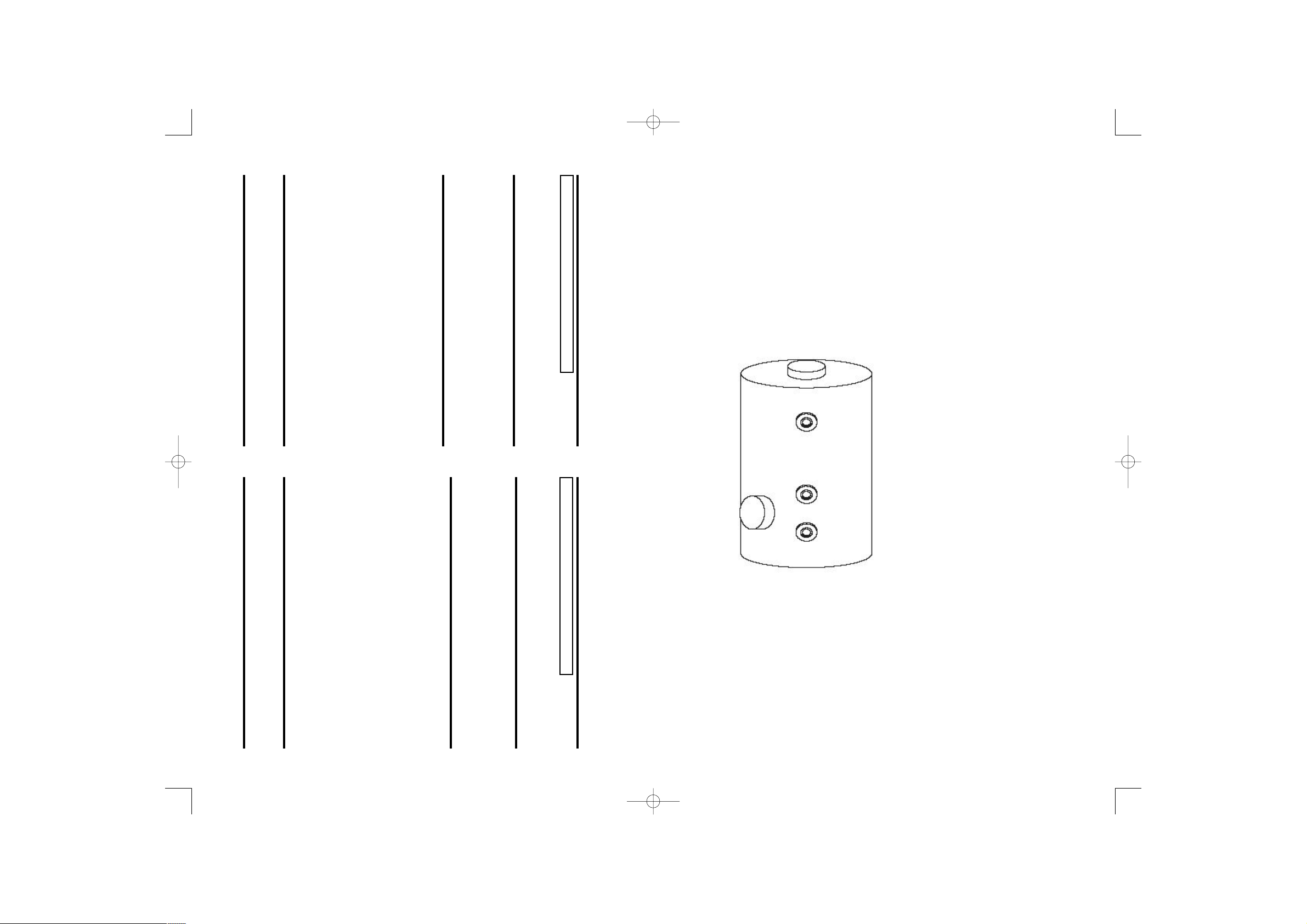
KESTON q-Spa UNVENTED CALORIFIER
Manufacturer Keston Boilers Ltd, 34 West Common Road,Hayes,
Bromley,Kent BR2 7BX UK
Tel:020 8462 0262, Fax:020 8462 4459
E: info@keston.co.uk www.keston.co.uk
SERIAL NUMBER:
Number of heat exchangers 2
Mass Full kg
Weight of store (empty) kg
Dimensions of store (without insulation) 450mm x 1231mm
Max. supply pressure 12 bar
Expansion valve setting 6 bar
Expansion vessel charge 3 bar
Max. working pressure secondary 6.0 bar
Max. working pressure Upper Coil 3.5 bar
Max. working pressure Lower Coil 3.5 bar
Total net fluid content of secondary litres
Fluid content of Upper Coil litres
Fluid content of Lower Coil litres
Secondary volume heated by Upper Coil litres
Area Upper coil sq.m Area Lower Coil sq.m
Secondary volume heated by Lower Coil
Immersion Heater 3kW / 230VAC / 50Hz BS EN 60730-2-1
WARNING TO USER
i. Do not remove or adjust any component part or this unvented
water heater.Contact the installer.
ii. If this unvented water heater develops a fault, such as a flow of
hot water from the discharge pipe, switch the heater off and
contact the installer.
WARNING TO THE INSTALLER
i. This installation is subject to building regulation approval, notify
the Local Authority of intention to install.
ii. Use only manufacturers replacement parts.
Completion Date
THIS UNIT WAS INSTALLED BY:
ADDRESS:
TEL:
KESTON q-Spa UNVENTED CALORIFIER
Manufacturer Keston Boilers Ltd, 34 West Common Road,Hayes,
Bromley,Kent BR2 7BX UK
Tel:020 8462 0262, Fax:020 8462 4459
E: info@keston.co.uk www.keston.co.uk
SERIAL NUMBER:
Storage Capacity litres
Mass Full kg
Max. Supply Pressure 12 bar
Expansion Vessel Charge 3 bar
Expansion Valve Setting 6 bar
Max. Primary Pressure 3.5 bar
Operating Pressure 3 bar
Immersion Heater 3kW / 230VAC / 50Hz BS EN 60730-2-1
WARNING TO USER
i. Do not remove or adjust any component part or this unvented
water heater.Contact the installer.
ii. If this unvented water heater develops a fault, such as a flow of
hot water from the discharge pipe, switch the heater off and
contact the installer.
WARNING TO THE INSTALLER
i. This installation is subject to building regulation approval, notify
the Local Authority of intention to install.
ii. Use only manufacturers replacement parts.
Completion Date
THIS UNIT WAS INSTALLED BY:
ADDRESS:
TEL:
Keston Manual Phase 5 1/5/07 08:41 Page 1
Page 2
INTRODUCTION
READ CAREFULLY BEFORE INSTALLATION
INCORRECT INSTALLATION MAY INVALIDATE GUARANTEE
CONTENTS PAGE
1. Component Check List 3
2. Handling and Storage 4
3. Location and Cylinder Mounting 4
4. Warnings 4
5. Markings and Specification 5
6. Connection Layout and Recommendations for 7
Pipework and Discharge Lines
7. Flushing and Commissioning 9
8. Electrical Specification and Wiring 10
9. Secondary Circulation 10
10. Scale Advice and Maintenance 11
11. Trouble Shooting and Maintenance 11
12. Spares 12
13. Safety & Relevant British Standards 12
14. Tank Data Plate 12
Note to Installer: Please leave Installation manual with Householder after installation
The Keston q-Spa is a range of Duplex stainless steel un-vented water heaters with ultra high
performance coils for indirect heating. The use of stainless steel for both coil and tank ensures long life
and high strength ensuring high pressure performance. The ultra high efficiency coils give rapid reheat
and high volume hot water delivery.
The units are supplied with manifold type pressure regulating/expansion relief valves preset to 3bar and
with integral strainer. However, the manifold can be separated to two sections should you wish to install
the pressure regulating valve at a remote location. An expansion vessel is also supplied for connection to
the cold supply. Use of an external expansion vessel allows the entire volume of the tank to be used for
water storage.
The units are also fitted with a 3kW electric immersion heater as standby heating and adjustable
thermostat with overheat shut down to control the supply of indirect heat to the unit.
Operating Data:
Performance Data:
NB: Above figures assume constant primary coil flow of 82C and sufficient heat input to fully utilise
the coil output. q-SpaTwin figures assume both coils used concurrently with sufficient boiler power
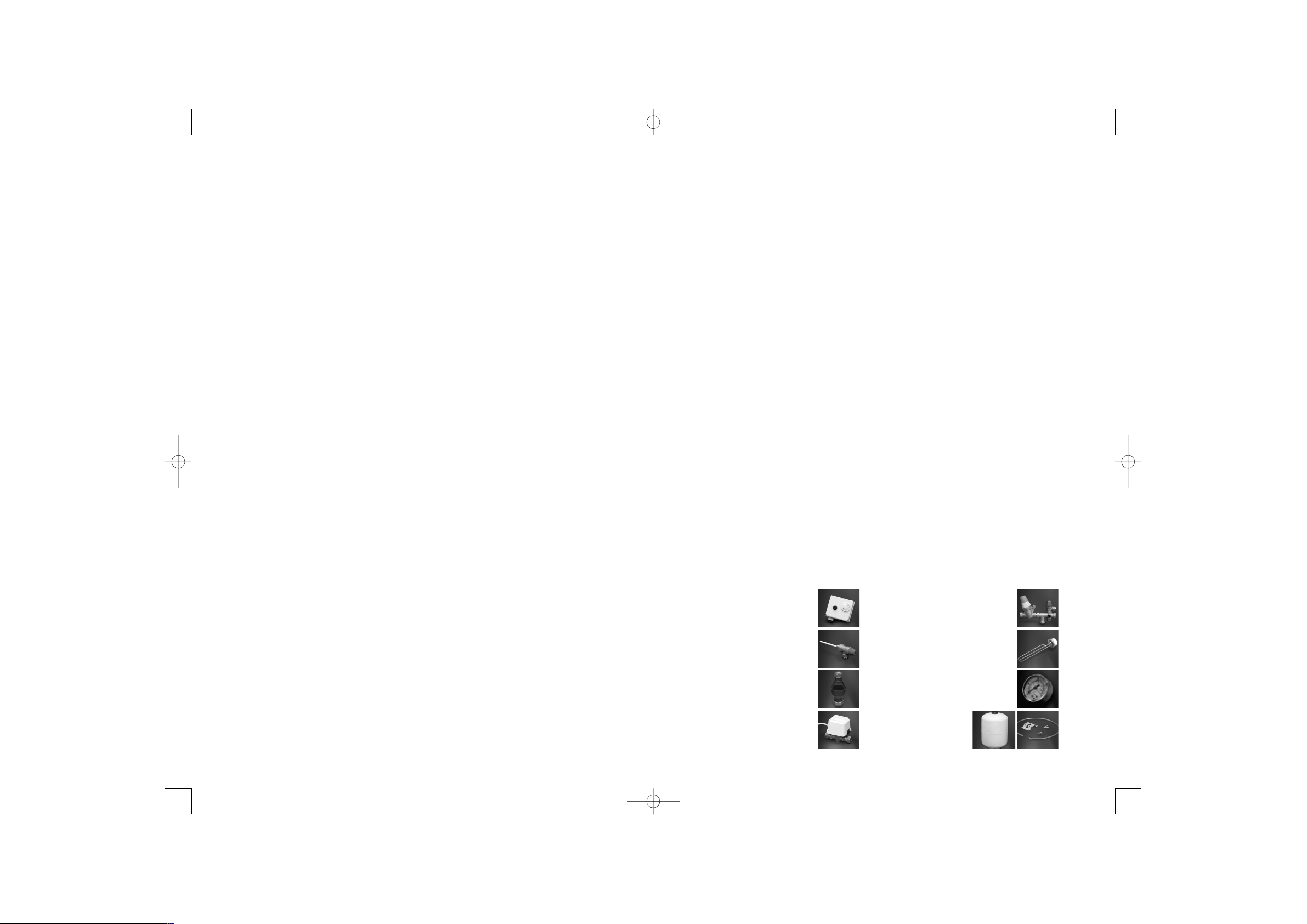
1. Component Check-List
The following items accompany your q-Spa Unvented Storage Cylinder.
Combined control and overheat
thermostat with manual cut-out
switch, variable thermostat
(30 -70C) and sensor.
90C/7 bar Temperature and
Pressure (T&P) relief valve
Discharge tundish
2-Port Motorised Valve
Combined strainer/pressure
reduction valve, 3.0 bar, with stop
tap, check valve, expansion relief valve
3kW /230 VAC electric element with safety
cut-out switch and variable thermostat -
1.75” BSP head
Diagnostic gauge
Expansion vessel, hose and
wall mounting kit
3
Maximum Water Supply Pressure to pressure regulating valve
Operating Pressure of unit
Expansion Vessel Charge Pressure
Expansion Relief Valve Setting
Maximum Primary Working Pressure
Opening Temperature of T&P Valve
Opening Pressure of T&P Valve
12.0 bar
3.0 bar
3.0 bar
6.0 bar
3.5 bar
90C
7 bar
Model q-Spa q-Spa q-Spa q-Spa q-Spa Twin q-Spa Twin
120 150 210 300 210 300
Re-heat 15C 60C (approx) 23mins 25mins 35mins 44mins 18mins 22mins
Re-heat after 70% draw-off 17mins 17mins 22 mins 28 mins 11 mins 14 mins
(approx)
Keston Manual Phase 5 1/5/07 08:42 Page 3
Page 3

2. Handling & Storage
- Do not lift via valves or element bosses on unit
- Expansion vessels must not be dented.
- Store unit away from excess heat or frost
- Always transport cylinders in the vertical position
3. Location and Cylinder Mounting
- Site the unit as close as possible to main points of usage. Outlets above the q-Spa
unit will reduce the outlet pressure by 0.1 bar for every 1m of height difference.
- Avoid locating the unit where freezing temperatures may be experienced. All
expose pipework should be insulated.
- Ensure unrestricted access to plumbing connections and top of expansion vessel
- Allow sufficient clearance for removal of immersion heater and valves.
- In floor standing the unit place the unit on a load bearing surface sufficient for the
weight of the unit when full of water.
- The unit must be installed and transported vertically unless otherwise indicated on
packaging
- The connection for the expansion relief valve and the temperature pressure relief
valve must not be used for any other purpose
- Valves can be mounted in any orientation provided discharge downpipes can be run
to drain in accordance with instructions (see Tundish).The discharge pipework
should have a minimum fall of 1:200 from the unit.
- A drainage safe tray should be placed under the cylinder to facilitate servicing
4. Warnings
- Boilers without thermostatic control, such as and steam heating plant should not be
used with this unit unless appropriate additional safety controls are installed. Solid
fuel boiler must not be used with any unvented unit.
- Under no circumstances must the unit be filled or operated without the factory
fitted T&P relief valve.
- Do not fit a stop or check valve between the inlet safety group and the cylinder
- Do not apply heat to any component or any welding to cylinder or pipe connections.
- All electrical wiring should be carried out by a registered electrical contractor and
must conform to IEE Wiring Regulations.
- If a replacement immersion heater is required at any time, do not fit an immersion
heater(s) without thermal cut-out(s).
- Ensure unit is flushed for 3 minutes via hot tap before switching on.
- Do not use excessive plumbers paste or flux, which may damage the controls.
- Do not switch on power until the unit is full of water. Do not open electric elements
unless power is switched off.
- Position discharge tundish away from any electrical components.
Markings and Specification
Single Coil q-Spa
4
5
Hot Outlet
Secondary Return Circuit
(210, 250 & 300 L sizes
Expansion
Vessel
with Wall
Bracket
Flexible
Hose
Bronze
Pump
Boiler
Flow
Boiler
Return
Immersion
Heater
Non
Return
Valve
Non
Return
Valve
Expansion
Relief
Valve
Pressure
Reducing
Valve
Isolating
Valve
Temperature
& Pressure
Relief Valve
Tundish
2 Port
Valve
Dual
Stat
Cold
Main
Cold Inlet
via Drain
22mm Hot Drawoff
1/2”F PTRV Boss
1/2”F Stat Bosses
F
E
A
B
C
D
22mm
Secondary return
(not always fitted,
see table)
Second
Immersion
Heater
(not always fitted,
see table)
22mm Cold feed with
dip pipe to deflector
in bottom of cylinder
MODEL CAPACITY WEIGHT DIMENSIONS (in mm) IMM
(Litres) Empty Full Height Dia A B C D E F (kW )
(kg) (kg)
q-Spa 120 120 35 155 906 550 290 330 390 345 N/F N/F 3
q-Spa 150 150 40 190 1093 550 330 370 465 385 N/F N/F 3
q-Spa 210 210 50 260 1469 550 365 405 465 465 N/F 1150 3
q-Spa 300 300 60 360 2032 550 365 405 465 660 1100 1600 6
Double Coil q-SpaTwin
22mm Hot Drawoff
Secondary return
(not always fitted)
1/2”F PTRV Boss
F
E
H
G
A
B
C
D
MODEL CAPACITY WEIGHT DIMENSIONS (in mm) IMM
(Litres) Empty Full Height Dia A B C D E F G H (kW)
(kg) (kg)
q-Spa Twin 210 210 55 265 1469 550 365 420 779 834 1150 1268 465 830 3
q-Spa Twin 300 300 60 365 2032 550 365 420 979 1034 1600 1832 465 1030 3
1/2”F Stat Bosses
22mm Cold feed
with dip pipe to
deflector in bottom
of cylinder
22mm
Primary Coil
Connections
Balanced
Cold Connection
Keston Manual Phase 5 1/5/07 08:42 Page 5
HOT OUTLET
SECONDARY RETURN CIRCUIT
( 210, 250 & 300 L SIZES )
NON
BRONZE
RETURN
PUMP
VALVE
2 PORT
VALVE
BOILER
FLOW
BOILER
RETURN
IMMERSION
HEATER
TEMPERATURE
& PRESSURE
RELIEF VALVE
DUAL
STAT
TUNDISH
RETURN
VALVE
COLD
INLET VIA
DRAIN
EXPANSION
RELIEF
VALVE
NON
PRESSURE
REDUCING
VALVE
FLEXIBLE
HOSE
EXPANSION
VESSEL
WITH WALL
BRACKET
ISOLATING
VALVE
BALANCED
COLD
CONNECTION
COLD
MAIN
Page 4

6. Connection Layout & Recommendations
The performance of any unvented mains fed cylinder is always limited by the supply of mains water to
the unit. A high static mains pressure is not a guarantee of adequate supply. The static mains supply
pressure should be measured as well as the size of the supply pipe. Unvented mains fed cylinders
should not be used where the water supplies have inadequate pressure, flow rate or where the supply
may be intermittent.
1. For cylinder sizes up to 300 litres a suggested supply pressure of 1 bar or more is desirable.
2. For cylinders of 200 litres or below with water pressure below 1.5 bar use 22mm supply and
distribution pipework.
3. Use 22mm pipe distribution up to the first branch connection
4. For 300 litres and over use 28mm or larger pipework. If long pipe runs are required extra
expansion vessel capacity may be necessary.
5. All hot pipework should be insulated.
6. Use the balanced cold take-off connection of the pressure reduction valve to ensure
satisfactory shower performance. However,it should be noted that this will reduce the total
available regulated flow available from the tank.
7. Do not vent the primary circuit from the boiler to the water heater system.
8. Better performance will be obtained by using 22mm pipe, limiting the number of elbows and
fittings and using swept bends.
9. Follow connection layout on page 3. Connect valves with flow in arrow direction marked on
valve bodies.
10. For indirect cylinders the control thermostat and overheat thermostat must be wired to the
motorized valve supplied, or some other suitable device to shut off the flow to the coil that is
approved by a member of EOTA or by a body with NACCB accreditation.
11. The high efficiency coil of the q-Spa tanks offer a higher resistance to boiler water flow than
other lower efficiency traditional cylinders. Consideration should therefore be given to
additional pump capacity or a coil flow/return bypass arrangement. Such a by-pass may then
be adjusted to balance cylinder and boiler flow accordingly. Refer to the cylinder coil pressure
drop curves below for pump selection.
12. For twin coil models the boiler should be connected to the upper coil. The lower coil should
be used for the additional heat source, such as solar thermal or heat pump.
6
7
How to drain the System
1. Switch off the electrical power to the immersion heater(s) and shut down the boiler. Close the stop
cock valve.
2. Open a hot water tap in order to reduce pressure in the cylinder. Leave the hot water tap open.
3. Connect a hose to the draining tap ensuring it reaches a level below the unit (this will ensure a siphon
is established to drain the maximum amount of water)
CAUTION WATER DRAINED OFF MAY BE VERY HOT!
Discharge Pipework and Tundish
- Tundish must be visible
- Discharge pipe must be to fixed grating and not located to cause possible discharge injury to persons.
Typic
al Discharge Pipe Arrangement
Table 1: Sizing of copper discharge pipe D2 for common temperature relief valve outlet sizes.
Valve Min size Min size of Maximum resistance allowed Resistance created
Outlet of discharge discharge pipe as a length of straight pipe by each elbow or
Size pipe D1 D2 from tundish (i.e. no elbows or bends) bend
G1/2 15mm 22mm up to 9m 0.8m
28mm up to 18m 1.0m
35mm up to 27m 1.4m
G3/4 22mm 28mm up to 9m 1.0m
35mm up to 18m 1.4m
42mm up to 27m 1.7m
G1 28mm 35mm up to 9m 1.4m
42mm up to 18m 1.7m
54mm up to 27m 2.3m
Worked example:
The example below is for a G1/2 temperature relief valve with a discharge pipe (D2) having 4 no. elbows
and length of 7m from the tundish to the point of discharge.
From Table 1: Maximum resistance allowed for a straight length of 22mm copper discharge pipe (D2) from
a G1/2 temperature relief valve is 9.0m. Subtract the resistance for 4 no. 22mm elbows at 0.8m each =
3.2m
Therefore the maximum permitted length elbows equates to 5.8m is less than the actual length of 7m
therefore calculate the next largest size. Maximum resistance allowed for a straight length of 28mm pipe
(D2) from a G1/2 temperature relief valve equates to 18m. Subtract the resistance for 4 no. 28mm elbows
at 1.0m each = 4m.
Therefore the maximum permitted length equates to 14m.
As the actual length is 7m, a 28mm (D2) copper pipe will be satisfactory.
The tundish should be vertical, located in the same space as the q-Spa tank and fitted as close as possible
and within 500mm of the temperature relief valve.
The discharge pipe D2 from the tundish should terminate in a safe place where there is no risk to persons
in the vicinity of the discharge, be of metal and:
a) be at least one pipe size larger than the nominal outlet size of the safety device unless its total
equivalent hydraulic resistance exceeds that of a straight pipe 9m long i.e. discharge pipes
between 9m and 18m equivalent resistance length should be at least two sizes larger than the
nominal outlet size of the safety device, between 18m and 27m at least 3 sizes larger,and so
on. Bends must be taken into account in calculating the flow resistance. Refer to the worked
example.
An alternative approach for sizing discharge pipes would be to follow BS6700: 1987
Specification for design, installation, testing and maintenance of services supplying water for
domestic use within buildings and their curtilages, Appendix E, section E2 and table 21.
Keston Manual Phase 5 1/5/07 08:42 Page 7
Page 5

b) have a vertical section of pipe at least 300mm long, below the tundish before any elbows or
bends in the pipework
c) be installed with a continuous fall.
d) have discharges visible at both the tundish and the final point of discharge but where this is
not possible or is practically difficult there should be clear visibility at one or other of these
locations. Examples of acceptable discharge arrangements are;
i) ideally below a fixed grating and above the water seal in a trapped gully.
ii) Downward discharges at low level; i.e.up to 100mm above external surfaces such as car
parks, hard standings,grassed area etc. are acceptable providing that where children may play
or otherwise come into contact with discharges a wire cage or similar guard is positioned to
prevent contact, whilst maintaining visibility.
iii) Discharges at high level; e.g.into a metal hopper and metal down pipe with the end of the
discharge clearly visible (tundish visible or not) or onto a roof capable of withstanding high
temperature discharges of water 3m from any plastics guttering system that would collect
such discharges (tundish visible)
iv) Where a single pipe serves a number of discharges, such as in blocks of flats, the number
served should be limited to not more than 6 systems so that and installation discharging can
be traced reasonable easily.The single common discharge pipe should be at least on pipe size
larger than the largest individual discharge pipe D2 to be connected. If unvented hot water
storage systems are installed where discharges from safety devices may not be apparent i.e.
in dwellings occupied by blind, infirm or disabled people, consideration should be given to
the installation of an electronically operated device to warn when discharge takes place.
7. Flushing and Commissioning
- Ensure all pipe connections are tight, including immersion heater(s).
- Check the immersion heater setting is not above 60C and that the live and neutral
connections are correct.
- Open a hot tap farthest from the unit. Open the mains stop cock to fill the unit.
- Flush for three minutes.
- Close off taps and check pipework for leaks.
- Switch on electricity to the immersion heater(s) or switch on the boiler. Refer to boiler
manufacturer s instructions or commissioning.
- Bring the unit to approx 65C. Check that water does not discharge via the Tundish pipework
during heating.
Note: The discharge will consist of scalding water and steam. Asphalt, roofing felt and nonmetallic rainwater goods may
be damaged by such discharges.
8
9
Discharge pipe (D1) from
temperature relief valve to
tundish
Safety device e.g
temperature relief valve
Tundish
600mm
300mm
max
Fixed Grating
Trapped Gully
Discharge pipe (D2) from
tundish with continuous fall
Temperature
Relief Valve
Temperature Relief Valve
Expansion
Relief Valve
Tundish in same
compartment as original
package
500mm
max
300mm
Pipe close to wall
100mm
max
Pipe diameter below
tundish increased by one
size
Expansion
Relief Valve
500C
Inlet pipe
25mm
300mm
Alternative method at
tundish
Must be larger than inlet pipe
Alternative method of
termination at high level
End of discharge pipe; diameter of pipe must
be kept off wall
minimum
- Hand guarantee card to user.
Electrical Specification and Wiring ( Thermostat Control)
- The cylinder control thermostat is mounted at the top of the unit in a housing with cable
entry point.
- The unit houses two thermostats, a control thermostat and an overheat thermostat.
Operation of either thermostat must cease the supply of heat to the cylinder.
- Remove the thermostat housing cover.Wire the two thermostats inside in series to the hot
water control valve as shown below. Electrical Specification and Wiring (Thermostat Control)
for additional heat source refer to the suppliers manual. However, the manual reset limit ther
mostat should be used to isolate any further supply of heat to the q-Spa.
9. Secondary Circulation
- A pump is required together with a non-return valve.
- The pump should be fitted with isolating valves on either side and sited to minimise air
accumulation away from the high point of the circuit. An air bleed valve may be located at
the high point.
8. Electrical Specification & Wiring (Immersion Heater)
- Element terminals are marked N(Neutral) and L(Live)
- Ensure earth connection of 3 wire supply is connected to earth.
- Recommended supply for 3kW element is 2.5mm cable to BS6141
- A 16 Amp timer is recommended for 3kW elements
- The unit is not fitted with a fuse.
- All heating elements operate on a 230 VAC 50Hz mains supply.Do not fit immersion
heater(s) without thermal cut-out(s).
FUSE RATING:
The fuse rating for two 3kW immersion heaters wired separately from the main fuseboard should be 15
Amps.
Immersion
Heater Wiring
Connect Earth
Connect Neutral
Cut out
Connect Live to
thermostat
Heat resisting cable
from Double Pole
isolating switch
Electrical Wiring
Drawing
Cylinder Thermostat
Brown
Blue
Green/Yellow
Grey
Orange
Motorised Valve
To Boiler
From Timeclock
DHW Output
Keston Manual Phase 5 1/5/07 08:42 Page 9
Page 6

- The return pipe should be fitted to the secondary return/drain off tapping near the base of
the cylinder.
- A drain off cock (not supplied) should be fitted in-line in the secondary return near the
connection to the cylinder to facilitate drainage of the cylinder for maintenance purposes.
- A non-return valve (not supplied) must be fitted to prevent backflow.
- Calculate the flow rate and pump size by determining the total heat loss in flow and return
in watts.
- Consideration should be given to the fitting of an additional vessel where excessively large
secondary loop circuits are used.
Required flow rate = Total Watts litres/second
4186 x 1000 x T
where T = temperature difference between flow and return (normally the desirable drop is 5C and the
hot water temperature should be 60C).
10. Scale Advice and Maintenance
- In areas of hard water high storage temperatures (above 50C) will result in scale deposition
- It is advisable to set the thermostat to the required level and fit a water softener or scale
inhibitor (capable of the required circuit flowrate) in the cold supply line.
Maintenance
- The valve easing gear on the pressure and temperature relief valve must be operated at
least once every 6 months.
- The charge pressure of the expansion vessel should be checked annually with a pressure
gauge at the top (and with a hot tap open and the cold supply turned off ).Recharge with
clean dry air to 3.5 bar.
- Clean the pressure reducing valve filter every 2 years or of flow from water heater begins to
deteriorate.
11. Trouble Shooting & Fault Guide
WARNINGS
If hot water discharges at tundish do not turn off supply main, Switch off power to electric
elements and shut down heating boiler (indirect models).
The cause of this could be a failure of the safety controls and you should immediately contact
your installer or our service operator.
SYMPTOMS POSSIBLE CAUSES ACTION
1. No or low flow - Poor mains pressure - Check that all arrows on valves are in water flow direction.
- Restricted pipework - Use larger diameter pipework
- Mains stopcock - Operate stopcock or replace
- Sticking jumper in stop - Replace stop cock
- Blocked filter - Clean filter
2. Discharging cold - Loss of expansion vessel - Check and recharge vessel relief valve (with hot tap open)
- Defective pressure - Replace pressure valve reducing valve
- Blocked or defective - Operate expansion valve expansion relief valve
mechanism to clear or replace
- Crossflow from cold supply - Check mixer taps and fit check through mixer top or other
valve on hot outlet from heater fittings.
3. Water is cold - Boiler not switched on - CARRY OUT PROCEDURE BELOW
(indirect)
- Air locked primary flow
- Thermostat settings incorrect
- Cut out switch need reset
Warnings (Electric Models)
Always isolate the electrical supply before opening heating elements.
Confirm that power supply is reaching the elements.
If thermal cut-out switches have operated press in the red button. If this fails to heat the
cylinder the element has failed and should be replaced. Fit new element and reset thermal cut-out.
With power to the element and the cut-out reset, check the voltage on thermal cut-out output.
If this is incorrect replace cut-out switch.
10
11
12. Spares
13. Safety & Relevant British Standards
Installation of this tank as an unvented hot water system falls within the scope of the Building
Regulations 1995 (Part G). These require that installation of an unvented system shall be noti
fied to the local authority Building Control Department; also that the work must be carried
out by a competent person as defined in the Approved Document G3.
The Electricity at Work Regulations 1989.
The manufacturers notes must NOT be taken, in any way,as overriding statutory obligations.
ITEM DESCRIPTION MODEL SPECIFICATION
1/2 inch Temperature and
Pressure Relief Valve
KSI.120.04.00.1 1/2 inch male inlet, 15mm comp.
outlet, 90C,7 bar
3/4 inch pressure reduction valve,
expansion relief manifold
KSI.125.06.00.0 2 2mm comp inlet, 22mm comp
outlet, 3 bar supply,6 bar relief.
12 litre Expansion Vessel
(120, 150 litre sizes)
KSI.200.01.00.1 3/4 inch male inlet. 3 bar
18 litre Expansion Vessel
(210 litre size)
KSI.300.03.00.0 3/4 inch male inlet. 3 bar
24 litre Expansion Vessel
(300 litre size)
KSI.400.01.00.1 3/4 inch male inlet. 3 bar
Immersion Heater KSI.125.02.00.1 3kW.2.25 inch male. 80C cut-out
1.75inch boss
Control Thermostat KSI.125.03.02.0 Adjustable 30 to 70C
Overheat Thermostat KSI.125.03.01.0 80C Cut-Out Manual Reset
Motorized Valve 22mm KSI.125.07.00.2 22mm 2-port valve
Tundish KSI.125.10.00.0 15mm/22mm Compression
Diagnostic Gauge
Expansion Vessel Hose
Keston Manual Phase 5 1/5/07 08:42 Page 11
 Loading...