

Keston K60, K80, K50 Installation Manual
WD50/2/1997 The Keston 50, 60 & 80 Condensing Boilers
Fan Powered High Efficiency Condensing Gas Boiler
Installation And Servicing Instructions
Keston 50 - GC No 41 930 01
Keston 60 - GC No 41 930 02
Keston 80 - GC No 41 930 03
PI No. : 87AQ306
These instructions must be left either with the user or next to
the household gas meter.
34 West Common Road
Hayes, Bromley, Kent BR2 7BX
Tel. (44)0208 462 0262 Fax. (44)0208 462 4459
0087

WD50/2/1997 The Keston 50, 60 & 80 Condensing Boilers
CONTENTS
Section Description
1 GENERAL INSTRUCTION
1.1 Description
1.2 Boiler Schematic
1.3 Related Documents
1.4 Performance Data
1.5 General Data
2 BOILER LOCATION
2.1 Dimensions & Minimum Clearances
2.2 Service Connections
2.3 Position
2.4 Electrical
2.5 Boiler Size Selection
2.6 Gas Supply
2.7 Water Systems
2.8 Flue System
2.9 Air Supply
2.10 Compartment Installation
2.11 Condensate Drainage
2.12 Radiant Floor Heating
2.13 Low Water Volume Boiler vs. Cast Iron Boiler
2.14 Determine Radiation Needed Room-By-Room
3 INSTALLATION OF THE BOILER
3.1 Wall Mounting Bracket
3.2 Mounting The Boiler
3.3 Assembly Practice
3.4 Installing Flue And Air Pipes
3.5 Condensate Drainage
3.6 Water System
3.7 Gas Supply
3.8 Electrical Supply
3.9 Exchanging A Boiler
4 COMMISSIONING OF THE BOILER
4.1 Initial Flushing
4.2 Gas Supply
4.3 Electrical Installation
4.4 LP Gas Conversion
4.5 Initial Firing
4.6 Hot Flushing
4.7 Checking The Gas Pressure
Page : i

WD50/2/1997 The Keston 50, 60 & 80 Condensing Boilers
4.8 Timing The Gas Meter
4.9 Handing Over To The User
5 FAULT FINDING
5.1 Electrical Control Sequence
5.2 Fault Finding Flow Chart
5.3 Continuity Checking
5.4 Functional Flow Wiring Diagram
5.5 Electrical Wiring Diagram
5.6 Illustrated Wiring Diagram
5.7 Exploded Assembly Diagrams
6 SERVICING
6.1 Pre Service Checks
6.2 Recommended Routine Service
7 REPLACEMENT OF PARTS
7.1 General
7.2 Precautions
7.3 Access
7.4 Electrical
7.5 Gas Orifice
7.6 Spark Ignition/Flame Detection Electrode
7.7 Burner Head & Burner
7.8 Heat Exchanger
7.9 Air Filter
7.10 Condensate Trap
7.11 Pressure Gauge
7.12 Sight Glass
7.13 HT Ignition Lead
7.14 Air Vent
7.15 Air Orifice
8 SPARE PARTS LISTINGS
Page : ii

WD50/2/1997 Chapter 1 : General Instruction The Keston 50, 60 & 80 Condensing Boiler
1. GENERAL INSTRUCTION
1.1 DESCRIPTION
The Keston Condensing Boiler is unique in its concept and design. While the application
for which the boiler was designed is the same as those which other boilers are us ed the
Keston boiler has the added advantage of very high efficiency, and small diameter plastic
flue which can be extended to 10 metres horizontally or vertically.
The Keston uses a high power combustion blower to deliver a pre-mix of gas and air to a
downward firing burner in a high efficiency, single pass heat exchanger.
o
Normally the combustion temperature of the air gas mixture is around 1800
Keston achieves combustion at an am azing 1000
o
C thereby reducing the NOx emissions
down to an incredible less than 5 p.p.m.
The flue system is room sealed and fan powered. The ignition is direct spark and fully
automatic. The boiler housing is not waterproof. The boiler should be installed in a
position where it will always be dry. A small air intake point is incorporated within the
appliance cabinet to ensure that the interior of the cabinet is maintained under a slight
negative pressure. This is a safety feature to ensure no products may leak out of the
cabinet into the installation space.
C but the
s
The boiler is suitable f or connection to open vented or sealed s ystems. T he system mus t
be pumped central heating or pumped central heating with combined indirect domestic hot
water. Gravity circuits must not be used.
The boiler has a primary heat exchanger which, through its combustion chamber and
corrugated coil, transf ers the heat produced in the hot gas es of combus tion process into
the circulating water. Head characteristics of the boiler coil must be taken into
consideration when calculating the pump size.
The Keston boiler is not a high water content boiler and does not contain the metal mass ,
or water volume, of a cast iron or steel boiler. This boiler is of low mass and low water
content and therefore responds fast er when there is a call for heat. Th is f eatur e requir es a
higher water pumping rate thr ough the boiler otherwise localised boiling will occur within
the boiler.
Allow a pressure drop through the boiler of 3.2 ft head and a water flow of 4.2 gallons (19
litres) per minute f or the Keston 50, 4.3 f t head and 5 gallons (23 litres) per m inute for the
Keston 60 and 9 ft head and 6.7 gallons (30.5 litres) per minute for the Keston 80.
The boiler selected m ust be sized relative to the total c alculated heat loss of the building.
The boiler rated output should not be greater than the total required to make up the
calculated heat loss plus the heat required to provide domestic hot water. If there are
special conditions such as excessive domestic hot water usage consult the manufacturer.
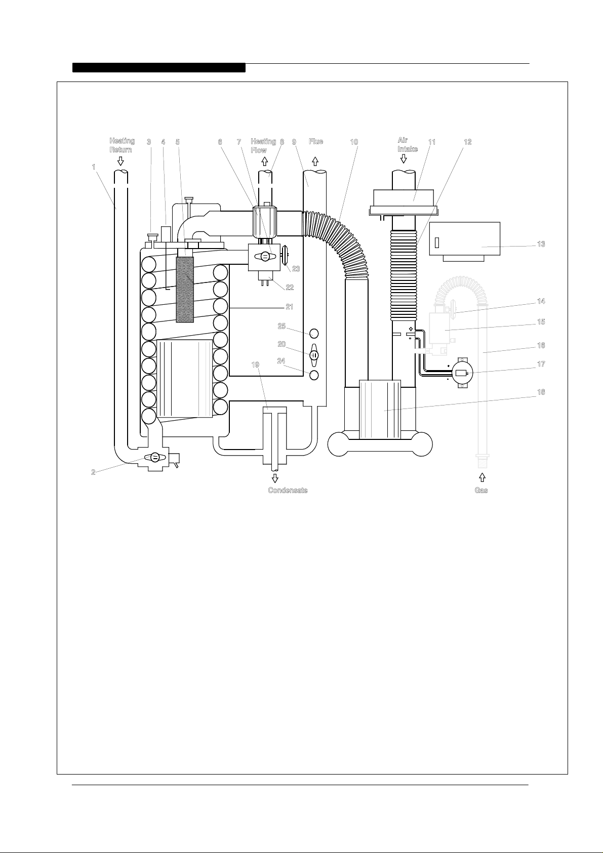
1.2 BOILER SCHEMATIC
Air is drawn into the boiler through a 40mm ( BS5255) m uPVC pipe. T he air f low is proved
by a differential pressure across the air control orifice.
Gas is mixed with com bustion air at the inlet to the fan. The gas flow is regulated by an
orifice located in the housing downstream of the gas valve.
Installation & Servicing Instructions
Page : 1
WD50/2/1997 Chapter 1 : General Instruction The Keston 50, 60 & 80 Condensing Boiler
Figure 1.2 Boiler Schematic
s
LEGEND
1 Heating Return
2 Water Return Thermo stat
3 Downstr eam Pr essture Test Nipple
4 Flame Ignition/Sensing Probe
5 Burner
6 Automatic Air Vent
7 High Limit Thermostat
8 Heating Flow
9 Flue Exhaust
10 Air/Gas Flexible Connector
11 Air Filter
12 Air Inlet Flexible Connector
Installation & Servicing Instructions
13 Ignition Control Box
14 Gas Low Pressure Switch
15 Gas Multifunctional Control
16 Gas Inlet Flexible Connector
17 Air Pressure Switch
18 Combustion Blower
19 Condensate Trtap
20 Flue Overheat Thermostat
21 Heat Exchanger
22 Flow Overheat Thermostat
23 Water Low Pressure Switch
24 Combustion Test Point
Page : 2

WD50/2/1997 Chapter 1 : General Instruction The Keston 50, 60 & 80 Condensing Boiler
The gas and air are thoroughly mixed in the blower and f ed into the burner located at the
top end of the heat exchanger module. The gas and air mixture is ignited by a direct spark
ignition control system and burns with a blue flame j ust off the surface of the burner. As
the hot products of com bustion pass downwards, they are cooled, exchanging heat with
the circulating water which enters the heat exchanger coil at the bottom of the heat
exchanger.
When the return water temperature is below 54oC, part of the water vapour in the
combustion products will condense ins ide the heat exchanger, thus increasing the boiler
efficiency. This condensate falls to the bottom of the heat exc hanger where it is s eparated
from the flue gases and exits from the boiler through the condensate drain. Any
condensate formed in the flue runs back down the flueway and is drained at the base of
the flue connection to the heat exchanger.
The condensate is very slightly acidic (about the same acidity as vinegar) and should be
piped in a plastic pipe. It is not harmful to the waste disposal system and may be disposed
of as normal waste water.
The flue gases are piped in a 40m m m uPVC pipe to the outside. The temper ature of the
flue gases are usually less than
10oC above the temperature of the retur n water. The flue
pipe should be terminated outside the building from where they cannot re-enter the
building or any other adjacent building or cause a nuisance by pluming.
s
The heating level may be controlled by room thermo stats, hot water cylinder thermostats
and programmer time clocks.
1.3 RELATED DOCUMENTS
The Keston Condensing Boiler must be ins talled in accordance with the current issue of
the Gas Safety ( Installation and Use) Regulations, current IEE W iring Regulations, Safety
document no. 635 - The Electricity At Work Regulations 1989, Building Regulations,
Building Standards (Scotland) Consolidation, and the Bye Laws of the local Water
Undertaking.
In addition, due account must be taken to the following Codes Of Practice:
BS 6891 : Gas Supplies
BS 6798 : Installation Central Heating Boilers
BS 5449 : Installation Pumped Central Heating
BS 5546 : Installation Domestic Hot Water
BS 5440.1 : Flues
BS 5440.2 : Air Supply
BS 5482.1 : Domestic Propane & Butane Burning Installations
BS 7074.1 : Expansion Vessels
BS 7593 : Treatment of Water in Hot Water Central Heating
BS 7671 : Requirements for Electrical Installations. IEE Wiring
Systems
Regulations 16th Edition.
For Timber Framed Buildings, British Gas Publications DM2. Also British Gas
Publications 'Guidance Notes For The Installation Of Domestic G as Condensing
Boilers' and 'Specification For Domestic Wet Central Heating Systems'.
Installation & Servicing Instructions
Page : 3
WD50/2/1997 Chapter 1 : General Instruction The Keston 50, 60 & 80 Condensing Boiler
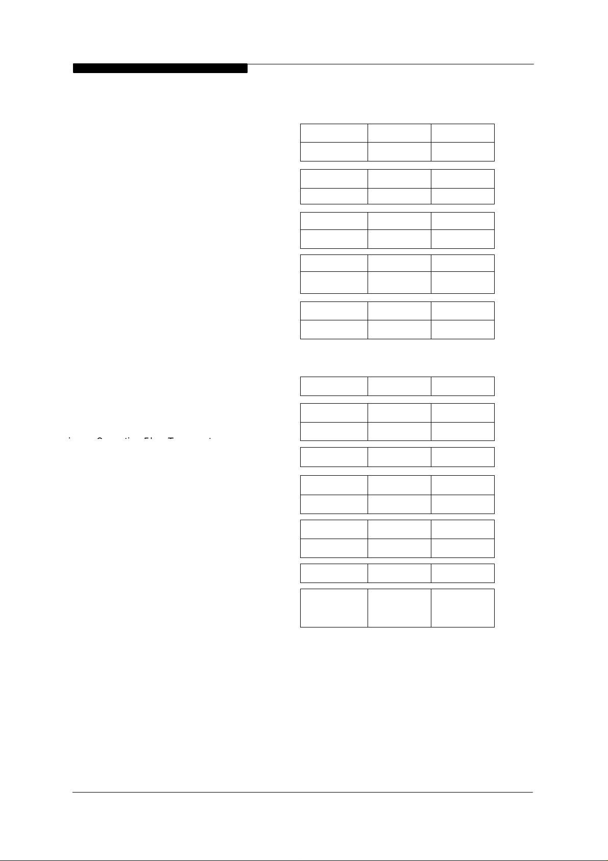
1.4 PERFORMANCE DATA
s
o
C Flow 60oC Return
o
C Flow 40oC Return
(FACTORY PRESET)
(CV of Gas - 38.7 MJ/m3)
(1038 Btu/Ft
3
)
Keston 50 Keston 60 Keston 80
27.119.916.6KWBoiler Input
92,50068,30056,500Btu/h
23.5 17.514.7KWBoiler Output To Water
80,00060,00050,000Btu/h80
2619.215.8KWBoiler Output To Water
88,80065,00054,000Btu/h60
1096mbarBurner Setting Pressure (Hot)
3.943.542.36in w.g.
0.70.510.43L/SGas Consumption After 10 mins
3
/HrRunning
o
CMaximum Operating Flow
89.1165.854.43Ft
80.0080.0080.00
30.5030.5030.50MMaximum Head (Open Systems)
Differential
Ft
o
100.0100.0100.0Ft
2.702.702.70BarMaximum Pressure (Sealed Systems)
2.5MMinimum Head (Open Systems)
2.5
8.08.0
2.5
8.0
20.020.020.0mbarInlet Gas Pressure
8.08.08.0in. w g
3.432.712.38mmGas Orifice Size
CRecommended Temperature
10 to 1510 to 1510 to 15
Installation & Servicing Instructions
Page : 4
WD50/2/1997 Chapter 1 : General Instruction The Keston 50, 60 & 80 Condensing Boiler
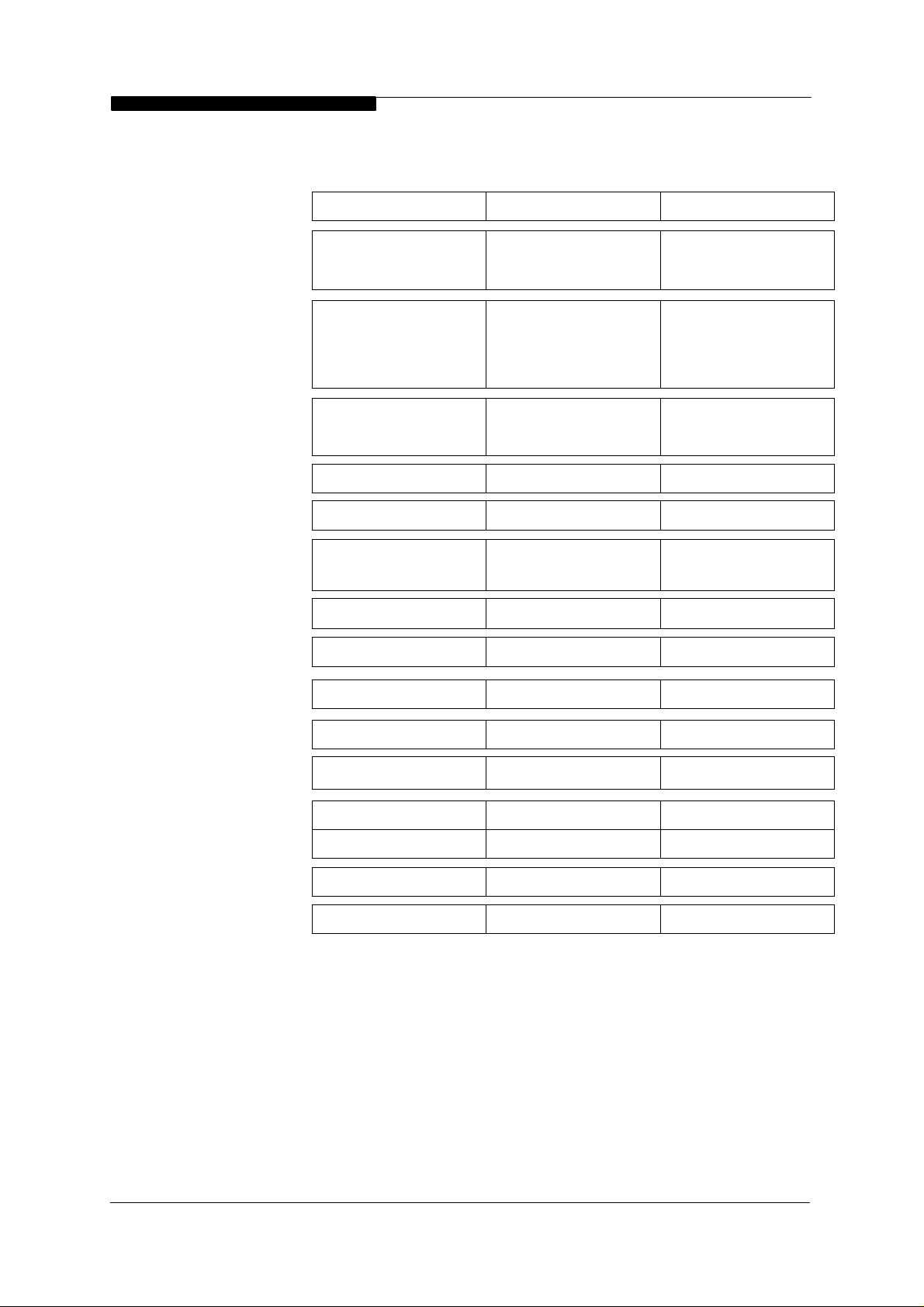
1.5 GENERAL DATA
s
Direct Spark
Gas Supply
Connection
Keston 50 Keston 60 Keston 80
Electronics
RAM
0.5 inch BSPT Male
(15mm to gas cock)
28 mm
CopperFlow Connection
0.5 inch BSPT Male
(15mm to gas cock)
Keston PremixKeston PremixKeston PremixMain Burner
White RogersWhite RogersWhite Rogers Gas Control
36E Series36E Series36E Series
KestonKestonKestonCombustion Fan
Type LPB 102 220/240Type LPB 102 220/240Type LPB 102 220/240
0.18 KW 2900 RPM0.18 KW 2900 RPM0.18 KW 2900 RPM
RAM ElectronicsRAM Electronics
Full Sequence ControlFull Sequence ControlFull Sequence ControlIgnition
Tridelta FS 6717 - 1428Tridelta FS 6717 - 1428Tridelta FS 6717 - 1428Air Pressure Switch
Keston FilterKeston Filter Keston FilterFilter
0.5 inch BSPT Male
(15mm to gas cock)
28 mm Copper28 mm Copper
Return Connection
28 mm
Copper
28 mm Copper28 mm Copper
230V 50Hz230V 50 Hz230V 50 Hz Power Supply
175 W140 W140 WPwr Consumption
5 Amps5 Amps5 AmpsExt. Fuse Rating
52 kg (114 lbs)46 kg (101 lbs)46 kg (101 lbs)Weight - Full
50 kg (110 lbs)44 kg (97 lbs)44 kg (97 lbs)Weight - Empty
Rear panel inside caseRear panel inside caseRear panel inside caseData Badge Posn
3.30 litres2.35 litres2.35 litresWater Content
Installation & Servicing Instructions
Page : 5
WD50/2/1997 Chapter 2 - Boiler Connections The Keston 50, 60 & 80 Condensing Boilers
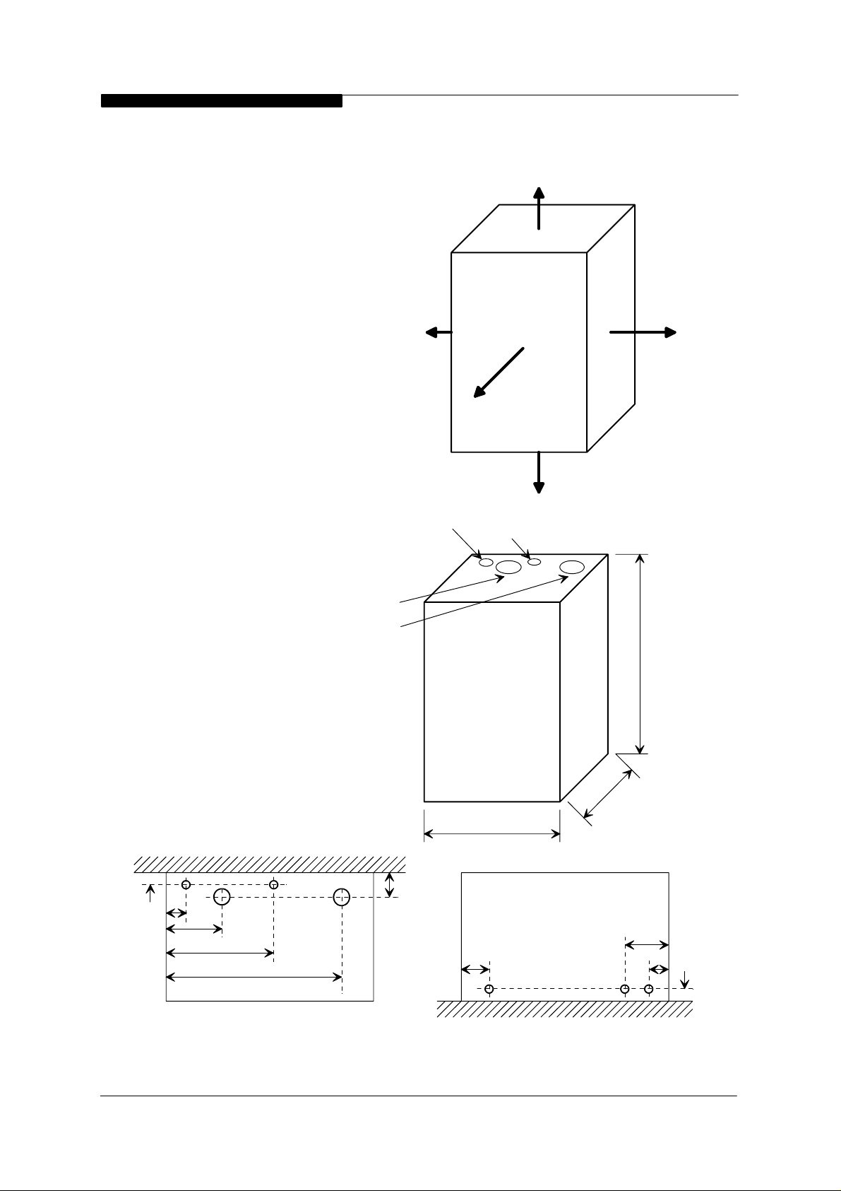
2. BOILER LOCATION
All dimensions in mm.
2.1 DIMENSIONS AND MINIMUM
CLEARANCES
The boiler must be installed in
minimum clearances shown to allow
subsequent servicing, and safe
operation.
254
2.2 SERVICE CONNECTIONS
Gas, water, air and flue pipe,
condensation, and electrical
connections are as shown. Gas : 0.5
inch BSP male. Flow/Return : 28 mm
copper.
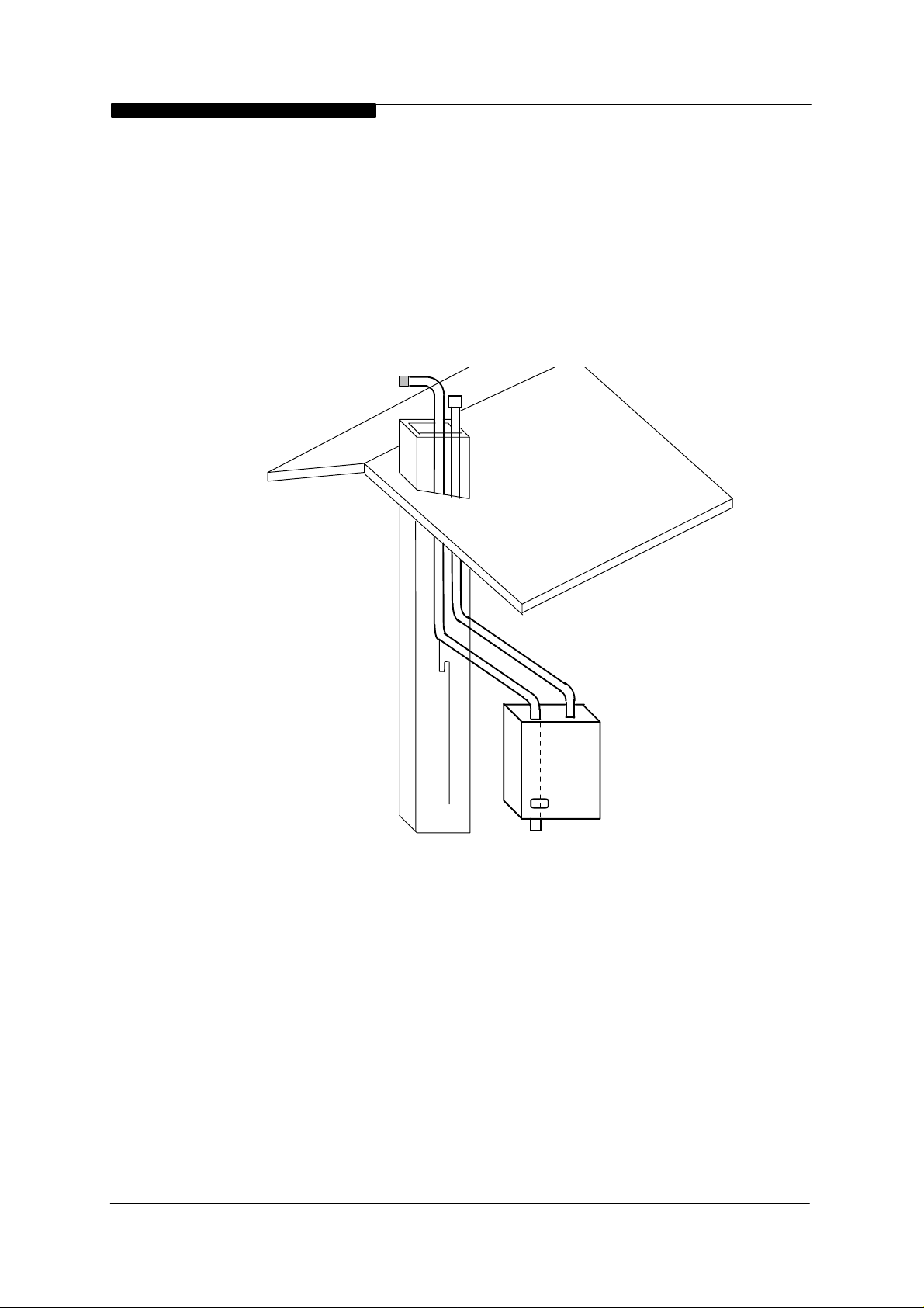
2.3 POSITION
The Keston is not
suitable for external
installation. The boiler
may be installed in any
room or internal space,
although particular
attention is drawn to the
requirements of the
current IEE Wiring
Regulations and, in
Scotland, the electrical
provisions of the Building
Regulations applicable in
Scotland, with respect to
the installation of the
boiler in a room or
internal space containing
a bath or shower.
Air Intake
Flue
1
305
Figur e 2.1.1
Return
127
Flow
Minimum Clearances
All dimensions in mm.
1
890 (Keston 80)
712 (Keston 50 & 60)
Where a room-sealed
appliance is installed in a
27
47
181
237
405
Top View
Installation & Servicing Instructions
Figure 2.1.2
Dimensions
60
Service Connection Locations
Page : 6
500
97
All dimensions are in mm.
Base View
0
0
3
68
30
37
WD50/2/1997 Chapter 2 - Boiler Connections The Keston 50, 60 & 80 Condensing Boilers
room containing a bath or shower, any electrical switch or appliance control, utilising
mains electricity, should be so situated that it cannot be touched by a person using the
bath or shower.
Compartment installation is permitted - such compartments must be constructed in
accordance with BS 6798.
The wall on which the boiler is mounted must be of suitable load bearing capacity and
must be non-combustible.
Important : It is not recommended to install the boiler on a studded wall or similar - it is
possible that the vibration from the fan would be amplified and transmitted to other parts
of the house.
[NB: Refer to
Section 2.8.3]
The Keston can be located virtually anywhere desired provided that all regulations are
met. Because of the boiler's compact size and venting flexibility, the installation is not
limited to a boiler room setting. Before locating the boiler near a living space consider
whether the sounds generated by the boiler will be objectionable. Sound levels from the
boiler are no greater than from any other type of high-efficiency boiler but even minimal
levels may be objectionable if located near a bedroom or in a living area.
2.4 ELECTRICAL
2.4.1 Electrical Connections
Chimneys not used for
venting any other
appliance may be used.
Secure air & flue pipes at
chimney outlet.
Figure 2.3
The boiler must be connected to a 230V ~ 50Hz supply, fused at 5A. All
external controls and wiring must be suitable for mains voltage. Wiring
external tothe boiler must be in accordance with current I.E.E wiring regulations
and local regulations.
Installation & Servicing Instructions
Page : 7

WD50/2/1997 Chapter 2 - Boiler Connections The Keston 50, 60 & 80 Condensing Boilers
The method of connection to the mains electricity supply must facilitate
complete electrical isolation of the boiler complying with the requirements of BS
1363.
The appliance must be connected to the supply via a fused double-pole switch,
having at least 3mm (1/8 inch) contact separation in both poles, serving only the
boiler and the system controls.
The connection point to the mains supply should be readily accessible and
adjacent to the boiler, except for rooms containing a bath or a shower. Refer to
section 2.3 Position.
2.4.2 External Wiring & Controls
1. The boiler is deisgned so that all control wiring is external to the boiler.
Hence, any programmers or room thermostats etc must act by switching
the 230V supply to the boiler.
2. System designs which allow the boiler to fire when there is no pumped
circulation must NOT be used.
3. A programmer may be used with zone valves to give independent
control of central heating and hot water.
2.5 BOILER SIZE SELECTION
The size of the boiler to be used is determined by the total calculated heat loss of the
building. Match the calculated heat loss with the boilers rated output. If a boiler is
installed with an output rating greatly exceeding the total capacity of the distribution
system the efficiency of the boiler will be reduced. If the boiler is to be used to heat
domestic hot water no additional capacity is normally needed for the average residential
installation since there is usually some excess capacity in the boiler as water heating is
an intermittent load.
2.6 GAS SUPPLY
A gas meter should be connected to the service pipe by the local gas supplier or their
contractor. An existing meter should be checked preferably by the gas region to ensure
that the meter is adequate to deal with the rate of gas supply required. Installation pipes
should be fitted in accordance with BS 6891.
Minimum/Maximum Natural Gas Pressure:
Natural gas pressure before the gas valve must be maintained at 20 mbar (8 in w.g)
while the boiler is running.
Gas pressures above or below this level will lead to problems associated with the gas
valve's internal pressure regulator.
Minimum/Maximum L P Gas Pressure:
LPG pressure must be maintained between 31.5 mbar (12.4 in w.g) and 37.6 mbar (14.8
in w.g) while the boiler is running
Gas pressures above or below these levels will lead to problems associated with the gas
valve's internal pressure regulator.
.
Supply pipes to the boiler must not be sized less than the boiler inlet connection (15 mm)
Due consideration must be given to the supply pressure to other gas appliances in the
premises.
Installation & Servicing Instructions
Page : 8

WD50/2/1997 Chapter 2 - Boiler Connections The Keston 50, 60 & 80 Condensing Boilers
A gas cock is supplied loose with the boiler. This cock should be fitted in the gas line to
the boiler as close to the boiler as possible so that it is easily identified as the cock to
isolate the boiler.
2.7 WATER SYSTEMS
All piping must be installed in accordance with all applicable local and Water Supply
Bylaws for forced hot water heating systems.
Consideration must be given to pipe capabilities and pressure drop through the piping.
Water treatment must be carried out to BS 7593 : Treament of Water in Hot Water
Central Heating Systems.
Pump isolating valves must be positioned as close to the pump as possible.
a The Keston is suitable for use on open, vented water systems with combined feed
and vent.
b It is preferable for use on sealed water systems, provided the appropriate
components required (see Section 2.7.2 Sealed Systems) are included in the
system.
c Any system must
connection with the boiler. A trap may be installed in the flow line to collect any
solder, or other debris, from the installation.
d All water systems must be constructed to comply with requirements of the Local
Water Authority.
e Only fully pumped systems can be used - gravity systems are strictly
suitable.
f Always use a system complying with the requirements of BS 5449 and BS 6798.
g The system must be so arranged that there shall always be a minimum flow of 4.2
gpm (19 litres/min) [Keston 50], 5 gpm (23 litres/min) [Keston 60] or 6.7 gpm
(30.5 litres/min) [Keston 80] when the boiler is firing. This can be via a specially
installed by-pass arrangement.
h Copper tubing to BS 2871 Part 1 is recommended.
i Jointing should be either with capillary or compression fittings. Pipes should have
a gradient to ensure air is passed easily to vent points and water flows readily to
drain points.
j Draining taps must be located in accessible positions which permit the draining of
the boiler and hot water storage vessel. Draining taps should be at least 15
mm in nominal size and be in accordance with BS 2879.
AIR VENT POINTS
k These must be fitted at all high points where air may collect.
be thoroughly flushed clean of grease, dirt and debris, prior to
not
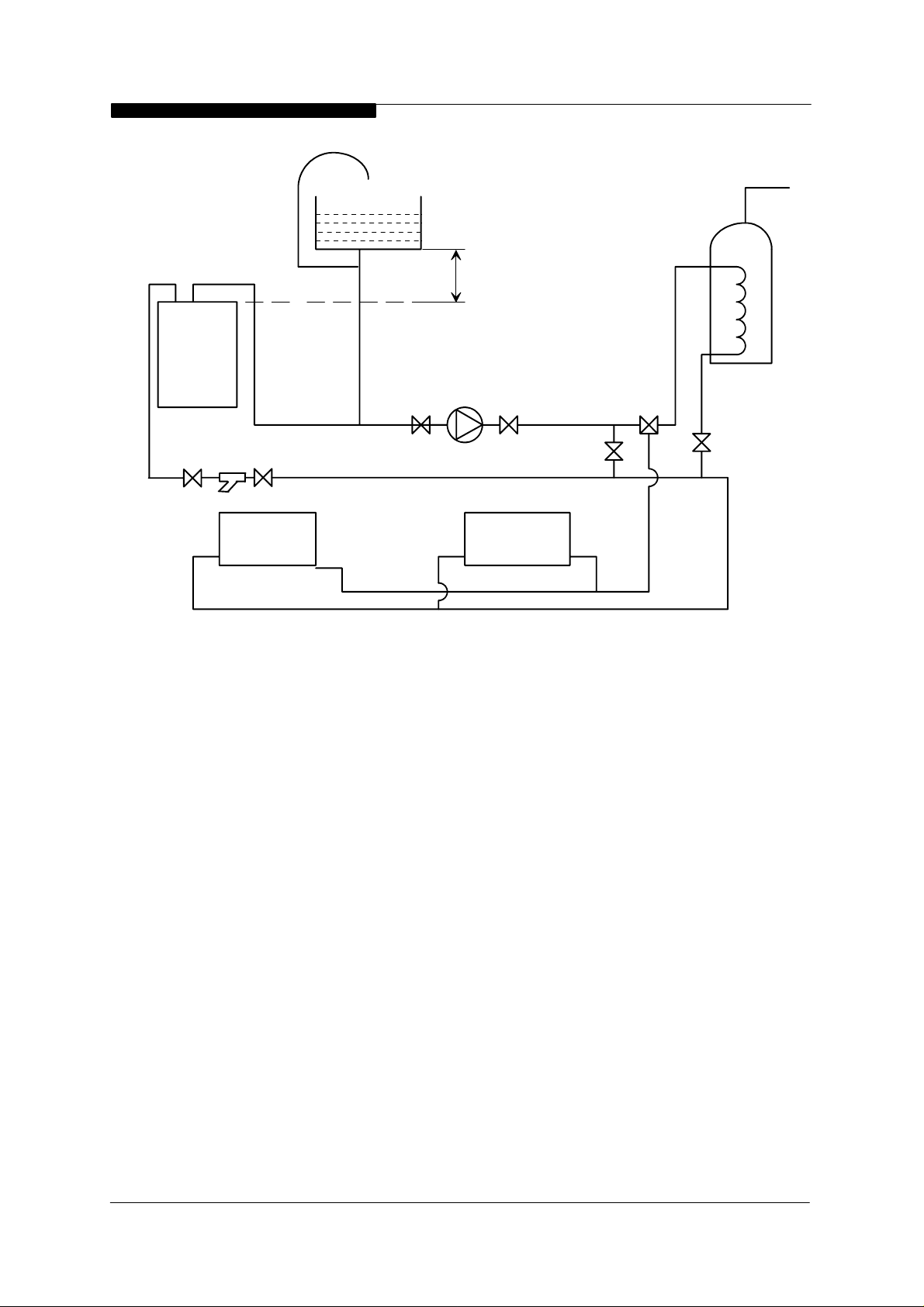
2.7.1 Open Vented Systems
A typical system is shown in Figure 2.7.1 which includes a combined feed and
vent. Note there must be no valve between the boiler flow and the open vent.
Note that the minimum static head required is 8 ft at the boiler flow pipe. If the
cold feed/vent is not brought to the flow pipe as shown, then the pressure loss
across the heat exchanger may have to be taken into account when estimating
the static pressure.
Although suitable for open vented systems with combined feed and vent
arrangements, the Keston is a low water content boiler. As such, any air
entrainement within the system water will produce boiler "kettling". It is
therefore recommended, if in any doubt, to consider the use of sealed
systems where possible.
Installation & Servicing Instructions
Page : 9
WD50/2/1997 Chapter 2 - Boiler Connections The Keston 50, 60 & 80 Condensing Boilers
Boiler
Expansion
Pipe
22mm pipe
(minimum)
Keston
Strainer
Rad. 2 Rad. 1
Expansion
Tank
Pump
Minimum
8ft Height
By-pass
Bal.
Valve
3 Way
Valve
Cylinder
L/S
2.7.2 Sealed Systems
Sealed systems must be designed in accordance with BS 5449 and BS 7074 Pt1.
A typical sealed system is shown in Figure 2.7.2. It must include :
(i) A safety valve fitted on the flow, adjacent to the boiler. It must be non
adjustable and preset to 3 bar. A drain pipe must be attached, at least as
big as the valve connection, and routed to drain in any area not
hazardous nor where it may be subject to freezing.
(ii) An expansion vessel complying with BS 4814 and sized in accordance
with the requirements of BS 5449 and BS 7074 Pt 1. The vessel must be
positioned on the inlet to the pump.
(iii) A filling point, in accordance with local water authority requirements.
(iv) A method of system make-up (automatic or manual), in accordance with
local water authority requirements.
(v) There must be no permanent connection of mains water to the boiler
system.
(vi) The installation must be designed to work with flow temperatures of up to
110
o
C.
All components of the system including the heat exchanger of the indirect
cylinder must be suitable for a working pressure of 3 bar and a temperature of
o
C. Care should be taken in making all connections that the risk of leakage is
110
minimised.
Figure2.7.1 : Open Vented System Diagram
Installation & Servicing Instructions
Page : 10
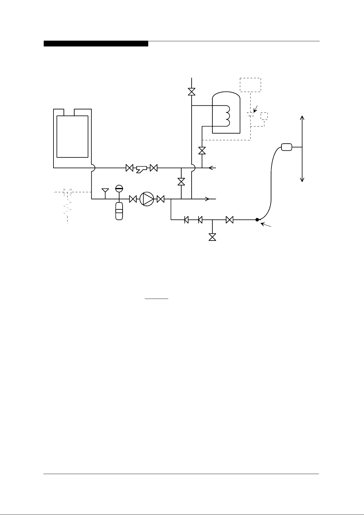
WD50/2/1997 Chapter 2 - Boiler Connections The Keston 50, 60 & 80 Condensing Boilers
Make -up vessel.
Max. capacity of
Air Vent
3 lt. (5pt)
Boiler
Keston
Drain
Cock
Safety
Relief
Valve
Pressure
Gauge
Expansion
Vessel
Strainer
By-pass
Bal.
Valve
Pump
Doubl e Check
Valve
Test Cock
Figure 2.7.2 : Sealed System Diagram
L/S
RETURN
HEATING CIRCUIT
FLOW
BS 1010:2
Stop T ap
Non-Return
Valve
Auto Air
Vent
Hose
Union
bib tap
Hosepipe
(disconnected
after filling)
Hose
Connector
2.7.3 Hot Water System (if applicable)
The hot water storage vessel must be of the indirect type (certain direct cylinders
can be used provided
they are suitably adapted by fitting an immersion
calorifier). DIRECT CYLINDERS MUST NOT BE USED. Further guidance is
provided in BS 1394. It is advisable to fit a lockshield valve on the cylinder return
to enable balancing of flow rate through the cylinder.
2.7.4 Boiler By-pass Piping
Boiler water flows are critical to the operation of the boiler. If flow cannot be
maintained through the system piping to meet the minimums required by the
boiler (see paragraph 2.7 (g)). Insufficient water flows through the boiler will cause
the boiler to "kettle" or even produce steam which can damage the heat
exchanger and will invalidate the heat exchanger warranty.
It is normally advisable to incorporate a boiler by-pass in the system, especially if
thermostatic radiator valves are used. The by-pass should be fitted with a
lockshield valve to permit balancing of the by-pass flow rate. The flow/return
differential should be 10
o
C to 15oC. The lockshield valve can be adjusted to
maintain this condition with the radiators fully heated.
Installation & Servicing Instructions
Page : 11
WD50/2/1997 Chapter 2 - Boiler Connections The Keston 50, 60 & 80 Condensing Boilers
2.7.5 Air Elimination
In the initial charge of water to the boiler system and in all subsequent additions
of water to the system some air will be dissolved in the water. As the water is
heated the air is driven out of the solution and will collect in high spots in the
system. These air bubbles can interfere with pumping and heat transfer and
must be eliminated.
Installation of air bleed valves at the high spot(s) in the system will allow for air
elimination when filling the system and will allow re-venting in a day or so after all
air has been driven out of solution.
Installation of an automatic air vent will ensure that any air, even minute
amounts, which subsequently enters the system will be automatically removed.
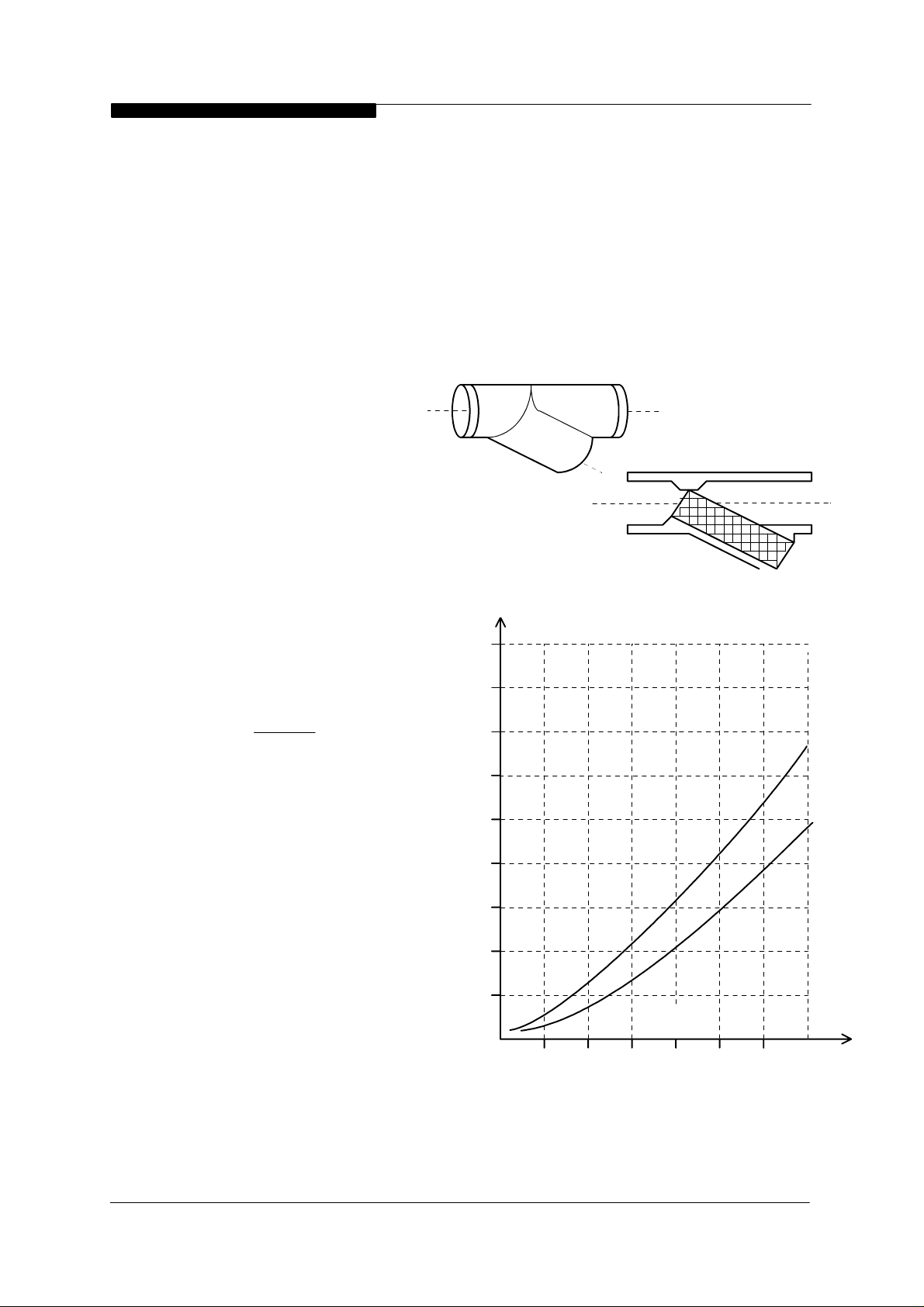
2.7.6 Strainers
Debris in the heating system
can cause noise if it enters the
heat exchanger. Fitting of a
Y-strainer ahead of the
circulating pump will trap any
debris left in the system and
will protect the pump from
damage.
2.7.7 Pump Selection
The Keston boilers have low
water content heat exchangers
with a high resistance to flow,
when compared with cast iron
heat exchanger boilers. As a
result selection of the correct
pump is essential
avoid localised boiling within
the heat exchanger. The
selected pump must be
capable of maintaining the
required flow rate for the boiler
against the pressure losses
contributed by the boiler and
the rest of the system.
Refer to the pressure loss/flow
rate Table 2.7.7 to determine
the pressure loss from the
boilers. Add this to the
pressure loss caused by the
rest of the system and select a
pump capable of meeting the
flow rate required at the total
pressure loss generated by the
boiler and the rest of the
system. The selected pump
must comply with BS 1394.
in order to
Y-Strainer will
collect an y loose
debris in the piping.
4.5
4.0
3.5
3.0
2.5
2.0
Pressure Loss - m
1.5
1.0
0.5
Figure 2.7.7 : Pressure Loss Graph
10 15 20 25 30
5
Water Flow - L/min
Figure 2.7.6 Strainers
Keston 80
Keston 50
Keston 60
35
Installation & Servicing Instructions
Page : 12
WD50/2/1997 Chapter 2 - Boiler Connections The Keston 50, 60 & 80 Condensing Boilers
It is important to note that the minimum flow rate must be maintained whenever the
boiler is firing. Systems using zone valves must be specifically designed to only fire the
boiler when the pump is running and the minimum flow rate can be achieved.
The Wilo Salmson Gold Star pump, or the Grundfoss 15/60 pump is normally suitable for
use with the Keston condensing boiler range. However, in all cases due consideration
must be given to the resistance to flow offered by the rest of the system when making a
final pump selection. This is particularly important when using small bore underfloor
heating pipework.
Keston 80Keston 60Keston 50Boiler Model
Min Flow Rate
Required
Pressure Loss
Through
Boiler
4.2 GPM
19.1 litres/min
3.2 ft
0.97m
9.7 kPa
5.0 GPM
22.7 litres/min
4.3 ft
1.3m
13 kPa
6.7 GPM
30.5 litres/min
9.0 ft
2.75m
27.5 kPa
Table 2.7.7 Pump Selection
2.8 FLUE SYSTEM
2.8.1 Design
Individual air supply and flue outlet pipes are used. The material used for flue
outlet &/or air inlet must be muPVC to BS 5255 and of an internal diameter of 38
mm.
Both flue outlet terminal and air inlet terminal are supplied and are illustrated in
Figure 2.8.1.
2.8.2 Maximum Lengths
The maximum lengths of both air inlet pipe and flue outlet pipe, when no bends
are used, are as detailed below.
Maximum Air Inlet Length : 10.0 m
Maximum Flue Outlet Length : 10.0 m
However, each bend used has an equivalent length that must be deducted from
the maximum straight length stated above.
A 92.5
Example:
o
sweep elbow is equivalent to 1.0m straight length.
Air inlet uses two 92.5o sweep elbows. Hence, maximum length permissible (ie
a+b in figure 2.8.2) = 10.0m - 1.0m - 1.0m = 8.0m
Flue outlet uses one 92.5
c+d in figure 7 = 10.0m - 1.0 m = 9.0m
Installation & Servicing Instructions
Page : 13
o
sweep elbow. Hence, maximum length permissible (ie
WD50/2/1997 Chapter 2 - Boiler Connections The Keston 50, 60 & 80 Condensing Boilers
2.8.3 Slope
'Horizontal' flue outlet pipework
MUST slope at least 2.5
FLUE
degrees (45 mm per metre
run) downwards towards the
boiler. Pipework can be
vertical. Only swept elbows can
be used.
c
d
Air inlet pipework can be truly
horizontal or vertical, or
sloping in a downward direction
towards the boiler but in this
case rain, etc, must
be
prevented from entering the
pipe. There must be no
troughs in any of the
pipework, whether it be air
inlet or flue outlet. If a 45
Figure 2.8.2 : Flue & Air Maximum Length Example
Keston
mm per meter slope is not
possible, contact Keston Boilers Technical Department for further guidance.
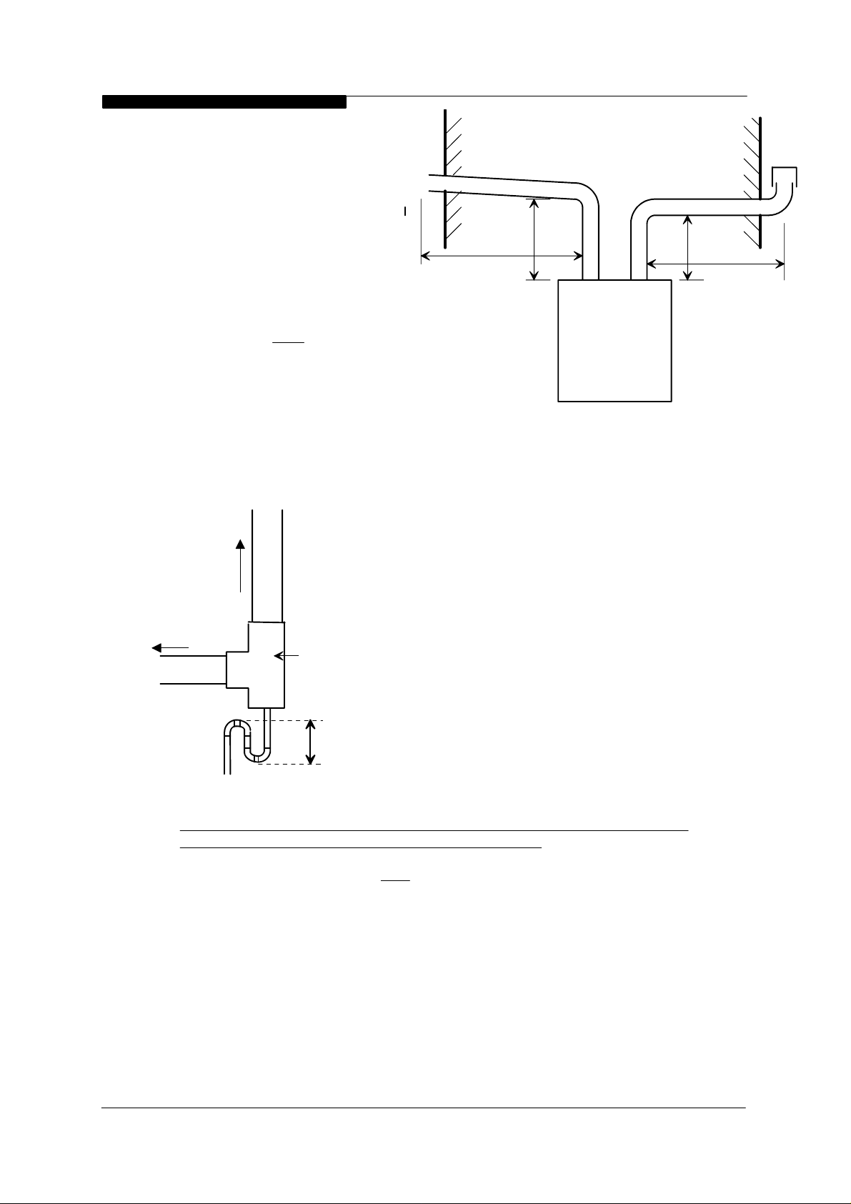
Due the low temperature of
the flue gases further condensate
will form within the flue system. Drain
Figure 2.8.3 :
Flue Condensate Drain
Point Example
points, with suitable traps, must
therefore be incorporated within the
flue system at the base of vertical
flue sections in excess of 2m. These
additional condensate drains must
To Termina l
be run to discharge as detailed in
section 2.11. Such drain points can
To Boiler
40mm Tee Fitting
be formed using standard muPVC
fittings. Refer to the example in
Figure 2.8.3.
AIR
b
a
6 in min.
2.8.4 Terminations
It is not advisable to terminate air
intake or flue within a car port area.
Air inlet terminals must be facing upwards and positioned to ensure only fresh air
is drawn into the boiler directly from outside the property.
The flue outlet terminal is designed to face outwards but can, if desired, be
adapted to face in any direction BUT
must not be directed in the region of the air
inlet.
The two terminals are subject to the requirements of BS 5440 Pt 1 for clearances
from features of the building although some can be decreased to the values
indicated. If either the air inlet or the flue outlet terminate at a height of less than
2m (6ft) above ground level the termination must be protected by a suitable
guard. The K4 terminal guard, manufactured by Tower Flue Components Ltd, is
suitable for this purpose and can be obtained from Keston Boilers.
The Keston Condensing Boiler, as with any condensing boiler, will generate a
condensate "plume" from the flue terminal in all weather conditions.
Consideration must therefore be given to the effect of this "plume" when
selecting a location for the flue terminal.
Installation & Servicing Instructions
Page : 14
 Loading...