

Keston Heat2 45, Heat2 45P, Heat2 55P, Heat2 55 User Manual
EVERYTHING IS POSSIBLE
USER GUIDE
Heat2 45, 45P, 55, 55P
When replacing any part on this appliance, use only spare parts that you can be
assured conform to the safety and performance specification that we require.
Do not use reconditioned or copy parts that have not been clearly authorised by Keston.
For the very latest copy of literature for specification and maintenance practices visit our website
www.keston.co.uk where you can download the relevant information in PDF format.
August 2019
220384 A02

CONTENTS
1. Introduction ................................................... 3
Safety .............................................................. 3
Electricity Supply ............................................. 3
Important Notes ............................................... 4
Minimum Clearances ....................................... 4
2. Boiler Operation ............................................ 5
Controls Diagram............................................. 5
To light the boiler ............................................. 6
Operating Status.............................................. 7
Settings............................................................ 8
3. Installer Connections .................................. 20
4. Faults ............................................................ 21
Faults - Hardware (Thermistors, Actuators)... 22
Faults - Temperature Supervisions ................ 23
Faults -
Faults - Internal System................................. 25
5. General Information .................................... 26
To shut down the boiler .................................. 26
To relight the boiler ........................................ 26
Frost Protection ............................................. 26
Boiler Overheat Thermostat .......................... 29
Condensate Drain.......................................... 26
Escape of Gas ............................................... 27
Cleaning ........................................................ 27
6. System Set up information ......................... 28
System (Flame, Fan, Hydraulic, etc.)
. 24
2
KESTON HEAT2
45, 55
45, 55P
Natural Gas & Propane
Destination Countries: GB, IE, RO
1. INTRODUCTION
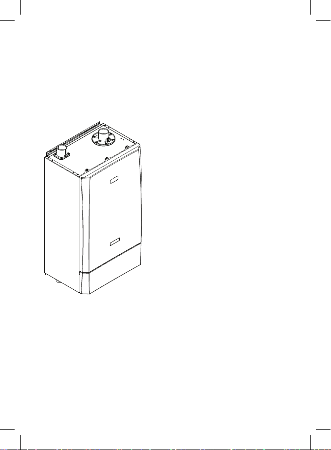
The KESTON HEAT2 is a wall mounted,
room sealed, super efcient condensing
boiler featuring full sequence automatic
spark ignition and fan assisted
combustion.
Due to the very high efciency, condensate
is produced from the ue gases and this
is drained to a suitable disposal point
through the plastic waste pipe at the
bottom of the boiler. A condensate
‘plume’ will also often be visible at the
ue terminal.
SAFETY
Current Gas Safety (Installation & Use)
Regulations or rules in force.
In your own interest, and that of safety, it
is the law that this boiler must be installed
and maintained by a suitably qualied
Gas Safe registered engineer or in IE a
competent person, in accordance with the
above regulations.
The appliance should be serviced at
least once a year by a suitably qualied
Gas Safe registered engineer or in IE a
competent person.
It is essential that the instructions in this
booklet are strictly followed, for safe and
economical operation of the boiler.
ELECTRICITY SUPPLY
The appliance must be earthed.
Supply 230 V - 50 Hz, 4 Amp fuse.
This appliance is intended to be connected
to the supply via a double-pole switch,
having a 3mm contact separation in both
poles, serving only the boiler and system
controls.
3

IMPORTANT NOTES
• This appliance must not be operated
without the casing correctly tted and
forming an adequate seal.
• If the boiler is installed in a
compartment then the compartment
MUST NOT be used for storage
purposes.
• Do not store objects around or on the
boiler, and keep access clear at all
times.
• Do not obstruct ventilation ducts,
condensate pipework, grilles or
openings in the boiler room, room
space or compartment that the
appliance is installed in, or the
passage of combustion and ventilation
to the boiler.
• Do not turn off the boiler if it is to be
left unattended in frosty weather.
• If it is known or suspected that a fault
exists on the boiler then it MUST NOT
BE USED until the fault has been
corrected by a suitably qualied Gas
Safe registered engineer or in IE a
competent person.
• Flammable materials must not
be placed in close proximity to
the appliance. Materials giving off
ammable vapours must not be stored
in the same room as the appliance.
This appliance can
•
be used by children 8
years and above. Also
persons with reduced
physical, sensory or
mental capabilities, or
lack of experience and
knowledge, provided
they have been given
supervision or instruction
concerning use of the
appliance in a safe
way and understand
the hazards involved.
Children shall not play
with the appliance.
Cleaning and user
maintenance shall not be
made by children without
supervision.
• Children should be supervised to
ensure that they do not play with the
appliance.
In cases of repeated or continuous shutdown
a suitably qualified Gas Safe registered
engineer or in IE a competent person
should be called to investigate and rectify
the condition causing this and carry out an
operational test after each intervention on the
device. Only the manufacturers original parts
should be used for replacement.
MINIMUM CLEARANCES
Clearances of 450mm above, 300mm below,
25mm at the sides and 450mm at the front
of the boiler casing must be allowed for
servicing.
4
2. BOILER OPERATION
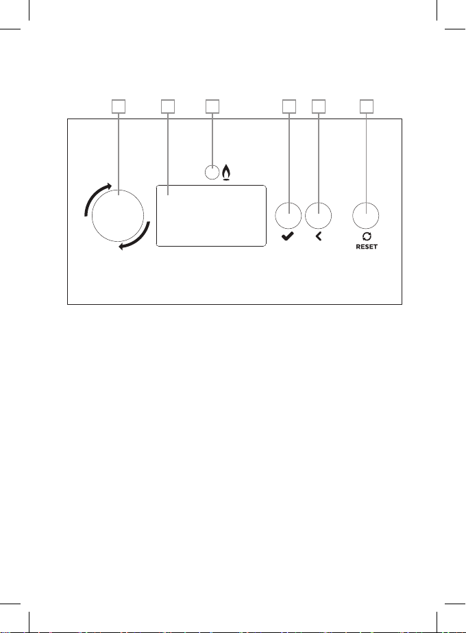
CONTROL DIAGRAM
A B C D E F
BACK
OK
A. ROTARY KNOB
• Enter a menu, if in the normal
operation screen, and highlight the
rst menu item.
Scroll up (anti-clockwise) or down
•
(clockwise) in a menu
• Change the value in parameter
setting.
• If an error is showing in the title
bar, scroll to the associated error
screen(s), and return.
B. LCD DISPLAY SCREEN
• Menu and status display.
C. BURNER LED
• Will be on if the burner is lit.
D. SELECT BUTTON
• Enter a menu, if in the normal
operation screen, and highlight the
rst menu item.
• Enter the highlighted menu (sub
menu or parameter), if in a menu or
sub menu.
• If in a parameter setting, select a
parameter which will then ash for
adjustment, once adjusted using the
rotary knob press again to store and
move on.
E. BACK BUTTON
• In a menu, return to the previous
menu layer.
• In parameter setting, exit the
parameter without storing the value.
• In a guided assistant, go back to the
previous screen.
F. RESET BUTTON
• Reset the associated boiler module
error, if a resettable (lockout) error is
active.
• Return to the normal operation
screen.
5

TO LIGHT THE BOILER
A. Stand alone boiler, or a master
boiler in a cascade, or a master
boiler with an extension module:
Set the operating mode in the plant
menu operating mode to: Automatic
Ensure that there is a demand
present on the boiler from the
external controls, depending upon the
conguration.
If there are no local heating or DHW
circuits, set the plant / operating mode
to: Day
If there are local heating circuits,
set one of them - heating circuits /
HC1 Boiler 1.1 or HC2 Boiler 1.2 /
Operating mode to: Day
If there is a local DHW circuit set the
DHW / Operating mode / DHW1 Boiler
1 to: Day
If there is an extension module
congured with Heating circuits or
DHW circuits set the Operating mode
to: Day
e.g. Heating circuits / Operating mode
/ HCx EMy.z
DHW / Operating mode / DHWx
EMy.z
Key: x is the Heating or DHW circuit
number, y is the Extension Module
designation and z its local Heating or
DHW circuit designation.
B. Slave Boiler in a Cascade:
Refer to the Installation manual.
The boiler will commence the ignition sequence, supplying heat to the system. Ensure that
the controls are then set to the operating mode required.
Note. Not all menus and options will be available depending upon the access level selected.
6
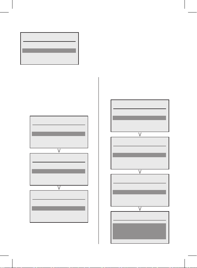
OPERATING STATUS
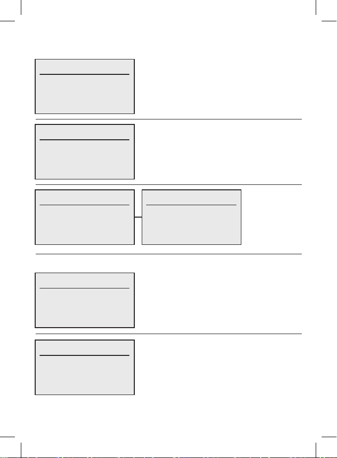
The status screens are dependent upon the boiler conguration, they are shown below:
KESTON HEAT 2 55kW
Operation: Htg. with temp.
Master non cascade
Flow Set point: 40.2ºC
Flow temp: 40.2ºC
KESTON HEAT 2 55kW
Operation: Htg. with capacity
Capacity Set point: 40%
Master / Non cascade / Slave
Capacity: 0%
Flow temp: 40.2ºC
KESTON HEAT 2 55kW
Operation: Htg. with temp.
Voltage: 5.6V
Flow Set point: 40.2ºC
Flow temp: 40.2ºC
KESTON HEAT 2 55kW
Operation: Htg. with capacity
Voltage: 5.6V
Capacity Set point: 40%
Capacity: 0%
Master non cascade,
0-10V control
The heating circuits and DHW circuits also have status screens associated with them. e.g.
KESTON HEAT 2 55kW
Status: OpenTherm
Operation: Day
Room set point: 20.0ºC
Menu item: Heating circuit / Status / Summary /
HC1 Boiler 1.1
Flow set point: 60.0ºC
KESTON HEAT 2 55kW
Status:
Operation: Night
Tank temperature: 45.0ºC
Menu item: DHW / Status / Summary / HC1
Boiler 1.1
Flow set point: 30.0ºC
7
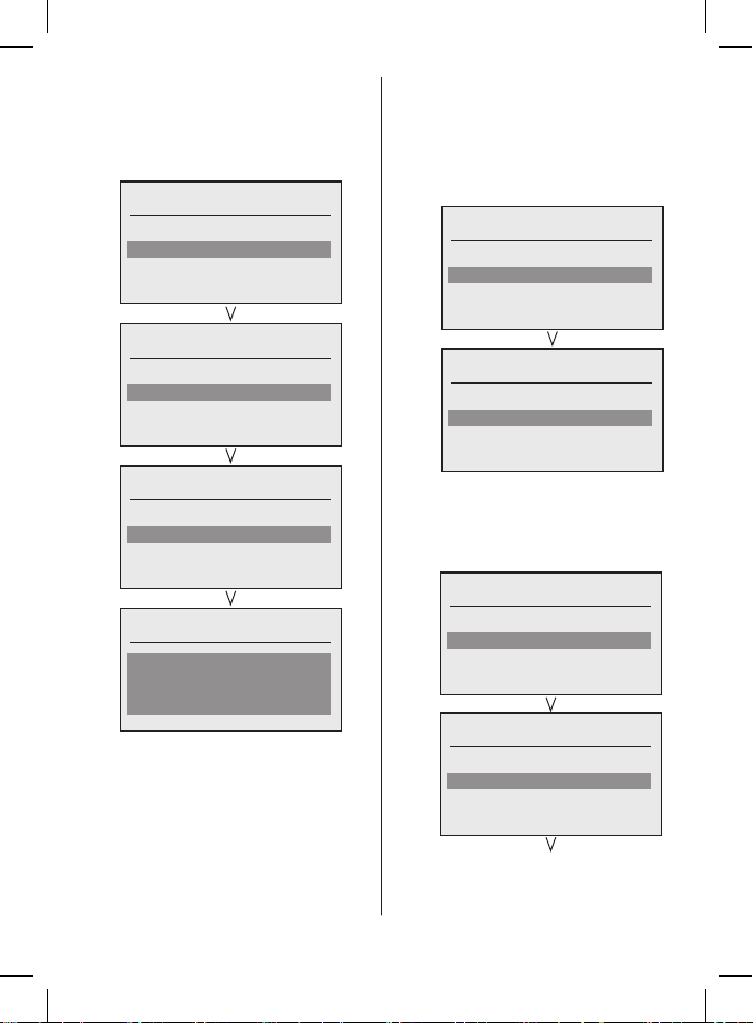
SETTINGS
1. Heating Circuits
Menu
Plant
Heating circuits
DHW
Each heating circuit that is congured has the following settings:
a. Operating mode selection:
Every heating circuit can be
individually set to one of the
following modes;
Standby / Time clock single day
/ Time clock multiple day / Day /
Night.....e.g.:
Heating circuits
Status
Operating mode
Room temperature
Flow temperature
b. Room temperature
A temperature can be set for each
heating circuit for the following periods:
Day / Night / Holiday.....e.g.:
Heating circuits
Operating mode
Room temperature
Flow temperature
Settings
Room temperature
Heating circuits
HC1 Boiler 1.1
HC2 Boiler 1.2
HC1 Boiler 1.1
Operating mode
Standby
HC1 Boiler 1.1
HC2 Boiler 1.2
HC1 Boiler 1.1
Room temperature. day
Room temperature. night
Room temperature. holiday
Room temperature, day
20.0
8
c. Flow temperature
A maximum ow temperature can be
set for each heating circuit for the
following periods
Day / Night / Holiday.....e.g.:
Heating circuits
Room temperature
Flow temperature
Settings
Time clock
Flow temperature
HC1 Boiler 1.1
HC2 Boiler 1.2
HC1 Boiler 1.1
Flow temperature. day
Flow temperature. night
Flow temperature. holiday
Flow temperature, day
70.0
d. Settings
Each heating circuit has a number
of settings that can be congured.
Most settings are only accessible
at Installer access levels.
Day / Night / Holiday.....e.g.:
Heating circuits
Flow temperature
Settings
Time clock
Holiday program
Settings
HC1 Boiler 1.1
i. Preheat - Preheat can be enabled
for a heating circuit and a
maximum time can be set.
HC1 Boiler 1.1
Preheat
Heating limit
Room temp. switch diff.
Preheat
Preheat switch
Maximum preheat time
CONTINUED OVERLEAF
9
 Loading...