

Keston C55P Installation and Servicing Manual
WD265/0/2002 The Keston C40, C40P, C55 & C55P
Fan Powered High Efficiency
Modulating Domestic Condensing Gas Boiler
Installation And Servicing Instructions
C40, C40P, C55 & C55P Models
CE/PI No : 87BN14
C40 - GC No : 41-930-07
C40P - GC No : 41-930-08
C55 - GC No : 41-930-09
C55P - GC No : 41-930-10
These instructions must be left either with
the user or next to the site gas meter.
34 West Common Road
Hayes, Bromley, Kent BR2 7BX
Tel. +44 (0)20 8462 0262 Fax. +44 (0)20 8462 4459
email : info@keston.co.uk web : www.keston.co.uk
COMPLIANT WITH BUILDING REGULATION PART L1 & L2 2002
SEDBUK A RATED

WD265/0/2002 The Keston C40, C40P, C55 & C55P
CONTENTS
Section Description
0 HANDLING INSTRUCTIONS
0.1 List of contents
0.2 Recommended handling procedure
1 GENERAL INSTRUCTION
1.1 Description
1.2 Boiler Schematic
1.3 Related Documents
1.4 Physical Data
1.5 Performance Data C40 and C40P
1.6 Performance Data C55 and C55P
1.7 Optional Accessories
2 BOILER LOCATION
2.1 Dimensions & Minimum Clearances
2.2 Service Connections
2.3 Position
2.4 Electrical
2.5 Boiler Size Selection
2.6 Gas Supply
2.7 Water Systems
2.8 Flue System
2.9 Air Supply
2.10 Compartment Installation
2.11 Condensate Drainage
3 INSTALLATION OF THE BOILER
3.1 Wall Mounting Bracket
3.2 Mounting The Boiler
3.3 Assembly Practice
3.4 Installing Flue And Air Pipes
3.5 Condensate Drainage
3.6 Water System
3.7 Gas Supply
3.8 Electrical Supply
3.9 Exchanging A Boiler
Page : i

WD265/0/2002 The Keston C40, C40P, C55 & C55P
4 COMMISSIONING OF THE BOILER
4.1 Initial Flushing
4.2 Gas Supply
4.3 Electrical Installation
4.4 LP Gas
4.5 Initial Firing
4.6 Hot Flushing
4.7 Combustion Testing
4.8 Checking The Gas Pressure
4.9 Timing The Gas Meter
4.10 Handing Over To The User
5 FAULT FINDING
5.1 Electrical Control Sequence
5.2 Normal Operation
5.3 Fault Modes
5.4 Functional Flow Wiring Diagram
5.5 Electrical Wiring Diagram
5.6 Illustrated Wiring Diagram
5.7 Exploded Assembly Diagrams
6 SERVICING
6.1 Pre Service Checks
6.2 Recommended Routine Service
7 REPLACEMENT OF PARTS
7.0 General
7.1 Precautions
7.2 Access
7.3 Replacement Procedure
7.4 Electrical Components
7.5 Spark Ignition/Flame Detection Electrode
7.6 Burner
7.7 Heat Exchanger
7.8 Condensate Trap
7.9 Pump
8 SPARE PARTS LISTINGS
9 GAS BOILER COMMISSIONING CHECKLIST
Page : ii

WD265/0/2002 The Keston C40, C40P, C55 & C55P
0. HANDLING INSTRUCTION
0.1 LIST OF CONTENTS
The Keston C40 and C55 are supplied almost totally pre-assembled. Since the units use
standard 50 mm muPVC pipe for the flue and air intake systems the boiler is packed in a
single box without additional flue kit. All additional components are packed inside the boiler
cabinet itself. The following is a list of components and their location in the boiler cabinet
Equipment List
Item Quantity Location
Wall Bracket Rawl Plugs 5 Inside accessories bag
Wall Bracket Wall Fixing Screws 5 Inside accessories bag
Wall Mounting Bracket 1 Secured to inside right hand
side of boiler case
Wall Mounting Bracket Nuts 2 Inside accessories bag.
Wall Mounting Bracket Washers 2 Inside accessories bag
Gas Cock (22 mm cxc) 1 Inside accessories bag
50 mm muPVC Air/Flue Terminals 2 Inside accessories bag
Air Inlet Spigot (50 mm) 1 Inside accessories bag
Air Inlet Spigot Gasket 1 Inside accessories bag
Air Inlet Spigot Screws 4 Inside accessories bag
Flue Spigot Screws 2 Inside accessories bag
Cabinet Cable Entry Clamps 2 Inside accessories bag
User Control Knobs 2 Inside accessories bag
Document List
Item Quantity Location
User Instructions 1 In A4 envelope
Registration of Purchase/Extended Warranty 1 In A4 envelope
Installation Template 1 In document bag
Remove the cabinet shell by removing the four retaining screws in the top of the cabinet and
the three retaining screws in the bottom of the cabinet.
0.2 Recommended Handling Procedure
Before hanging the appliance on the wall it is best to store the appliance laid on its back with
the casing on. When ready to hang the boiler on the wall remove the casing and place to one
side. At this stage it is assumed that the wall bracket is correctly secured on the wall face.
a) Have the wall bracket nuts and washers to hand so that they can be accessed whilst
holding the boiler in position on its mounting bracket.
b) The boiler has a dry weight of 61.5kg (136 lbs) and will therefore require at least two
people to lift without the use of lifting aids.
c) Lift the boiler by gripping at the four corners of the boiler back plate. When lifting this
appliance the back should be kept straight at all times. Avoid twisting at the waist reposition the feet instead. Avoid upper body bending when holding the appliance and
keep the boiler as close to the body as possible.
d) Lift the boiler and locate onto the two studs of the wall mounting bracket.
e) Hold the boiler on the wall bracket by applying pressure onto the front surface of the heat
exchanger.
f) Place the wall mounting bracket washers over the bracket studs protruding through the
back plate of the boiler.
g) Secure the boiler onto the wall bracket by fixing the wall mounting bracket nuts onto the
wall bracket studs. These should be tightened well.
Page : iii

WD265/0/2002 The Keston C40, C40P, C55 & C55P
In the event the appliance must be fitted by one operative the integral circulating pump head
and complete combustion fan/gas valve/venturi assembly can be removed from the appliance
prior to lifting. However, the resulting weight will still be higher than considered acceptable for
a one-man lift.
Safety footwear and gloves are recommended PPE when lifting this appliance.
The C40 and C55 boilers can be fitted in compartments with very small clearances required
around the appliance (refer to Section 1.4). Due consideration should therefore be given to
access within the compartment for lifting and positioning.
Page : iv

WD265/0/2002 Chapter 1 : General Instruction The Keston C40, C40P, C55 & C55P
1. GENERAL INSTRUCTION
1.1 DESCRIPTION
The Keston C40 and C55 are unique in concept and design. They comprise a high
efficiency stainless steel heat exchanger coupled with a low emissions burner to deliver
ultra high efficiency condensing mode operation within a compact wall hung cabinet. The
unit automatically adjusts gas and air rate according to demand to give an output in the
range of 11kW to 40kW (C40 & C40P) and 14kW to 55kW (C55 & C55P). The integral
Grundfos pump is automatically controlled to best match water flow rate to heat output &
further increase appliance efficiency. In addition, they feature an optional connection for
an outside sensor to enable the boilers inbuilt weather compensation option. Separate
inputs are provided for hot water and central heating demand signals to enable different
temperature levels to be set (ideal for underfloor heating systems). While the application
for which the C40 and C55 were designed is the same as those which other boilers are
used, the Keston C40 and C55 have the added advantage of very high efficiency, and
small diameter plastic flue which can be extended up to 45 metres horizontally or
vertically.
The Keston C40 and C55 uses a variable speed combustion blower to deliver a premix of
gas and air to a downward firing burner in a high efficiency, single pass heat exchanger.
The flue system is room sealed and fan powered. The ignition is direct spark and fully
automatic. The boiler housing is not waterproof and should be installed in a position
where it will always be dry. Combustion air is drawn from the cabinet which is connected
to outside atmosphere via a small diameter plastic intake pipe. The cabinet therefore
remains under negative pressure at all times the boiler is operating.
The boiler is suitable for connection to open vented or, preferably, sealed systems.
The boiler heat exchanger is made from highly corrosion resistant stainless steel in
corrugated pipe form which provides massive surface area within a compact dimension.
The hot combustion gases from the down firing burner pass around the stainless steel
pipes imparting heat into the system water. The integral variable speed Grundfos pump
within the appliance cabinet ensures the heat exchanger receives correct water flow when
firing. The C40 and C55 are not high water content boilers and do not contain the metal
mass, or water volume, of a cast iron or steel boiler. This boilers are of low mass and low
water content and therefore responds faster when there is a call for heat. The C40 and
C55 feature full user diagnostics, integral frost protection function, automatic pump and
fan exercise in periods of inactivity, anti cycle control, dry fire protection and connections
for remote lockout and run monitoring (optional accessory).
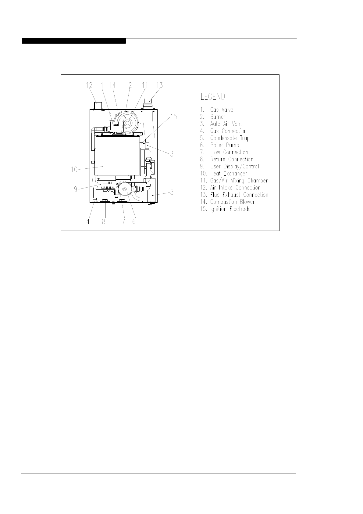
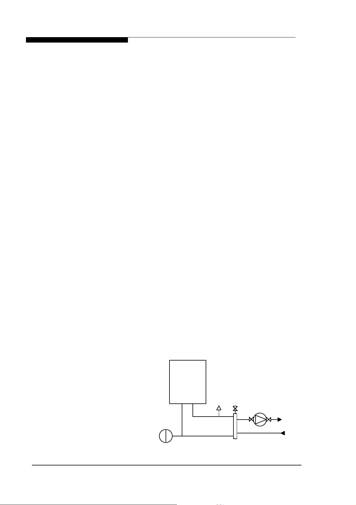
1.2 BOILER SCHEMATIC
Air is drawn into the boiler through a 50 mm muPVC (BS5255 and/or BSEN1566-1 and
BSEN1329) plastic pipe or, alternatively, via a 75mm composite plastic pipe. Gas is mixed
with combustion air at the inlet to the fan. The gas flow is automatically regulated by the
gas valve according to the air flow generated by the fan. The gas and air are thoroughly
mixed in the blower and fed into the burner located at the top end of the heat exchanger
module. The gas and air mixture is ignited by a direct spark ignition control system and
burns with a blue flame just off the surface of the burner. As the hot products of
combustion pass downwards, they are cooled by exchanging heat with the circulating
water which enters the heat exchanger at the bottom of the heat exchanger. The optimum
heat input is detected by monitoring flow and return temperatures and is adjusted by
controlling the speed of the fan. The optimum pump speed is also detected and
automatically selected by the boiler.
When the return water temperature is below 55oC, part of the water vapour in the
combustion products will condense inside the heat exchanger, thus increasing the boiler
efficiency further by releasing the latent heat of condensation. This condensate falls to the
bottom of the heat exchanger where it is separated from the flue gases and exits from the
boiler through the condensate drain. Any condensate formed in the flue runs back down
Installation & Servicing Instructions Page : 1
WD265/0/2002 Chapter 1 : General Instruction The Keston C40, C40P, C55 and C55P
the flueway and is drained at the base of the flue connection to the heat exchanger or
drain points within the flue.
Fig. 1.2 - Boiler Layout
The condensate is very slightly acidic (about the same acidity as vinegar) and should be
piped in a plastic pipe. It is not harmful to the waste disposal system and may be disposed
of as normal waste water.
The flue gases are piped in a 50 mm muPVC (BS5255 and/or BSEN1566-1 and
BSEN1329) plastic or, alternatively, 75mm composite plastic pipe to the outside. The
temperature of the flue gases are usually around 5oC to 10oC above the temperature of
the return water. The flue pipe should be terminated outside the building from where they
cannot re-enter the building or any other adjacent building.
The heating level may be controlled by room thermostats, hot water calorifier thermostats,
programmer time clocks and energy management systems. A Keston room controller can
be connected which will provide enhance controls such as room compensation and
optimum start to further increase efficiency and comfort levels.
The C40 and C55 feature an integral frost protection function which will operate the pump,
regardless of the external controls, should the boiler temperature fall below 7oC. In the
event the boiler temperature falls below 3oC the boiler will also fire. This is to avoid
damage to the boiler through freezing of boiler water. The boiler will turn off when the flow
temperature exceeds 10oC.
The C40 and C55 feature an integral pump exercise function which will run the pump,
without firing the boiler, for 10 seconds in the event the boiler is on standby for in excess
of 24 hours without firing. This is to help prevent seizing of the pump due to long periods
of inactivity.
1.3 RELATED DOCUMENTS
The Keston C40 and C55 Condensing Boiler must be installed in accordance with the
current issue of the Gas Safety (Installation and Use) Regulations 1996, current IEE
Wiring Regulations, Building Regulations, Building Standards (Scotland) Consolidation,
and the Bye Laws of the local Water Undertaking.
Installation & Servicing Instructions Page : 2
WD265/0/2002 Chapter 1 : General Instruction The Keston C40, C40P, C55 & C55P
In addition, due account must be taken to the following Codes Of Practice:
BS 6891 : Gas Supplies
BS 6798 : Installation Central Heating Boilers
BS 5449 : Installation Pumped Central Heating
BS 5546 : Installation Domestic Hot Water
BS 5440.1 : Flues
BS 5440.2 : Air Supply
BS 5482.1 : Domestic Propane and Butane Burning Installations
BS 7074.1 : Expansion Vessels
BS 7593 : Treatment of Water in Hot Water Central Heating
Systems
BS 7671 : Requirements for Electrical Installations. IEE Wiring
Regulations 16th Edition.
For Timber Framed Buildings, British Gas Publications DM2. Also British Gas
Publications 'Guidance Notes For The Installation Of Domestic Gas Condensing
Boilers' and 'Specification For Domestic Wet Central Heating Systems'.
Cabinet Height mm 720
Cabinet Width mm 520
Cabinet Depth mm 320
Top Clearance mm 150
Side Clearance mm 25
Base Clearance mm 150
Front Clearance (for servicing) mm 305
Weight - Full kg / (lbs) 70.5/(157.8)
Weight - Empty kg / (lbs) 61.5/(135.8)
Flow and Return Connection Rp 1" F
Gas Connection Rp 0.75" F
Condensate Connection mm 22mm plastic overflow
IP Rating IP20 (IPX0)
Flue and Air Intake Material 50mm muPVC (BS5255 and/or BSEN1566-1 and BSEN1329)
Flue Pipe Size (nominal bore) mm / (in) 50 / (2)
Air Intake Pipe Size (nominal bore) mm / (in) 50 / (2)
Max. Air Intake Length m 29
Max. Flue Outlet Length m 15
Max. Total Flue Outlet and Air Intake Length m 30
Flue and Air Intake Material 75mm Keston Composite
Flue Pipe Size (nominal bore) mm / (in) 75 / (3)
Air Intake Pipe Size (nominal bore) mm / (in) 75 / (3)
Max. Air Intake Length m 87
Max. Flue Outlet Length m 45
Max. Total Flue Outlet and Air Intake Length m 90
1.4 PHYSICAL DATA - C40 and C55
Keston Boilers Ltd declare that there are no substances harmful to health within the
appliance or used during the production of the appliance.
The C40 and C55 are intended for domestic and commercial EMC environments and on a
governed G20 meter supply.
The C40P and C55P is intended for domestic and commercial EMC environments and on a
governed G31 supply.
Installation & Servicing Instructions Page : 3
WD265/0/2002 Chapter 1 : General Instruction The Keston C40, C40P, C55 and C55P
1.5 PERFORMANCE DATA - C40 & C40P
C40 C40P
Nat. Gas (G20) LPG (G31)
Min. Input (Gross CV) kW/(Btu/h) 12.9/(43,900) 12.6/(43,000)
Max. Input (Gross CV) kW/(Btu/h) 45.6/(155,600) 43.2/(147,400)
Max. Output To Water
(80/60oC Flow/Return) kW/(Btu/h) 40.3/(137,600) 39.1/(133,300)
(50/30oC Flow/Return) kW/(Btu/h) 44.9/(153,400) 43.2/(147,400)
Min. Output To Water
(80/60oC Flow/Return) kW/(Btu/h) 11.3/(38,500) 11.4/(38,800)
(50/30oC Flow/Return) kW/(Btu/h) 12.6(43,000) 12.6(43,000)
Max. Burner Press.-Hot (Factory Preset) mbar/(in w.g) 0 0
Gas Consumption After 10 mins l/s / (Ft3/hr) 1.21/(153.4) 0.451/(57.4)
Max. Operating Flow Temp.
o
C 82.00 82.00
Max. Head (Open Systems) m / (ft) 30.50 / (100) 30.50 / (100)
Max. Press. (Sealed System) bar 2.70 2.70
Min. Head (Open Systems) m 3.0 3.0
Inlet Gas Pressure mbar/(in w.g) 20.0 / (8.0) 37.0/(14.8)
Recommended Temp Diff.
o
C 8 to 20 8 to 20
Electrical Supply 230V 50Hz 230V 50Hz
Power Consumption (Max) W 260 260
Power Consumption (Standby) W 8 8
Type of Gas G20 Natural Gas G31 LPG
Optimum Flue Gas CO2 Level % 8.3 9.9
Expected CO/CO2 Ratio (at max rate) 0.001 0.0013
Destination Countries GB/IE GB/IE
SEDBUK Efficiency 90.4% 92.5%
1.6 PERFORMANCE DATA - C55 & C55P
C55 C55P
Nat. Gas (G20) LPG (G31)
Min. Input (Gross CV) kW/(Btu/h) 14.3/(48,800) 14.8/(50,500)
Max. Input (Gross CV) kW/(Btu/h) 56.5/(192,800) 53.4/(182,300)
Max. Output To Water
(80/60oC Flow/Return) kW/(Btu/h) 49.7/(169,700) 48.0/(163,900)
(50/30oC Flow/Return) kW/(Btu/h) 55.2/(188,500) 53.4/(182,300)
Min. Output To Water
(80/60oC Flow/Return) kW/(Btu/h) 12.5/(42,900) 12.9/(44,100)
(50/30oC Flow/Return) kW/(Btu/h) 14.3/(48,800) 14.8/(50,500)
Max. Burner Press.-Hot (Factory Preset) mbar/(in w.g) 0 0
Gas Consumption After 10 mins l/s / (Ft3/hr) 1.50/(190.1) 0.54/(68.3)
Max. Operating Flow Temp.
o
C 82.00 82.00
Max. Head (Open Systems) m / (ft) 30.50 / (100) 30.50 / (100)
Max. Press. (Sealed System) bar 2.70 2.70
Min. Head (Open Systems) m 3.0 3.0
Inlet Gas Pressure mbar/(in w.g) 20.0 / (8.0) 37.0/(14.8)
Recommended Temp Diff.
o
C 8 to 20 8 to 20
Electrical Supply 230V 50Hz 230V 50Hz
Power Consumption (Max) W 260 260
Power Consumption (Standby) W 8 8
Type of Gas G20 Natural Gas G31 LPG
Optimum Flue Gas CO2 Level % 8.8 10.2
Expected CO/CO2 Ratio (at max rate) 0.001 0.0013
Destination Countries GB/IE GB/IE
SEDBUK Efficiency 90.2% 92.2%
Installation & Servicing Instructions Page : 4

WD265/0/2002 Chapter 1 : General Instruction The Keston C40, C40P, C55 & C55P
Seasonal Efficiency (SEDBUK) = 90.4% (C40), 92.5% (C40P), 90.2% (C55) & 92.2 (C55P)
This value is used in the UK Government's Standard Assessment Procedure (SAP) for
energy rating of dwellings. The test data from which it has been calculated have been
certified by Advantica Technologies Ltd
IMPORTANT
This product contains ceramic fibre boards, which although not regarded as a risk, contain
ceramic fibre which may cause temporary irritation to eyes, skin and respiratory tract. The
fibres are held in place by inorganic binders. Therefore as long as the boards are not
disturbed they will not be released. Since the boards are non-servicable parts there should
be no risk.
To ensure that the release of fibres from these RCF articles is kept to a minimum, during
installation and servicing we recommend that you use a HEPA filtered vacuum to remove
any dust accumulated in and around the appliance before and after working on the appliance. When replacing these articles we recommend that the replaced items are not broken
up, but are sealed within heavy duty polythene bags, and clearly labelled as RCF waste.
RCF waste is classed as a stable, non-reactive hazardous waste and may be disposed at a
landfill licensed to accept such waste. Protective clothing is not required when handling
these articles, but we recommend you follow the normal hygiene rules of not smoking,
eating or drinking in the work area and always wash your hands
before eating or drinking.
BENCHMARK INITIATIVE
As part of the industry wide “Benchmark” initiative C40 & C55 boilers manual includes Gas Boiler
Commissioning Checklist (Chapter 9). This form should be completed by your installer at the
end of the installation and commissioning process. The details of the Checklist will be required in
the event of any warranty work being required. There is also Service Interval Record (Chapter 9)
to be completed after each annual service visit.
These forms (Chapter 9) should be kept in a safe place for the life of the boiler.
CORGI INFORMATION
The boiler should be installed and serviced only by CORGI registered operatives. All CORGI
registered Installers carry a CORGI ID card and have a registration number. Both should be
recorded in your boiler manual (Chapter 9: GAS BOILER COMMISSIONING CHECKLIST).
You can check your installer by calling CORGI direct on 01256 372300.
1.7 OPTIONAL ACCESSORIES
A range of accessories are available from Keston Boilers Ltd to compliment an installation.
Terminal wall sealing collars are available to make good the external all face whilst working from
the inside of the building using 50mm muPVC (BS5255 and/or BSEN1566-1 and BSEN1329) pipe
or 75mm (actual dimensions are int.dia. = 68mm, ext.dia. = 78mm) Keston Composite pipe.
Stand-off frames are available to leave a 50mm gap behind the boiler to allow routing of pipes
behind the boiler.
Description Part Number
Flue Terminal Wall Sealing Collar (50mm) C.08.0.00.07.0
Air Terminal Wall Sealing Collar (50mm) C.08.0.00.07.0
50/75mm Flue Adapter C.17.2.00.60.0
Flue Outlet Terminal (75mm) C.17.2.26.00.0
Air Inlet Terminal (75mm) C.17.2.26.00.0
Stand Off Back Plate C.17.0.02.00.0
Outside Temperature Sensor C.17.4.17.00.0
Keston Chronotherm Room Controller C.17.4.21.00.0
Installation & Servicing Instructions Page : 5
WD265/0/2002 Chapter 2 - Boiler Location The Keston C40, C40P, C55 & C55P
All dimensions in mm.
mm
2. BOILER LOCATION
All dimensions in mm.
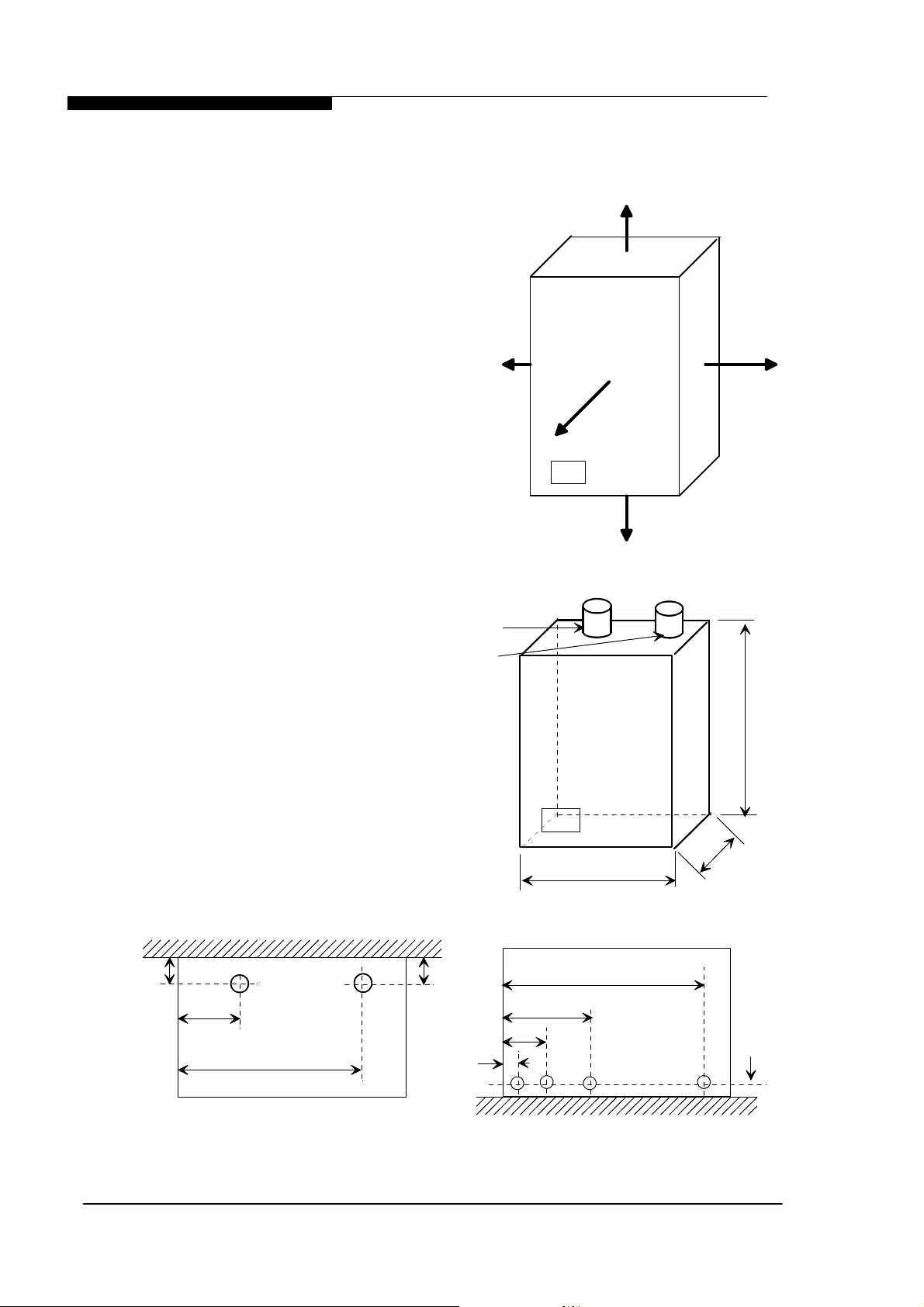
2.1 DIMENSIONS AND MINIMUM
CLEARANCES
The boiler must be installed in minimum
clearances shown to allow subsequent
servicing, and safe operation. However,
larger clearances may be required during
installation.
150
2.2 SERVICE CONNECTIONS
Gas, water, air and flue pipe, condensation,
and electrical connections are as shown.
Gas : 0.75 inch BSP female. Flow/Return 1
inch BSP female.
An optional stand-off frame is also available
which mounts behind the boiler to leave a
50mm deep space behind the boiler. This is
to permit pipe routing behind the boiler if
required. See Section 1.5 - Optional
Accessories.
2.3 POSITION
The C40 and C55 are not suitable for
external installation. The boiler may be
installed in any room or internal space,
although particular attention is drawn
to the requirements of the current IEE
Wiring Regulations and, in Scotland,
the electrical provisions of the Building
Regulations applicable in Scotland,
with respect to the installation of the
boiler in a room or internal space
containing a bath or shower.
Where a room-sealed appliance is
installed in a room containing a bath or
shower, any electrical switch or
appliance control, utilising mains
electricity, should be so situated that it
cannot be touched by a person using
25
Figure 2.1.2
Dimensions
Air Intake
Flue
25
305 (W h en servicing appliance )
10 (W h en appliance is operating )
Figure 2.1.1
150
520
Minimum Clearances
720
0
2
3
Service Connection Locations All dimensions are in mm.
Installation & Servicing Instructions Page : 6
42
65
Top View
Air
447
Flue
51
38
117
Gas
249
Return
Base View
485
Flow
36
Condense
WD265/0/2002 Chapter 2 - Boiler Location The Keston C40, C40P, C55 & C55P
the bath or shower. The C40 and C55 are classified as IP20 (IPX0) and are therefore
suitable for installation in Zone 3 areas, unless subject to hose down.
Compartment installation is permitted - such compartments must be constructed in
accordance with BS 6798.
The wall on which the boiler is mounted must be of suitable load bearing capacity and
must be non-combustible.
The Keston C40 and C55 can be located virtually anywhere desired provided that all
regulations are complied with. Because of the boiler's compact size and venting flexibility,
[NB: Refer to
Section 2.8.3]
the installation is not limited to a boiler room setting. Before locating the boiler near a living
space consider whether the sounds generated by the boiler will be objectionable. The
boiler may be located within a cupboard enclosure to reduce noise levels if located within
a living space. LPG boilers must not be installed in a cellar.
2.4 ELECTRICAL
2.4.1 Electrical Connections
The boiler must be connected to a permanent 230V ~ 50Hz supply, fused at 3A.
The boiler has two thermostats and will therefore accept up to two switched
live signal inputs at 230V, such as heating and hot water demand. For
single signal systems switched live 1 may be used on its own. In the event
the boiler receives a signal from both inputs at the same time the setting of
thermostat 2, usually used for hot water demand, will take priority. Wiring
external to the boiler must be in accordance with current I.E.E wiring regulations
and local regulations.
The method of connection to the mains electricity supply must facilitate complete
electrical isolation of the boiler, preferably by the use of a fused, unswitched three
pin plug and a shuttered socket-outlet, both complying with the requirements of
BS 1363. There must be only one common method of isolation for the boiler and
its control system.
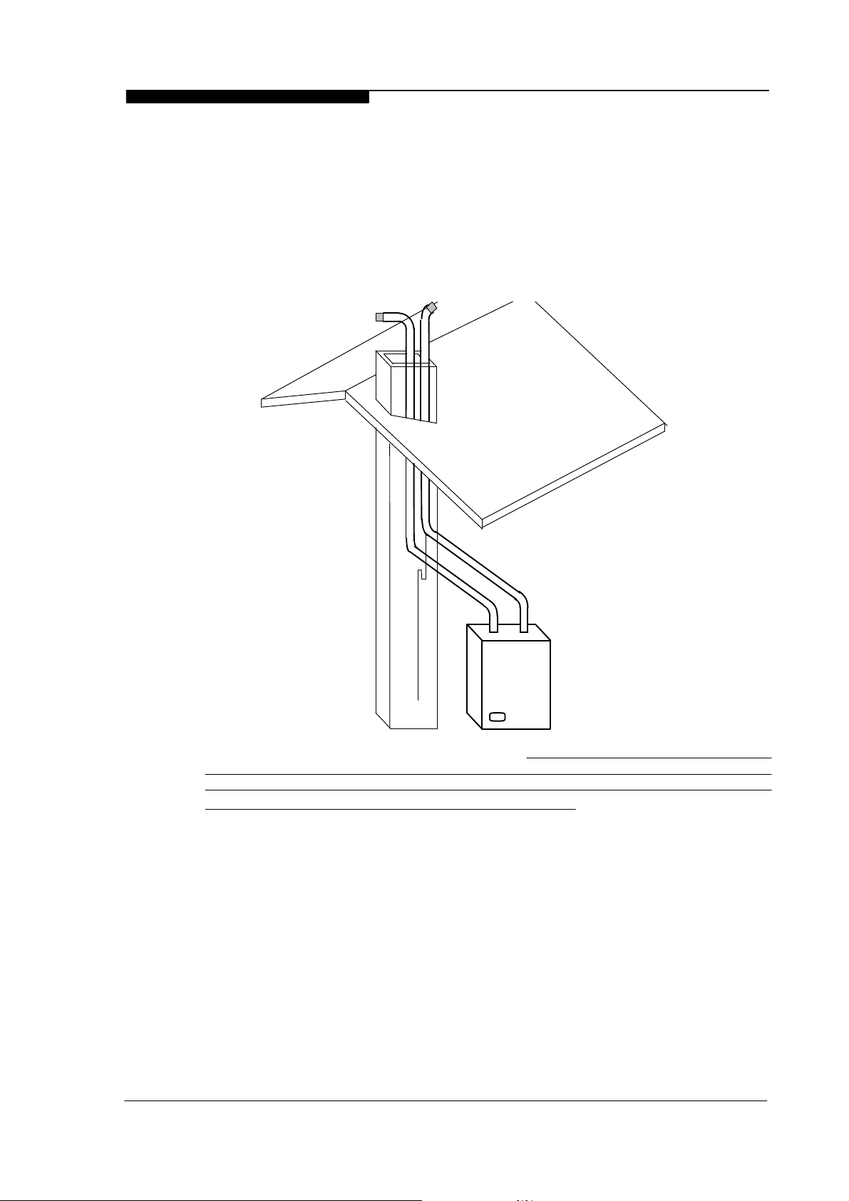
Chimneys not used for
venting any other
appliance may be used.
Secure air & flue pipes at
chimney outlet.
Figure 2.3
Installation & Servicing Instructions Page : 7

WD265/0/2002 Chapter 2 - Boiler Location The Keston C40, C40P, C55 & C55P
The appliance must be connected to the 3A supply via a fused double-pole switch
having at least 3 mm (1/8 inch) contact separation in both poles, serving only the
boiler and the system controls.
The connection point to the mains supply should be readily accessible and
adjacent to the boiler, except for rooms containing a bath or a shower. Refer to
section 2.3 Position.
2.4.2 External Wiring & Controls
1. The boiler is designed so that all control wiring is external to the boiler.
2. A programmer may be used with zone valves to give independent control
of central heating and hot water.
3. A Keston Chronotherm controller may be used to provide room
compensation and optimum stop/start control on heating only systems
4. Control signal inputs must the 230VAC "switched live" type.
5. A Keston outside temperature sensor may be connected as an option.
The boiler will automatically detect this connection and will operate on a
"weather compensation" basis when receiving a signal on switched live 1.
Screened cable (80% density) must be used to connect the outside
temperature sensor.
Brown
V4043H1106
Zone Valve
Heating
V4043H1056
Zone Valve
DHW
2.4.4 Wiring Expample - Honeywell S-Plan for DHW and (Optional) Weather Compensated Heating Control
Blue
Grey
Orange
Green/Yellow
White
Brown
Blue
Grey
Orange
Green/Yellow
5
2
1
9
3
N/U
8
2
1
10
3
Cyl. Thermostat
L641A1039
2.5 BOILER SIZE SELECTION
The C40 and C55 will automatically adjust heat output and pump speed to match the
system requirements at any given time. Efficiency and combustion levels are maintained
at optimum levels throughout the possible output range. The C40 and C55 are therefore
suitable for all systems with a total heat load within the maximum range of the boiler.
2.6 GAS SUPPLY
A gas meter should be connected to the service pipe by the local gas region or their
contractor. An existing meter should be checked preferably by the gas region to ensure
that the meter is adequate to deal with the rate of gas supply required. Installation pipes
should be fitted in accordance with BS 6891.
Minimum/Maximum Gas Pressure:
Natural gas pressure before the gas valve must be maintained at between 18 mbar (7.2 in
WG) and 22 mbar (8.8 in) while the boiler is running.
LPG pressure must be maintained between 31.5 mbar (12.4 in w.g) and 37.6 mbar (14.8
in w.g) while the boiler is running.
Gas pressures above or below these levels will lead to problems associated with the gas
valve's internal pressure regulator.
Supply pipes to the boiler must not be sized less than the boiler inlet connection
(22 mm). Due consideration must be given to the supply pressure to other gas
appliances in the premises. Reduction in dynamic gas supply pressure will result in
intermittent ignition failures. Ensure gas supply pipe work is adequately sized for
Mains Supply
Fused @ 3A
230V
Programmer
ST6300A
L
N
E
SL1
SL2
EX1
EX2
Keston Spa
Cylinder Stat
Keston Spa
Overheat Stat
1
3
2
Live
Neutral
Earth
L
N
1
3
4
C
1
2
1
2
3
1
2
6
4
6
8
Room Thermostat
T6360B1028
KESTON
C55 / C40
OR
C
1
2
C
1
2
4
5
2
1
2
3
9
10
To Keston
Ext. Sensor
[Optional]
6
8
Installation & Servicing Instructions Page : 8
WD265/0/2002 Chapter 2 - Boiler Location The Keston C40, C40P, C55 & C55P
the length of run from the meter to the boiler at a supply rate of 46kW for the C40
and 57kW for the C55 model.
A gas cock is supplied loose with the boiler. This cock should be fitted in the gas line to
the boiler as close to the boiler as possible so that it is easily identified as the cock to
isolate the boiler.
2.7 WATER SYSTEMS
All piping must be installed in accordance with all applicable local and Water Supply
Bylaws for forced hot water heating systems.
Consideration must be given to pipe capabilities and pressure drop through the piping
when selecting pipe sizes. The primary pipe connections to the boiler must be sized
according to the system load, not dictated by the boiler connection sizes.
Water treatment must be carried out to BS 7593 : Treatment of Water in Hot Water
Central Heating Systems.
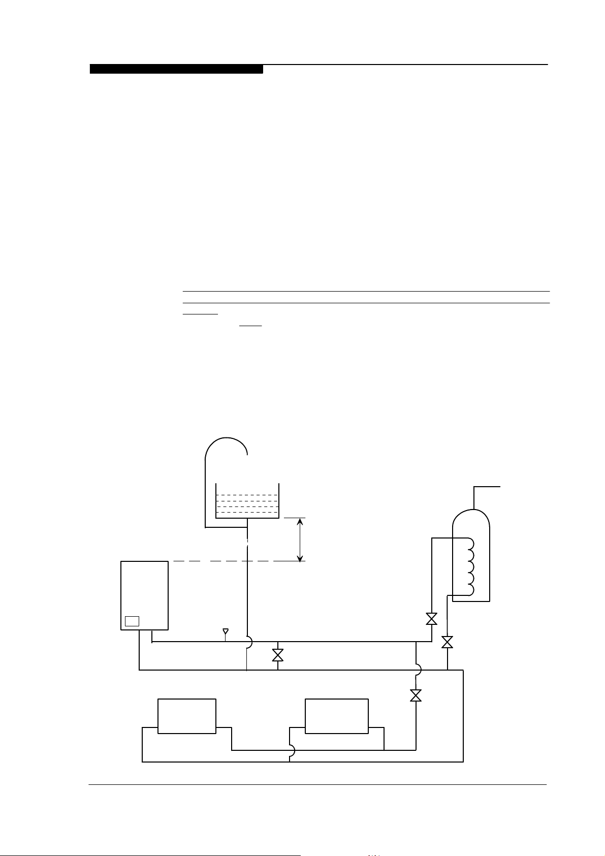
a The C40 and C55 are suitable for use on open, vented water systems with
combined feed and vent fitted to the boiler return.
b It is preferable for use on sealed water systems, provided the appropriate
components required (see Section 2.7.2 Sealed Systems) are included in the
system.
c Any system must be thoroughly flushed clean of grease, dirt and debris, prior to
connection with the boiler. A trap may be installed in the flow line to collect any
solder, or other debris, from the installation.
d All water systems must be constructed to comply with requirements of the Local
Water Authority.
e Always use a system complying with the requirements of BS 5449 and BS 6798.
f System design must ensure an open circuit is always available to ensure
circulation when the pump overrun function is operating after boiler shutdown.
C40
or
C55
Expansion
Pipe
28mm
Safety
Valve
(See note 2.7.1)
FLOW
RETURN
Rad. 2 Rad. 1
Minimum
Expansion
Tank
Minimum
9ft Height
By-pass
Figure2.7.1 : Open Vented System Diagram
Valve
Valve
Cylinder
L/S
Valve
Installation & Servicing Instructions Page : 9

WD265/0/2002 Chapter 2 - Boiler Location The Keston C40, C40P, C55 & C55P
g Copper tubing to BS 2871 Part 1 or barrier plastic pipe suitable to 110 oC, such as
Unipipe, is recommended.
h Jointing should be either with capillary, threaded or compression fittings. Pipes
should have a gradient to ensure air is passed easily to vent points and water
flows readily to drain points.
i Draining taps must be located in accessible positions which permit the draining of
the boiler and hot water storage vessel. Draining taps should be at least 22 mm in
nominal size and be in accordance with BS 2879.
AIR VENT POINTS
j These must be fitted at all high points where air will naturally collect and must be
sited to allow complete draining of the system.
k. Where thermal stores are to be used the thermal store supplier should be
consulted as to the compatibility of the thermal store with a Keston C40 and C55.
Thermal store units where the boiler directly heats an open vented thermal store
are not suitable for use with the C40 or C55.
2.7.1 Open Vented Systems
A typical system is shown in Figure 2.7.1 which includes a combined feed and
vent. Note that the combined feed and vent must be fitted to the primary
RETURN. A safety valve is specified for the primary flow to ensure discharge path
at all times in the event the feed/vent connection is isolated from the boiler flow
[see 2.7.2(i)]. However, in the event the system is configured with no isolation
valve on the primary flow and wired such the boiler cannot fire when all zone
valves are closed, then the safety valve may be omitted. Note that the minimum
static head required is 9 ft at the top of the boiler.
Although suitable for open vented systems with combined feed and vent
arrangements, the C40 and C55 are low water content boilers. As such, any air
entrainment within the system water will produce boiler “kettling”. It is therefore
recommended, if in any doubt, to consider the use of sealed systems where
possible.
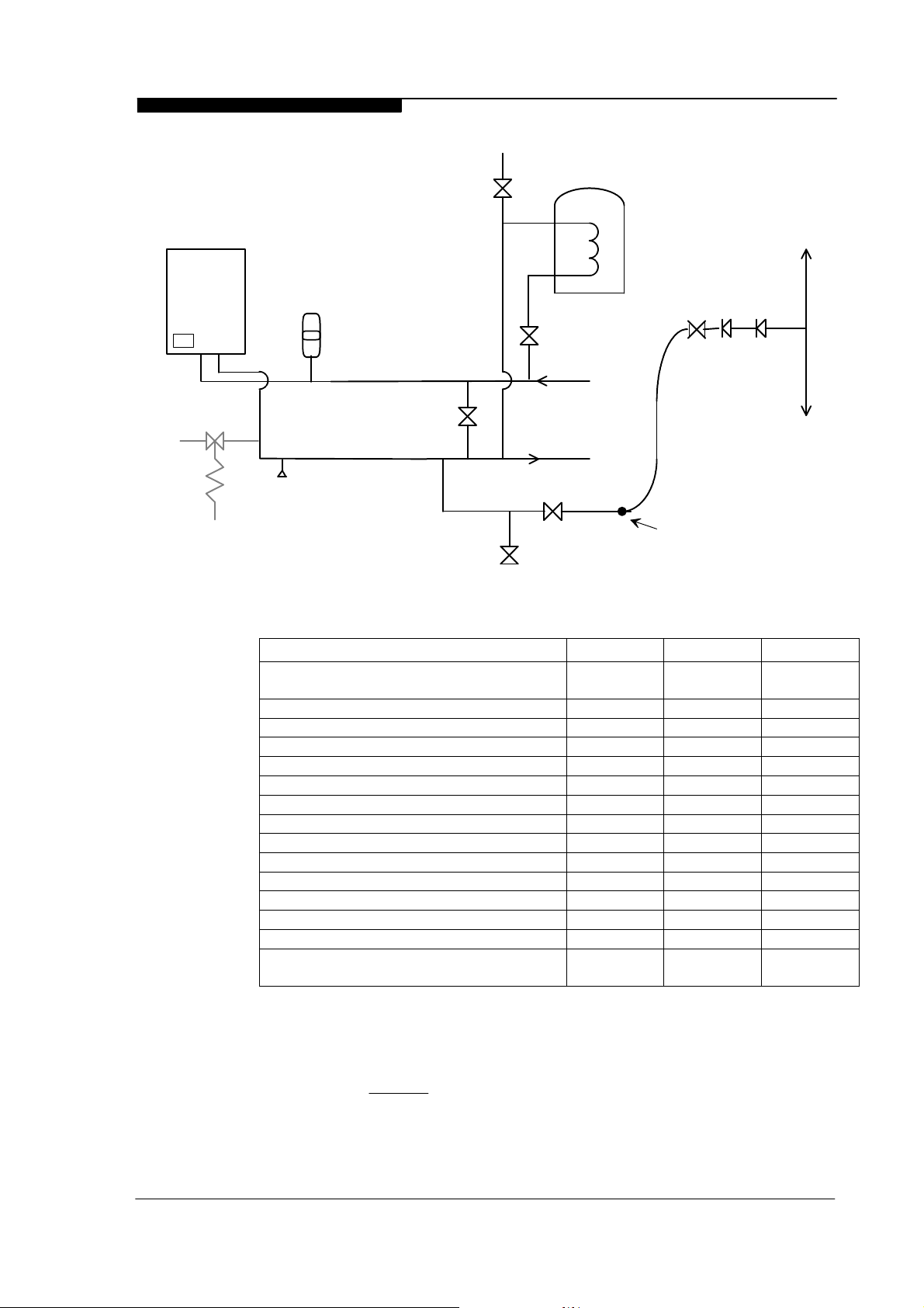
2.7.2 Sealed Systems
Sealed systems must be designed in accordance with BS 5449 and BS 7074 Pt1.
A typical sealed system is shown in Figure 2.7.2. It must include :
(i) A safety valve fitted on the flow, adjacent to the boiler. It must be non
adjustable and preset to 3 bar. A drain pipe must be attached, at least as
big as the valve connection, and routed to drain in any area not
hazardous nor where it may be subject to freezing.
(ii) An expansion vessel complying with BS 4814 and sized in accordance
with the requirements of BS 5449 and BS 7074 Pt 1. The vessel must
be positioned on the primary return to the boiler. Table 2.7.2
Expansion Vessel Selection provides guidance for the correct expansion
vessel size to use.
(iii) A filling point, in accordance with local water authority requirements.
(iv) A method of system make-up (automatic or manual), in accordance with
local water authority requirements.
(v) There must be no permanent connection of mains water to the boiler
system.
(vi) The installation must be designed to work with flow temperatures of up to
110 oC.
All components of the system including the heat exchanger of the indirect cylinder
must be suitable for a working pressure of 3 bar and a temperature of 110 oC.
Care should be taken in making all connections that the risk of leakage is
minimised.
Installation & Servicing Instructions Page : 10
WD265/0/2002 Chapter 2 - Boiler Location The Keston C40, C40P, C55 & C55P
Air Vent
Hose
Union
bib tap
C40
or
C55
Drain
Cock
Expansion
Vessel
By-pass
Bal.
Valve
Safety
Valve
L/S
RETURN
HEATING CIRCUIT
FLOW
Double Check
Valve
Hosepipe
( disconnected
after filling )
Test Cock
Figure 2.7.2 : Sealed System Diagram
Safety Valve Setting
Vessel charge & initial system
pressure.
25 litres
50 litres
75 litres
100 litres
125 litres
150 litres
175 litres
200 litres
225 litres
250 litres
275 litres
300 litres
Multiplying factor for other system
volumes
BS 1010:2
Stop Tap
3.0 bar
Hose
Connector
1.5 bar1.0 bar0.5 bar
VolumeVessel ExpansionTotal Water Content of system
3.92.72.1
7.85.44.2
11.78.26.3
15.610.98.3
19.513.610.4
23.416.312.5
27.319.114.6
31.221.816.7
35.124.518.7
39.027.220.8
42.930.022.9
46.832.725.0
0.1560.1090.0833
Table 2.7.2 Expansion Vessel Selection
2.7.3 Hot Water System (if applicable)
The hot water storage vessel must be of the indirect type (certain direct cylinders
can be used provided they are suitably adapted by fitting an immersion calorifier).
DIRECT CYLINDERS MUST NOT BE USED. Further guidance is provided in BS
1394. It is advisable to fit a locksheild valve on the cylinder return to enable
balancing of the flow rate through the cylinder.
The Keston Spa range of stainless steel unvented cylinders are an ideal
option for use with the Keston range. The Keston Spa range combine
Installation & Servicing Instructions Page : 11
WD265/0/2002 Chapter 2 - Boiler Location The Keston C40, C40P, C55 & C55P
Primary Return
exceptional recovery times with durable, long life stainless steel
construction and all associated controls. Contact Keston Boilers Ltd for
information
2.7.4 Boiler By-pass Piping
Boiler water flows are critical to the operation of the boiler. If flow cannot be
maintained through the system piping to meet the minimums required by the
boiler, insufficient water flows through the boiler will cause the boiler to "kettle" or
even produce steam which can damage the heat exchanger and will invalidate the
heat exchanger warranty. In addition, an open circuit is required after boiler
shutdown to permit circulation during the boilers 2 minute pump overrun
sequence.
It is normally advisable to incorporate a boiler by-pass in the system, especially if
thermostatic radiator valves are used. The flow/return differential should be 10oC
to 20oC. To comply with the new Building Regulations Part L1 the bypass
must of the automatic type.
2.7.5 Balance Headers - Multiple Boiler Installations
Where multiple boilers are installed on a common distribution system
maintenance of balanced flow through each boiler is extremely important. The
implementation of a balance header, as detailed below, is recommended to
ensure adequate and balanced water circulation is maintained by each boilers
integral shunt pump, irrespective of system conditions.
The size of the balance header is dependant on the number of boilers serving the
header. A guide to sizing is given below:
Total Boiler Output (Max) Header Diameter
Up to 110kW 3”
Up to 220kW 4”
Up to 330kW 4.5”
Up to 440kW 5”
When assembling the balance header the following design considerations must
be observed:
A) Each boiler must have its own flow and return connections to the balance
header pipe. Common flow and return connections with the other boilers
will cause reverse circulation effects to occur.
B) The minimum distance between the system flow and return connections
is 600mm.
C) A drain off point should be fitted to the base of the header, along with
cleaning access, for sludge removal.
D) The top of the header should be vented.
2.7.6 Air Elimination
In the initial charge of
water to the boiler
system and in all
subsequent additions of
water to the system
some air will be
dissolved in the water.
As the water is heated
the air is driven out of
the solution and will
collect in high spots in
the system. These air
Expansion
Vessel
C40/C55
Safety
Valve
42mm
Header
AAV
Additional system
pump.
Primary flow
Installation & Servicing Instructions Page : 12
WD265/0/2002 Chapter 2 - Boiler Location The Keston C40, C40P, C55 & C55P
Static Pressure - m WC
Figure 2.8.1 : Terminals
bubbles can interfere with pumping and heat transfer and must be
eliminated.
Installation of air bleed valves at the high spot(s) in the system will allow for air
elimination when filling the system and will allow re-venting in a day or so after all
air has been driven out of solution.
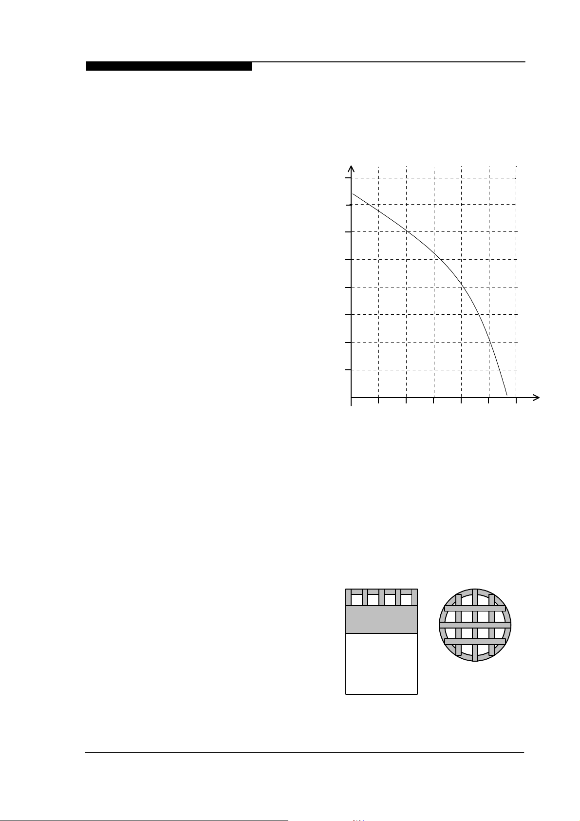
2.7.7 System Pump Selection (if required)
The C40 and C55 feature an
integral circulating pump
8.0
which has sufficient excess
head to drive most domestic
systems. The available head
7.0
is indicated in the chart
below. If the system index
6.0
circuit resistance, at the
desired flow rate, is in excess
of the available head from the
5.0
integral pump an additional
system pump will be required.
4.0
The schematic above
illustrates a recommended
approach to using an
additional system pump. The
additional system pump
should be sized to overcome
the index circuit resistance
only as the boilers integral
pump will overcome boiler
resistance.
If an additional pump is
required the selected pump
must comply with BS 1394.
2.8 FLUE SYSTEM
2.8.1 Design
Individual air supply and flue outlet pipes are used. The material used for flue
outlet &/or air inlet must be muPVC to BS5255 and/or BSEN1566-1 and
BSEN1329 of an internal diameter of 51 mm. (i.e. nominal 50 mm diameter
muPVC solvent weld waste pipe)
Alternatively, where flue or air intake
lengths of up to 45m are require,
Glynwed Friatec DN70 pipe may be
used.
Both 50mm flue outlet terminal and
50mm air inlet terminal are supplied
and are illustrated in Figure 2.8.1.
Both terminals are identical. The
flue and air terminals must be fitted
to the appropriate duct using solvent
weld adhesive. If 75mm terminals
are required these can be obtained
from your Keston Boilers stockist.
Request part numbers
C.17.2.26.00.0 (terminals) and
C.17.2.00.60.0 (50 to 75 adapters).
3.0
2.0
1.0
20 30 40 50 60
10
Water Flow - L/min
Fig 2.7.7 Available Pump Head Graph
Flue Outlet/Air Inlet Terminals
Installation & Servicing Instructions Page : 13
WD265/0/2002 Chapter 2 - Boiler Location The Keston C40, C40P, C55 & C55P
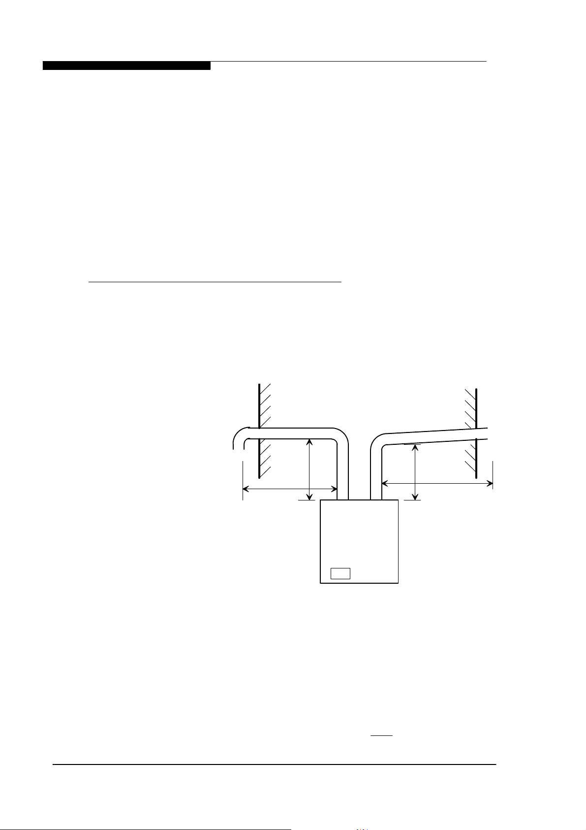
2.8.2 Maximum Lengths
The maximum lengths of both air inlet pipe and flue outlet pipe, when no bends
are used, are as detailed below.
50mm 75mm
Maximum Air Inlet Length : 29.0 m 89.0 m
Maximum Flue Outlet Length : 15.0 m 45.0 m
Maximum Total Flue and Air Intake Length : 30.0 m 90.0 m
However, each bend used has an equivalent length that must be deducted from
the maximum straight length stated above. Knuckle bends must not be used.
A 92.5o sweep elbow is equivalent to 1.0m straight length.
Example (assuming 50mm muPVC flue and air pipework):
Air inlet uses two one 92.5o sweep elbows. Hence, maximum length permissible
(i.e. a+b in figure 2.8.2) = 29.0m - 1.0m - 1.0m = 27.0m
Flue outlet uses one 92.5o sweep elbow. Hence, maximum length permissible (i.e.
c+d in figure 2.8.2) = 15.0m - 1.0 m = 14.0m
2.8.3 Boiler Output vs Flue Length
Due to the
resistance
presented by
extended flue
length a slight
reduction in
maximum boiler
output will occur
where flue
lengths in
excess of 8m
(50mm
muPVC), or
24m (Friaphon
DN70) are
used. In such
cases the boiler
output will be
reduced by 1%
Figure 2.8.2 : Flue & Air Maximum Length Example
per additional
1m (50mm muPVC) and 1% per additional 3m (Friaphon DN70)
2.8.4 Slope
AIR
b
a
C40 or C55
FLUE
d
c
'Horizontal' flue outlet pipework MUST slope at least 3.5 degrees (61 mm per
metre run) downwards towards the boiler where 50mm muPVC pipe is used. In
the event 75mm Friatec pipe wise used a slope of 2 degrees (32mm per metre
run) can be used. Pipework can be vertical. Only swept elbows can be used.
Air inlet pipework can be truly horizontal or vertical, or sloping in a downward
direction towards the boiler but in this case rain, etc., must
be prevented from
Installation & Servicing Instructions Page : 14
 Loading...