

Page 1

WD274/1/2002
Users Instructions For C40,
C40P, C55 and C55P Models
The Gas Safety (Installation And Use) Regulations: 1996 (as amended) impose certain statutory
obligations on gas users. Further information regarding these regulations can be obtained from your
Gas Supplier.
All gas appliances must be installed by competent persons by law in accordance with these
regulations. Membership of CORGI is indication of such a competent person with regard to gas
installation.
It is in your interests, and that of safety, to ensure that the appliance is installed correctly and that the
law is complied with. Failure to do so could lead to a hazardous &/or potentially dangerous situation.
Introduction
These instructions should be carefully read to ensure safe and economical
use of your boiler.
The Keston C40 and C55 are high efficiency central heating condensing
boilers designed to provide central heating and indirect sanitary hot water
supply. They are designed for use with fully pumped systems only. The C40
and C55 models are supplied for natural gas use only. The C40P and C55P
models are supplied for LPG only.
Servicing
To ensure continual safe and efficient operation of the boiler it is
recommended that the appliance be checked and serviced as necessary at
regular intervals. Generally once per year will be sufficient. It is the law that
any servicing must be carried out by a competent person.
NB: There are no user serviceable parts inside the boiler cabinet. The
cabinet should only be removed by a qualified competent person.
Clearances
If fixtures are to positioned close to the boiler the following minimum
clearances must be observed: Top : 150 mm, Bottom : 150 mm, Left : 25 mm, Right :
25 mm & Front : 305 mm. Extended clearance is required to the front to allow for
access for servicing.
page i
Page 2
WD274/1/2002
Cleaning
Normal casing cleaning only requires dusting with a dry cloth. To remove
more stubborn marks wipe with a damp cloth and finish with a dry cloth.
Boiler Setup
1) Check that the gas
supply from the gas
meter is turned ON
2) Switch on the
electric supply to
the boiler and
controls and set the
heating controls to
call for heat.
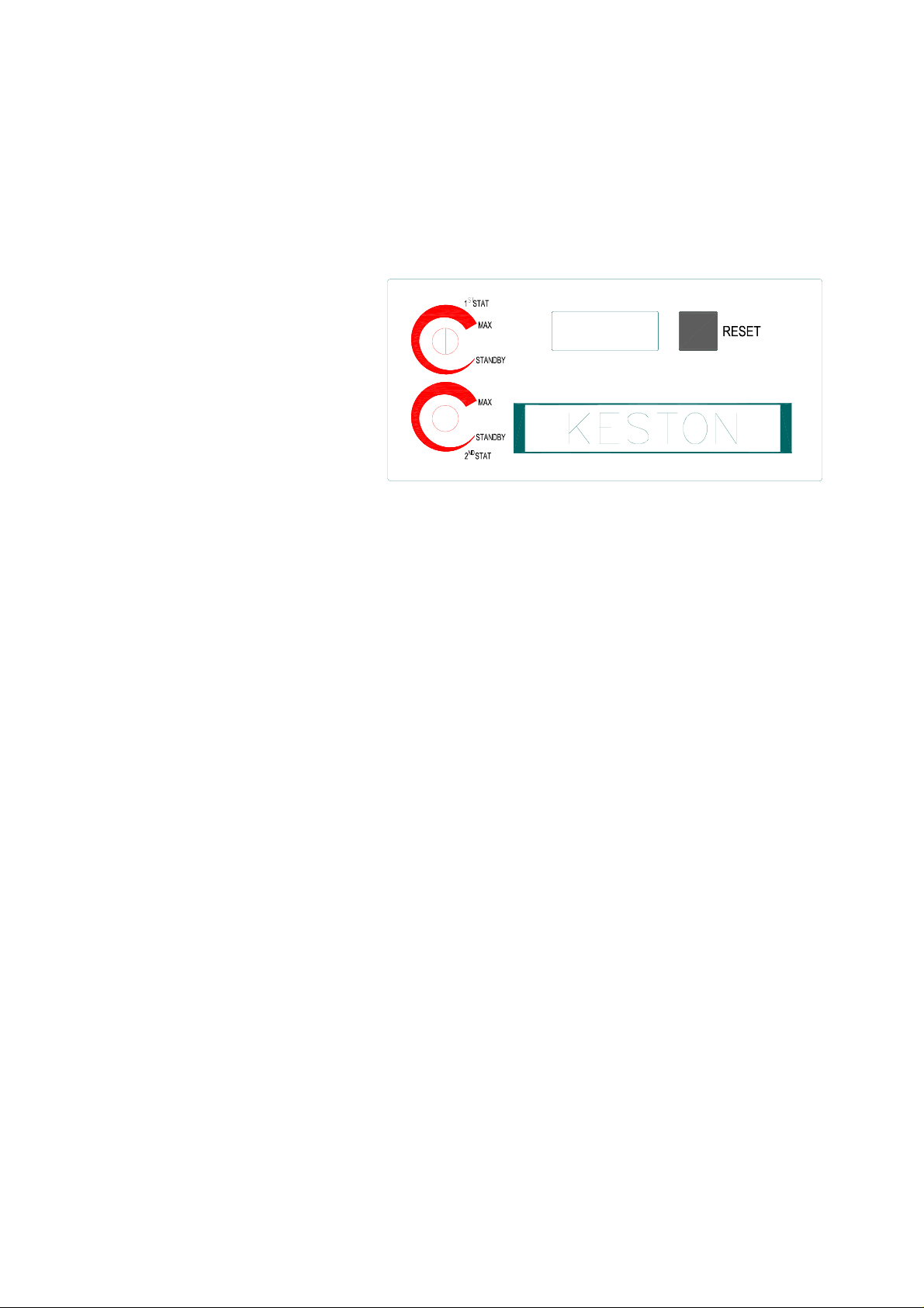
To Light The Boiler
The C40 and C55 boilers
incorporate dual thermostats to allow two different zones to be connected to operate
at two different temperatures. Generally the central heating zone is connected to
zone 1 and the hot water cylinder to zone 2. You should ask your installer to advise
whether your boiler serves one or two zones.
To set thermostat temperatures you must turn the relevant knob to the required
position. As you turn the knob the display will change to either “c nn” or “d nn”,
depending on the knob being turned. As the knob is turned the required temperature
(the last two digits of the display) change. Set the knob to the position which gives
the required temperature. When the knob is release the display, after a few seconds,
will return to normal.
If the boiler detects whether zone requires heat the following sequence will occur:
1) The fan and pump will start inside the boiler and the display will indicate “1 nn”
to show the boiler has started the first stage of the ignition sequence.
2) After 5 seconds the display will change to “2 nn” to indicate the spark ignition
of the sequence has started.
3) After 3 seconds the display will change to “3 nn” for zone 1 and “4 nn” for
zone 2, to show the boiler is now alight.
4) The boiler will adjust the output to best match the demands of the system.
The last two digits of the display will continuously show the boiler
temperature. The boiler control will allow the temperature to overshoot the
setting by up to 5 degrees before shutting down. The standard display codes
are as follows:
0 nn Boiler in standby as no heat request from either zone 1 nn
Boiler commencing ignition sequence
2 nn Boiler generating spark ignition
page ii
Page 3

WD274/1/2002
3 nn Boiler burning for zone 1
4 nn Boiler burning for zone 2
5 nn Temporary mode whilst boiler adjusts its internal settings
6 nn Burner off because required temperature has been reached
7 nn Boiler at end of heat request from zone 1
8 nn Boiler at end of heat request from zone 2
A nn Temporary mode whilst boiler adjusts its internal settings
9 nn Boiler off due to unexpected problem. The boiler will attempt to
re-fire from this mode. In this mode the display will alternately
flash “9 nn” and “b xx” where the “xx” has the following meaning:
O
b 18 Boiler ran too hot, > 95
b 19 Boiler ran too hot, > 95
C flow temperature
O
C return temperature
b 24 Boiler circulating in reverse. Check external pump
b 25 Boiler rising in temperature too quickly. Check for system
blockages
b 26 Low water pressure. Top up system pressure and check
for leaks.
b 28 No signal from fan, possible stuck fan motor.
b 29 Fan running when not required.
b 30 Circulation too slow. Check system for blockages
b 65 Waiting for fan to start. Possibly stuck.
All of the above displays, up to “A nn” indicate normal boiler operation. Display “9 nn”
indicates a delay in boiler operation but will not stop boiler operation.
Precautions
Care must be taken at all times to ensure that no blockage or obstruction is present
in the condensate drainage line. In addition the air intake and flue exhaust terminals
of the appliance must be free of obstruction at all times.
Frost Protection
The C40 and C55 have an integral frost protection thermostat. However, care should
also be taken to ensure that any exposed pipework is adequately insulated to
prevent freezing.
Error Codes
In the event of a fault causing a boiler shutdown the display will show an error
message “E nn”.
Description of faultDisplay
Flame detected when not expected. Check boiler earth and probe condition.E 00
E 02
No ignition after restart. Check gas supply, gas valve operation and ignitor electrode
spark generation
Gas valve faulty or not connectedE 03
Power has been reset whilst boiler was in lockoutE 04
Internal electronics error - rest or replace control boxE 11
page iii
Page 4

Fl
E 18
WD274/1/2002
ow overheat - check water circulation
Maximum return temperature exceeded. Check circulation.E 19
Flow temperature increased too quickly. Check water circulation.E 25
Difference between flow and return temperatures too high. Check circulation.E 30
Flow thermistor short circuit - check/replace connections/thermistorE 31
Return thermistor short circuit - check/replace connections/thermistorE 32
Flow thermistor open circuit - check/replace connections/thermistorE 36
Return thermistor open circuit - check/replace connections/thermistorE 37
Low water pressureE 44
Gas Leak or Fault
If you suspect a gas leak turn off the appliance
immediately, turn off the gas tap to the appliance
and contact your local gas region without delay.
If you suspect a fault with the appliance it must not be used until the fault has
been corrected by a competent person.
In the unlikely event of a breakdown consult your Installer or Service Engineer and
advise the fault display and description of fault.
BENCHMARK INITIATIVE
As part of the industry wide “Benchmark” Initiative all C40 and C55 boilers now include a Benchmark
Installation, Commissioning and Service Record Log Book. This log book should be completed by
your installer at the end of the installation and commissioning process. The details of the Log Book
will be required in the event of and warranty work being required. There is also a section to be
completed after each regular service visit.
This log book should be kept in a safe place for the life of the boiler.
The boiler should be installed and serviced only by CORGI registered operatives. All CORGI
registered Installers carry a CORGI ID card, and have a registration number. Both should be
recorded in your Benchmark Log Book. You can check your installer by calling CORGI direct on
01256 372300.
page iv
 Loading...