


MAT 6V
Table of contents
 Loading...
MODEL
INSTRUCTION MANUAL
IMPORTANT NOTES:
1) This manual is valid for the following Model and associated serial numbers:
MODEL SERIAL NO. REV. NO.
2) A Change Page may be included at the end of the manual. All applicable changes and
revision number changes are documented with reference to the equipment serial num-
bers. Before using this Instruction Manual, check your equipment serial number to identify
your model. If in doubt, contact your nearest Kepco Representative, or the Kepco Docu-
mentation Office in New York, (718) 461-7000, requesting the correct revision for your par-
ticular model and serial number.
3) The contents of this manual are protected by copyright. Reproduction of any part can be
made only with the specific written permission of Kepco, Inc.
Data subject to change without notice.
KEPCO
®
THE POWER SUPPLIER™
ORDER NO. REV. NO.
KEPCO, INC.
l
131-38 SANFORD AVENUE
l
FLUSHING, NY. 11352 U.S.A.
l
TEL (718) 461-7000
l
FAX (718) 767-1102
email: hq@kepcopower.com
l
World Wide Web: http://www.kepcopower.com
KEPCO INC.
An ISO 9001 Company.
ATE 100-0.5M F19688 9
©2007, KEPCO, INC.
MAT FULL RACK
POWER SUPPLY
6V, 15V, 25V AND 36V MODELS
MAT FULL RACK
POWER SUPPLY
NOTE This on-line version of the Technical
Manual includes only installation and
operating instructions. For the complete
manual, please contact Kepco.


228-1348 DC-COMP/INST 052704
A
Declaration of Conformity
Application of Council directives:
73/23/EEC (LVD)
93/68/EEC (CE mark)
Standard to which Conformity is declared:
EN61010-1:2001 (Safety requirements for electrical equipment for measurement,
control and laboratory use - Part 1)
Manufacturer's Name and Address:
KEPCO INC.
131-38 SANFORD AVENUE
FLUSHING, N.Y. 11352 USA
Importer's Name and Address:
Type of Equi pme nt:
Component Power Supply
Model No.:
[PRODUCT MODEL NUMBER]
Year of Manufact ure:
I, the undersigned, declare that the product specified above, when used in conjunction with the condi-
tions of conformance set forth in the product instruction manual, complies with the requirements of the
Low Voltage Directive 73/23/EEC, which forms the basis for application of the CE Mark to this product.
Place: KEPCO Inc.
131-38 Sanford Ave.
Flushing, N.Y.11352 USA
Date:
Saul Kupferberg
(Full Name)
VP OF SALES
(position)
R
E
P
R
E
S
E
N
T
A
T
I
V
E
C
O
P
Y

B
228-1351 COND/CONFORM 052704
Conditions of Conformance
When this product is used in applications governed by the requirements of the EEC, the following restric-
tions and conditions apply:
1. For European applications, requiring compliance to the Low Voltage Directive, 73/23/EEC, this power
supply is considered a component product, designed for "built in“ applications. Because it is incom-
plete in construction, the end product enclosure must provide for compliance to any remaining electri-
cal safety requirements and act as a fire enclosure. (EN61010-1:2001, Cl. 6, Cl. 7, Cl.8, and Cl. 9)
2. This power supply is designed for stationary installation, with mains power applied via a detachable
power supply cord or via direct wirin g to the source powe r term inal bloc k.
3. This power supply is considered a Class 1 (earthed) product. It is intended for use as part of equip-
ment meant for test, measurement and laboratory use, and is designed to operate from single phase,
three wire power systems. This equipment must be installed within a suitably wired equipment rack,
utilizing a three wire (grounded) mains connection. See wiring section of this manual for complete
electrical wiring instruct ion s. (EN61 010 -1:200 1, C l.6.10.1 )
4. This power supply has secondary output circuits that are considered hazardous, and which exceed
240 VA at a potential of 2V or more.
5. The output wiring terminals of this power supply has not been evaluated for field wiring and, therefore,
must be properly configured by the end product manufacturer prior to use.
6. This power supply employs a supplementary circuit protector in the form of a circuit breaker mounted
on the front panel. This circuit breaker protects the power supply itself from damage in the event of a
fault condition. For complete circuit protection of the end product, as well as the building wiring, it is
required that a primary circuit protection device be fitted to the branch circuit wiring. (EN61010-
1:2001, Cl. 9.5)
7. Hazardous voltages are present within this power supply during normal operation. All operator adjust-
ments to the product are made via externally accessible switches, controls and signal lines as speci-
fied within the product operating instructions. There are no user or operator serviceable parts within
the product enclosure. Refer all servicing to qualified and trained Kepco service technicians.
228-1352 SAFETY - (COVER REMOVAL) 022300 C/(D BLANK)
SAFETY INSTRUCTIONS
1. Installation, Operation and Service Precautions
This product is designed for use in accordance with EN 61010-1 and UL 3101 for Installation Category 2,
Pollution Degree 2. Hazardous voltages are present within this product during normal operation. The
product should never be operated with the cover removed unless equivalent protection of the operator
from accidental contact with hazardous internal voltages is provided:
2. Grounding
This product is a Class 1 device which utilizes protective earthing to ensure operator safety.
3. Electric Shock Hazards
This product outputs hazardous voltage and energy levels as a function of normal operation. Operators
must be trained in its use and exercise caution as well as common sense during use to prevent accidental
shock.
There are no operator serviceable parts or adjustments within the product enclosure.
Refer all servicing to trained service technician.
Source power must be removed from the product prior to performing any servicing.
This product is factory-wired for the nominal a-c mains voltage indicated on the rat-
ing nameplate located adjacent to the source power connection on the product's rear
panel. To reconfigure the product input for other nominal mains voltages as listed
herein, the product must be modified by a trained service technician.
The PROTECTIVE EARTHING CONDUCTOR TERMINAL must be properly con-
nected prior to application of source power to the product (see instructions on instal-
lation herein) in order to ensure safety from electric shock.
PROTECTIVE EARTHING CONDUCTOR TERMINAL - This symbol indicates the
point on the product to which the protective earthing conductor must be attached.
EARTH (GROUND) TERMINAL - This symbol is used to indicate a point which is
connected to the PROTECTIVE EARTHING TERMINAL. The component installer/
assembler must ensure that this point is connected to the PROTECTIVE EARTH-
ING TERMINAL.
CHASSIS TERMINAL -This symbol indicates frame (chassis) connection, which is
supplied as a point of convenience for performance purposes (see instructions on
grounding herein). This is not to be confused with the protective earthing point, and
may not be used in place of it.
This symbol appears adjacent to any external terminals at which hazardous voltage
levels as high as 500V d-c may exist in the course of normal or single fault condi-
tions.
This symbol appears adjacent to any external terminals at which hazardous voltage
levels in excess of 500V d-c may exist in the course of normal or single fault condi-
tions.
!
!
!
!
!

MAT FULL RACK/ 022300
i
TABLE OF CONTENTS
SECTION PAGE
SECTION 1 - INTRODUCTION
1.1 Scope Of Manual..................................................................................................................................... 1-1
1.2 General Description................................................................................................................................. 1-1
1.3 Specifications, Electrical.......................................................................................................................... 1-3
1.4 DC Output Ratings For 1/3, 2/3 And Full Rack Modules....................................................................... 1-4
1.5 Miscellaneous Features ......................................................................................................................... 1-8
1.6 Accessories ............................................................................................................................................. 1-8
1.7 Safety ...................................................................................................................................................... 1-9
SECTION 2 - INSTALLATION
2.1 Unpacking And Inspection....................................................................................................................... 2-1
2.2 Terminations............................................................................................................................................ 2-1
2.3 AC Input Requirement............................................................................................................................. 2-4
2.4 Cooling .................................................................................................................................................... 2-5
2.5 Installation ............................................................................................................................................... 2-5
2.6 Grounding................................................................................................................................................ 2-5
2.6.1 Safety Grounding............................................................................................................................... 2-5
2.6.2 DC (Output) Grounding...................................................................................................................... 2-6
2.6.3 Power Module To Load Interface..................................................................................................... 2-6
2.6.4 Load Connection, Local Error Sensing .............................................................................................. 2-8
2.6.5 Load Connection With Remote Error Sensing................................................................................... 2-8
2.7 Operating Configuration .......................................................................................................................... 2-9
2.8 Preliminary Check-out ............................................................................................................................ 2-9
2.8.1 Example 1: Full Scale Voltage Check................................................................................................ 2-10
2.8.2 Example 2: Full Scale Current Check:.............................................................................................. 2-11
2.8.3 Example 3: To Reset the Power Module ........................................................................................... 2-12
SECTION 3 - OPERATION
3.1 General.................................................................................................................................................... 3-1
3.2 Introduction To Controlling The MAT Power Module Output................................................................... 3-1
3.2.1 MAT/Power Module Controller System.............................................................................................. 3-3
3.2.2 MAT/TMA Pc-27 System ................................................................................................................... 3-3
3.3 Automatic (Tracking) Control Of The Crowbar Level............................................................................... 3-4
3.4 Power Module Controller/MAT Time Delays (To Obtain A Valid Status):................................................ 3-4
3.5 Power Loss Circuit .................................................................................................................................. 3-4
3.6 Remote Programming ............................................................................................................................. 3-5
3.6.1 General.............................................................................................................................................. 3-5
3.6.2 SCPI Programming............................................................................................................................ 3-6
3.6.2.1 SCPI Program Example............................................................................................................... 3-6
3.6.3 CIIL Programming.............................................................................................................................. 3-8
3.6.3.1 Examples Using CIIl To Program The MAT Power Module......................................................... 3-8
3.6.3.1.1 Example 1: Program Positive Voltage With Current Limit......................................................3-8
3.6.3.1.2 Example 2 : Program Negative Voltage With Current Limit ...................................................3-10
3.6.3.1.3 Example 3: Program Current And Voltage Limit .....................................................................3-11
APPENDIX A - CIIL COMMAND DEFINITIONS

LIST OF FIGURES
FIGURE TITLE PAGE
ii
MAT FULLRACK 022300
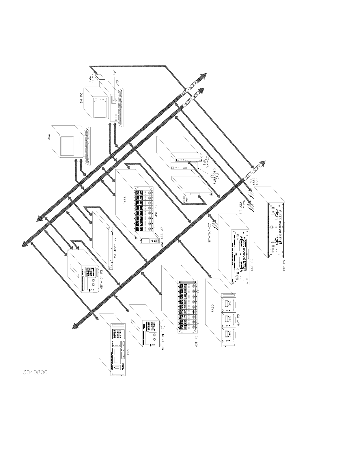
1-1 Remotely Controlled Power Supply Configurations Using Kepco Products............................................... 1-2
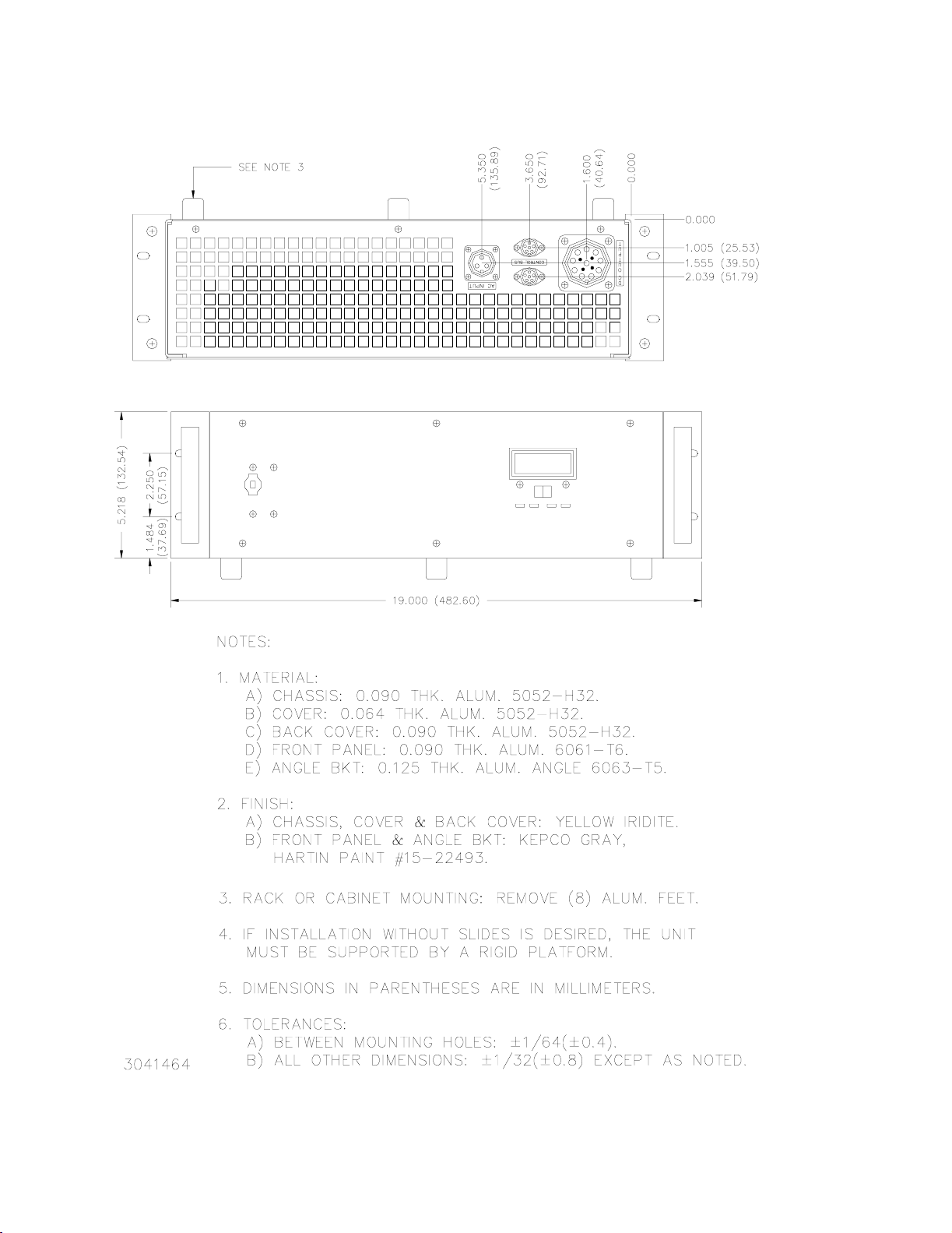
1-2 MAT Power Module Mechanical Outline Drawing...................................................................................... 1-6
1-3 The TMA 4882-27 Controller And MAT Power Modules ............................................................................ 1-9
2-1 Front View Of The Full Rack MAT Power Supply ...................................................................................... 2-2
2-2 Rear View Of The MAT Full Rack Power Module ...................................................................................... 2-3
2-3 MAT Module Barrier Strip With Jumpers For 115 Or 230 Va-c ............................................................... 2-5
2-4 Variation Of Output Impedance With Frequency For A Voltage Source And A Current Source................ 2-7
2-5 Load Connections, Local Sensing.............................................................................................................. 2-8
2-6 Load Connections, Remote Sensing.......................................................................................................... 2-8
3-1 Top Cover Access Points........................................................................................................................... 3-1
3-2 MAT Power Module Control Section (Top Cover Removed)...................................................................... 3-5
3-3 Tree Diagram of SCPI Commands Used with MAT Power Supplies ......................................................... 3-6
3-4 Typical Example Of MAT Power Supply Program Using SCPI Commands............................................... 3-7
A-1 FNC — Function Command ....................................................................................................................... A-1
A-2 INX — Initiate Op Code Command ............................................................................................................ A-2
A-3 FTH — Fetch Command ............................................................................................................................ A-2
A-4 SET Command........................................................................................................................................... A-3
A-5 OPN, CLS — Open, Close Relay Commands ........................................................................................... A-4
A-6 RST — Reset Command............................................................................................................................ A-4
A-7 CNF, IST — Confidence Test, Internal Self Test Commands .................................................................... A-4
A-8 STA — Status Command........................................................................................................................... A-5

MAT 36-30 022300
iii/(vi Blank)
LIST OF TABLES
TABLE TITLE PAGE
1-1 MAT Power Module Features And Specifications .......................................................................................1-3
1-2 MAT Power Modules Power Output Ratings ...............................................................................................1-5
1-3 Safety Symbols ...........................................................................................................................................1-9
2-1 Internal Controls Accessible Through Top Cover .......................................................................................2-1
2-2 Front Control MAT Power Module ..............................................................................................................2-2
2-3 Rear Terminations, MAT Power Module .....................................................................................................2-3
2-4 DC Output Connector Pin Functions ...........................................................................................................2-3
2-5 Input And Output Connectors .....................................................................................................................2-4
2-6 Internal Jumper Configuration .....................................................................................................................2-9
3-1 Device Address Selection For The MAT power Module .............................................................................3-2
A-1 CIIL Subsystem Command/query Index .................................................................................................... A-1
A-2 CIIL Error Messages .................................................................................................................................. A-5

MAT FULL RACK 022300
1-1
SECTION 1 - INTRODUCTION
1.1 SCOPE OF MANUAL
This manual contains instructions for the installation, operation, and maintenance of the Full
Rack size MAT series of voltage and current stabilized DC Power Modules manufactured by
Kepco, Inc. Flushing, New York, U.S.A.
1.2 GENERAL DESCRIPTION
The Kepco MAT Power Module with overvoltage, overcurrent, overtemperature, polarity rever-
sal, and power loss protection is a digitally controlled precision stabilized Power Module that
delivers either stabilized voltage or current. A single front panel meter with a selector switch
constantly monitors the output voltage or the output current. The prevailing operating mode is
indicated by LED mode indicators on the front panel. Operating mode crossover is dependent
on commands from a Host Computer and the value of the load. The Power Module has a linear
and fully dissipative NPN pass transistor driven by high gain integrated circuit amplifiers. The
output of the Power Module is fully programmable
The Power Module features full range output control by means of a compatible Kepco Power
Module Controller. Control of the MAT Power Module is via the IEEE 1118 2-wire serial bus
operating at 375KHz; as many as 27 separate modules of either the MAT, MST, MBT or BOP
Series design can be addressed via the bus (see Figure 1-1). Decoders for RS232, IEEE-488
and VXI are available in modular form and stand-alone types. As shown in Figure 1-1, the fol-
lowing controllers are available to control of MAT Power Modules directly from a computer.
a. Controller Model TMA PC-27 plugs into a half-card slot of a DOS-based PC and allows key-
board control of the MAT via the IEEE 1118 bus.
b. Controller Model TMA 4882-27 is free-standing and allows host computers designed for
RS232 or IEEE 488 bus communication to control the MAT via the IEEE 1118 bus.
c. Controller Model TMA-VXI-27 plugs into a slot in a VXI chassis and allows VXI-based com-
puters to control the MAT via the IEEE 1118 bus.
d. Controller Model MST 488-27 plugs into a slot in a Model RA 55 Rack Adapter and allows
host computers designed for RS232 or IEEE 488 bus communication to control the MAT via
the IEEE 1118 bus.
e. The MAT Power Module can also be directly controlled via the keypad of the MBT Series
(“G” Option) Power Supply via the IEEE 1118 bus.
An important feature of the MAT Series Power Module is the overvoltage and overcurrent pro-
tection circuits. This protection is provided by two autotracking amplifiers that have an overvolt-
age and overcurrent tracking range of 10% ± 3% of the nominal values above the programmed
Power Module output voltage or current (e.g., for 55V MAT which has been programmed to 2V,
the overvoltage will trip at 7.5 V (5.5V, 10% of nominal + 2V, programmed).
The MAT series Power Modules are built in several mechanical sizes according to their approx-
imate output power rating 1/3 Rack, 2/3 Rack and Full Rack (see Mechanical Outline Drawing of
the Power Module Chassis, Figure 1-2).
Power transistors and drivers on all Power Module designs are mounted on highly efficient pat-
ented heat sink assemblies that are cooled by fans.
MAT 1/3 and 2/3 Rack size modules are designed to operate in either one of two housings
called RA 50 and RA 51. RA 50 is 5-1/4" x 19" x 25" and accepts up to three 1/3 Rack Power
Modules. RA 51 is similarly sized, but configured for one 1/3 Rack Module and one 2/3 Rack
Module. Full Rack MAT Power Modules mount directly into a standard 19 inch Equipment Rack.
1-2
MAT FULL RACK 022300
FIGURE 1-1. REMOTELY CONTROLLED POWER SUPPLY CONFIGURATIONS USING KEPCO PRODUCTS
3040800

MAT FULL RACK 022602
1-3
1.3 SPECIFICATIONS, ELECTRICAL
a) MAT Power Module Features And Specification
TABLE 1-1. MAT POWER MODULE FEATURES AND SPECIFICATIONS
PARAMETER CONDITION
MAT POWER MODULE
1/3 RACK 2/3 RACK FULL RACK
Input Voltage Range
USER
SELECTABLE
105-125 VAC
210-250 VAC
Input Current Max
115 VAC 7.0A 14.0A 21.0A
230 VAC 3.5A 7.0A 10.5A
Input Frequency RANGE 47-63 Hz
Voltage/Current Adjust-
ment Range
RANGES
0 to 100% of rating, by preprogrammed setting,
within inherent resolution limits
Programming
Resolution
Voltage 0.024% Eo max (12 bits)
Current 0.024% Io max (12 bits)
Programming Accuracy
Voltage 0.024% Eo max
Current 0.1% Io max
Data Read Back
Accuracy via Digital Bus
Volt ag e 0.1% Eo m ax
Current 0.12% Io max
Source Effect
Voltage 0.001% Eo max
Current 0.005% Io max
Load Effect
Voltage 0.002% Eo max
Current 0.024% Io max or 4 mA (whichever is greater)
Time 8 Hour Drift
Voltage 0.01% Eo max
Current 0.02% Io max
Temperature
Coefficient/°C
Voltage 0.01% Eo max
Current 0.02% Io max
Ripple & Noise
Volt ag e
rms: 0.001% Eo max or 0.3 mV (whichever is greater)
p-p: 0.01% Eo max or 3 mV (whichever is greater)
Current
rms: 0.03% Io max
p-p: 0.3% Io max
Transient Recovery Voltage
150
µ
sec to recover within 0.1% Eo max for 10% to 100%
step in rated load current
Temperature
Operating 0 to 50 °C
Storage -20 to +70 °C
Cooling Built-in fan, air exhaust to rear
Remote Sensing Range 0.5 volts per lead (Provision for 4-terminal connection to load)
DC Output Isolation Voltage 500 Vdc
Leakage Current Output to chassis 5
µ
A rms or 50
µ
A p-p @ 115V a-c
Series/Parallel Operation Consult Kepco application engineering
Output Display
3-1/2 digit LCD
Panel Meter
Switch selectable voltage/current
IndIcators 4 LEDs
Voltage and Current Mode,Output Enabled, Polarity
Reversed
Output Enable/Disable
Built in power and sensing relays controlled through IEEE
1118 b us
Polarity Reversal
Built in power and sensing relays controlled through IEEE
1118 b us

1-4
MAT FULL RACK 022300
1.4 DC OUTPUT RATINGS FOR 1/3, 2/3 AND FULL RACK MODULES
a) MAT Power Module DC Output Ratings 1/3, 2/3, and Full Rack Size - see Table 1-2
b) Output range:
1) Voltage mode: 0-100% of rated voltage
2) Current mode: 0-100% of rated current
Protection
Overvoltage Tracks program voltage, Crowbars output and turns off input
Overcurrent Tracks program current, Crowbars output and turns off input
Overtemperature
Monitors heat sink temperature, Crowbars output and turns
off input
Polarity Reversal Built in diodes protect unipolar supply output
Power Loss Detects loss of ac input power, disables output
Source Connections
3-wire power entry, via user-configurable mating connector
(supplied) and proper gage wires (not supplied)
Load Connections
5-wire connection, via user-configurable mating connector
(supplied) and proper gage wires (not supplied)
DC Power Output: 2 wires
Output Sense Terminals: 2 wires
Ground: 1 wire
Remote Control
Signal Connections
Two 2-wire connections via user-configurable mating
connector supplied and 22 AWG wire (not supplied).
Connectors in parallel for daisy chaining multiple power
supplies (full rack only).
Dimensions See Figure 1-2.
Weight LBS336075
Mounting Front
Three 1/3 rack
modules plug into
RA 50. One 1/3
and one 2/3 rack
modules plug into
RA 51
One 1/3 and one
2/3 rack modules
plug into RA 51
Full Rack mounts
directly into 19
inch Rack
Filler Panels
For either RA 50
or RA 51
RFP 50-1: 1/3 Panel
RFP 50-2: 2/3 Panel.
TABLE 1-1. MAT POWER MODULE FEATURES AND SPECIFICATIONS (CONTINUED)
PARAMETER CONDITION
MAT POWER MODULE
1/3 RACK 2/3 RACK FULL RACK

MAT FULL RACK 022300
1-5
TABLE 1-2. MAT POWER MODULES POWER OUTPUT RATINGS
MODEL VOLTS
(Range)
AMPS
Range
POWER
(Nominal)
360W MODULES-1/3 RACK SIZE-DC OUTPUT RATINGS
MAT 6-32 0-6 0-32 192
MAT 15-20 0-15 0-20 300
MAT25-14 0-25 0-14 350
MAT 36-10 0-36 0-10 360
MAT 55-7 0-55 0-7 385
MAT 75-5 0-75 0-5 375
MAT 100-3.6 0-100 0-3.6 360
MAT 150-2.4 0-150 0-2.4 360
720W MODULES-2/3 RACK-DC OUTPUT RATINGS
MAT 6-64 0-6 0-64 384
MAT 15-40 0-15 0-40 600
MAT25-28 0-25 0-28 700
MAT 36-20 0-36 0-20 720
MAT 55-14 0-55 0-14 770
MAT 75-10 0-75 0-10 750
MAT 100-7.2 0-100 0-7.2 720
MAT 150-4.8 0-150 0-150 720
1080W MODULES-FULL RACK-DC OUTPUT RATINGS
MAT 6-100 0-6 0-100 600
MAT 15-60 0-15 0-60 900
MAT 25-42 0-25 0-42 1050
MAT 36-30 0-36 0-30 1080
MAT 55-20 0-55 0-20 1100
MAT 75-15 0-75 0-15 1125
MAT 100-10 0-100 0-10 1000
MAT 150-7 0-150 0-7 1050
1-6
MAT FULL RACK 022300
FIGURE 1-2. MAT POWER MODULE MECHANICAL OUTLINE DRAWING (SHEET 1 OF 2)
Loading...