


Kit 219-0550
Table of contents
 Loading...
INSTRUCTION MANUAL
KEPCO
An ISO 9001 Company.
BOP 1000W
Transition Circuit
KIT 219-0550
BOP 10-75MG
TRANSITION CIRCUIT KIT
1. DESCRIPTION
Kepco KIT 219-0550 contains components used for a field upgrade of BOP 10-75MG power supplies to allow
smoother transitions through zero power when driving inductive loads at low frequencies and/or at a low rate of
output power changes. This upgrade avoids possible faults under these conditions which can cause the unit to display an error and reduce output power to zero.
The Transition circuit detects when the voltage and the current at the BOP output have opposite signs, showing
that the unit is beginning to sink power. This turns on a preload placed between the Front End Module and the Output Module of the BOP. If the Sink power increases to the point that the Source-Recuperation Detector is triggered,
the Front End switches to Sink-Recuperation mode at an increased level of power, as the preload is turned off by
the Source-Recuperation Detector. This permits a sharper transition towards Sink-Recuperation mode. If the Front
End switches to Source mode, the preload is activated for a predetermined period of time in order to boost the
power requested from the Front End, resulting in a sharper transition towards the Source mode.
2. APPLICABILITY
This KIT applies only to BOP 10-75MG models. Contact Kepco for kits applicable to other models.
3. INSTALLATION INSTRUCTIONS
3.1 MATERIAL SUPPLIED (See Table 1.)
TABLE 1. MATERIAL SUPPLIED
MATERIAL KEPCO PART NUMBER QUANTITY
Transition Circuit assembly
• Printed Circuit Board assembly (A7A3)
• Heat Sink assembly
Screw, TPTH, 8-18 X 0.625 IN. 101-0328 1
Cable Assembly, A2A5 to A7A3J1 (5-Pin connector) 118-1265 1
Cable Assembly, A4A8 to A7A3J3 (4-Pin connector) 118-1266 1
Cable Assembly, A4A8 to A7A3J4 (3-Pin connector) 118-1267 1
Resistor, 150KOhms, 1%, 1/8W (R59) 115-2597 1
Resistor 200KOhms, 1%, 1/4W (R58, R70) 115-2809 2
Cable Tie 138-0076 5
Plastic Tie Mount 138-0084 1
Instruction Manual 228-1746 1
300-0515
236-2928
136-0476
1
1
1
KEPCO, INC. 131-38 SANFORD AVENUE FLUSHING, NY. 11355 U.S.A. TEL (718) 461-7000 FAX (718) 767-1102
http://www.kepcopower.com email: hq@kepcopower.com
©2012, KEPCO, INC 1
Data subject to change without notice 228-1746 REV 2
3.2 COVER REMOVAL PROCEDURE
WARNING: Before installing the kit, unplug the BOP from a-c input source and disconnect the output
load!
1. Turn power off and disconnect the unit from source power and remove line cord, then disconnect the output
load.
NOTE: Retain all hardware for reassembly.
2. Remove the two mounting ears from the chassis by removing three screws from each.
CAUTION: The two screws at the top of the front panel must be removed first to avoid damage to the
!
3. Remove the top cover of the unit by removing 14 screws as follows: two at top of the front panel, four at each
side, (one towards the rear, three at the bottom) and four at the top of the rear panel.
3.3 PRINTED CIRCUIT BOARD AND HEAT SINK INSTALLATION PROCEDURE
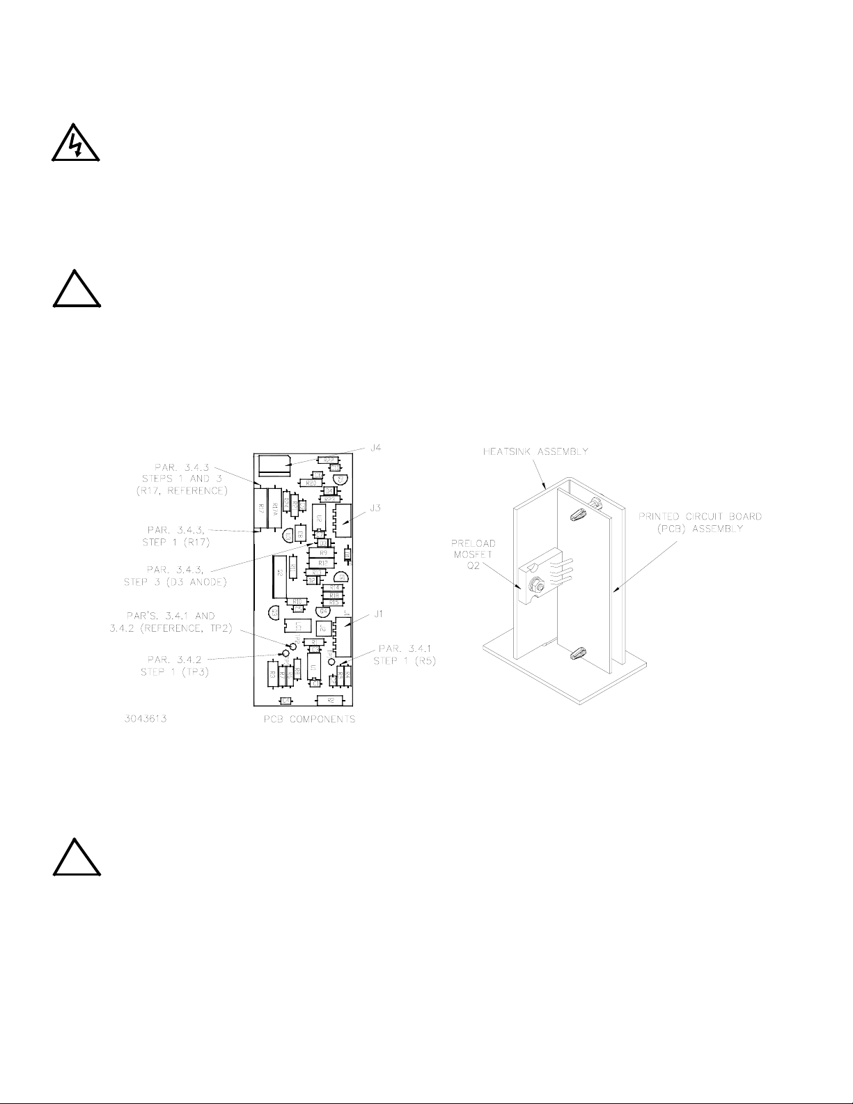
The Transition Circuit assembly Printed Circuit Board (PCB) is shipped assembled to the Heatsink with the preload-MOSFET mounted directly on the heatsink (Figure 1).
front panel.
FIGURE 1. TRANSITION CIRCUIT ASSEMBLY, COMPONENT LOCATIONS
1. Install the Transition Circuit assembly as shown in Figure 2 using the ventilation hole identified in the figure
and the screw provided in this kit. The screw is inserted up through the bottom of the chassis into the plastic
grommet of the heatsink. The plastic grommet keeps the Transition Circuit assembly electrically isolated from
the chassis.
CAUTION: When routing cables, ensure that the cables stay clear of the Output Module (A2) Fan and
!
2. Cable assembly P/N 118-1267 (provided in the Kit) has a 3-pin connector with two wires, each having non-isolated ring lugs. Remove the screws and lockwashers from J4M and J2M on A4A8, then add the wires from the
cable assembly to the wires already connected to J4M and J2M as follows (see Figure 2 for the location of
A4A8 in the chassis, Figure 3 for location of J4M and J2M and Figure 6 for cable routing):
• red/white wire to A4A8- J4M
• black/white wire to A4A8- J2M
KEPCO, INC. 131-38 SANFORD AVENUE FLUSHING, NY. 11355 U.S.A. TEL (718) 461-7000 FAX (718) 767-1102
2 228-1746 REV 2 071812
Auxiliary Power Supply (A5).
http://www.kepcopower.com email: hq@kepcopower.com
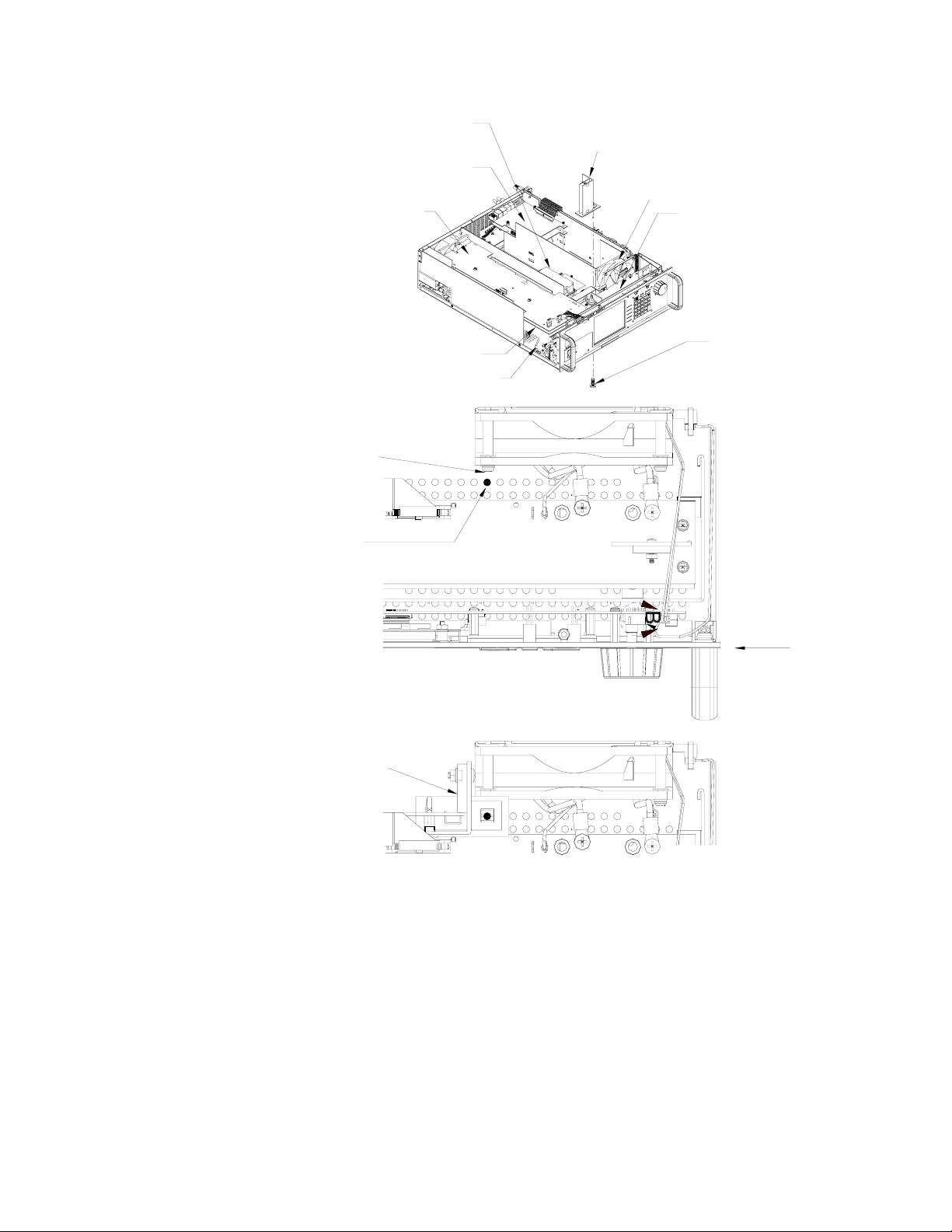
AUXILIARY
POWER SUPPLY A5
TRANSITION CIRCUIT
ASSEMBLY A7A3
(SEE DETAILS "A" AND "B")
A2A5 ASSEMBLY
(SEE FIGURE 5.)
A4A3 ASSEMBLY
(SEE FIGURE 6,)
A4A1 ASSEMBLY
CHASSIS GROUND CONNECTION
FAN MOUNTING
SCREW
INSERT SCREW IN THIS
VENTILATION HOLE (IN LINE
WITH FAN MOUNTING SCREW)
TO MOUNT TRANSITION
CIRCUIT ASSEMBLY A7A3.
OUTPUT MODULE
(A2) FAN)
A4A8 ASSEMBLY
(SEE FIGURE 4.)
KEPCO P/N 101-0328
SCREW, TPTH,
8-18 X 0.625 IN.
NOTE: For flush mounting of
chassis in rack,
contact Kepco
(See Note)
FRONT
PANEL
3043609
DETAIL "A"
(PARTIAL TOP VIEW)
A7A3 SCREW LOCATION
TRANSITION
CIRCUIT
A7A3
DETAIL "B"
(PARTIAL TOP VIEW)
A7A3 INSTALLED
FIGURE 2. BOP 1KW COMPONENT LOCATIONS
3. Install the 4-pin cable assembly (P/N 118-1266) on Transition Circuit A7A3J3 of the PCB (see Figure 1). Route
the cables as shown by Figure 6. This cable has three (3) unterminated wires. Determine the needed length,
cut the wire and remove the insulated sleeving (approximately 0.15"), then solder each wire to the indicated
point (see Figure 3 for A4A8 component locations and Figure 6 for cable routing):
• red wire to A4A8D1 Cathode
• black wire to A4A8D1 Anode
• white wire to A4A8TP2
KEPCO, INC. 131-38 SANFORD AVENUE FLUSHING, NY. 11355 U.S.A. TEL (718) 461-7000 FAX (718) 767-1102
http://www.kepcopower.com email: hq@kepcopower.com
071812 228-1746 REV 2 3
Loading...