


 Loading...
QUICK START GUIDE
KEPCO An ISO 9001 Company.
KLP
KLP POWER SUPPLY
This guide gives a brief introduction to the KLP Power supply, shows simple load connections, and allows you to verify the power supply is working. The guide also shows you how to use the front panel controls to perform the most commonly used functions.
Accessing Manuals. First determine your Firmware Version (see below), then download the KLP User Manual and Developer’s Guide from www.kepcopower.com/support/opmanls.htm#klp. Refer to the KLP User Manual for full specifications, installation considerations and operating instructions. An Installation/ Operation Summary includes hyperlinked references to detailed procedure, but which can be printed as a handy reference. Refer to the KLP Developer’s Guide for a full description of the digital interfaces, their associated drivers, and the SCPI command language.
Firmware Version. Refer to www.kepcopower.com/utility/util.htm to determine which firmware version is installed. The KLP can be upgraded to the latest version at no cost using the Kepco Upgrade Utility, also available at www.kepcopower.com/utility/util.htm.
Accessing Drivers. Drivers are accessed from www.kepcopower.com/drivers/drivers-dl3.htm.
CONTENTS
DESCRIPTION. . . . . . . . . . . . . . . . . . . . . . . . . . . . . . . . . . . . . . . . . . . . . . . . . . . . . . . . . . . . . . . . . . . . . 2 UNPACKING. . . . . . . . . . . . . . . . . . . . . . . . . . . . . . . . . . . . . . . . . . . . . . . . . . . . . . . . . . . . . . . . . . . . . . . 2 EQUIPMENT SUPPLIED. . . . . . . . . . . . . . . . . . . . . . . . . . . . . . . . . . . . . . . . . . . . . . . . . . . . . . . . . . . . . 2 ACCESSORIES. . . . . . . . . . . . . . . . . . . . . . . . . . . . . . . . . . . . . . . . . . . . . . . . . . . . . . . . . . . . . . . . . . . . 3 SAFETY. . . . . . . . . . . . . . . . . . . . . . . . . . . . . . . . . . . . . . . . . . . . . . . . . . . . . . . . . . . . . . . . . . . . . . . . . . 3 PRELIMINARY OPERATIONAL CHECK. . . . . . . . . . . . . . . . . . . . . . . . . . . . . . . . . . . . . . . . . . . . . . . . . 4 INSTALLATION. . . . . . . . . . . . . . . . . . . . . . . . . . . . . . . . . . . . . . . . . . . . . . . . . . . . . . . . . . . . . . . . . . . . 5
Input Connections. . . . . . . . . . . . . . . . . . . . . . . . . . . . . . . . . . . . . . . . . . . . . . . . . . . . . . . . . . . . . . . 5 Load Connections. . . . . . . . . . . . . . . . . . . . . . . . . . . . . . . . . . . . . . . . . . . . . . . . . . . . . . . . . . . . . . . 5 Local Sensing (Factory Default). . . . . . . . . . . . . . . . . . . . . . . . . . . . . . . . . . . . . . . . . . . . . . . . . . . . . 6 Remote Sensing Select. . . . . . . . . . . . . . . . . . . . . . . . . . . . . . . . . . . . . . . . . . . . . . . . . . . . . . . . . . . 6 Analog I/O Connections. . . . . . . . . . . . . . . . . . . . . . . . . . . . . . . . . . . . . . . . . . . . . . . . . . . . . . . . . . . 7 GPIB Connections. . . . . . . . . . . . . . . . . . . . . . . . . . . . . . . . . . . . . . . . . . . . . . . . . . . . . . . . . . . . . . . 7 RS 232 Connections (Standard Models). . . . . . . . . . . . . . . . . . . . . . . . . . . . . . . . . . . . . . . . . . . . . . 7 LAN Connections (E-Series Models). . . . . . . . . . . . . . . . . . . . . . . . . . . . . . . . . . . . . . . . . . . . . . . . . 7
OPERATION. . . . . . . . . . . . . . . . . . . . . . . . . . . . . . . . . . . . . . . . . . . . . . . . . . . . . . . . . . . . . . . . . . . . . . . 7 Turning the Power Supply On. . . . . . . . . . . . . . . . . . . . . . . . . . . . . . . . . . . . . . . . . . . . . . . . . . . . . . 7 Enabling/disabling Output Power. . . . . . . . . . . . . . . . . . . . . . . . . . . . . . . . . . . . . . . . . . . . . . . . . . . . 8 Checking or changing Voltage/Current Setpoints. . . . . . . . . . . . . . . . . . . . . . . . . . . . . . . . . . . . . . . 8 Virtual Model Setting. . . . . . . . . . . . . . . . . . . . . . . . . . . . . . . . . . . . . . . . . . . . . . . . . . . . . . . . . . . . . 8 Setting voltage or current. . . . . . . . . . . . . . . . . . . . . . . . . . . . . . . . . . . . . . . . . . . . . . . . . . . . . . . . . . 9 Last Setting Recall. . . . . . . . . . . . . . . . . . . . . . . . . . . . . . . . . . . . . . . . . . . . . . . . . . . . . . . . . . . . . . 10 Viewing/Changing Overvoltage or Overcurrent Protection Values. . . . . . . . . . . . . . . . . . . . . . . . . 10
KLP OUTLINE DIMENSIONS . . . . . . . . . . . . . . . . . . . . . . . . . . . . . . . . . . . . . . . . . . . . . . . . . . . . . . . . 11
KEPCO, INC. |
131-38 SANFORD AVENUE |
FLUSHING, NY. 11355 U.S.A. TEL (718) 461-7000 |
FAX (718) 767-1102 |
|
|
http://www.kepcopower.com |
email: hq@kepcopower.com |
|
|
©2012, KEPCO, INC |
|
|
|
|
Data subject to change without notice |
228-1616 REV 6 |
070312 |
||

DESCRIPTION. The KLP Power Supply Series are universal input, automatic crossover, 1200-watt constant power, voltage/current stabilizers with a full rectangular output characteristic. There are seven standard models (also referred to as -1200) and seven E -Series models (formerly referred to as -1.2K) (see Table 1). The standard models are GPIB and RS 232 compatible; the E-Series models are GPIB and LAN compatible; all models allow remote analog programming. For each model a multitude of virtual models can be configured. The “rated voltage, maximum current at rated voltage” and “rated current and maximum voltage at rated current” parameters define the virtual models available within the limit of 1200 Watts of output power.
TABLE 1. MODEL PARAMETERS
|
Rated |
Maximum |
Minimum |
Rated |
Maximum |
Ripple |
|
|
|
and |
Efficiency |
||||||
Model number |
Voltage |
current for |
programmable |
Current |
voltage for |
|||
noise |
@115 Va-c |
|||||||
|
Range(1) |
rated voltage |
current |
Range(1) |
rated current |
|||
|
p-p(2) |
|
||||||
KLP 10-150(3) |
0-10V |
120A@10V |
1.9A |
0-150A |
8V@150A |
60 mV |
80% |
|
KLP 20-120(3) |
0-20V |
60A@20V |
1.5A |
0-120A |
10V@120A |
60 mV |
82% |
|
KLP 36-60(3) |
0-36V |
33.3A@36V |
0.8A |
0-60A |
20V@60A |
60 mV |
83% |
|
KLP 75-33(3) |
0-75V |
16A@75V |
0.4A |
0-33.3A |
36V@33.3A |
60 mV |
84% |
|
KLP 150-16(3) |
0-150V |
8A@150V |
0.2A |
0-16A |
75V@16A |
125 mV |
86% |
|
KLP 300-8(3) |
0-300V |
4A@300V |
0.1A |
0-8A |
150V@8A |
150 mV |
87% |
|
KLP 600-4(3) |
0-600V |
2A@600V |
0.05A |
0-4A |
300V@4A |
150 mV |
88% |
(1) The maximum current and voltage are constrained by the 1200 watt power limitation.
(2) Bandwidth: 20MHz; low frequency ripple may be higher at loads less than 30 Watts.
(3) Specifications listed apply to both standard (-1200) and E-Series (suffix E) models.
UNPACKING. This instrument has been thoroughly inspected and tested prior to packing and is ready for operation. After careful unpacking, inspect for shipping damage before attempting to operate. Perform the PRELIMINARY OPERATIONAL CHECK. If any indication of damage is found, file an immediate claim with the responsible transport service.
EQUIPMENT SUPPLIED. See Table 2.
TABLE 2. EQUIPMENT SUPPLIED
ITEM |
PART NUMBER |
QUANTITY |
|
|
|
|
|
|
Source power connector |
142-0381 |
1 |
|
|
|
Jumper (24 AWG or larger bus wire) for local sensing connections |
172-0585 |
2 |
|
|
|
Analog I/O port mating connector |
142-0528 |
1 |
|
|
|
Nut, 1/4-20, with captive lockwasher (on output studs of 10V, 20V and 36V models only) |
102-0175 |
2 |
|
|
|
Quick Start Guide * |
228-1616 |
1 |
|
|
|
* User Manual and Developer’s Guide are available as free downloads from: |
|
|
www.kepcopower.com/support/opmanls.htm#klp |
|
|
Drivers are available as free downloads from
www.kepcopower.com/drivers/drivers-dl3.htm#klp
KEPCO, INC. |
131-38 SANFORD AVENUE |
FLUSHING, NY. 11355 U.S.A. |
TEL (718) 461-7000 |
FAX (718) 767-1102 |
|
|
http://www.kepcopower.com |
email: hq@kepcopower.com |
|
||
2 |
228-1616 REV 6 |
070312 |
ACCESSORIES. See Table 3.
TABLE 3. ACCESSORIES
|
ITEM |
|
FUNCTION |
|
|
KEPCO |
|||
|
|
|
|
PART NUMBER |
|||||
|
|
|
|
|
|
|
|
|
|
|
|
|
|
|
|
|
|
|
|
|
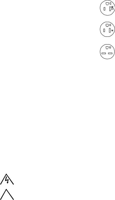
Line Cord Set (125V/20A) |
2.5m long cord set, provides for source power |
NEMA 5-20R |
118-0776 |
|||||
|
|
|
|
|
connection. Mates with NEMA 5-20R receptacle |
|
|
|
|
|
|
|
|
|
(see adjacent figure). Supports rated load power |
|
|
|
|
|
|
|
|
|
over mains voltage range of 90-136V a-c. |
|
|
|
|
|
|
|
|
|
|
|
|
|
|
|
Line Cord Set (125V/15A) |
2.5m long cord set, provides for source power |
NEMA 5-15R |
118-1136 |
|||||
|
|
|
|
|
connection. Mates with NEMA 5-15R receptacle |
|
|
|
|
|
|
|
|
|
(see adjacent figure). Supports restricted load |
|
|
|
|
|
|
|
|
|
power over mains voltage range of 90-136V a-c |
|
|
|
|
|
|
|
|
|
(contact Kepco Sales Engineering for details). |
|
|
|
|
|
|
|
|
|
|
|
|
|
|
|
Line Cord Set (250V/15A) |
2.5m long cord set, provides for source power |
NEMA 6-15R |
118-1137 |
|||||
|
|
|
|
|
connection. Mates with NEMA 6-15R receptacle |
|
|
|
|
|
|
|
|
|
(see adjacent figure). Supports rated load power |
|
|
|
|
|
|
|
|
|
over mains voltage range of 180-265V a-c. |
|
|
|
|
|
|
|
|
|
|
|
|
|
|
|
IEEE 488 (GPIB) Cable, 1m long |
Connect KLP Power Supply to GPIB bus. |
|
|
SNC 488-1 |
||||
|
|
|
|
|
|
|
|
|
|
|
IEEE 488 (GPIB) Cable, 2m long |
Connect KLP Power Supply to GPIB bus. |
|
|
SNC 488-2 |
||||
|
|
|
|
|
|
|
|
|
|
|
IEEE 488 (GPIB) Cable, 4m long |
Connect KLP Power Supply to GPIB bus. |
|
|
SNC 488-4 |
||||
|
|
|
|
|
|
|
|
|
|
|
Chassis Slide |
Allows rack-mounted units to slide in and out. Two (2) slides required |
108-0239 |
||||||
|
|
|
|
|
per power supply. |
|
|
(Jonathan |
|
|
|
|
|
|
|
|
|
|
375-QD Series) |
|
|
|
|
|
|
|
|
|
|
|
Analog Connector Backshell |
Locks analog port mating connector to KLP via jackscrews. |
108-0204 |
||||||
|
|
|
|
|
|
|
|
|
|
|
Loop Back Test Connector |
Used for verification of RS 232 operation. |
|
195-0112 |
|||||
|
|
|
|
|
|
|
|
|
|
|
Null Modem Cable, 10 ft. |
Connect RS 232 port with controlling computer, DB9F to DB9F, 10 feet |
118-1176 |
||||||
|
|
|
|
|
long. |
|
|
|
|
|
|
|
|
|
|
|
|
|
|
|
Null Modem Cable, 1 ft. |
Used for Master/Slave connections. Connects RS 232 ports of stacked |
118-1220 |
||||||
|
|
|
|
|
power supplies, DB9F to DB9F, one foot long. |
|
|
|
|
|
|
|
|
|
|
|
|
|
|
|
LAN Patch cable |
Connects KLP LAN port to LAN, 10 ft long. |
|
118-1115 |
|||||
|
|
|
|
|
|
|
|
|
|
|
Support bracket, rear |
Provides extra support to rear of rack-mounted unit if needed. Two |
128-2306 |
||||||
|
|
|
|
|
brackets required per unit. Each bracket requires 2 screws and 2 |
|
|
||
|
|
|
|
|
washers. See Figure 4, sheet 1, Detail “A” for requirements. |
|
|
||
|
|
|
|
|
|
|
|
|
|
SAFETY. See Table 4 |
|
|
|
|
|
||||
|
|
|
|
|
|
TABLE 4. SAFETY SYMBOLS |
|
|
|
|
|
|
|
|
|
|
|
|
|
|
|
|
SYMBOL |
|
MEANING |
|
|
|
|
|
|
|
|
|
|
|
|
|
|
|
|
|
|
|
|
|
|
|
|
|
|
|
|
|
|
CAUTION: RISK OF ELECTRIC SHOCK. |
|
|
|
|
|
|
|
|
|
|
|
|
|
|
|
|
|
|
|
|
|
|
|
|
|
! |
|
|
CAUTION: REFER TO REFERENCED PROCEDURE. |
|
|
||
|
|
|
|
|
|
|
|||
|
|
|
|
|
|
|
|
|
|
|
|
|
WARNING |
|
INDICATES THE POSSIBILITY OF BODILY INJURY OR DEATH. |
|
|
||
|
|
|
|
|
|
|
|
|
|
|
|
|
CAUTION |
|
INDICATES THE POSSIBILITY OF EQUIPMENT DAMAGE. |
|
|
||
|
|
|
|
|
|
|
|
|
|
KEPCO, INC. |
131-38 SANFORD AVENUE |
FLUSHING, NY. 11355 U.S.A. |
TEL (718) 461-7000 |
FAX (718) 767-1102 |
|
|
http://www.kepcopower.com |
email: hq@kepcopower.com |
|
||
070312 |
228-1616 REV 6 |
3 |
PRELIMINARY OPERATIONAL CHECK. A simple operational check after unpacking and before equipment installation is advisable to ascertain whether the power supply has suffered damage resulting from shipping.
NOTE: This test must be performed with all I/O ports disconnected, and ANALOG I/O SETTINGS switch positions 3, 4 and 5 set to OFF (up).
1With POWER circuit breaker set to OFF position, connect the power supply to source power (see See “Input Connections.” on page 5.).
2With no load connected, set POWER circuit breaker to the ON position. Each time the unit is turned on an internal self-test is performed (see “Turning The Power Supply On.” on page 7). After the test has been successfully completed, the status display reads SET (setpoint mode), the DC VOLTS display reads 0 Volts and the DC AMPERES display reads minimum Amperes (see Note 1, below).
NOTES: 1. A minimum programmed current (actual value depends on model) is required to ensure proper operation of the power supply under all load conditions. Programmed current is automatically set to be at least the minimum current.
2.If an error indication is blinking in the Status display, refer to User Manual for an explanation of error codes.
3Rotate VOLTAGE adjust knob clockwise. Verify that DC VOLTS display increases in large (X 100) increments.
4Press and rotate VOLTAGE adjust knob clockwise. Verify the DC VOLTS display increases in finer increments than step 3, then release knob.
5Adjust VOLTAGE adjust knob clockwise until Status display reads >MAX. Tap either VOLTAGE or CURRENT adjust knob once to enter values. Verify Status display is blank
6Connect a digital voltmeter (DVM) to the (M+) and (M–) terminals on the rear panel.
7Press and release DC OUTPUT switch to enable the output. Verify DC OUTPUT indicator lights.
8Compare the programmed output voltage value (step 5) with the voltage reading of the DVM; the difference between the two should not exceed 0.05% of the maximum voltage of the unit.
9Compare the voltage reading of the DC VOLTS display with that of the DVM; the difference between the two should not exceed 0.1% of the maximum voltage of the unit.
10Enter different value for output voltage, then repeat steps 4 and 5 using different values for programmed voltage.
11Disable the output by pressing and releasing DC OUTPUT switch; verify front panel DC VOLTS and DC AMPERES displays read 0.0V and minimal current and the DC OUTPUT indicator is off.
12Set POWER ON/OFF circuit breaker to OFF and disconnect from source power, load and test equipment.
KEPCO, INC. |
131-38 SANFORD AVENUE |
FLUSHING, NY. 11355 U.S.A. |
TEL (718) 461-7000 |
FAX (718) 767-1102 |
|
|
http://www.kepcopower.com |
email: hq@kepcopower.com |
|
||
4 |
228-1616 REV 6 |
070312 |
Loading...