

1
TS-990SE
HF/50MHz All-Mode Transceiver
January 2013
We are pleased to inform you of our new HF/ 50MHz all mode Transceiver for
Amateur Radio.
1. SCHEDULE
Launch: End of February 2013
New Product Release Information

2
2. MAIN FEATURES
2-1. Main receiver
Down conversion format for all amateur bands
A key point in tapping maximum performance from the 1st mixer in actual operation
(say, CW operation) is to prevent the outflow of unnecessary signals, other than the
target signal, from the mixer to the subsequent stage. This is because it can tap the
maximum performance of the digital IF filter using the DSP in the final IF stage. The
TS-990 main reception unit employs a 1st IF frequency 8.248 MHz down-conversion
format. It achieves superior close-in dynamic range unattainable through conventional
up-conversion formats. Even if the interference is a close-in frequency, the receiver
maintains a relatively flat dynamic range, which you can tune without losing your target
signal.
Newly developed mixer
In place of the Double Balanced Mixer, which uses the conventional J-FET, we have
installed the newly developed Double Balanced Grounded Switch Type in the 1st mixer
circuit, which is the heart of the main receiver. The transceiver is also equipped with a
pre-selector function that varies the tuning frequency in tandem with the reception
frequency. It effectively dampens strong interference signals that cannot be minimized
through bandpass filters on dedicated amateur bands. Furthermore, we have achieved
a +40dBm class of third-order intercept points for the signal path of the 1st mixer,
based on selected circuits and components, and by employing large-sized core toroidal
coils for protecting against distortion based on large input signals, as well as using
relays for the signal switching.
Newly developed narrow-band High-IP roofing filter
The transceiver uses a down-conversion method for all amateur band reception, and
features five types of High-IP roofing filter. Narrow bandpass widths selectable are 500
Hz and 270 Hz for CW operation, 2.7kHz for SSB and 6kHz and 15kHz, which are
suitable for AM/FM. These filters are automatically selected in tandem with DSP-based
final bandpass settings. Of course, manual switching is possible as well.
Newly developed VCO frequency division 1st local oscillator
The TS-990 Local Oscillator Circuit is an independent configuration that combines the
main
receiver and VCO Frequency Division/DDS Direct, the sub-receiver and DDS Direct,
and the transmission unit and conventional PLL, with the targeted signal system. The
newly developed VCO frequency division format is used for the 1st local oscillator of
the main
receiver. The device achieves favourable C/N characteristics that rival the
DDS direct format, and relatively spurious-free local oscillation signals that are
characteristic of the PLL format, by oscillating and dividing the VCO at higher
frequencies than the intended frequency. It is possible to convert it to 1st IF in a pure
state without leaking the target signal as noise by reducing static noise from the local
oscillator and increasing the C/N ratio.

3
Equipped with ±0.1ppm TCXO
The standard equipment includes a TCXO (temperature-compensated crystal
oscillator), which stabilizes frequencies at ±0.1ppm as the standard signal source.
Unlike OCXO (Oven Controlled crystal Oscillator), which requires warm-up time, this
device can start up quickly even from the power-off position, while maintaining a high
level of stability. It is in compliance with European energy-saving standard Lot6. Power
consumption in stand-by energy-saving mode is less than 0.5 W. A BNC connector on
the rear pannel provides 10MHz reference I/O.
2-2. Sub receiver
Down conversion for amateur bands below 15m
The sub-receiver features reception performance that has exceeded its class since
going on sale, thus further refining this popular receiver on the TS-590.
Because this is particularly the case on the front end, where it employs circuit
configuration that makes down-conversion possible on the leading five amateur bands,
it can be used in actual operation despite being just a sub-receiver.
* The IF bandwidth for 160m/80m/40m/20m/15m bands is (SSB/CW/FSK/PSK) for
frequency levels 2.7 kHz or below.
Roofing filter, 500 Hz, 2.7 kHz
Frequencies of 500 Hz and 2.7 kHz are standard for sub-receiver roofing filters.
You can maintain a more or less flat dynamic range even if interference impinges on
your reception frequency, thanks to superior close-in dynamic range properties. You
can clearly catch signals under conditions made problematic by strong close-in
interference signals.
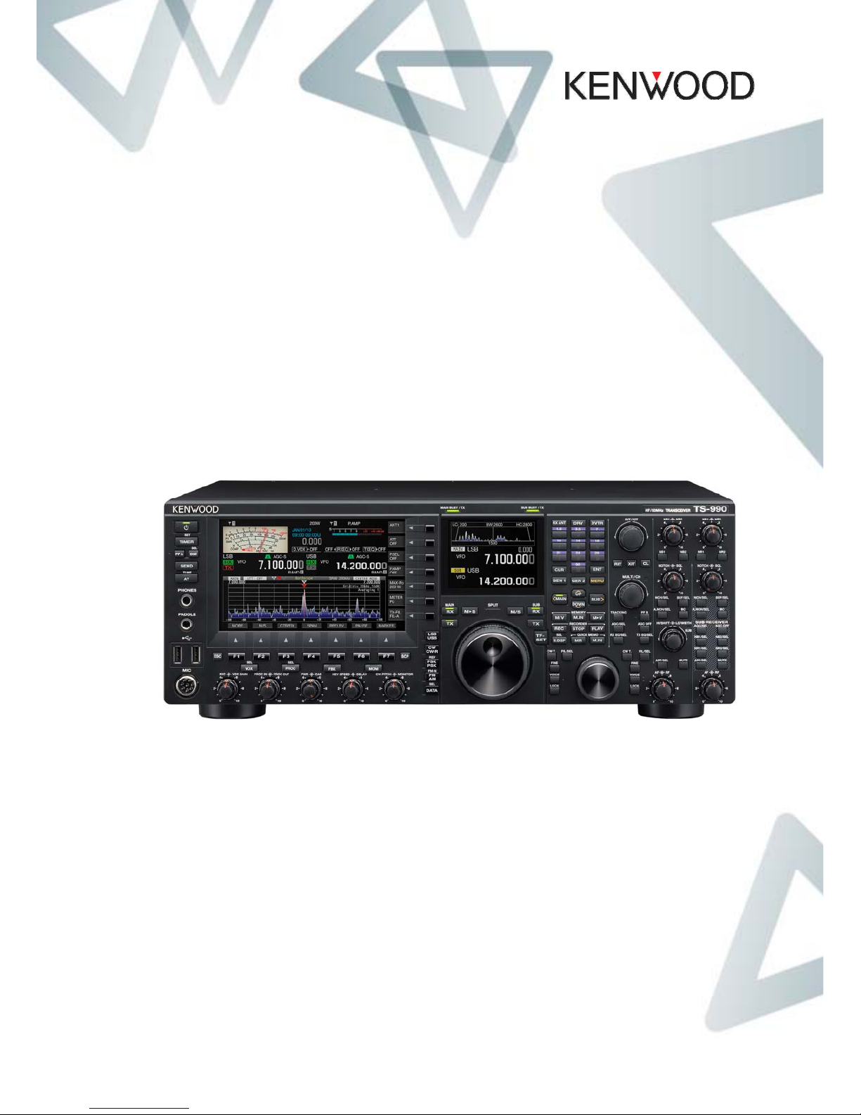
2-3. Triple DSP
Equipped with dedicated DSP for the main-receiver,
sub-receiver and band scope
Kenwood continues to provide quality sound transmission that is
unattainable through analogue circuits. By loading the worldpremiere DSP on the TS-950 and achieving IF AGC control on
the TS-870 by using DSP for the first time for amateur wireless
devices. As a culmination of the foregoing developments, three
DSP units are used, one on each major block of the TS-990.
By distributing the signal processing of the main IF, band scope,
and sub-IF, we have realized ample digital signal processing.
(FM mode is AF DSP processing.)
Advanced AGC control
The reception sound quality of SSB and CW is not solely determined by audio
frequency and filter delay properties. AGC characteristics play a very significant role as
4
well. The opinion of many of our fans that “even for long periods of time they never get
tired of listening” is due to the characteristics of Kenwood’s AGC. The TS-990 goes a
long way in helping further refine the Kenwood tone by innovating not only the AGC
control algorithm on the DSP but also the analogue AGC unit as well.
Exacting chassis design
The sound quality of the built-in speakers is largely determined by the chassis structure.
With the TS-990, we have been able to minimize unnecessary chassis vibration
through multiple simulations from the conceptual phase. The Kenwood tone is
supported not only by circuits and DSP but also by exact chassis design.
Extensive interference elimination
and noise reduction functions
IF filter bandwidth variability
IF filter A/B/C one-touch switch instantly
IF notch
Band elimination filter function
The noise blanker function (NB1/NB2)
DSP-based noise reduction function (NR1/NR2)
Beat cancel function (BC1/BC2)
Audio peak filter
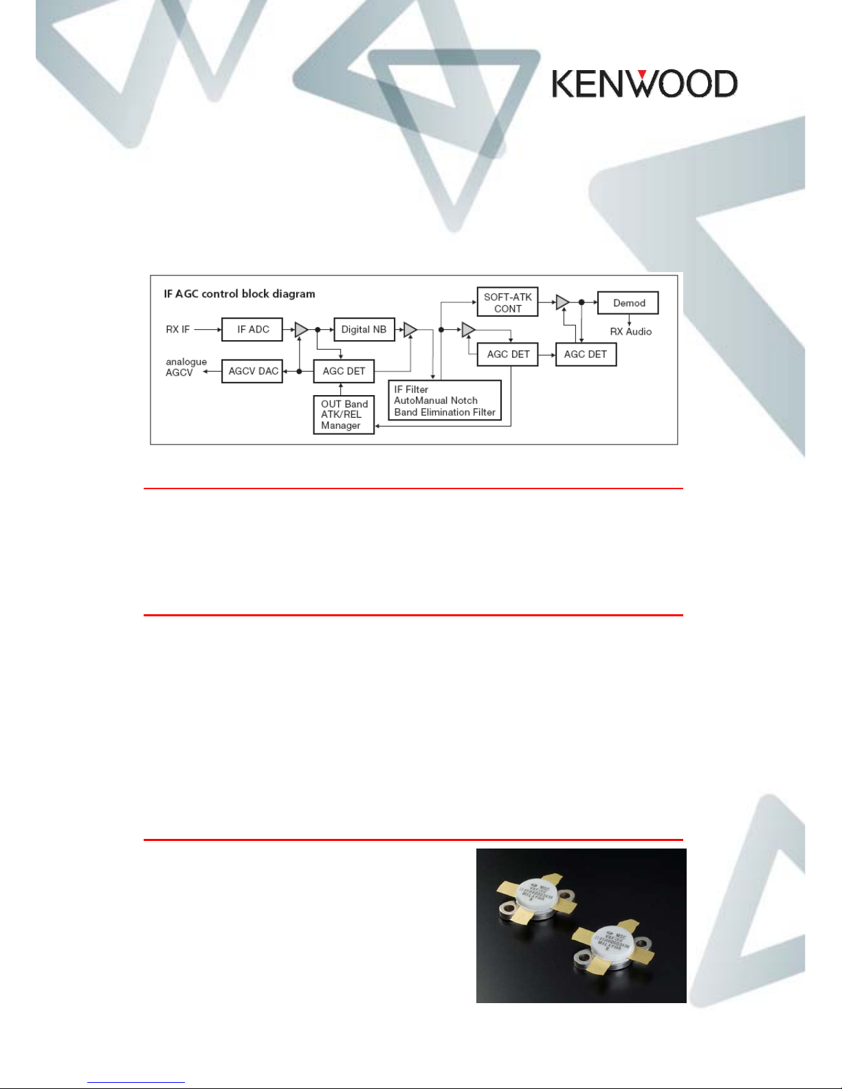
2-4. Transmitter
High reliability design
The device uses POWER MOSFET VRF150MP,
which runs at 50V, with push-pull. You can obtain
a high, stable output of 200 W on all bands. You
can achieve superior IMD properties by pursuing
bias and matching conditions in order to fully
exploit the 30FET attributes. Further, you can
realize Kenwood’s distinctive tone by amplifying
the clean modulated signal produced by DSP with
an amplifier that exhibits excellent linearity.
 Loading...