

Page 1
KENWOOD
INSTRUCTION MANUAL
Page 2

INTRODUCTION
You are now the owner of our most recent product, the TS-430S amateur band transceiver and
general coverage receiver. Please read this instruction manual carefully before placing your new
transceiver in service. This equipment has been carefully engineered and manufactured to rigid
quality standards, and should give you satisfactory and dependable operation for many years.
AFTER UNPACKING: Accessaries
• Shipping container: Warranty card*.................................................................... 1
Save the boxes and packing in the event Instruction Manual (B50-4006-30)
your unit needs to be transported for re- Fuse (20A) (F05-2034-05)
mote operation, maintenance, or service. Calibration cable (E31 -21 54-05)....................................... 1
• The following explicit definitions apply in DC power cable (E30-1638-05).......................................... 1
this manual: 7 pin DIN plug {E07-0751-05)
Note: If disregarded, inconvenience 8 pin DIN plug (E07-0851-05)
only. * Included only for U.S.A.
No risk of equipment damage or personal injury.
Caution: Equipment damage may occur, but not personal injury.
......................................
..................................................
.............................................
.............................................
1
1
1
1
CONTENTS
SECTION 1. SPECIFICATIONS...................................................................................................................................................... 3
SECTION 2. FEATURES................................................................................................................................................................ 4
SECTION 3. PREPARATION FOR USE......................................................................................................................................... 4
SECTION 4. CONTROLS, INDICATORS AND CONNECTORS
4.1 FRONT AND TOP PANELS.................................................................................................................................. 6
4.2 REAR PANEL........................................................................................................................................................ 8
SECTION 5. OPERATION
5.1 RECEPTION......................................................................................................................................................... 9
5.2 TRANSMISSION..................................................................................................................................................11
5.3 VOX OPERATION.................................................................................................................................................13
5.4 SEMI-BREAK-IN OPERATION.............................................................................................................................13
5.5 OPERATION WITH A LINEAR AMPLIFIER.........................................................................................................13
5.6 CW OPERATION..................................................................................................................................................13
5.7 KEY BOARD FUNCTIONS...................................................................................................................................14
5.8 MOBILE OPERATION..........................................................................................................................................17
5.9 FIXED STATION OPERATION............................................................................................................................ 19
SECTION 6. ADDITIONAL INFORMATION.................................................................................................................................. 20
SECTION 7. TROUBLE SHOOTING.............................................................................................................................................24
SECTIONS. OPTIONAL ACCESSORIES......................................................................................................................................25
SECTIONS. INTERNAL VIEWS.....................................................................................................................................................27
SECTION 10. RADIO FREQUENCY ALLOCATION.....................................................................................................................29
SECTION 11. BLOCK DIAGRAM..................................................................................................................................................29
SECTION 12. SCHEMATIC DIAGRAMS...........................................................................................................................30 ~ 34
NOTE: —---------------------------------------------------------------------------------------------------------------------------------------------------------------------------
Before connecting or disconnecting the AC power plug, always be sure to set the POWER switches
of the TS-430S and the PS-430 to OFF.
Page 3

I SECTION 1. SPECIFICATIONS
[GENERAL]
Transmitter Frequency Range;
Receiver Frequency Range:
Mode:
Antenna Impedance:
Power Requirement:
Power Consumption:
Dimensions:
Weight:
[TRANSMITTER]
Final Power Input:
—Mode
Band ~~——
1 60m - 1 5m band
10m band
Modulation:
Carrier Supression:
Unwanted Sideband Suppression;
Harmonic Content;
Maximum Frequency Diviation (FM):
Microphone Impedance:
[RECEIVER]
Circuitry:
Intermediate Frequency:
Sensitivity:
Frequency
150kHz-500kHz
Mode
SSB/CW(10dBS/N)
AM(10dBS/N)
FM (30dBS/N) -
FM(12dBSINAD)
160, 80,40, 30, 20,17*, 15,12', 10 meter Amateur bands
150 kHz to 30 MHz
A3J (LSB, USB), A1 (CW), A3 (AM), F3 (FM)
A3J (LSB, USB), A1 (CW), A3 (AM), F3 (FM
12.0 to 16.0 V DC (13.8 V nominal)
20A approx, in transmit mode
1.2A approx, in receive mode
270 (10.6)W X 96 (3.8)H x 257 (10.1) D mm (inch)
6.5 kg (14.3 lbs.)
SSB CW
250WPEP
250WPEP
SSB = Balanced Modulation
FM = Variable Reactance Direct Shift
(with FM-430 optional accessory)
AM = Low Level Modulation (IF stage)
Better than 40 dB
Better than 50 dB
Less than -40 dB
±5 kHz (with FM-430 optional accessory)
500i2 to 50 ki2
SSB, CW, AM = Double conversion Superheterodyne
FM = Triple Conversion Superheterodyne
1st IF = 48.055 MHz
2nd IF = 8.83 MHz
3rd IF = 455 kHz (FM only)
200WDC
200WDC
500kHz- 1.8MHz
Less than 1 //V
Less than 13 //V
Less than 4 yuV
Less than 40 //V
-
-
-
........................
FM
—
120W
1.8MHz-30MHz
Less than 0.25 aV
Less than 2.5 fN
*Less than 1 //V
*Less than 0.7 //V
OPTION)
AM
60W
60W
Image Ratio:
IF Rejection:
Selectivity;
More than 70 dB (1.8 to 30 MHz)
More than 50 dB (FM-3rd image ratio)
More than 70 dB (1.8 to 30 MHz)
Selectivity
-6dB
Mode ~
--------------------------------SSB/CW
AM *1
FM *2
...^^
2.4 kHz
6 kHz
15 kHz
1 with YK-88A optional filter
2 with FM-430 optional accessory
Frequency Stability:
Frequency Accuracy:
RIT Variable Range:
Audio Output Impedance:
Audio Output Power:
Better than ± 30 x 10“® (0°C to +50°C), Within ± 200 Hz from 1 to
60 minutes after turn-on: within ±30 Hz any 30 minute period
thereafter
Better than 10x10~®
More than ± 1 kHz
4i2 to 16Q
More than 1.5W across 8Q (at 10% distortion)
Note: Circuit and ratings subject to change without notice due to developments in technology.
-60 dB
4.4 kHz
12 kHz
32 kHz
Page 4

SECTION 2. FEATURES
150 kHz - 30 MHz GENERAL COVERAGE RECEIVER
ALL MODE OPERATION
Operating mode include USB, LSB, CW, and AM, both
transmit and receive, with FM optionally available
using the FM-430 frequency modulation unit (installs easi
ly inside the transceiver). Mode selection is made
by front panel mode keys with adjacent LED indicators.
SUPERIOR RECEIVER DYNAMIC RANGE
The receiver front-end has been carefully designed to pro
vide an exceptionally wide dynamic range, through
the use of 2SK125 junction-type FET's in the RF amplifier
and balanced mixer circuits.
DUAL DIGITAL VFO's
• 10 Hz step dual digital VFO's include band and mode
information, allowing split frequency or cross-band
operation.
• A STEP switch is provided to permit tuning in 10 Hz
(10 kHz/revolution of the tuning knob), or 100 Hz (100
kHz/revolution) steps.
• An A = B switch is provided to bring the idle VFO to the
active VFO mode and frequency.
• A VFO LOCK switch is provided.
• The RIT control allows shifting the receive frequency in
either VFO or memory mode operation.
EIGHT MEMORY CHANNELS
• Each memory stores frequency, mode and band infor
mation.
• The memory CH 8 stores both a receive and a transmit
frequency for split-frequency memory operation.
• A front panel MR switch is provided to allow the opera
tor to operate each of the eight memories as an inde
pendent VFO, or as a fixed frequency.
LITHIUM BATTERY MEMORY BACK-UP
All memory and VFO information are backed-up by an in
ternal lithium battery (estimated 5 year life).
IF SHIFT CIRCUIT
The apparent IF passband may be shifted to place interfer
ing signals outside the passband, while keeping the de
sired signal optimally placed for best signal-to-noise ratio.
TUNABLE NOTCH FILTER
SPEECH PROCESSOR
The speech processor uses an audio compression ampli
fier and change in the ALC time constant, resulting in sub
stantially increased "talk-power".
ALL SOLID-STATE
The TS-430S runs 250W PEP input on CW, on 160-10
meters. In the AM mode, it runs 60W input, all
bands. In the FM mode (optional FM-430 unit installed), it
runs 1 20W input. A built-in cooling fan, plus other protec
tion circuitry assures maximum final amplifier reliability.
Both the receiver and the solid-state wide band final am
plifier requires no tuning.
NOISE BLANKER
An effective noise-blanker eliminates pulse-type interfer
ence such as ignition noise.
RF ATTENUATOR
The carefully designed receiver front-end includes a
switchable 20 dB RF attenuator for intermodulation distor
tion rejection.
VOX CIRCUIT
Both VOX and push-to-talk operation available. VOX gain,
delay and anti-VOX controls are located on top of the ca
binet, for easy adjustment. Semi-break-in operation avail
able in CW, using the built-in sidetone oscillator.
RUGGED CONSTRUCTION AND STYLING
The TS-430S is styled to enhance the appearance of any
fixed or mobile station, while providing maximum ease of
operation through a functional layout of the controls.
MEMORY SCAN
Scans only those memory channels in which data is
stored. The scanning time is approximately 1.8 sec. for
each channel, with a HOLD switch provided to interrupt
the scan.
PROGRAMMABLE BAND SCAN
Scans within the programmed band width.
Memory channel 6 establishes the lower band scan limit,
memory channel 7 the upper limit. The HOLD switch in
terrupts the scan. Scan speed is externally adjustable.
AUTOMATIC ANTENNA TUNER CONTROL
The band selection of the automatic antenna tuner
AT-250 and TS-430 is possible.
BUILT-IN SQUELCH CIRCUIT EFECTIVE FOR ALL
MODES
OTHER FEATURES
• Meter reads S in receive, 1C or ALC in transmit.
• An audible "beep" from the speaker confirms key entry
operations.
• Indicators provided for VFO A/B, ON AIR, F.LOCK,
F.STEP, RIT, NOTCH, M.CH, and MODE.
• VFO dial drag externally adjustable.
• Remote terminal provided for linear amplifier control.
• Accessory terminal provides band information.
• Transverter terminal is provided on the rear panel.
Page 5
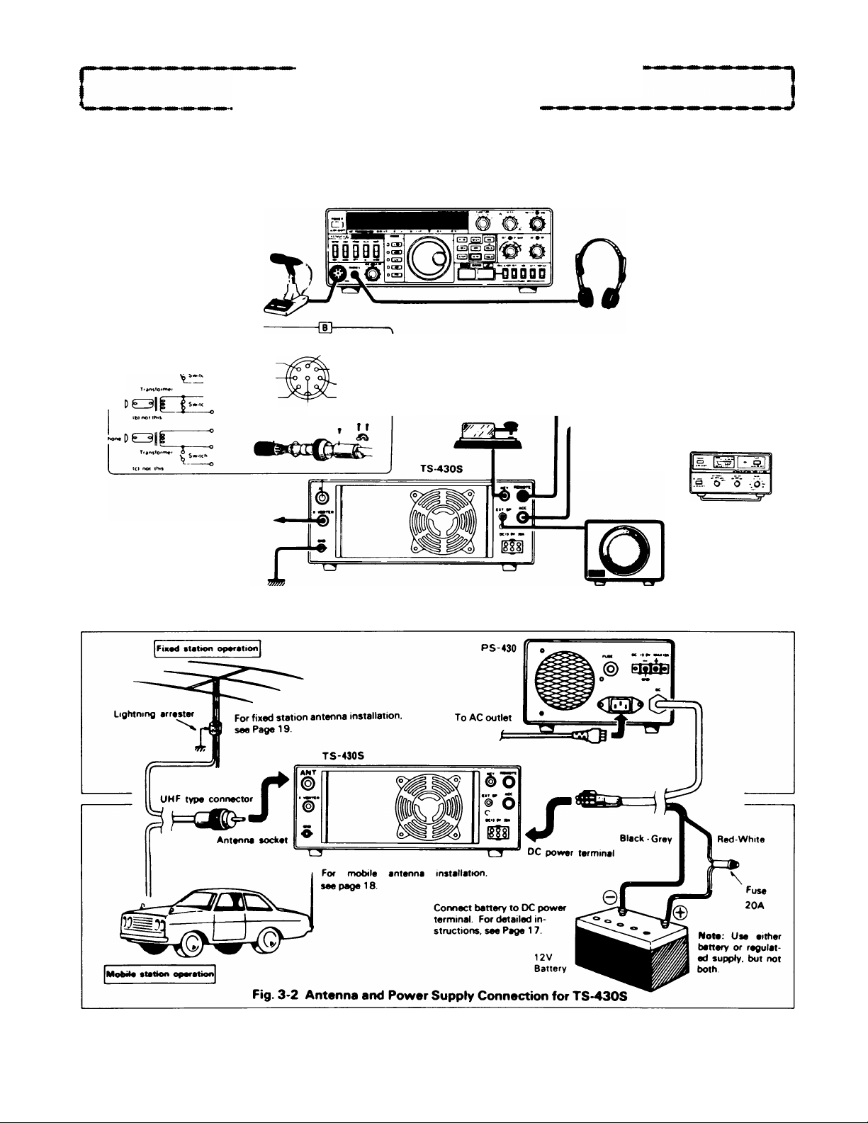
SECTION 3. PREPARATION FOR USE
.INTERCONNECTION
Connect the transceiver as illustrated in Fig. 3-1,3-2.
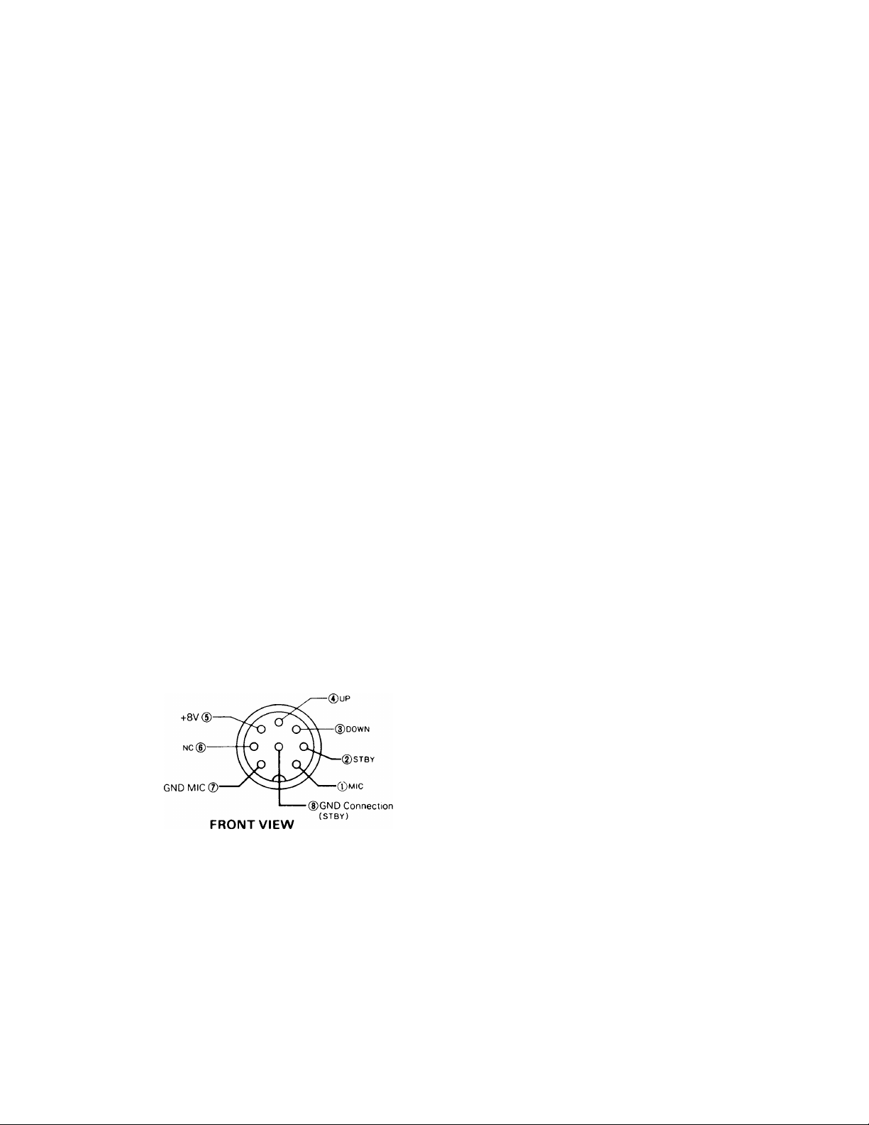
Microphone
Either a low or high impedance
microphone (50013 to 50 Icfi) can
be used. The P.T.T. switch
should be isolated from the mic
circuit (shown in 0)- Use a mi
crophone with a separate switch
and MIC line so both P.T.T. and
VOX are available.
-ra-
View from cord side
HC3|f
(INPUT) ^
GND(MIC)®
GNO terminal
It is recommended that a ground
lead be connected to the GNO
terminal at the rear of the set to
prevent the possibility of electric
shock, TVI and BCI. Use as short
and heavy a lead as possible.
+8V (INPUT)
(D
NCd)
— ® UP
----
® GNDlSTBYl
® DOWN
® STBY
® MIC
Key
For CW operation, connect
your key to the KEY jack at
the rear. Use shielded cable.
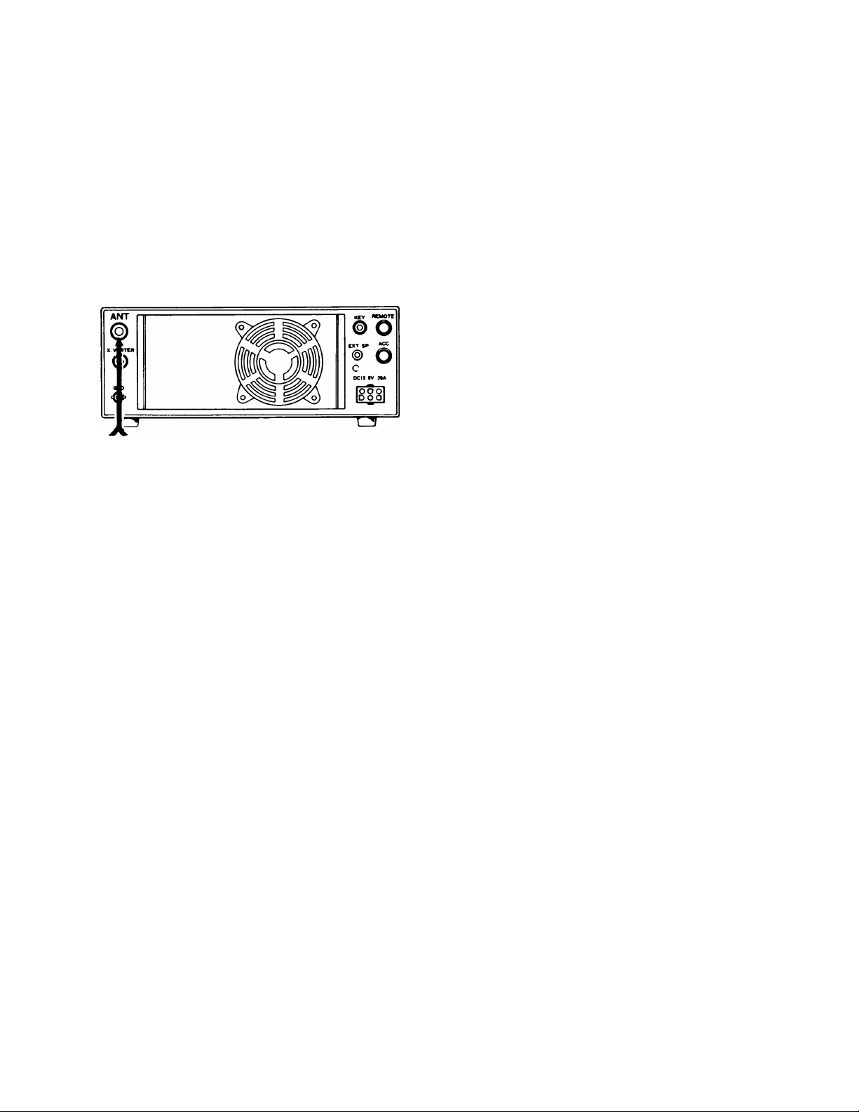
Fig. 3-1 Fixed Station Connection
TS-430S
Headphones
Use headphones of 4 to 160
impedance. The optional
HS-5 or HS-6 headpor>e are
best suited for use with the
TS-430S
Stereo-type headphor>es can
also be used.
REMOTE conitector
External accessories can be con
nected to the TS-430S through
the REMOTE conr>ector. The PTT
terminal can be used for remote
control of transmit/receive opera
tion.
ACCESSORY connector
Accepts automatic antenna
tuner AT-250.
External speaker
Besides the built-in
speaker, an external
speaker can also be
used. Connect to the
rear EXT SP jack us
ing the supplied plug.
Page 6
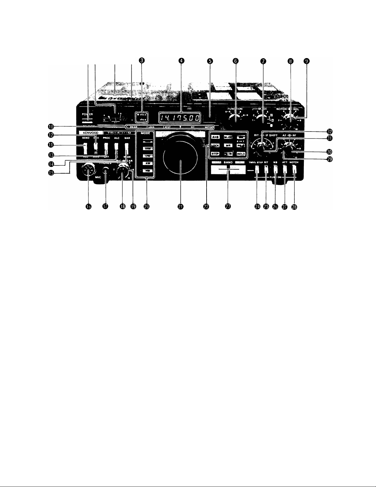
{ SECTION 4. CONTROLS, INDICATORS AND CONNECTORS |
QO ® ®
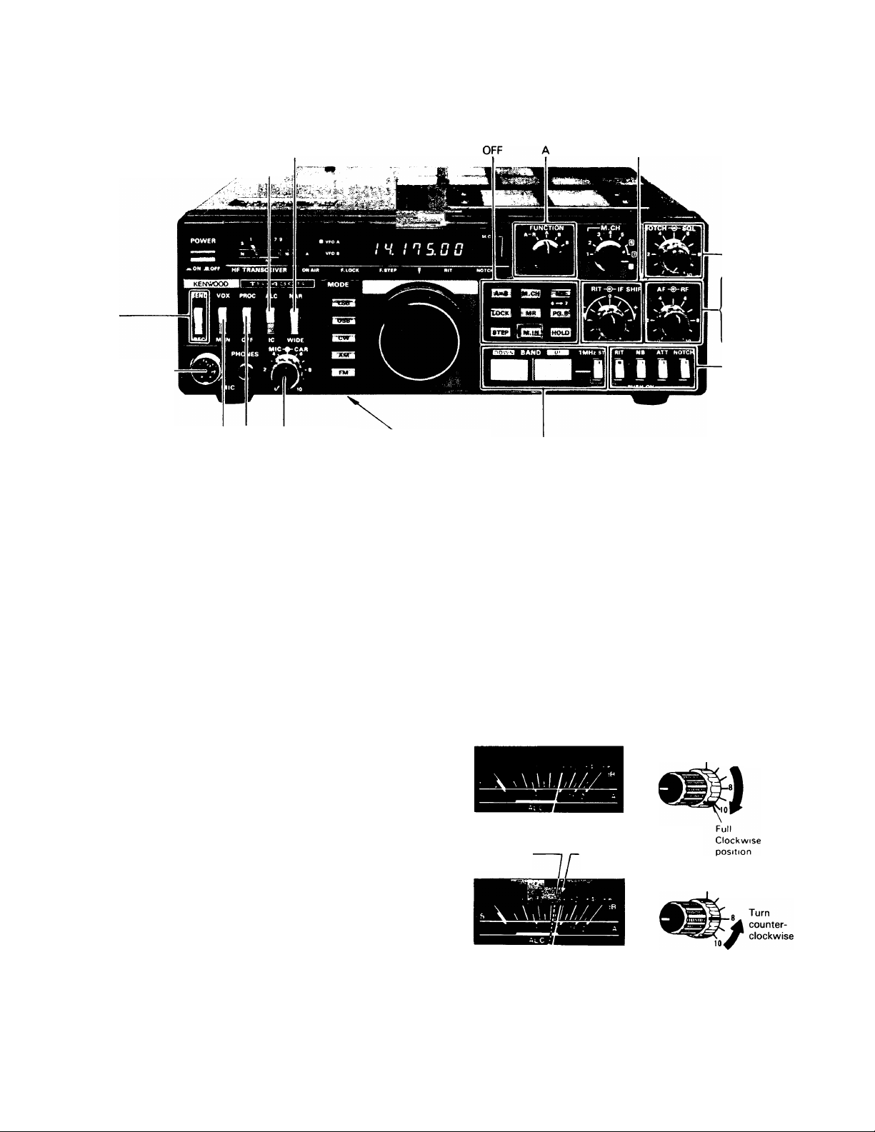
4.1 FRONT AND TOP PANELS
(TS-430S shown)
O POWER switch
This switches the TS-430S ON and OFF.
Before operating the POWER switch, confirm that the VOX
® is off, and the STANDBY switch ® is set to the recep
tion mode (REC).
O METER
The meter has three functions, two being selected by the
METER switch. In receive the meter is automatically an S-
meter showing receive signal strength on a scale of 1 - 9,
+20, +40 and +60 dB. In transmit, the meter shows 1C or
ALC level, depending on METER switch position.
0 VFO indicators
VFO A indicator lights when VFO A is operating. VFO B
indicator lights when VFO B is operating.
O Digital display
The digital display indicates true operating frequency in all
modes to an accuracy of 100 Hz.
0
M.CH (Memory Channel) display
Indicates memory channel 1 - 8 or P, program scan.
0 FUNCTION switch
This selects the VFO which will control receive and trans
mit frequencies. Select position A or B for normal opera
tion. A-R and B-R are used for split frequency or cross
band operation.
A-R: VFO A operates during reception and VFO B during
transmission.
A: VFO A operated, VFO B stands by.
B: VFO B operates, VFO A stands by.
B-R: VFO B operates during reception and VFO A during
transmission.
O MEMORY CH selector
This selects one of the eight memory channels. To write
in a frequency depress the M.IN switch and the displayed
frequency will store in the selected channel. To recall from
a memory channel, select the channel and depress the MR
switch.
0 NOTCH control
Turn the NOTCH switch ® ON to activate the notch filter.
Adjust the notch frequency to null beat (carrier interfer
ence) signals.
0 SQUELCH control
The squelch control is used to eliminate noise during no
signal time. This control may be adjusted clockwise until
the noise disappears (threshold level). The control func
tions for all modes; SSB, AM and CW. In the FM mode,
squelch functions only when the optional FM-430 is in
stalled.
0 Indicators
ON AIR indicator: This lights during transmission mode.
F.LOCK (Frequency lock): Lights when the F.LOCK switch
® is ON, indicating the VFO operating frequency is locked.
F.STEP (Frequency step): Lights when the STEP switch
is ON, indicating a fast VFO tuning rate.
RIT (Receiver Incremental Tuning): Indicates the RIT
switch ® is ON.
NOTCH: Indicates the notch filter is operating and lights
when the NOTCH switch © is ON.
0 STAND-BY switch
This switch selects:
REC: The transceiver is receiving unless the microphone
PTT switch or the VOX circuit is activated.
®
Page 7
SEND: Locks the unit in transmit. Transmission is
locked out (reception only) if the selected transmission
frequency is outside the amateur radio bands, or the
final stage thermal-protects (is deactivated due to ex
cessive heat-sink temperature).
® VOX switch
Turn this switch on to activate the VOX (Voice Operated
Xmit) during SSB, AM or FM operation or to allow semi
break-in CW operation.
PROC (Speech processor) switch
This switch is used during SSB or AM operation. At
switch ON the speech processor will be activated, increas
ing average "talk power".
® METER switch
During transmission, the meter switch determines meter
function. The switch selects between:
ALC - The meter monitors the output of the final stage
power amplifier during transmission. During SSB opera
tion, adjust the MIC control so that the meter pointer is
within the ALC zone. Similarly, adjust the CAR control for
CW operation. ALC does not indicate in the AM or FM
mode.
1C - The meter monitors final stage collector current.
1 2 - 1 9A is normal, 1 7A typical.
NAR/WIDE switch
This switch selects receive IF bandwidths when optional
filters are installed.
The WIDE position provides the same IF bandwidth for
both CW and SSB. For the NARROW position, optional
filters are available for both CW and SSB. In the AM
mode, the SSB filter is on in the narrow position.
MIC (Microphone) connector (8-pin)
Microphone audio input. Frequency UP/DOWN control
and PTT lines are included. The MC-42S or MC-60A mi
crophones (optional) are recommended. MIC connector
pin assignments are shown below.
0 PHONES jack
The headphone jack allows use of 4 - 16 ohm (or greater)
impedance headphones. HS-5 or HS-6 optional head
phones provide optimum results. Stereo-type headphones
can also be used. Headphones will disable the internal or
external speaker.
<D MIC (Microphone gain) control
This control adjusts microphone amplifier gain for SSB
and AM operation. In the SSB mode, adjust for an on-
scale ALC reading at voice peaks. For low power opera
tion, adjust this control below the ALC range. For AM
mode adjustment, see "AM transmission" page 11.
^ CAR (CARRIER LEVEL) CONTROL
This controls carrier level during CW operation. Adjust the
carrier level for an on-scale ALC meter reading. For lowpower operation, adjust this control below the ALC range.
® MODE switches and indicators
These switches are used to select the mode; USB, LSB,
CW, AM or FM (optional). Each indicator lights corre
sponding to the mode.
Tuning Knob
This knob controls the dual digital VFO's which operate in
10 Hz step at 10 kHz turn for normal slow tuning, or with
the STEP switch depressed, at 100 Hz step for fast tun
ing.
® Keyboard
• A = B switch: Depress this switch to equalize the fre
quency and mode of the idle VFO to that of the operat
ing VFO.
• LOCK switch: This electrically locks the VFO fre
quency. When this switch is on, the tuned frequency
does not vary when either the tuning knob or BAND
switch is operated. This is convenient when operating
on the same frequency for extended periods. The RIT
does operate with the LOCK switch on. The F.LOCK in
dicator lights to show operation.
• STEP switch: Used to select the VFO tuning rate.
• M.CH (Memory channel) switch: Used to select a me
mory channel as a fixed frequency. With this switch
ON, the channel number is displayed on the M.CH dis
play 0 .
• MR (Memory recall) switch: Depress to recall a select
ed channel from memory to the VFO for tunable opera
tion.
• M.IN (Memory in) switch: Depress to store the dis
played VFO frequency in to a selected memory channel.
• MS (Memory scan) switch
Depress this switch for memory scan operation.
Only channels with stored data are scanned. Scan rate
is fixed at approximately 1.8 sec./channel.
• PG.S (Program scan) switch
Depress this switch to scan from the frequency stored
in CH 6 to the frequency stored in CH 7. Programmed
Scan Speed is adjustable. However, the presence of a
signal does not stop the scan.
• HOLD (Scan hold) switch
Depress this switch to stop the scan operation. Reset
ting this switch to OFF resumes the scan operation.
® BAND selector switches
Used to select the amateur or frequency band. When the
UP or DOWN switch is pressed, the band changes by one
step.
MHz step switch
When depressed ON, this allows the band switch to raise
or lower the frequency in 1 MHz steps within the trans
ceivers full frequency range. At OFF (out) the Band switch
steps the amateur band.
Page 8
® RIT switch
This push switch turns the RIT (Receiver Incremental Tun
ing) circuit ON and OFF. With the switch depressed, the
circuit is activated and the RIT indicator is illuminated, al
lowing the receive frequency to be shifted by about 1
kFIz independent of the transmit frequency by using the
RIT control. The RIT circuit is turned OFF when the switch
is out.
® NB (Noise Blanker) switch
This switch is used to reduce pulsating type ignition
noises usually emitted from motor vehicles. Power-line,
QRM and atmospheric "white" noise will not operate the
noise blanker.
® RF ATT (Attenuator) switch
With this switch ON, a 20 dB attenuator is inserted in the
antenna circuit, protecting the RF amplifier and mixer from
overload on strong input signals.
o 0 o
© NOTCH switch
This switch controls the NOTCH circuit and indicator.
€) RF GAIN control
This adjusts receiver RF amplifier gain. Turn fully clock
wise for maximum gain and a correct S-meter reading.
0 AF GAIN (Audio Frequency) control
This control adjusts the receiver audio output level,
lume increases as the control is turned clockwise.
0 RIT control
When the RIT switch is ON, this will vary the receive fre
quency by about 1 kHz. When the control is set to the
"0" center position, there is no frequency shift.
® IF SHIFT control
By using this control, the IF crystal filter center frequency
can be shifted about 1 kHz, allowing adjustment of tone
quality, or eliminating interference from adjacent frequen
cies. For normal operation, this control should be set to
the center "0" position (at the detent).
0 VOX controls
VOX GAIN: This controls sensitivity of the VOX (Voice
operated Transmit) circuit. Adjust the gain for consistent
key-over by voice, but not back ground noise.
DELAY control: This controls hold time for VOX, or CW
semi-break-in operation. Adjust to hold the transmitter on
between words, at a normal speech, or keying rate.
ANTI-VOX control
This control is used to adjust the VOX system so that it is
not false tripped by sound from the speaker.
0 PG.SCAN (Program scan) control
This adjusts program scan speed.
Vo-
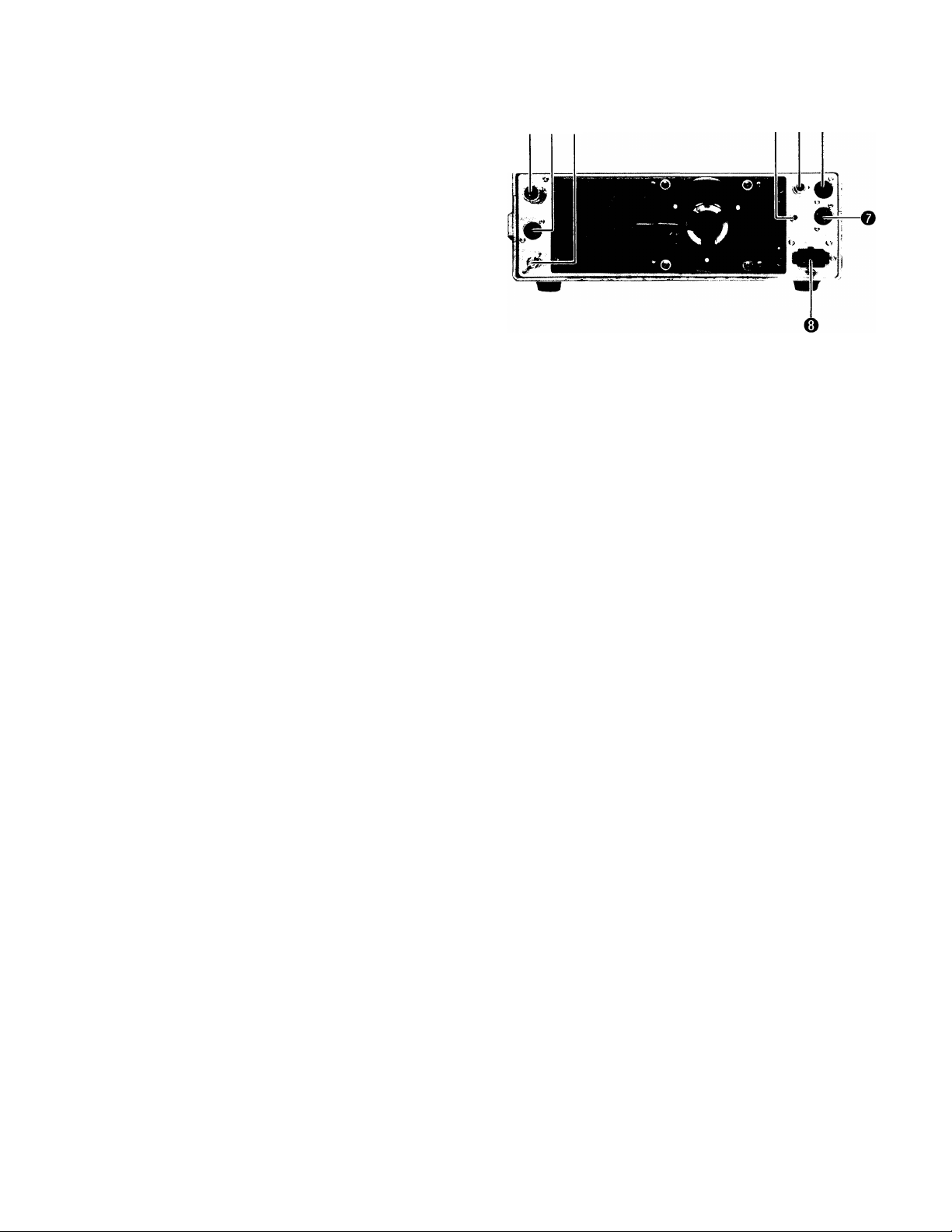
4.2 REAR PANEL
O ANT (Antenna) connector
This UHF connector should be attached to a suitable an
tenna for transmitting and receiving. The antenna cable
should be 50-ohm coax, terminated with a PL-259 con
nector.
0 X. VERTER (transverter) terminal
This 8 Pin DIN connector is used to interface a VHF or
UHF transverter.
See page 23 for pin-outs.
0
GND (Ground) terminal
To prevent electric shock, as well as RFI and BCI, connect
the transceiver to a good earth ground.
O EXT. SP (External speaker) jack
The receiver audio output can be connected through this
jack to an external 4 to 1 6 ohm speaker. The internal
speaker is disconnected when an external speaker is con
nected.
0
CW key Jack
Using shielded line, connect a key to this 1/4" phone jack
for CW operation. Key open-terminal voltage is approxi
mately 9V DC.
0 REMOTE connector
This connector is used to interconnect a linear amplifier or
other accessory item.
0 ACC (Accessory) connector
This connector is used to access the automatic antenna
tuner AT-250. Refer to page 22.
0 DC POWER connector
This is used to connect the DC power supply.
Page 9
SECTION 5. OPERATION
Note: ® denotes transmit mode; (g) denotes receive mode.
REC
® Connect mie
WIDE
®J.'ALG<
OFF Both CAR and MIC '^Select the mode
fully counterclockwise ® Select band
MAN
Fig. 5-1 Initial Control Settings
Centered
Fully counter
clockwise
®
RF; Fully
clockwise
AF: Fully counter
clockwise
OFF
5.1 RECEPTION
5.1.1. RECEPTION
First connect the antenna, microphone and key. Then, set the
controls and switches referring to Fig. 5-1.
Acertain that the TS-430S is ready for operation, then turn the
POWER switch ON. The meter and digital display will illumin
ate, indicating the transceiver is in operation. The transceiver is
fully solid-state, allowing reception as soon as the POWER
switch is switched ON.
Advance the AF GAIN control clockwise until some receiver
noise is heard from the speaker. Turn the main tuning control
so the desired signal can be heard clearly.
5.1.2. RF ATT SWITCH
The input to the receive RF amplifier is attenuated approxi
mately 20 dB, providing distortion-free reception. This feature
may be used in cases of receiver overload, caused either by a
strong local signal, or during weak signal reception when a
strong adjacent signal may blank the receiver.
5.1.3. NB SWITCH
The TS-430S has a sophisticated noise blanker designed to re
duce ignition-type pulse noise. The noise blanker is particularly
important for mobile operation. When necessary, activate the
noise-blanker by depressing the NB switch ON.
5.1.4. RF GAIN CONTROL (Fig. 5-2)
For normal operation, this control should be turned fully clock
wise for maximum sensitivity. Receive sensitivity is reduced by
turning the control counterclockwise.
Adjust the RF GAIN so the S-meter does not show excessive
deflection. This minimizes noise during reception and allows
the S-meter to indicates signal peak (or a little below that
point). Noise is markedly reduced when signal is absent.
S-meter peak point
Signals below
this level are
attenuated
AF GAIN -gb- RF GAIN
S-meter reading
at partial counter
clockwise position
of RF GAIN control
AF GAIN RF GAIN
6
6
Fig. 5-2 RF GAIN Control Operation
Page 10
5.1.5.1. SQUELCH
To eliminate receiver noise at the no-signal condition,
slowly advance the squelch clockwise until the noise just
disappears (threshold point).
The squelch will open and the speaker will operate when a
signal is received. If the signal is weak or fades, readjust
the squelch for consistent reception.
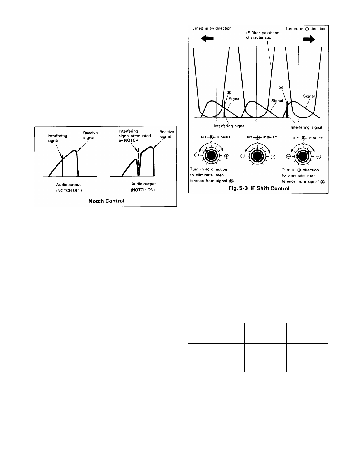
5.1.5.2. NOTCH CONTROL
If a single tone such as a CW signal is superimposed on
the receive signal, turn the NOTCH ON and adjut the
NOTCH control to eliminate or minimize the beat signal. A
beat of approximately 900 Hz can be eliminated at the
center position of the control. The NOTCH is effective bet
ween 350 and 2600 Hz.
5.1.6. RIT CONTROL
By using the RIT (Receiver Incremental Tuning) control, the
receive frequency can be shifted by about ± 1 kHz with
out changing the transmit frequency.
If the frequency of the station you are working changes,
your receive frequency can be reset by turning the RIT
switch ON and adjusting the RIT control. Adjusting the
control clockwise increases the frequency. When first
calling another station, the RIT should be OFF, otherwise
your transmit and receive frequency will not coincide.
5.1.7. IF SHIFT CONTROL
The IF SHIFT control is used to shift the passband of the IF
filter without changing receive frequency. By turning this
control in either direction, the IF passband is shifted as
shown in Fig. 5-3.
The IF SHIFT is effective in eliminating interference when
nearby signals are superimposed on the receive signal dur
ing either SSB or CW operation. IF SHIFT does not oper
ate in the AM or FM modes.
(1) USB Mode (10 MHz and above)
Adjust the IF SHIFT control in the + direction and lower
frequencies are cut. Adjust the control in the - direction
and high frequencies are cut.
(2) LSB Mode (7 MHz and below)
Adjust the control in the + direction and higher frequen
cies are cut. Adjust the control in the - direction and low
frequencies are cut.
(3) CWMode
By using the IF SHIFT in conjunction with the RIT, tone
quality can be adjusted.
5.1.8. NAR-WIDE switch operation
For short to medium distance communication, the WIDE
position may be used for both SSB and CW operatin. For
DX (long distance) communication, the NAR position will
be an advantage in reducing interference.
This feature, in combination with the IF SHIFT control, will
provide outstanding interference rejection. The receive IF
bandwidth is 2.4 kHz in the SSB and CW wide position,
270 or 500 Hz for CW (with optional filters YK-88CN or
YK-88C) and 1.8 kHz for SSB (with optional filter
YK-88SN), in the NAR position.
*ln the AM MODE without an optional filter, both WIDE
NARROW positions are 2.4 kHz. With a YK-88A, Wide is
6 kHz, and Narrow is 2.4 kHz.
*ln transmit bandwidth is automatically WIDE.
PASSBAND WIDTH (-6 dB) kHz
MODE
No optional filter 2.4
YK-88C or CN 2.4
YK-88SN
YK-88A
WIDE
- -
- -
CW
NARROW
500
or 270
SSB
WIDE
NARROW
•
2.4
-
2.4
-
*
-
1.8
-
AM
WIDE
NAR
2.4
-
-
6
NOTE: ------------------------------------------------------------------------ .
1. Without optional filters, there is no SSB or CW recep
tion in the NAR switch position (*).
2. The NAR/WIDE switch does not function in the AM, FM
mode.
3. Without an optional filter, the AM mode bandwidth is
2.4 kHz.
10
Page 11
5.2 TRANSMISSION (Fig. 5-4)
CAUTION:
Before transmitting, be sure to connect an antenna or
dummy load with a VSWR of less than 1.5:1. Never at
tempt to transmit with the antenna terminal left open.
When testing the transmitter, use a 50-ohm dummy load,
rated at greater than 100W (TS-430S). Refer to Fig. 5-1
for initial control settings. When the TS-430S is ready for
transmission, use the following procedures:
----------------------------------------------------
TS-430S
W B
Fig. 5-4 Testing with Dummy Load or
Power Meter
O
o
Power meter
Dummy load
5.2.3 PROC (processor) operation
In DX (long distance) SSB or AM operation, it may be de
sirable to increased talk-power by using the speech pro
cessor.
The speech processor in the TS-430S combines an audio
compression amplifier with changes in ALC time constant
to provide extra audio punch and increases average SSB
output power, while suppressing sideband splatter. To
activate, turn on the PROC switch, and readjust MIC gain.
Operated as described, distortion will be minimal. How
ever, tone quality will be affected. It is therefore advisa
ble to conduct normal operation with the processor dis
abled.
NOTE: ------------------------------------------------------------------------------When a high-output microphone is used, input overload
and distortion may result.
To prevent this, use an attenuator in the microphone cir
cuit as shown below, or connect a 10 - 33ki3 resistor (de
pending on the microphone used) across the microphone
input. (Mic control setting should be approximately 12 o'
clock)
10k — 33 kil (depending on micropone used.)
O
-----
^N^
--------•---------
from microphone
O
---------
The MC-60A microphone is recommended (Microphone
sensitivity: -55 ±3dB for approx. 5 cm distance to the
mic). The MC-60A MIC AMP Switch should be set at the
OUT position.
O
to the MIC connecter
-O
5.2.1 SSB Operation
1. Set the MODE switch to SSB.
2. Meter switch to ALC.
3. Standby switch to SEND.
4. Speak into the microphone and adjust the MIC GAIN for
meter deflection within the ALC zone at signal peaks.
5. For QRP (Low Power) operation, use less MIC GAIN and
consult your external wattmeter for output level.
5.2.2 AM Operation
1. Set the MODE switch to AM and the meter switch to
1C.
2. Place the STANDBY switch to SEND and adjust the
CAR control so the meter registers approximately 2/3
its usual deflection.
3. Speak into the microphone and advance the MIC GAIN
control so the meter deflects only slightly at peaks.
Note that excessive meter deflection indicates overmo
dulation.
4. The PROC may be used to provide a more constant mo
dulation level.
5.2.4 CW Operation
1. Set the MODE switch to CW and the meter switch to
ALC.
2. Set the standby switch to SEND and adjust the CAR
control so the meter deflects within the ALC zone. If a
key is connected, it should be depressed during the ad
justment.
3. For QRP operation, adjust the Carrier Control below the
ALC point.
NOTE: -------------------------------------------------------------------------------Full power operation (more than 5 minutes at ambient
temperature of 25°C, in case of 10 MHz band, more than
30 seconds because of final efficiency), with the key kept
depressed may result in unit trouble. At this time, pay
attention to installation condition as well as ambient tem
perature, and decrease the power or operate the unit after
an interval.
5.2.5 FM Operation (With FM-430 FM unit installed)
1. Place the MODE switch to FM.
2. Place the STANDBY switch to SEND.
3. Speak into the microphone. (In the FM mode, the MIC
GAIN, CAR and meter switches are not used.)
11
Page 12

5.2.6. FINAL STAGE PROTECTION
The TS-430S features a VSWR protection circuit to pro
tect the final-amplifier transistors.
Three different protection circuits are used.
1. The final-stage transistors are protected by detecting
VSWR of the antenna system and automatically low
ering transmitter output power if the VSWR is too
high.
2. When the heat-sink temperature rises, a detection cir
cuit activates a cooling fan. Under normal conditions,
this cooling fan sufficiently cools the heat sink.
3. The heat-sink temperature could rise abnormally dur
ing long transmissions, if the area adjacent to the
heat-sink is blocked. In this case, the transmission is
inhibited until the heat-sink cools to the proper tem
perature.
NOTES: ------------------------------------------------------------------------
1. If transmitter output decreases due to activation of the
protection circuit caused by high VSWR, carefully re
check and retune the antenna system.
2. When the cooling fan starts to operate, determine that
adequate air flow is possible in the heat-sink area.
• Operation of the Cooling Fan
The cooling fan operates when the heat-sink temperature
rises to approximately 50°C (122°f) and ceases to operate
when the temperature decreases to normal, approximately
40°C (104°F). The heat-sink is made of die-cast aluminum
and is actually the rear panel. It must be kept clear of sur
rounding objects to allow heat to dissipate easily.
The cooling fan is designed to operate when the heat-sink
temperature is at a specific level, regardless of whether
the unit is in transmit or receive mode.
5.2.7. MIC GAIN CONTROL (Fig. 5-5)
This control adjusts the microphone input level. When us
ing the TS-430S in a voice mode, connect a microphone
and set the STANDBY switch to SEND (an antenna or
dummy load must be connected).
For SSB operation, set the meter switch to ALC and speak
into the microphone. Adjust the MIC GAIN control so the
meter does not deflect out of the ALC zone at signal
peaks.
The TS-430S accepts either a low or high impedance mic
rophone (500 i3to 50 kO\. When using a low impedance
microphone (500 Q the MIC GAIN control should be ad
vanced slightly higher than when a high impedance micro
phone is used, while observing the ALC meter.
•
• ALC (Automatic Level Control)
The ALC monitors the transmitter final stage output to
minimize distortion in your transmitted signal. It automati
cally adjusts output to an optimum level.
Pointer should not deflect beyond ALC zone at signal peaks.
/
3 5 7 9 +20 -1-40 +60
Fig. 5-5 ALC Adjustment
5.3 VOX OPERATION
5.3.1. VOX SWITCH
vox (voice operated transmit) is used to switch the
TS-430S into transmit mode by your voice. Place the
VOX switch ON and speak into the microphone. The
transceiver automatically switches to transmit mode (the
MIC control should be adjusted in advance as explained in
Item 5.2.7). Both the SEND switch and the MIC P.T.T.
switch are left in the REC position.
5.3.2. VOX GAIN CONTROL
This adjusts the VOX circuit sensitivity. Speak into the mi
crophone at a normal voice level and adjust the control.
Increased sensitivity allows transmission with a lower
voice level. Transceiver operating condition (receive or
transmit) can be checked by the ON AIR LED.
Note that if the control is advanced too far, the VOX circuit
may be "tripped" by ambient noise.
5.3.3. ANTI-VOX CONTROL
This prevents the VOX circuit from being false-tripped by
sound from the speaker.
Adjust the control so the VOX will not operate at the de
sired speaker volume level.
12
Page 13

5.3.4. VOX DELAY CONTROL
This control adjusts the VOX circuit transmit hold time. If
the hold time is too short, the transceiver will return to re
ceive mode as soon as you stop talking into the micro
phone. This can be eliminated by advancing the control.
Adjust the control for comfortable operation at a normal
rate of speech.
5.6 CW OPERATION
For CW operation, your transmit frequency should be
"zero-beat" to the transmit frequency of the station you
are contacting. This also allows your contact to receive
your signal without having to retune his receiver. Tuning
methods are detailed in the following paragraphs.
5.4 SEMI-BREAK-IN OPERATION
The TS-430S has a built-in side-tone oscillator which,
used in conjunction with the VOX circuit, allows semi
break-in operation, besides the conventional (SEND switch
controlled) CW operation. During semi-break-in operation,
the transceiver is placed in transmit mode when the key is
depressed, and returns to receive mode when the key is
released. The VOX circuit is activated by the side-tone.
For semi-break-in operation, set the VOX switch ON and
the MODE switch to CW. Adjust the VOX GAIN to insure
that the transceiver is set in transmit mode whenever the
key is depressed. Also, adjust the VOX DELAY for the de
sired hold time.
ANTI VOX adjustment is not required.
— NOTES:--------------------------------------------------------------------
In VOX operation (semi-break-in) with VFO A/B or
transmission/reception memory (CH8), the following
combination is not possible by the circuit configur
ation.
BX TX
ANY VOICE MODE
CW
CW (Semi-break-in)
LSB, USB (VOX)
Any voice mode
VOX
5.5 OPERATION WITH A LINEAR
AMPLIFIER
The remote connector on the rear panel provides for inter
connection with an amplifier. See the amplifier instruction
manual to determine whether the linear requires a normal
ly opened or normally closed (during receive) relay con
tact. Connect the amplifier control line to either pin 5
(N.C.) or pin 4 (N.O. during receive). Connect the Ground
(Shield) of the Control Line to Pin 2. Connect amplifier
ALC to pin 6 of the remote connector. The TS-430S out
put is quite adequate to drive most amplifiers to full rated
output.
For full details, see section 6.8, page 22.
Your frequency
Receiver carrier frequency ^.,^1
(BFO)
1
1
1
1
1
Displayed frequency
T ransmit-Receive frequency
(Displayed frequency)
800Hz
Beat note
Fig. 5-6 Tuning for CW Operation
MOTE: --------------------------------------------------------------------------------
1. In CW mode, transmit frequency is displayed when
both transmitting or receiving.
2. During CW operation, operating the BAND switch
differs from other modes; for example, pressing the UP
(BAND) switch at display frequency 14,000.0 shows as
follows.
14,000.0 ^ 14,500.0 ^ 18,500.0 ....->UP
10,500.0 ^ 14,500.0
5.6.1. OPERATION WITHOUT AN OPTIONAL
CW FILTER
Set the IF SHIFT control to its center position and the BIT
switch OFF. Adjust the main tuning control for an 800-Hz
beat note and your transmit frequency will then coincide
with that of your contact station ("zero-beat"). During re
ception, the side-tone monitor is activated by pressing
down the key (VOX OFF). In this case, listen to the sidetone superimposed on the receive signal and adjust the
main tuning for similar side-tone and incoming CW audio
tone. By so doing, transmit frequencies will coincide.
You may now adjust the BIT for a pitch which suits your
preference. If interference is encountered, adjust the IF
SHIFT. For more convenient and effective CW operation,
use of the optional YK-88C or YK-88CN CW crystal filter
is recommended.
DOWN
13
Page 14

5.6.2. OPERATION WITH A CW FILTER
Set the IF SHIFT to its center position and the RIT to OFF.
Adjust the main tuning control for maximum deflection of
the S-meter. Receive signal pitch will be about 800 Hz, in
dicating correct tuning.
5.6.3. KEY CONNECTION
Your key should be connected as illustrated in Fig. 5-7.
When using an electronic keyer, make sure that polarity is
set for positive. Always use shielded line from the key to
transceiver.
5.7 Keyboard function
Brings the idle VFO frequency and mode
to that of the active VFO.
Locks the operating frequency.
Switches to RAPID frequency step for VFO
step tuning or program scanning. Step is
10 Hz in the normal position, and 100 Hz
in the ON position.
Inputs both frequency and mode into a
selected memory channel (CH's 1-8).
• Erasing an unwanted frequency from memory
Unwanted memory content can be erased.
1. Depress the M.CH switch, and select the channel to be
erased with the M.CH switch.
2. Simultaneously depress the BAND switch (either UP or
DOWN), and the M.IN switch.
3. The display will clear, and only the decimal points will
display. All mode indicators will remain off.
Depress to recall a memory channel. Se
lect the channel with the M.CH switch.
Depress to scan the memory channels.
Scans the range between CH 6 fre
quency and CH 7 frequency.
Holds scan. During program scan hold,
frequency can be tuned with the VFO
control and the mode can be switched.
When this switch is depressed, the chan
nel selected by the M.CH switch is re
called to the VFO for tunable operation.
The mode can also be controlled when
recalled by the MR switch.
® Depress the M.CH switch, and place the M.CH switch
to the unwanted memory channel.
14
Page 15

• M.CH (Memory channel) operation
The TS-430S has eight memory channels. The memory
permits input of both frequency and mode, and this data
will be permanently retained (by the built-in lithium bat
tery).
1. The M.CH switch selects the desired channel from CH
1-8.
2. When the M.IN switch is depressed, a "beep" sounds,
indicating memory input.
3. There are two recall modes for memory channel con
tents.
* Depress the M.CH switch. Any one of eight channels
can be selected by the M.CH switch as a fixed (nontunable) frequency and mode.
* Depress the MR switch. The channel designated by
the M.CH switch is recalled to the VFO for tunable oper
ation. The memory contents are not changed.
These switches are for
recalling memory.
• Memory scan operation
1. Input frequencies and modes to be scanned into the
memory channels.
2. Depress the MS switch. The channel number and fre
quency of each occupied channel is displayed. Scan in
terval is approximately 1.8 seconds per channel.
3. When the desired traffic is received during scan, de
press the HOLD switch.
4. Scan will resume by releasing the HOLD switch.
NOTES: ------------------------------------------------------------------------------
1. The channel eight transmit frequency is not scanned.
2. When memories are empty, is displayed and there is
no scan.
3. Scan is held by transmitting, and resumes when the
transceiver returns to the receive mode.
(2) Depress to initiate memory scan.
15
Page 16

Program scan operation
1. Program the scanning frequency range.
2. Input the lower (or upper) frequency limit and mode into
CH 6 (using the M.IN switch). Then, input the upper (or
lower) frequency limit into CH7.
3. Depress the PG.S switch to initiate scan. The letter P
will display during program scan.
4. The scan speed is adjustable using the speed control on
the top panel, along with the STEP switch. Select the
scan speed appropriate for the selected frequency and
mode.
5. When the desired station is received and that frequency
is to be held, depress the HOLD switch. Then, adjust
the VFO for best tuning. During hold, the mode may be
temporarily changed. When Hold is released, the mode
will revert to the original programmed mode setting
after one scan cycle.
6. After the CH 7 upper (or lower) frequency limit has been
reached, a "beep" sounds and the scan repeats from
the CH 6 frequency.
NOTE: --------------------------------------------------------------------------------
1. Program scan is from CH 6 to CH 7, only.
2. During scan, only the CH 6 mode is used.
3. During scan or scan hold, a frequency can be stored
into a memory channel selected by the M.CH switch by
depressing the M.IN switch.
4. When the scan is on and the STEP switch is depressed,
the step is 100 Hz.
5. When CH 6 and CH 7 are empty, there can be no scan.
6. Scanning is stopped during transmit and resumed after
return to the receive mode.
• Memory CH 8 reception and transmission operation
1. Place the M.CH switch to "8".
2. Input the reception frequency and mode using the M.IN
switch.
3. The usual data entry "beep" is emitted as a pulse train.
Input the transmission frequency (and mode).
4. The "beep" ceases.
5. Depress the M.CH switch. "Split" frequency operation
(transmission and reception on different frequencies
are programmed into CH 8.)
NOTE: --------------------------------------------------------------------------------
1. Different modes and/or bands can also be programmed
for transmission and reception.
2. If the M.IN switch is depressed twice in succession, this
memory can be used as an ordinary memory, now hav
ing the same frequency for both transmission and re
ception.
(D Pressing this switch TWICE allows
transmission and reception on different
frequencies.
16
Page 17

5.8 MOBILE OPERATION
Being compact in design, this transceiver is ideal for mo
bile operation. Satisfactory mobile operation is achieved
through proper power and antenna connection, and
thoughtful transceiver installation and adjustment.
5.8.1. TS-430S INSTALLATION
Secure the TS-430S under the dashboard using an option
al MB-430 mounting bracket as shown in fig. 5-8. As an
alternative, use strapping, making sure that the TS-430S
will not slip out of place while operating the vehicle.
NOTES;-------------------------------------------------------------------------------
1. Do not install the TS-430S near the heater outlet.
2. Allow sufficient space behind the TS-430S to ensure
proper ventilation.
5.8.2. CONNECTING THE POWER CABLE
When connecting or disconnecting the power cable to or
from the power connector, be sure that the power switch
is always in the "OFF" position. Observe polarity of the ca
ble. The TS-430S operates on 13.8V DC, negative
ground. Battery polarity must be correct. The power cord
is color coded.:
17
Page 18

POWER CABLE
CAUTION: Observe battery polarity.
TS-430S
Red and White +
Black and gray -
Connect the TS-430S power cable to the battery termin
als, with consideration to current requirements and noise
prevention. The maximum current drawn by the TS-430S
reaches to between 18 and 20A when transmitting.
Therefore, the cable should be made as short as possible,
using the specified fuse. Also, determine that the power
system of the car (including the battery and generator or
alternator) will handle the increased load of the TS-430S.
Route battery and ANTENNA leads away from all high vol
tage secondary circuits to prevent ignition noise interfer
ence.
5.8.3. MOBILE ANTENNA
(1) Antenna Installation
Use a sturdy mount for the mobile antenna since HF an
tennas are larger (and have more wind load) and are hea
vier than VHF antennas. A bumper mount is recommend
ed for general use. The ground side of the mount must be
well grounded to the car body, since the body itself func
tions as the ground plane for the mobile antenna. (Refer to
Fig. 5-8)
NOTES: ------------------------------------------------------------------------------
1. Some cars have plastic bumpers. For such cars, ground
the antenna mount to the body.
2. When tuning a newly installed antenna, use the follow
ing procedure:
• Turn the CAR control fully counter-clockwise for
minimum transmit power.
• With the transceiver in transmit mode, raise transmit
power output slowly by rotating the CAR control
clockwise. The antenna should be adjusted with
minimum power.
• Transmitting with full power is recommended only
after the antenna has been adjusted for a VSWR be
low 1.5:1.
3. Antenna installation is critical for successful mobile
operation. For further information refer to THE RADIO
AMATEUR'S HANDBOOK, RADIO HANDBOOK, or
other texts.
(2) Coaxial Cable Connection
When the antenna is mounted on the vehicles bumper, the
coaxial cable from the antenna can be routed through a
drain hole in the trunk. When the antenna is roof mounted
pass the cable between the body and door. Leave a drip-
loop at the lowest point in the cable before entry into the
vehicle to prevent water from entering the car.
(3) Antenna Adjustment
Some mobile antennas are not designed at 50-ohm impe
dance. In this case, impedance matching between the an
tenna and the coaxial cable
achieved by using an antenna matching device or coupler.
The antenna to be used should first be checked with a dip
meter to insure that it is designed for your operating band,
then the impedance matching should be checked with an
SWR meter. (See Fig. 5-9)
The VSWR should preferably be less than 1.5:1 for satis
factory operation. For antenna adjustment refer to the an
tenna instruction manual.
5.8.4. NOISE REDUCTION
In motor vehicles, noise is generated by the ignition sys
tem. Other sources of noise include the wiper and heater
motors.
Although the TS-430S is equipped with a noise blanker to
minimize ignition noise, it is imperative that some preven
tive measures be taken to reduce the noise to the lowest
possible level.
(1) Antenna location Selection
Since ignition noise is generated by the vehicles engine,
the antenna must be installed as far from the engine as
possible.
(2) Antenna Matching
In general, mobile antennas have a lower impedance than
the 50-ohm coaxial cable used to feed them, resulting in a
mismatch between the antenna and the coax. Such trou
ble can be eliminated by using an antenna tuner between
the TS-430S and the coaxial cable.
(50Q) is required. This can be
18
Page 19

O Matching Circuit Examples
o
-------
INPUT 3^
O
----i--------
(3) Bonding
The component parts of motor vehicles, such as the en
gine, transmission, muffler system, accelerator, etc., are
coupled to one another at DC and low frequencies, but are
isolated at high frequencies. By connecting these parts
using heavy, braided ground straps, ignition noise can be
reduced. This connection is called "bonding".
(4) Use ignition Suppressor Cable or Suppressor Spark
Plugs
Noise can be reduced by using spark plugs with internal
resistors, or resistive suppressor ignition cable.
(5) Battery Power Connection
It is recommended that battery power be suppilied directly
to the TS-430S from the battery terminals.
CAUTION ---------------------------------------------------------------------------Disconnect the TS-430S before jump-starting or before
charging the battery.
(6) Battery Capacity
The power system of a motor vehicle is comprised of a
battery and an alternator (which generates power while
the engine is running) to supply current to loads or to
charge the battery.
Since the transceiver draws high current during transmit,
care should be excersised so the power system is not
overloaded. When using the transceiver, the following
points should be observed from the viewpoint of battery
maintenance:
1. Turn the transceiver OFF when the lights, heater, wip
ers and other high-draw accessories are used.
2. Avoid transceiver operation when the engine is not run
ning.
3. If necessary, use an ammeter and/or a voltmeter to
check battery condition.
OUT PUT
Fig. 5-10 Matching Circuits
O—(-
INPUT I
o
----
L
OUTPUT
3^
5.9 FIXED STATION OPERATION
5.9.1. Power
The TS-430S requires more than 18A at 13.8 VDC when
transmitting at full power. Use the model PS-430 power
supply for fixed stations.
For HF fixed-station operation, an antenna specifically de
signed for amateur operation is recommended. Antenna
types include wire antennas, verticals, rotary beams, and
other antenna types. HF antennas are quite large and
must be installed to withstand strong wind, heavy rain,
etc.
Any antenna used with the TS-430S should be of 50-ohm
impedance and should be connected using an appropriate
coaxial cable such as RG-8/U.
Impedance matching is important. Impedance mismatch
ing will result in a high VSWR and power loss, or can
cause unwanted harmonic radiation and interference (TVI,
BCD.
The impedance match can be checked with an SWR
meter. Generally, satisfactory operation is assured when
the VSWR (Voltage Standing Wave Ratio) is less than
1.5: 1.
A rotary beam antenna is very effective for DX operation in
the 14, 21 and 28 MHz bands. (Fig. 5-11)
NOTE: -------------------------------------------------------------------------------Protect your equipment - use a lightning arrestor.
19
Page 20

SECTION 6. ADDITIONAL INFORMATION
6.1 GENERAL INFORMATION
Your TS-430S has been factory aligned and tested to spe
cification before shipment. Under normal circumstances,
the transceiver will operate in accordance with these oper
ating instructions.
If your transceiver fails to work, contact the authorized
dealer from whom you purchased it for quick, reliable re
pair. All adjustable trimmers and coils in your transceiver
were preset at the factory and should only be readjusted
by a qualified technician with proper thest equipment.
Attempting service or alignment without factory authori
zation can void the transceiver's warranty.
6.2 INSTALLING THE OPTIONAL
FILTERS
1. Remove the power connector from the radio.
2. Using a #2 philips screwdriver, remove the top cover
(8 screws). Be careful of the VOX controls, and the
speaker lead, which may be unplugged.
3. Loosen the two side screws and remove the 2 screws
securing the IF unit bracket. Swing the bracket up
slightly to access and remove the two heat sink
screws. Swing the assembly down.
4. Remove 7 screws from the IF unit. Switch the board
forward. Protect the top of the front panel from
scratching.
5. Using a 45W (or less) soldering pencil, clear the 6
holes for the filter, if they are filled with solder. When
installing an AM filter, first remove R16 on the IF unit,
and cut the R-129 lead on the Control unit.
6. There is no polarity to the filter. Install the filter into
its position on the IF unit. Solder the 2 mounting tabs,
and the 4 input and output pins to the circuit board.
Solder sparingly, and heat the connections only long
enough to insure a good solder joint. Don't overheat
the filter or circuit board.
7. Carefully inspect your soldering. Be certain that all
pins are actually soldered, and that you have not sol
dered across any spots on the board or between any
of the pins on the filter. Clip the pins flush to the
board.
8. Replace the IF unit in its place. Make certain no wires
will be pinched underneath the board. Replace the 7
screws for the board, plus the two heat sink screws.
Tighten the 2 side screws and replace the 2 rear
bracket screws, (See that the wire harness does not
interfere with the PG scan speed control).
9. Move the connection as illustrated when an AM filter
is installed.
10. Reconnect the speaker lead, and reinstall the top
cover.
11. Apply power and verify your work. Filter installation is
now complete.
20
Page 21

CONNECTION OF FM-430 CONNECTIORS
FM-430
connector No.
(1)
(2)
(3)
(4)
Switch unit
Unit and TS-430 connector No.
Switch unit (X41 -1470-00)
.......................
19
RF unit (X44-1 510-00).............................20
IF unit (X48-1370-00)
...............................
24
RF unit (X44-1 510-00)............................. 6
TS-430 top view
6.3 OPTIONAL FM-430 INSTALLATION
1. Remove the transceiver top covers and unplug
the speaker lead.
2. Mount the FM-430 on the top right side of the trans
ceiver with 6 screws.
3. Connect the FM-430 harness to the transceiver as fol
lows:
* Connect the leads from connector (1) to connector
(19) of the Switch unit (X41 -1470-00).
* Connect the leads from connector (3) to connector
(24) of the IF unit (X48-1370-00).
* Arrange the leads from connectors (2) and (4) on the
bottom of the transceiver to pass along the side of the
Switch unit. Connect the leads from connector (2) to
connector (20) of the RF unit (X44-1510-00). Con
nect the leads from connector (4) to connector (6) of
the RF unit.
4. Tie the leads as illustrated using the supplied vinyl ties.
5. Reinstall the bottom cover, reconnect the speaker lead,
and reinstall the top cover.
TS-430 bottom view
Fig. 6-5 FM-430 Installation
21
Page 22

6.4 HOW THE TX FINAL TRANSISTORS
ARE PROTECTED
Final transistor protection is provided by sampling the re
flected power. As the reflected power is increased (higher
SWR) transmitter drive is reduced, thus decreasing input
to the final transistors. This in turn reduces collector loss,
protecting the final transistors.
6.5 OPTIONAL 10Hz DISPLAY
RESOLUTION
If you would like 10Hz instead of the supplied 100 Hz dis
play resolution, cut the jumper as shown on the Control
unit.
6.7 OPERATION WITH A LINEAR
AMPLIFIER
Operation with a linear amplifier.
TS—430S internal wiring.
Pin 6 ALC input
Connector Metal Shell is Ground
Pin 2, Relay Common
Pin 4, Relay N.O.
Use shielded line for both ALC and RL (control line).
Initial linear amplifier tune-up should be perfomed with the
exciter at 50% power, to reduce wear-and-tear on both the
linear, and the exciter. Use of a dummy load is strongly
suggested, since the bands are already sufficiently crowd.
The TS-430S may be operated with any conventional lin
ear amplifier which will accept up to approximately 100
watts RF drive, has a low currrent DC operated keying cir
cuit, and returns approximately -8
justable) back to the exciter.
----------------
10 V DC ALC (ad
6.6 PHONE PATCH OPERATION
In an area where phone patch is legal,the PC-1 A Phone
Patch may be used with the TS-430S. Recommended set
ting are:
PC-1A RXGain 4 TS-430S VOX Gain 1
TX Gain 4
Null as necessary Mic Gain 5
Most other phone patches will work satisfactorily without
any modification to the radio, requiring only an external
speaker connection, and that the Mic line be run through
the patch.
For those operators who desire a Patch input similar to the
TS-930S, TS-520SE or TS-820S, an input connection and
terminal must be added at the Mic input preamp circuit.
Use a 100-Ki2 resistor in series, with a 10-ki2 to ground
on the input side of the 100-ki2 resistor. Use shielded line,
and connect as follows:
On the IF unit X48-1 370-00 install the fixed divider at the
junction of R161 10k, C94 lOOpf, and C93 1/^F (input of
Q34). Add an RCA jack at the empty rear panel opening or
use remote pins 7 and Gnd for input.
AF Gain 4
ANTI VOX Max
TS-430 Internal Wiring
View from code
K ^
Fig. 6-7 REMOTE connector
PIN
1 Speaker output
2
3
4
FUNCTION
Relay common
PTT line 7
Relay N.O
REMOTE connector
PIN
5
6
FUNCTION
Relay N.C
ALC input
ALC threshould level
approx. -6V
Not used
22
Page 23

6.8 ACC Connector Data
Data output connector to control the AT-250.
ACC connector output
No.
Freq. bano\^
[MHzl
0.15- 0.4999 0
0.5 - 1.5999 0
1.6 - 2.4999 0 0 1
2.5 - 3.9999
4.0 - 6.4999
6.5 - 7.4999
7.5 -10.4999
10.5 -15.9999 0 1 1 1
16.0 -22.9999 1
23.0 -29.9999 1
Note:
ACC connector wiring
No. 2 BDNo. 4
0
0
0 1
0 1 1
Band output data is TTL level.
0 = Low
1 = high
No. 1 BBNo. 7
BC
0
0 0
0 0
1 1
0
1
0 0
0
0
0 0
0 0 1
BA
1
0
1
0
Frequency band
IMHz]
0.15- 1.5999
1.6 - 1.9999 0
2.0 - 2.9999
3.0 - 3.9999 0
4.0 - 6.8999
6.9 - 7.4999
7.5 -13.8999
13.9 -14.9999
15.0 -20.8999
20.9 -21.9999
22.0 -27.8999
27.9 -29.9999 0
No. 5
WRC
Pin
6.11 FRONT BAIL
The transceiver can be elevated for operating convenience
by extending the bail.
6.12 OPERATION WITH A SECOND
RECEIVER
1
1
1
0
1
0
1
0
1
Use the XVRTR port and an 8 Pin DIN Plug, Part
E07-0851-05.
Pin 8 HF Ant output from the TS-430S
Pin 5 RX Ant input
Pin3 GND
Pin 2 RL control, 12V DC in TX
Connect pins 8 and 5 together and through a short length
of 50i2 coax to your second receiver Ant input.
Use pin 2 to mute the second receiver in TX.
6.13 OPERATION WITH A SEPARATE
RECEIVER ANTENNA
Use the XVRTR port and an 8 Pin DIN Plug, Part
E07-0851-05
Pin 8 HF Ant output from the TS-430S
Pin 5 RX Ant input
Pin 3 GND
Either wire your extra antenna to pin 5 and ground, and
use the DIN plug as the connect/disconnect, or wire pins 8
and 5 and the external antenna through a SPDT switch.
6.9 CHART AND CONNECTION FOR
X. VERTER
FILTER UNIT
6.10 SSTV or AFSK operation
The TS-430S will adapt to slow scan television or AFSK
RTTY operation. For SSTV, the only cabling required are
connections between the transceiver microphone input
and the camera output, and between the speaker output
and the monitor input.
When transmitting, adjust the transmitter output so that
final input power is less than approximately 100 W, or for
approximately 1/2 of normal output power. For AFSK
operation, connect the T.U. output to the microphone in
put, and speaker output to the T.U. inpunt.
6.14 OPERATION AS A SECOND
RECEIVER
Use the REMOTE Connector. Connect Pin 3 (PTT line)
(and Pin 2, GROUND) to your XMTR control output, to
ground Pin 3 in TX. Feed the antenna through the primary
transmitter or transceiver antenna relay.
6.15 ADJUSTMENTS
1. S Meter Zero is VR2 on the IF unit.
2. S meter S-9 calibration is VR3 on the IF, set with 50//V
input at 14.1 75 MHz.
3. "Beeper" audio level is VR6 on the IF unit.
4. CW Sidetone level is VR10 on the IF unit.
5. VFO dial drag (torque) is adjustable from the small slot
ted screw accessed through the bottom cover, directly
under the VFO.
CAUTION;
The supply voltage (13.8V) always flows at the final tran
sistor collector of the TS-430 independently of the ON/
OFF position of the Power switch.
Please be sure to unplug the power cable before removing
the shield cover of the final unit.
---------------------------------------------------------------------------
23
Page 24

SECTION 7. TROUBLE SHOOTING
j
The problems described in this table are failures caused in
general by improper operation or connection of the trans
ceiver, not by defective components.
TRANSMITTER AND RECEIVER CIRCUITS
SYMPTOMS CAUSE
Pilot lights do not light and there is no
receiver noise when the POWER switch
is turned on.
1. Power cord disconnected or AC power OFF.
2. Loose power connector.
3. Blown fuse.
4. PS-430 POWER switch OFF.
RECEIVER SECTION
No signals received with antenna con
nected.
S-meter deflects without signals.
SSB signal unintelligible.
SSB received signal is high or low cut.
Frequency remains the same when
RIT control is adjusted
No output. Standby switch not in transmit position. CAR
No SSB output.
FMing in sideband operation.
vox circuit inoperative
vox operates by sound from speaker.
VOX circuit releases between words or
holds too long.
Signal reports of distortion
Mic or radio chassis is "hot" during TX.
Poor audio in SSB
Standby or microphone PTT switch is in transmit
position.
1. Power supply voltage is too low.
2. RF gain is too low.
Wrong sideband.
IF SHIFT is out of adjustment.
RIT switch is OFF.
or MIC control in minimum position.
1. MIC plug loose.
2. MIC control in minimum position.
Unstable or insufficient Power Supply.
1. VOX control in minimum position.
2. VOX switch in MAN position.
ANTI VOX setting incorrect.
VOX time hold control requires adjustment.
Too much microphone gain.
Excess RF in the shack. No earth ground, poor
ground, or antenna is too close to the radio.
TX-feedbackExcess RF in the shack.
There is a separate Service Manual for repair of the Trans
ceiver.
REMEDY
1. Connect power cord.
Turn AC power ON.
2. Reconnect.
3. Replace fuse (If fuse blows again, contact service
station.)
4. Turn ON the PS-430 power switch.
Place switch in receive position.
1. Adjust voltage to 13.8V DC (12 ~ 16V DC).
Reset voltage selector to correct local AC line
voltage (PS-430).
2. Turn RF GAIN control fully clockwise.
Set MODE switch to alternate SSB position.
Set to the center position (click).
Depress RIT switch ON.
Turn CAR or MIC clockwise.
1. Reconnect.
2. Turn MIC control clockwise.
Adjust voltage to 13.8V DC (12 ~ 16V DC).
Reset voltage selector ro correct local AC line
voltage (PS-430).
1. Turn VOX control clockwise.
2. Set VOX switch to VOX.
Turn ANTI VOX control clockwise.
Adjust delay control.
Reduce MIC control.
1. ANT too close to X CVR.
2. Poor mic GND.
3. Poor or excess length GND less.
24
Page 25

SECTIONS. OPTIONAL ACCESSORIES
1
..J
The following optional accessories are available for use
with the TS-430S.
■ SP-430 EXTERNAL SPEAKER
The SP-430 is an external speaker designed exclusively
for use with the TS-430S. It matches the transceiver in
design and tone quality.
■ SP-40: MOBILE SPEAKER
■ PS-430 REGULATED DC POWER SUPPLY
The PS-430 is a regulated DC power supply with high cur
rent capability. The output is 13.8 VDC/20A (intermit
tent). Since terminals for 13.8 VDC/lOA are also provid
ed, in addition to an output power cable for use with the
TS-430S, the PS-430 can also be used as the power
source for another low power mobile transceiver such as
a 2-meter rig.
■ FM-430: FMUNIT
■ AT-250
■ HF LINEAR AMPLIFIER TL-922/TL-922A
The TL-922/TL-922A is an HF linear amplifier operating at
maximum legal power, and employing a pair of 3-500Z
high performance transmitting tubes. The TL-922A (with
out 10m band) is available only in U.S.A.
SP-430
AT-250
HS-5
PS-430
■ HS-4: HEADPHONES
■ HS-5 COMMUNICATIONS HEADPHONES
Headphones designed for communications equipment.
These light-weight open air-type headphones remain com
fortable during extended operation. Easily attached ear-
pads are provided.
■ HS-6 COMMUNICATIONS HEADPHONES
Deluxe, very lightweight headphones designed for com
munications equipment.
■ HS-7: COMMUNICATIONS HEADPHONES
■ MC-60A BASE STATION MICROPHONE
Communications microphone with push-to-talk and re
mote frequency UP/DOWN switches.
■ HC-10: DIGITAL WORLD CLOCK
The HC-10 is a highly advanced world clock with dual dis
plays which can memorize 10 preset world major cities
and 2 additional programmable regions.
■ MB-430 MOBILE MOUNT
Mobile mount designed for the TS-430S. It allows easy
installation and removal the transceiver.
The MB-430 can either be suspended from the dashboard
or attached to the transmission tunnel or a center con
sole. The transceiver tilt angle can be adjusted 5 steps.
HS-6
HC-10
MC-60A
MB-430
■ MC-42S: MICROPHONE (8 pin plug)
25
Page 26

Filter Options
For AM
■ YK-88A
Center Frequency
Passband Width
Attenuation Bandwidth
Guaranteed Attenuation
For CW
■ * YK-88C
Center Frequency
Passband Width
Attenuation Bandwidth
Guaranteed Attenuation
For CW
■ YK-88CN
Center Frequency
Passband Width
Attenuation Bandwidth
Guaranteed Attenuation
For SSB
■ YK-88SN
Center Frequency
Passband Width
Attenuation Bandwidth
Guaranteed Attenuation
8,831.5 kHz
6 kHz (-6 dB)
11 kHz (-60 dB)
More than 80 dB
8,830.7 kHz
500 Hz (-6 dB)
1.5 kHz(-eOdB)
More than 80 dB
8,830.7 kHz
270 Hz (-6 dB)
1.1 kHz(-eOdB)
More than 80 dB
8,830.0 kHz
1.8 kHz (-6 dB)
3.3 kHz (-60 dB)
More than 80 dB
YK-88A
YK-88C
YK-88CN
YK-88SN
■ Model AT-130 Antenna Tuner
The AT-1 30 is a compact antenna tuner designed for use
with the TS-430S in either a mobile or fixed station. The
SWR meter is illuminated. It is equipped with a highly
accurate SWR detecting circuit for matching within the
impedance range between 20 and 300 ohms on all ama
teur bands between 3.5 and 29.7 MHz.
■ PC-1 A; PHONE PATCH
(Available only where phone patch operation is legal.)
Hybrid phone patch with VU meter for null and audio gain
measurements.
The PC-1 A Phone Patch provides interface between the
transceiver and telephone line.
Providing excellent performance, it is designed with high
isolation between receive input and transmit output.
Its compact design permits easy installation in a limited
space.
(FCC Part 68 registered)
AT-130
26
Page 27

CW Sidetone
VR10
Switch unit
(X41-1470-00) S
SECTIONS INTERNAL VIEWS
'Beeper" VR6
IF Unit (X48-1370-00)
■Filter Unit
(X51-1290-00)
Top View
S-Meter
S-9 VR3
S-Meter
Zero VR2
Encoder unit
(X54-1 710-00)
■Final Unit
(X45-1 280-00)
Optional FM-430 mounting Space
RF Unit (X44-1 510-00/11
Bottom View
VFO Dial Drag ADJ.^
PLLUnit (X50-1910-00)
27
Page 28

Section 10 RADIO FREQUENCY ALLOCATION
• mi* limi* Mill*-mill-lino-Mill** •Mill-Mill**
’•iiio-iiiio-iniii-imii-iiMO-iiMr
1 St 2nd 3rd
Zone Zone Zone
kHz
148.5
283.5
525
1606
1705
1800
2000
2300
W/
2500
ж ж
Low frequency
broadcast band
Medium frequency
broadcast band
160 m
amateur band
90 m
broadcast band
80 m
amateur band
75 m
broadcast band
60 m
broadcast band
49 m
broadcast band
40 m
amateur band
41 m
broadcast band
1st 2nd 3rd
MHz
10.100
1 1.650
12.050
13.600
13.800
14.000
14.350
15.000 -
15.100
15.600
17.550
17.900
18.068
18.168
20.000
21.000
21.450
21.850
24.890
24.990
25.000
25.670
26.100
28.000
29.700
1st Zone;
Europe and Africa (Soviet Russia, Turkey and Mongolia included)
2nd Zone;
South and North America
3rd Zone;
Asia and Oceania (Soviet Russia, Turkey and Mongolia excluded)
Zone Zone Zone
.100
------
------
10.150
• In some countries, frequencies allocations do not accord with this
table.
--------
Standard time frequency General broadcast band
-------
30 m amateur band
25 m
broadcast band
20 m
amateur band
19m
broadcast band
17m
amateur band
15m
amateur band
13m
broadcast band
12m
amateur band
11m
broadcast band
10 m
amateur band
31 m
broadcast band
10MHz
Fig. 10-1 Radio frequency allocation
Frequency Distribution in the Broadcast and Amateur
Bands.
The TS-430S receiver covers from 150 kHz to 30 MHz, to
receive international broadcast and communication ser
vices.
As shown in the Frequency Allocation Chart, Fig. 10-1,
broadcast and Amateur radio station frequencies are allo
cated in specific bands expressed in megahertz (MHz) or
wavelength in meters (m). Also in Fig. 10-1, the frequen-
28
Tropical broadcast band
Other stations
Amateur band
cies of "other stations" are assigned for fixed station busi
ness use, marine mobile, aviation mobile, land mobile, ra
dio beacon stations, etc.
NOTE: ---------------------------------------------------------------------------
1. Radio stations throughout the world are listed in the
WORLD RADIO TV HANDBOOK or similar publica
tions.
2. Antennas designed for HAM BAND operation will
generally provide satisfactory reception for SW sta
tions near the HAM BANDS. For antenna construction
details, see the ARRL ANTENNA HANDBOOK, or similar
publications.
Page 29

63
Page 30

TS-430S RF UNIT (X44-1510-00/11 )
30
Page 31

TS-430S IF UNIT (X48-1370-00)
31
Page 32

TS-430S PLL UNIT (X50-1910-00)
PLL UNIT (X50 - 1910 - 00)
FM-430 (OPTION)
FM UNIT(X48-I340-0I)
32
03043SK73(GR)
2SC2240(GR)
07~9: 2SCI8I5(Y) D3~6: IN60
07 : UZ-6.80H
or MTZ 7.5JA
Page 33

TS-430S SCHEMATIC DIAGRAM
Page 34

co
co
Page 35

11ш}*111ш*тшчпшмптчп1им||||1и||м>н||||»и||и1иии1и||||1н||||1*м1и»м|ми*мимн|и11>м11и*и1ии(н1и*1и1и*011и*<||||1*1|им«1ии1>1ж1>и|м1»«1и1|»<и11мми|ииим»«<н||1*«и||»*4и1и*<нм»*«иим«т1»>«1иммни»*(||н*«1ит<«и1и*и1^
*1Ш1<
TS-430S SCHEMATIC DIAGRAM
I „1 ,а'гП' «1.4 iis
I ä*: =SÎ S’I S>I s»l -s* I-"
34
Page 36

Page 37

ORDERING SPARE PARTS
Spare parts may be ordered from any KENWOOD dealer,
or the factory service facility parts department.
When ordering replacement or spare parts for your equip
ment, be sure to specify the following information:
Model and serial number of the equipment. Schematic
number of the part. Printed circuit board number on which
the part is located. Part number and name, if known, and
Quantity desired.
NOTE: ---------------------------------------------------------------------------
A full Service Manual is available as a separate publication.
KENWOOD Service Manuals typically contain: Specifica
tions, expanded circuit descriptions, printed circuit board
views, parts list, disassembly. Alignment, level chart, ex
panded schematics, block diagram, and other reference
data.
Schematics show main signal paths, plus DC voltages and
votage lines are shown in a second colour. Accessory for
the main unit are typically included.
SERVICE
Should it ever become necessary to return the equiment
for repair, pack in its original boxes and packing, and in
clude a full description of the problems involved. Also in
clude your telephone number. You need not return ac
cessory items unless directly related to the service prob
lem.
SERVICE NOTE:-------------------------------------------------------------
Dear OM, if you desire to correspond on a technical or
operational problem, please make your note short, com
plete, and to the point. And PLEASE make it readable.
Please list: Model and serial number.
The question or problem you are having.
Please give sufficient detail to diagnose; other equipment
in the station, meter readings and anything you feel might
be useful in attempting diagnoses.
NOTE:---------------------------------------------------------------------------
1. Record the data of purchase, serial number and dealer
from whom purchased.
2. For your own information, retain a written record of
any maintenance performed on the unit.
3. When claiming warranty service, please include a
photocopy of the bill of sale, or other proof of pur
chase showing the date of sale.
LITHIUM BATTERY FOR MICROPROCESSOR BACK
UP
The TS-430S employs a lithium battery to back up
stored memories.
The life of the battery is approximately five years.
If the display indicates 14.000.0 MHz, USB when turning
the POWER ON and OFF, this may show the lithium
battery needs replacement. This should be performed by
an authorized KENWOOD service facility — either your
dealer or the factory.
You may return your radio for service to the Authorized
Kenwood Dealer from whom you purchased it. A copy of
the service report will be returned with the unit. Please do
not send sub-assemblies or printed circuit boards. Send
the complete unit, in its original boxes and packing. If you
want verification of receipt, please supply a self - ad
dressed card (or letter) and you will be informed of the
date of receipt and estimated service time.
MASTER OSCILLATOR CALIBRATION
The built-in master oscillator can be calibrated using a
WWV signal.
1. Remove the top and bottom cases.
2. Connect the second MKR terminal connector on the
Control unit and the RF unit M terminal with the
supplied calibration cable.
1. Receive WWV at 10 MHz or 1 5 MHz (with an antenna
connected.)
2. Place the Control CAL switch unit to ON.
3. The WWV signal and the marker signal may make two
beat signals (high and low). Adjust the tuning control
for zero-beat.
4. Adjust the F.ADJ trimmer TCI adjacent to the CAL
switch for zero-single beat.
This completes the calibration.
5. Turn the CAL switch OFF, Remove the calibration cable,
and replace the cases.
35
Page 38

Model TS-430S
Serial No.
Date of Purchase
Dealer
KENWOOD CORPORATION
Shionogi Shibuya Building, 17-5, 2-chome Shibuya, Shibuya-ku, Tokyo 150 Japan
KENWOOD U.S.A. CORPORATION
2201 E. Dominguez Street, Long Beach, California 90810. U.S.A.
KENWOOD ELECTRONICS DEUTSCHLAND GMBH
Rembrücker Str. 15, 6056 Heusenstamm, West Germany
KENWOOD ELECTRONICS BENELUX N.V.
Mechelsesteenweg 418 B-1930 Zaventem, Belgium
KENWOOD ELECTRONICS AUSTRALIA PTY. LTD.
(INCORPORATED IN N S.W.)
4E. Woodcock Place, Lane Cove, N.S.W. 2066, Australia
(D®(D(D
75805 PRINTED IN JAPAN B50-4006-30 (G) ® ® ® ® (D
 Loading...