


ARRL Laboratory
Expanded Test-Result Report
Kenwood TS-2000
Prepared by:
American Radio Relay League, Inc.
Technical Department Laboratory
225 Main St.
Newington, CT 06111
Telephone: (860) 594-0214
Internet: mtracy@arrl.org
Order From:
American Radio Relay League, Inc.
Technical Department Secretary
225 Main St.
Newington, CT 06111
Telephone: (860) 594-0278
Internet: reprints@arrl.org
Price:
$7.50 for ARRL Members, $12.50 for non-Members, postpaid.
Model Information:
TS-2000 Serial #: 20800064
QST "Product Review" July, 2001
Manufacturer:
Kenwood Communications Corp.
2201 East Dominguez Street
PO Box 22745
Long Beach, CA 90801-5745
Telephone: 800-KENWOOD
http://www.kenwood.net/
ARRL Laboratory Expanded Test-Result Report Model: Kenwood TS-2000 Serial: 20800064
Copyright 2001, American Radio Relay League, Inc. All Rights Reserved.
Page 1

Contents:
Introduction..................................................................................................................................................3
Transmitter Output Power............................................................................................................................4
Current Consumption Test...........................................................................................................................5
Transmit Frequency Range Test...................................................................................................................5
CW Transmit Frequency Accuracy Test......................................................................................................6
Spectral Purity Test......................................................................................................................................6
Transmit Two-Tone IMD Test...................................................................................................................11
SSB Carrier and Unwanted Sideband Suppression....................................................................................15
CW Keying Waveform Test.......................................................................................................................15
ransmit Keyer Speed................................................................................................................................17
T
Keying Sidetone.........................................................................................................................................17
Transmit/Receive Turnaround ...................................................................................................................17
Transmit Delay...........................................................................................................................................17
Transmit Composite Noise.........................................................................................................................18
Receiver Noise Floor..................................................................................................................................21
Receive Frequency Range..........................................................................................................................22
AM Sensitivity...........................................................................................................................................22
FM SINAD and Quieting...........................................................................................................................23
Blocking Dynamic Range..........................................................................................................................24
Two-Tone 3rd-Order Dynamic Range.......................................................................................................25
Swept Dynamic Range Graphs...................................................................................................................27
Second-Order IMD.....................................................................................................................................30
In-Band Receiver IMD...............................................................................................................................30
FM Adjacent Channel Selectivity..............................................................................................................35
FM Two-Tone 3rd-Order Dynamic Range.................................................................................................35
IF Rejection................................................................................................................................................36
Image Rejection..........................................................................................................................................36
Audio Output Power ..................................................................................................................................37
IF + Audio Frequency Response Test........................................................................................................37
Squelch Sensitivity Test.............................................................................................................................37
S-Meter Sensitivity.....................................................................................................................................38
Notch Filter Depth and Attack Time..........................................................................................................38
Noise Reduction.........................................................................................................................................39
BIT-Error-Rate Test (BER)........................................................................................................................39
ARRL Laboratory Expanded Test-Result Report Model: Kenwood TS-2000 Serial: 20800064
Copyright 2001, American Radio Relay League, Inc. All Rights Reserved.
Page 2

Introduction
This document summarizes the extensive battery of tests performed by the ARRL Laboratory for each unit that is featured in
QST "Product Review." For all tests, there is a discussion of the test and test method used in ARRL Laboratory testing. For
most tests, critical conditions are listed to enable other engineers to duplicate our methods. For some of the tests, a block
diagram of the test setup is included. The ARRL Laboratory has a document, the ARRL Laboratory Test Procedures Manual,
that explains our specific test methods in detail. This manual includes test descriptions similar to the ones in this report, block
diagrams showing the specific equipment currently in use for each test, along with all equipment settings and specific step by
step procedures used in the ARRL Laboratory. While this is not available as a regular ARRL publication, the ARRL Technical
Department Secretary can supply a copy at a cost of $20.00 for ARRL Members, $25.00 for non-Members, postpaid.
Most of the tests used in ARRL product testing are derived from recognized standards and test methods. Other tests have been
developed by the ARRL Lab. The ARRL Laboratory test equipment is calibrated annually, with traceability to National
Institute of Standards and Technology (NIST). Most of the equipment is calibrated by a contracted calibration laboratory.
Other equipment, especially the custom test fixtures, is calibrated by the ARRL Laboratory Engineers, using calibrated
equipment and standard techniques.
The units being tested are operated as specified by the equipment manufacturer. The ARRL screen room has an ac supply that
is regulated to 117 or 234 volts. If possible, the equipment under test is operated from the ac supply. Mobile and portable
equipment is operated at the voltage specified by the manufacturer, at 13.8 volts if not specified, or from a fully charged
internal battery. Equipment that can be operated from 13.8 volts (nominal) is also tested for function, output power and
frequency accuracy at the minimum specified voltage, or 11.5 volts if not specified. Units are tested at room temperature and
humidity as determined by the ARRL HVAC system. Also, units that are capable of mobile or portable operation are tested at
their rated temperature range, or at –10 to +60 degrees Celsius in a commercial temperature chamber.
ARRL Product Review testing typically represents a sample of only one unit (although we sometimes obtain an extra unit or
two for comparison purposes). This is not necessarily representative of all units of the same model number. It is not
uncommon that some parameters will vary significantly from unit to unit. The ARRL Laboratory and Product Review editor
work with manufacturers to resolve any deviation from specifications or other problems encountered in the review process.
These problems are documented in the Product Review.
Units used in Product Review testing are purchased off the shelf from major distributors. We take all necessary steps to ensure
that we do not use units that have been specially selected by the manufacturer. When the review is complete, the unit is offered
for sale in an open mail bid, announced regularly in QST .
Related ARRL Publications and Products:
The ARRL Handbook for Radio Amateurs has a chapter on test equipment and measurements. The book is available for $32.00
plus $6 shipp ing and handling. The Handbook is also now available in a convenient, easy to use CD-ROM format. In addition
to the complete Handbook text and graphics, the CD-ROM includes a search engine, audio clips, zooming controls, bookmarks
and clipboard support. The cost is $49.95 plus $4.00 shipping and handling. You can order both versions of the Handbook
fro m our web page at http://www.arrl.org, or contact the ARRL Publications Sales Department at 888-277-289 (toll free). It is
also widely stocked by radio and electronic dealers and a few large bookstores.
The ARRL Technical Information Service has prepared an information package that discusses Product Review testing and the
features of various types of equipment. Request the "What is the Best Rig To Buy" package from the ARRL Technical
Department Secretary. The cost is $2.00 for ARRL Members, $4.00 for non-Members, postpaid.
ARRL Laboratory Expanded Test-Result Report Model: Kenwood TS-2000 Serial: 20800064
Copyright 2001, American Radio Relay League, Inc. All Rights Reserved.
Page 3
Transmitter Output Power
Test description: One of the first things an amateur wants to know about a transmitter or transceiver is its RF output power.
The ARRL Lab measures the CW output power for every band on which a transmitter can operate. The unit is tested across the
entire amateur band and the worst-case number for each band is reported. The equipment is also tested on one or more bands
for any other mode of operation for which the transmitter is capable. Typically, the most popular band of operation for each
mode is selected. Thus, on an HF transmitter, the SSB tests are done on 75 meters for lower sideband, 20 meters for upper
sideband, and AM tests are done on 75 meters, FM tests are done on 10 meters, etc. This test also compares the accuracy of the
unit's internal output-power metering against the ARRL Laboratory's calibrated test equipment.
The purpose of the Transmitter Output-Power Test is to measure the dc current consumption at the manufacturer's specified
dc-supply voltage, if applicable, an d th e R F ou tpu t power of the unit u n der test acros s each band in each of its av ailable modes. A
two-tone audio input, at a level with in th e manufacturer's m icrophone-in put specifi cations, is u sed f or the SSB m ode. No
modulation is used in the AM and FM m odes.
Many transmitters are de-rated from maximum output power on full-carrier AM and FM modes. In most cases, a 100-watt
CW/SSB transmitter may be rated at 25 watts carrier power on AM. The radio may actually deliver 100 watts PEP in AM or
FM but is not specified to deliver that power level for any period of time. In these cases, the published test-result table will list
the AM or FM power as being "as specified."
In almost all cases, the linearity of a transmitter decreases as output power increases. A transmitter rated at 100 watts PEP on
single sideband may actually be able to deliver more power, but as the power is increased beyond the rated RF output power,
adjacent channel splatter (IMD) usually increases dramatically. If the ARRL Lab determines that a transmitter is capable of
delivering its rated PEP SSB output, the test-result table lists the power as being "as specified."
Key Test Conditions:
Termination: 50 ohms resistive, or as specified by the manufacturer.
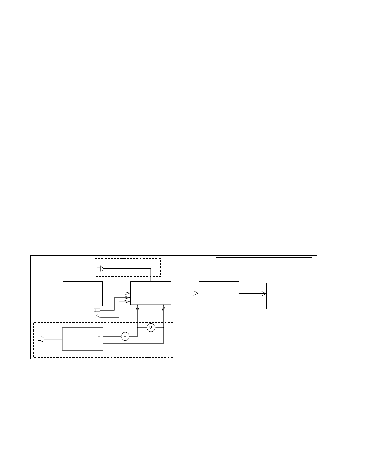
Block Diagram:
AC ONLY
CAUTION!: Power must only be applied to the
attenuator input! Do not reverse input and output
terminals of the Bird 8329.
TWO-T
A
G
ENERATOR
WITCH
PTT S
ELEGRAPH KEY
T
P
S
ONE
UDIO
OWER
UPPLY
DUT
RANSMITTER
T
100 W
T
YPICAL
ATTS
RF W
B
ATTMETER
4381
IRD
100 W
T
YPICAL
ATTS
DC ONLY
ARRL Laboratory Expanded Test-Result Report Model: Kenwood TS-2000 Serial: 20800064
Copyright 2001, American Radio Relay League, Inc. All Rights Reserved.
Page 4
RF Power
Attenuator &
Dummy Load
Bird 8329

Transmitter Output Power Test Results
Frequency
Band
1.8 MHz CW 5 3.0 W “100” 88.2 W
3.5 MHz CW 5 3.3 “100” 98.2
3.5 MHz AM 5 3.3 “25” 22.4
7.0 MHz CW 5 3.7 “100” 102.7
10.1 MHz CW 5 3.9 “100” 103.7
14 MHz CW 5 3.7 “100” 104.1
14 MHz USB 5 3.9 “100” 103.8
18 MHz CW 5 4.0 “100” 103.7
21 MHz CW 5 3.7 “100” 104.0
24 MHz CW 5 4.0 “100” 103.7
28 MHz CW 5 3.8 “100” 103.6
28 MHz FM 5 – “100” 103.4
50 MHz CW 5 3.8 “100” 105.5
144 MHz CW 5 4.0 “100” 97.5
144 MHz FM 5 – “100” 95.9
144 MHz AM 5 – “25” 21.8
432 MHz CW 5 6.8 “50” 50.7
432 MHz FM 5 – “50” 20.2
Mode Unit
Minimum
Power (W)
Measured
Minimum
Power (W)
Unit
Maximum
Power (W)
Measured
Maximum
Power (W)
Notes
Current Consumption Test
(DC-powered units only)
Test Description: Current consumption can be a important to the success of mobile and portable operation. While it is most
important for QRP rigs, the ARRL Lab tests the current consumption of all equipment that can be operated from a battery or
12-14 Vdc source. The equipment is tested in transmit at maximum output power. On receive, it is tested at maximum
volume, with no input signal, using the receiver's broadband noise. Any display lights are turned on to maximum brightness, if
applicable. This test is not performed on equipment that can be powered only from the ac mains.
Current Consumption:
Voltage Transmit
Current
13.8 V 18.4 A 104.0 W 2.1 A ON
Output Power Receive Current Lights? Notes
Transmit Frequency Range Test
Test Description: Many transmitters can transmit outside the amateur bands, either intentionally, to accommodate MARS
operation, for example, or unintentionally as the result of the design and internal software. The ARRL Lab tests the transmit
frequency range inside the screen room. The purpose of the Transmit F requ en cy Range Test is t o determine the rang e of
frequencies, including those outside amateur bands, for w h ich th e transmitter may be used. The key test conditions are to test it at
rated power, using nominal supply voltages. Frequencies are as indicated on the transmitter frequency indicator or display.
Most modern synthesized transmitters are capable of operation outside the ham bands. However, spectral purity is not always
legal outside the hams bands, so caution must be used. In addition, most other radio services require that transmitting
equipment be type accepted for that service. Amateur equipment is not legal for use on other than amateur and MARS
frequencies.
ARRL Laboratory Expanded Test-Result Report Model: Kenwood TS-2000 Serial: 20800064
Copyright 2001, American Radio Relay League, Inc. All Rights Reserved.
Page 5

Transmit Frequency Range Test Results
Frequency Low-Frequency Limit High-Frequency Limit Notes
160 M 1.800 00 MHz 1.999 99 MHz
80 M 3.500 00 MHz 3.999 99 MHz
40 M 7.000 00 MHz 7.299 99 MHz
30 M 10.100 00 MHz 10.149 99 MHz
20 M 14.000 00 MHz 14.349 99 MHz
17 M 18.068 00 MHz 18.167 99 MHz
15 M 21.000 00 MHz 21.449 99 MHz
12 M 24.890 00 MHz 25.989 99 MHz
10 M 28.000 00 MHz 29.699 99 MHz
6 M 50.000 00 MHz 53.999 99 MHz
2 M 144.000 00 MHz 147.999 99 MHz
70 CM 430.000 00 MHz 449.999 99 MHz
CW Transmit Frequency Accuracy Test
Test Description: Most modern amateur equipment is surprisingly accurate in frequency. It is not uncommon to find
equipment operating within a few Hz of the frequency indicated on the frequency display. However, some units, notably
"analog" units, not using a phase-lock loop in the VFO design, can be off by a considerable amount. This test measures the
output frequency. Unit is operated into a 50-ohm resistive load at nominal temperature and supply voltage. Frequency is also
measured at minimum output power, low supply voltage (12 volt units only) and over the operating temperature range (mobile
and portable units only). Non-portable equipment is not tested in the temperature chamber.
Test Results:
Unit Frequency Supply
Voltage
14.000 00 MHz 13.8 V 25 C 14.000 005 MHz
50.000 00 MHz 13.8 V 25 C 50.000 024 MHz
144.000 00 MHz 13.8 V 25 C 144.000 077 MHz
430.000 00 MHz 13.8 V 25 C 430.000 241 MHz
Temperature Measured Frequency
Full Output Power
Notes
Spectral Purity Test
Test Description: All transmitters emit some signals outside their assigned frequency or frequency range. These signals are
known as spurious emissions or "spurs." Part 97 of the FCC rules and regulations specify the amount of spurious emissions that
can be emitted by a transmitter operating in the Amateur Radio Service. The ARRL Laboratory uses a spectrum analyzer to
measure the spurious emission on each band on which a transmitter can operate. The transmitter is tested across the band and
the worst-case spectral purity on each band is captured from the spectrum analyzer and stored on disk. Spectral purity is
reported in dBc, meaning dB relative to the transmitted carrier.
The graphs and tables indicate the relative level of any spurious emissions from the transmitter. The lower that level, expressed
in dB relative to the output carrier, the better the transmitter is. So a transmitter whose spurious emissions are -60 dBc is
spectrally cleaner than is one whose spurious emissions are -30 dBc. FCC Part 97 regulations governing spectral purity are
contained in 97.307 of the FCC rules. Information about all amateur rules and regulations is found in the ARRL FCC Rule
Book. Additional information about the decibel is found in the ARRL Handbook.
ARRL Laboratory Expanded Test-Result Report Model: Kenwood TS-2000 Serial: 20800064
Copyright 2001, American Radio Relay League, Inc. All Rights Reserved.
Page 6

Key Test Conditions:
Unit is operated at nominal supply voltage and temperature.
Output power is adjusted to full power on each amateur band.
A second measurement is taken at minimum power to ensure that the spectral output is still legal at low power.
The level to the spectrum analyzer is –10 dBm maximum.
The resolution bandwidth of the spectrum analyzer is 10 kHz on HF, 100 kHz on VHF, 1 MHz on UHF.
Block Diagram:
CAUTION!: Power must only be app lied to
the attenuator input! Do not reverse input
and output terminals of the Bird 8329.
TWO-T
ONE
A
G
ENERATOR
ELEGRAPH KEY
T
OWER SOURCE
P
UDIO
T
A
Spectral Purity Test Results:
Frequency Spurs (dBc) Notes
1.8 MHz –66
3.5 MHz –60
7 MHz –55
10.1 MHz –56
14 MHz –59
18 MHz –60
21 MHz –60
24 MHz –63
28 MHz –60
50 MHz –63
144 MHz –69
430 MHz –69
DUT
RANSMITTER
TEP
10 dB S
TTENUATOR
HP 355D
100 W
T
YPICAL
ATTS
RF W
ATTMETER
B
4381
IRD
1 dB S
TTENUATOR
A
HP 3555C
TEP
100 W
T
YPICAL
DO NOT
EXCEED
0 dBm
ATTS
RF Power
Attenuator &
Dummy Load
Bird 8329
PECTRUM
S
NALYZER
A
HP 8563E
ARRL Laboratory Expanded Test-Result Report Model: Kenwood TS-2000 Serial: 20800064
Copyright 2001, American Radio Relay League, Inc. All Rights Reserved.
Page 7
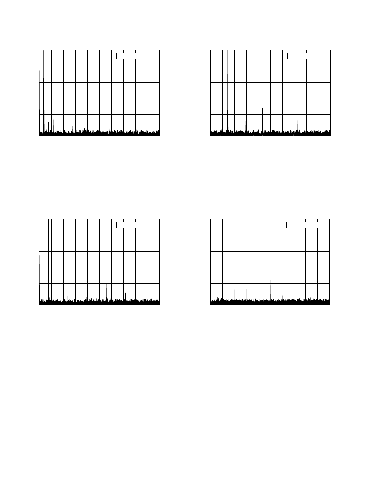
Spectral-Purity Graphs:
0
–10
Reference Level: 0 dBc
0
Reference Level: 0 dBc
–10
–20
–30
–40
–50
–60
–70
–80
0 5 10 15 20 25 30 35 40 45 50
Kenwood TS-2000 s/n 20800064
1.8 MHz Band, Spectral Purity, 100 W
F:\SHARED\PROD_REV\TESTS\TS2000\TS200SLO.TXT
Frequency (MHz)
0
–10
Reference Level: 0 dBc
–20
–30
–20
–30
–40
–50
–60
–70
–80
0 5 10 15 20 25 30 35 40 45 50
Kenwood TS-2000 s/n 20800064
7.0 MHz Band, Spectral Purity, 100 W
F:\SHARED\PROD_REV\TESTS\TS2000\TS200S40.TXT
0
Frequency (MHz)
Reference Level: 0 dBc
–10
–20
–30
–40
–50
–60
–70
–80
0 5 10 15 20 25 30 35 40 45 50
Kenwood TS-2000 s/n 20800064
3.5 MHz Band, Spectral Purity, 100 W
F:\SHARED\PROD_REV\TESTS\TS2000\TS200S80.TXT
Frequency (MHz)
–40
–50
–60
–70
–80
0 10 20 30 40 50 60 70 80 90 100
Kenwood TS-2000 s/n 20800064
10.1 MHz Band, Spectral Purity, 100 W
F:\SHARED\PROD_REV\TESTS\TS2000\TS200S30.TXT
Frequency (MHz)
ARRL Laboratory Expanded Test-Result Report Model: Kenwood TS-2000 Serial: 20800064
Copyright 2001, American Radio Relay League, Inc. All Rights Reserved.
Page 8

–10
0
Reference Level: 0 dBc
0
Reference Level: 0 dBc
–10
–20
–30
–40
–50
–60
–70
–80
0 10 20 30 40 50 60 70 80 90 100
Kenwood TS-2000 s/n 20800064
14.0 MHz Band, Spectral Purity, 100 W
F:\SHARED\PROD_REV\TESTS\TS2000\TS200S20.TXT
Frequency (MHz)
0
–10
Reference Level: 0 dBc
–20
–30
–20
–30
–40
–50
–60
–70
–80
0 10 20 30 40 50 60 70 80 90 100
Kenwood TS-2000 s/n 20800064
21.0 MHz Band, Spectral Purity, 100 W
F:\SHARED\PROD_REV\TESTS\TS2000\TS200S15.TXT
0
Frequency (MHz)
Reference Level: 0 dBc
–10
–20
–30
–40
–50
–60
–70
–80
0 10 20 30 40 50 60 70 80 90 100
Kenwood TS-2000 s/n 20800064
18.1 MHz Band, Spectral Purity, 100 W
F:\SHARED\PROD_REV\TESTS\TS2000\TS200S17.TXT
Frequency (MHz)
–40
–50
–60
–70
–80
0 20 40 60 80 100 120 140 160 180 200
Kenwood TS-2000 s/n 20800064
24.9 MHz Band, Spectral Purity, 100 W
F:\SHARED\PROD_REV\TESTS\TS2000\TS200S12.TXT
Frequency (MHz)
ARRL Laboratory Expanded Test-Result Report Model: Kenwood TS-2000 Serial: 20800064
Copyright 2001, American Radio Relay League, Inc. All Rights Reserved.
Page 9

–10
0
Reference Level: 0 dBc
0
Reference Level: 0 dBc
–10
–20
–30
–40
–50
–60
–70
–80
0 20 40 60 80 100 120 140 160 180 200
Kenwood TS-2000 s/n 20800064
28.0 MHz Band, Spectral Purity, 100 W
F:\SHARED\PROD_REV\TESTS\TS2000\TS200S10.TXT
0
–10
–20
–30
Frequency (MHz)
Reference Level: 0 dBc
–20
–30
–40
–50
–60
–70
–80
0 100 200 300 400 500 600 700 800 900 1000
Kenwood TS-2000 s/n 20800064
144.0 MHz Band, Spectral Purity, 100 W
F:\SHARED\PROD_REV\TESTS\TS2000\TS200S2M.TXT
0
–10
–20
–30
Frequency (MHz)
Reference Level: 0 dBc
–40
–50
–60
–70
–80
0 50 100 150 200 250 300 350 400 450 500
Kenwood TS-2000 s/n 20800064
50.0 MHz Band, Spectral Purity, 100 W
F:\SHARED\PROD_REV\TESTS\TS2000\TS200S6M.TXT
Frequency (MHz)
–40
–50
–60
–70
–80
0 200 400 600 800 1000 1200 1400 1600 1800 2000
Kenwood TS-2000 s/n 20800064
420.0 MHz Band, Spectral Purity, 100 W
F:\SHARED\PROD_REV\TESTS\TS2000\TS200S70.TXT
Frequency (MHz)
ARRL Laboratory Expanded Test-Result Report Model: Kenwood TS-2000 Serial: 20800064
Copyright 2001, American Radio Relay League, Inc. All Rights Reserved.
Page 10

Transmit Two-Tone IMD Test
Test Description: Investigating the sidebands from a modulated transmitter requires a narrow-band spectrum analysis. In this
test, a two-tone test signal is used to modulate the transmitter. The display shows the two test tones plus some of the IMD
products produced by the SSB transmitter. In the ARRL Lab, a two-tone test signal with frequencies of 700 and 1900 Hz is
used to modulate the transmitter. These frequencies were selected to be within the audio passband of the typical transmitter,
resulting in a meaningful display of transmitter IMD. The intermodulation products appear on the spectral plot above and below
the two tones. The lower the intermodulation products, the better the transmitter. In general, it is the products that are farthest
removed from the two tones (typically > 3 kHz away) that cause the most problems. These can cause splatter up and down the
band from strong signals.
Key Test Conditions:
Transmitter operated at rated output power. Audio tone and drive level adjusted for best performance. Audio tones 700 and
1900 Hz. Both audio tones adjusted for equal RF output. Level to spectrum analyzer, –10 dBm nominal. Resolution
bandwidth, 10 Hz
Block Diagram:
CAUTION!: Power must only be app lied to
the attenuator input! Do not reverse input
and output terminals of the Bird 8329.
TWO-T
A
G
ENERATOR
ELEGRAPH KEY
T
OWER SOURCE
P
ONE
UDIO
DUT
RANSMITTER
T
10 dB S
TTENUATOR
A
HP 355D
Transmit Two-Tone IMD Te st Result:
Frequency Worst-case
3rd-order
dB PEP
Worst-case
5th-order
dB PEP
1.85 MHz –27 –42
3.9 MHz –32 –46
7.25 MHz –35 –60
10.12 MHz –33 –53
14.25 MHz –33 –52
18.12 MHz –30 –53
21.25 MHz –32 –49
24.95 MHz –30 –53
28.35 MHz –31 –53
50.2 MHz –20 –35
144.2 MHz –22 –35
432.2 MHz –29 –40
TEP
Notes
100 W
T
YPICAL
ATTS
RF W
ATTMETER
B
4381
IRD
1 dB S
TTENUATOR
A
HP 3555C
TEP
100 W
T
YPICAL
DO NOT
EXCEED
0 dBm
ATTS
RF Power
Attenuator &
Dummy Load
Bird 8329
PECTRUM
S
NALYZER
A
HP 8563E
ARRL Laboratory Expanded Test-Result Report Model: Kenwood TS-2000 Serial: 20800064
Copyright 2001, American Radio Relay League, Inc. All Rights Reserved.
Page 11
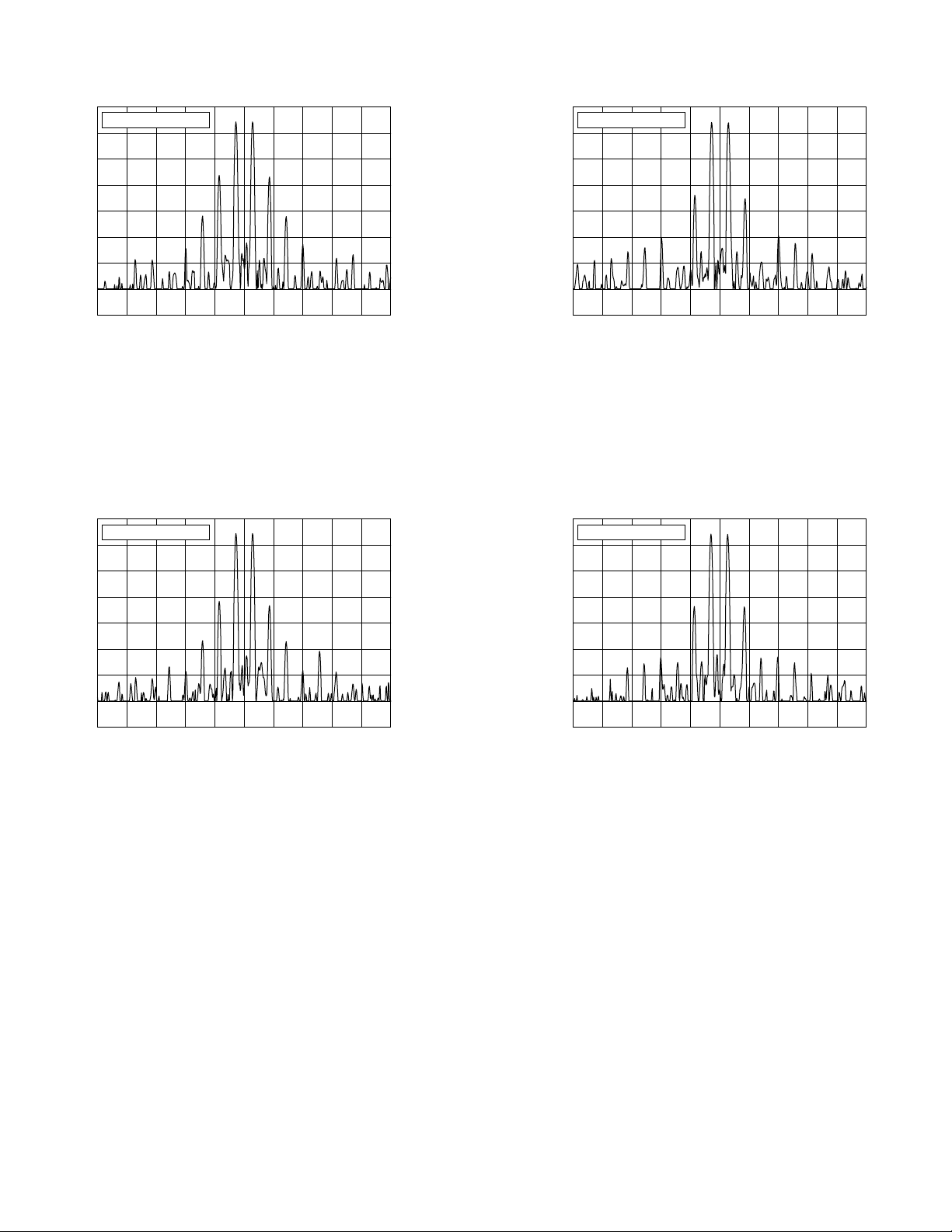
Transmit IMD Graphs
0
Reference Level: 0 dB PEP
–10
–20
–30
–40
–50
–60
–70
–80
–10 –8 –6 –4 –2 0 2 4 6 8 10
Kenwood TS-2000 s/n 20800064
1.850 MHz, Transmit IMD, 100 W
F:\SHARED\PROD_REV\TESTS\TS2000\TS200ILO.TXT
Frequency Offset (kHz)
0
Reference Level: 0 dB PEP
–10
–20
–30
–40
–50
–60
–70
–80
–10 –8 –6 –4 –2 0 2 4 6 8 10
Kenwood TS-2000 s/n 20800064
7.250 MHz, Transmit IMD, 100 W
F:\SHARED\PROD_REV\TESTS\TS2000\TS200I40.TXT
Frequency Offset (kHz)
0
Reference Level: 0 dB PEP
–10
–20
–30
–40
–50
–60
–70
–80
–10 –8 –6 –4 –2 0 2 4 6 8 10
Kenwood TS-2000 s/n 20800064
3.900 MHz, Transmit IMD, 100 W
F:\SHARED\PROD_REV\TESTS\TS2000\TS200I80.TXT
Frequency Offset (kHz)
0
Reference Level: 0 dB PEP
–10
–20
–30
–40
–50
–60
–70
–80
–10 –8 –6 –4 –2 0 2 4 6 8 10
Kenwood TS-2000 s/n 2080064
10.120 MHz, Transmit IMD, 100 W
F:\SHARED\PROD_REV\TESTS\TS2000\TS200I30.TXT
Frequency Offset (kHz)
ARRL Laboratory Expanded Test-Result Report Model: Kenwood TS-2000 Serial: 20800064
Copyright 2001, American Radio Relay League, Inc. All Rights Reserved.
Page 12
 Loading...