

Page 1
» «* m »#^**» ■•»«# « **■#-*• ni ~:
* »»«(:* 4>mMm^M * »■•'» sr^asc»
■i » » ■: ■
if'/
»♦ttH
i. ^ &&-w%-
»***»«. St
,4.- '
y -
wiiS
i;r ^.1
^ ^ y.
-f /./^ S:
^ ^
" r^ //
..........
t-^ ♦ . .#/ ^1
,\/'Z/'/ ''"',i *''■
. nit> ^ ^ ‘
.......
* '< ^\Sf .y <"i ..
^"'' '.
Model TS-130SE
\A
INSTRUCTION MANUAL
i.#£%-iS3
Page 2

INTRODUCTION
You are the owner of our latest product the new TS-130SE transceiver. Please read this in
struction manual carefully before placing your transceiver in service. The unit has been
carefully engineered and manufactured to rigid quality standards, and should give you
satisfactory and dependable operation for many years.
AFTER UNPACKING:
• Shipping container:
Save the boxes and packing in the event your unit needs to be transported for remote
operation, maintenance, or service.
• The following explicit definitions apply in this manual:
Note: If disregarded inconvenience only, no risk of equipment damage or personal
injury.
Caution: Equipment damage may occur, but not personal injury.
CONTENTS
SPECIFICATIONS...................................................................................................................................................... 3
SECTION 1. FEATURES.............................................................................................................................................. 4
SECTION 2. PREPARATION FOR USE
2.1 INTERCONNECTION
2.2 ACCESSORIES...................................................................................................................................... 6
2.3 INSTALLATION...................................................................................................................................... 6
SECTION 3. CONTROLS
3.1 FRONT PANEL...................................................................................................................................... 6
3.2 REAR TOP PANEL................................................................................................................................ 8
SECTION 4. OPERATION
4.1 RECEPTION.......................................................................................................................................... 9
4.2 TRANSMISSION.................................................................................................................................. 10
4.3 VOX OPERATION............................................................................................................................... 12
4.4 SEMI-BREAK-IN OPERATION............................................................................................................ 12
4.5 OPERATION WITH A LINEAR AMPLIFIER ....................................................................................... 12
4.6 FIXED CHANNEL OPERATION ......................................................................................................... 12
4.7 CW OPERATION................................................................................................................................. 13
4.8 MOBILE OPERATION.......................................................................................................................... 14
4.9 FIXED STATION OPERATION............................................................................................................ 16
4.10 DIGITAL DISPLAY CALIBRATION...................................................................................................... 17
4.11 ANALOG DIAL CALIBRATION............................................................................................................ 17
SECTION 5. ADDITIONAL INFORMATION...................................................................................................... 17
SECTION 6. OPTIONAL ACCESSORIES.................................................................................................................. 20
INTERNAL VIEWS...................................................................................................................................................... 22
BLOCK DIAGRAM...................................................................................................................................................... 23
SCHEMATIC DIAGRAM........................................................................................................................................ 24~30
..............
............................................................................................................. 5
Page 3

•mil • •Mill« iMin ••Mill •nuil* -«11111 • ■ •llll«•l|lll*•lllll»•llllll•«lllli•lllll*••llll»•*MII>•«IIM»‘l
-lltlll•|||||l•llllll•lMll•>llllм•*llll»•ммl»•«|lMi*«NHl•«llHl•«l••l••l|lll»••мf•••tмн••mlll•*ml••«lм••мN•t•••mк
^M«••llll•••MII•■•tltll••lllll••IIM••
[GENERALI
Frequency Ranga:
Mode:
Frequency Stability:
Power Requirement:
Dimensions:
Weight:
[TRANSMISSTER]
Final Power Input:
Audio Input Impedance:
RF Output Impedance:
Carrier Suppression:
Sideband Suppression:
Spurious Radiation:
Harmonic Radiation:
TS-130SE SPECIFICATIONS
•inn• 111111 «lini•mill-Hiiii •Hill•null-
■«llln•«|lll»•«lllll•«llll>•
«llм»•«llll»•llllll•ммll•мmlн
80 meter band 3.5 ~ 4.0 MHz
40 meter band 7.0 ~
♦30 meter band
10.1 ~ 10.15 MHzdO.i
20 meter band 14.0 ~
*1 7 meter band
1 5 meter band
♦12meter band
10 meter band
18.068
21.0 ~
24.89 -
28.0 ~
7.3 MHz
14.35 MHz
~ 18.168 MHz
21.45 MHz
- 24.99 MHz
29.7 MHz
SSB/CW
Within ± 1 kHz during the first hour after 1 minute of warmup
Within 100 Hz during any 30-minute period after warmup
12 ~ 16V DC (13.8V Nominal)
RX: 0.7A 13.8V DC
TX: 19A 13.8V DC
241 (9.6) W X 94 (3.8) H x 293 (1 1.7) D mm (inch)
5.6 kg (12.4 lbs)
80—15 meter band
200W PEP for SSB operation
160W DC for CW operation
10 meter band
160W PEP for SSB operation
140W DC for CW operation
50012 ~ 50 kl2
5012
Better than 40 dB
Better than 50 dB
Better than 40 dB
Better than 40 dB
'l•lll••lHll*•«llll••«llll••l||||l•«|||||.lMH••lNl•»•«||•l».«l•мa
[RECEIVER]
Receiver Sensitivity:
Image Ratio:
IF Rejection:
0.25AiVat 10 dB S-l-N/N
Better than 50 dB
Better than 70 dB
Receiver Selectivity:
SSB/CW WIDE
SSB NARROW
CW NARROW
2.4 kHz (-6 dB), 4.2 kHz(-60dB)
1.8 kHz (- 6 dB), 3.3 kHz (- 60 dB) with optional YK-88SN filter
500 Hz (- 6 dB), 1.5 kHz (- 60 dB) with optional YK-88C filter
270 Hz (- 6 dB), 1.1 kHz (- 60 dB) with optional YK-88CN filter
Audio Output Impedance:
Audio Output:
4~1612
1.5 W
NOTE: Circuit and ratings may change without notice due to developments in technology.
* Will transmit on the new 30, 17, and 12 meter bands. Diodes installed for preventing accidental transmission be
fore government amateur authorization.
Page 4

SECTION 1. FEATURES
1. SINGLE-CONVERSION SYSTEM USING PLL
CIRCUITRY
The single-conversion system, with a unique Phase Locked
Loop circuit, FET balanced mixers and MOS FET's, assures
excellent spurious and intermod characteristics.
2. BUILT-IN DIGITAL DISPLAY
The digital display affords easy reading of operating frequen
cy to an accuracy of 100 Hz on any band and any mode.
3. BUILT-IN IF SHIFT CIRCUIT (Passband Tuning)
An IF SHIFT system is built into the transceiver to allow shif
ting the IF passband, thereby eliminating adjacent channel
interference.
4. 3.5 ~ 29.7 MHz BAND
The transceiver is designed to operate on LSB/USB/CW in
the 3.5 ~ 29.7 MHz bands. As supplied, the 10, 18, and
24.5 MHz bands are for reception only. The VFO covers ±
50 KHz above and below each band for near-MARS frequenies. (with the DFC-230, ± 100 kHz.)
5. IMPROVED TWO SIGNAL CHARACTERISTICS
High performance circuit elements in the front end and
optimum signal level distribution result in improved inter
modulation and blocking characteristics.
6. BUILT-IN RF ATTENUATOR
Built-in 20 dB attenuator protects the RF amplifier and
mixer from strong signals or a strong interfering adjacent
signal. This also prevents cross modulation and blocking.
11. ALL SOLID-STATE DESIGN
The all solid-state, compact unit features a wide-band final
stage, eliminating the need for peaking controls.
12. A FIXED CHANNELS
A fixed channel is available for common use on all bands by
installing a crystal in the socket on the AF-GAIN unit.
13. FULL RANGE OF AUXILIARY FUNCTIONS
It is equipped with VOX, balanced-gate noise blanker for
pulse noise rejection, and a 25 kHz marker.
14. SSB narrow filter YK-88SN
An optional SSB narrow filter YK-88SN can be installed.
(Reception only)
15. OPTIONAL CW FILTERS YK-88C AND YK-88CN
The TS-130SE permits use of the optional YK-88C or
YK-88CN CW filter (Reception only). CW semi-break-in
operation is provided using the built-in VOX and CW
side-tone circuits.
16. WIDE VARIETY OF OPTIONAL ACCESSORIES
The following optional accessories are available: Regulated
power supply (PS-30) for the TS-130SE, frequency con
troller (DFC-230), external VFO (VFO-120), external speaker
(SP-120), mobile mount (MB-100), fan unit (FA-4), CW
filter (YK-88C), CW narrow filter (YK-88CN), SSB narrow
filter (YK-88SN), and other optional units.
7. BUILT-IN SPEECH PROCESSOR
Built-in speech processor provides audio compression and
varies the ALC time constant simultaneously, resulting in
minimal degradation of sound quality.
8. AUTOMATIC SSB MODE SWITCHING
The SSB mode is selected automatically according to the
band selected. When the band selected is 10 MHz or
higher, USB is selected. When it is below 10 MHz, LSB is
selected. Mode selection can be reversed by setting the
mode switch to the REV position.
9. COMPACT, LIGHTWEIGHT DESIGN
The TS-130SE has many advanced features, yet it is com
pact and lightweight, suitable for mobile and field operations
as well as fixed-station operation.
10. EASY OPERATION
All controls and switches are carefully arranged for ease of
operation, ensuring convenience and versatility.
Page 5
SECTION 2. PREPARATION FOR USE
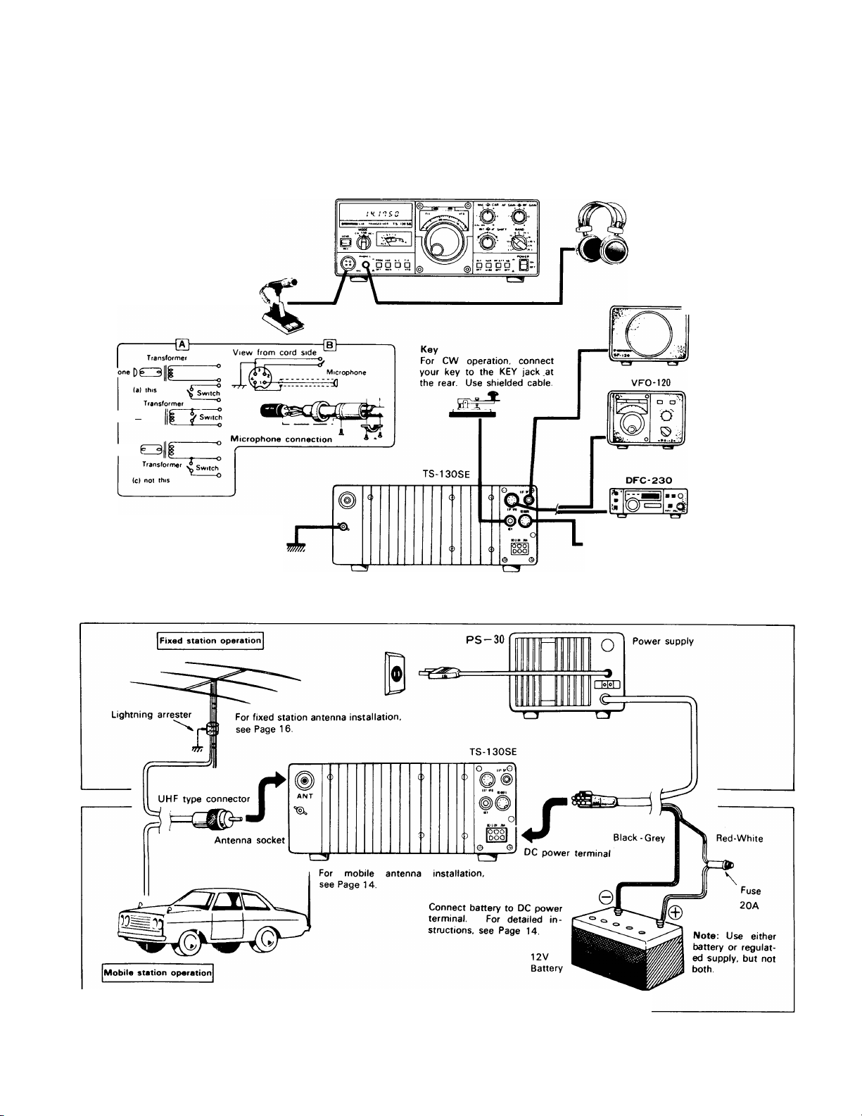
2.1 INTERCONNECTION
Connect the transceiver as illustrated in Fig. 2-1.
'4||||l«l||||»*4||||».4mil-<llll»-mil»>4|t||*>4|MI»-<|MI»-4|M|»-lMM»-MIII*-l|lll»>4tm»*4M||l>l||||l*4l|||».|||M>>«lll|l««lll|4<ll|||»-4tlll»-l|lir
Microphone
Either a low or high imped
ance microphone (50012 to
50ki2) can be used. The P.T.T.
switch should be isolated
from the mic circuit (shown in
"a") Use a microphone with
a separate switch and MIC
line so both P.T.T. and VOXare available.
Microph
Ircrophone [)(»
(b) noi this
Microphone 0
GND terminal
It is recommended that a ground
lead be connected to the GND
terminal at the rear of the set to
prevent the possibility of electric
shock. TVI and BCI. Use as short,
and heavy a lead as possible
TS-130SE
Fig. 2-1 [A] TS-130SE Interconnection
Headphones
Use headphones of 4 to 1612
impedance. The optional HS6,5.4 headphone is best suited
for use with the TS-130SE.
Stereo type headphones can
also be used.
External speaker
SP-120 speaker, an external
REMOTE connector
External accessories can be con
nected to the TS-130SE through
the REMOTE connector. The PTT
terminal can be used for remote
control of send/receive operation
Besides the built-in
=^speaker can also be
used Connect to the
rear EXT SP jack using
the supplied plug.
External VFO
For connection of ex
ternal VFO-120
Note: VFO-520 and
VFO-820 cannot be
used
Frequency Controller
DFC-230
The DFC-230 incorpo
rates a digital VFO
operating at 20 Hz
step, and 4 memory
channels permitting
remote frequency
control.
Fig. 2-1 [B] Antenna and Power Supply Connection for TS-130SE
Page 6
2.2 ACCESSORIES
The following accessories are furnished with the TS-
130SE.
DC power cord (E30-1638-05)
........................................
1
Fuse, 20A (F05-2034-05)................................................ 1
Instruction manual (B50-3954-00)
..................................
1
2.3 INSTALLATION
It is preferable to choose an operating location that is dry
and cool, and to avoid operating the transceiver in direct
SECTIONS. CONTROLS
sunlight.
Allow adequate ventilation, particularly during mobile opera
tion.
NOTE:
The TS-130SE is supplied to receive on the following
frequencies (transmission is disabled):
10 MHz band (10.0-10.25 MHz)
18 MHz band (18.0-18.5 MHz)
24.5 MHz band (24.5-25 0 MHz)
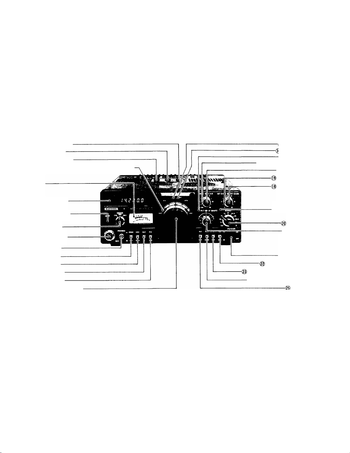
@ ANTI vox CONTROL
(g) DELAY CONTROL
@ VOX GAIN CONTROL
(Q) SUBDIAL
0 METER
DIGITAL DISPLAY
0 STANDBY SWITCH
0MODE SWITCH
0 MIC CONNECTOR
0 PHONES JACK
0 PROC SWITCH
0 VOX SWITCH
0 METER SWITCH
(g) FIX SWITCH
(||)MAIN TUNING CONTROL
Fig. 3-1
3.1 FRONT PANEL
0 METER
The meter has three functions, two being selected by the
METER switch. In receive the meter is automatically an Smeter showing receive signal strength on a scale of 1 ~ 9, 9
-I- 20, -h 40 and + 60 dB. In transmit, the meter shows
Ic or ALC level, depending on METER switch position.
0 DIGITAL DISPLAY
The digital display indicates true operating frequency to an
accuracy of 100 Hz.
0 MODE SWITCH
SSB
...............
Permits SSB operation. LSB is normally
selected for opration on the 3.5 and 7 MHz
bands, and USB for operation on and above
the 10 MHZ bands.
Switching between LSB and USB is done
automatically by the BAND switch.
g)FIX INDICATOR
§)VOX INDICATOR
(0)RIT INDICATOR
(0) CARRIER LEVEL CONTROL
(Tt) MIC CONTROL
RF GAIN CONTROL
AF GAIN CONTROL
(Q) IF SHIFT CONTROL
BAND SWITCH
@ RIT CONTROL
0 POWER SWITCH
NOISE BLANKER SWITCH
RF ATT(RF ATTENUATOR) SWITCH
0 NAR WIDE SWITCH
_ RIT SWITCH
Front Panel
REV
...............
During SSB operation, this position selects
the reverse side band; from USB to LSB or
vice versa.
CW
.................
Used for CW operation.
0 STANDBY SWITCH
This switch selects receive or transmit function.
In the REC position, the transceiver is normally in the receive
mode unless the microphone PTT switch is depressed. In
the SEND position, the TS-130SE is switched to the
transmit mode.
CAUTION: Do not transmit without an antenna or dummy
load. Equipment damage will occur. Such damage is not
covered by warranty.
0 MIC CONNECTOR
Connect your microphone (MC-30S, MC-35S, MC-50, MC60/N4, etc.), referring to Fig. 2-1. The TS-130SE accepts
both low and high impedance microphones.
6
Page 7

(D PHONES JACK
The headphone jack allows use of 4-to-l 6-ohm (or greater)
headphones. HS-6, HS-5, HS-4 optional headphones
provide optimum results. Stereo-type headphones can also
be sued. This will disable the internal and external speaker.
® PROC (processor) switch
During SSB transmission, the speech processor may be
used to increase "talk power".
® VOX (VOICE OPERATED TRANSMIT) SWITCH
This function is used for SSB VOX or CW semi-break-in operation. In the MAN (manual) position, the transceiver is
keyed by either the standby switch or the microphone PTT
switch. For VOX operation, the standy switch remains in
REC. (See page 11.)
(D METER SWITCH
During transmission, the meter switch determines meter
function. The switch selects between:
ALC
....................
The meter monitors the output of the final
stage power amplifier during transmis
sion. During SSB operation, adjust the
MIC control so that the meter pointer is
within the ALC zone. Similarly, adjust the
CAR control for CW operation.
1C....................... The meter monitors final stage collector
current. 12 ~ 19A is normal, 17A typical.
@ FIX (fixed channel) SWITCH
The TS-130SE has a built-in fixed channel oscillator
(crystals are user-provided, optional) which is activated by
the FIX switch for fixed channel or VFO operation.
(D) SUBDIAL
The subdial is calibrated from 0 to 500. It is driven from the
main tuning knob to indicate the transceiver's operating
frequency.
® MAIN TUNING CONTROL
This control is used to select the desired operating frequen
cy. The scale on the control knob is calibrated at 1 kHz in
tervals, allowing accurate tuning. For exact frequency, read
the Digital Display.
(0) RIT INDICATOR
This light emitting diode indicates the RIT circuit is ON.
(Q) IF SHIFT CONTROL
By using this control, the IF crystal filter center frequency
can be shifted ±1 kHz, allowing adjustment of tone quality,
or eliminating interference from adjacent frequencies.
For normal operation, this control should be set to the center
"0" position (detent).
@
RIT CONTROL
When the RIT circuit is ON, this will vary receive frequency
by about ±1.5 kHz. When the control is set to the "0"
center position, there is no frequency shift.
(3) CAR (CARRIER LEVEL) CONTROL
This control is used to adjust the carrier output level and is
effective only during CW operation. Adjust the control so
the ALC meter indication is within the ALC zone. For "QRP"
operation, reduce carrier insertion.
(0) MIC (MICROPHONE GAIN) CONTROL
This adjusts mic amplifier gain during SSB operation. Again,
adjust the control so the ALC meter indication is within the
ALC zone.
When this control is set to the CAL ON position, the built-in
calibrator is activated, permitting calibration of the receiver
dial scale at 25 kHz intervals.
(0) AF GAIN (AUDIO GAIN) CONTROL
This control adjusts the receiver audio amplifier gain.
Volume of the received signal increases as the control is
turned clockwise.
@ RF GAIN CONTROL
This adjusts the receiver section's RF amplifier gain. Turn
the control fully clockwise for maximum gain. Turn
counterclockwise to reduce the gain.
(g) BAND SWITCH
This switch selects all Amateur bands from 3.5 — 29.7
MHz. The 10, 18, and 24.5 MHz bands as supplied are
for reception only, and transmission on these frequencies
is not possible. Use the 10 MHz band to receive WWV at
10.0 MHz.
CAUTION: —------------------------------------------------------------------
Do not turn the bandswitch during transmit.
(2) POWER SWITCH
This switches the TS-130SE ON and OFF.
@
NB (NOISE BLANKER) SWITCH
This switch is used to reduce pulsating ignition noises of the
type usually emitted from motor vehicles. Power-line, QRM
and atmospheric "white" noise will not operate the noise
blanker.
@ RF ATT (ATTENUATOR) SWITCH
With this switch ON, a 20 dB attenuator is inserted in the
antenna circuit, protecting the RF amplifier and mixer from
overload on strong input signals.
®
NAR/WIDE switch
This switch selects receive IF bandwidths between narrow
and wide. The WIDE position provides the same IF
bandwidth for both CW and SSB. For the NARROW posi
tion, optional filters are available for both CW and SSB.
®
RIT SWITCH
This push switch turns the RIT (Receiver Incremental Tun
ing) circuit ON and OFF. With the switch depressed, the cir
cuit is activated and the RIT indicator is illuminated, allowing
the receive frequency to be shifted by about ±1.5 kHz in
dependent of the transmit frequency by using the RIT con
trol. The RIT circuit is turned OFF when the switch is out.
Page 8
® vox GAIN CONTROL
This control adjusts VOX circuit sensitivity for both SSB and
CW operation.
(g) DELAY CONTROL
This control is used to adjust the "Hold" time of the VOX cir
cuit. Clockwise adjustment gives longer hold-time.
(g) ANTI-VOX CONTROL
This control is used to adjust the VOX system so that it is not
tripped by sound from the speaker.
NOTE:----------------------------------------
The VOX control panel (and serial number plate) is covered
by thin plastic brotective film which may be beeled off and
-----------------------------------
discarded. It is provided to protect the panel during ma
nufacture, and is not intended as a permanent part of the
radio.
®
FIX INDICATOR
The FIX indicator illuminates when the internal fixed
frequency oscillator controls transceiver operation.
(8) VFO INDICATOR
The VFO indicator illuminates when the internal VFO
controls transceiver operation. The indicator is not lighted
during fixed channel or remote VFO operation.
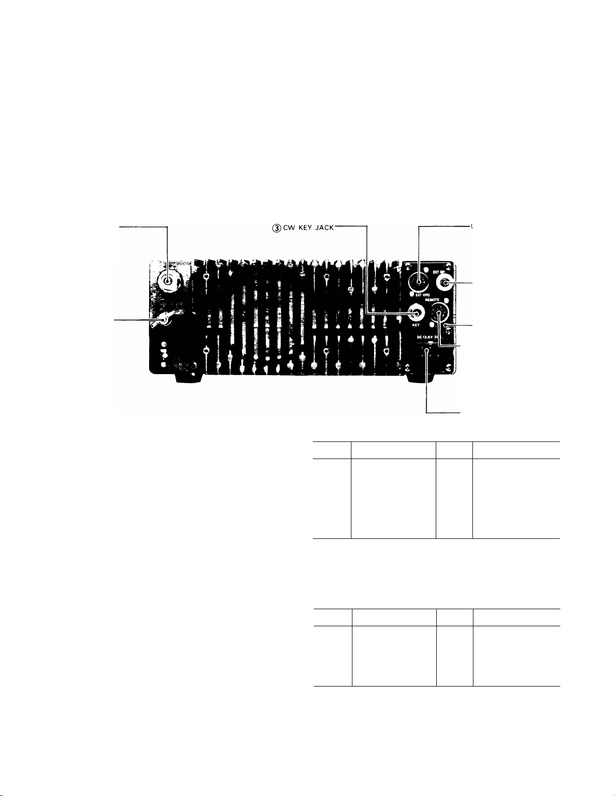
0ANT CONNECTOR
)GND TERMINAL
Fig 3-2 Rear. Top Panel
3.2 REAR PANEL
0 ANT (ANTENNA) CONNECTOR
This UHF connector should be attached to a suitable anten
na for transmitting and receiving. The antenna cable should
be 50-ohm coax, terminated with a PL-259 connector.
(D GND (GROUND) TERMINAL
The TS-130SE should be grounded through this terminal
to avoid the possibility of TVI and BCI. Use as short and
heavy a lead as possible.
(D CW KEY JACK
For CW operation, connect your key to this terminal using a
two conductor phone plug and shielded cable.
0 SPEAKER (EXTERNAL SPEAKER) JACK
An external speaker of 4 ~ 16 ohms impedance (such as
the SP-120) can be connected here. This will disable the in
ternal speaker.
(D REMOTE CONNECTOR
This connector is used to interconnect a linear amplifier or
other accessory item.
I EXT VFO CONNECTOR
-(4) SPEAKER JACK
REFERENCE FREQUENCY
ADJUSTMENT ACCESS
(D REMOTE CONNECTOR
0DC POWER CONNECTOR
PIN
1
2
3
4
FUNCTION PIN
Record output
Relay common
terminal
(NOT grounded)
PTT line
Normally opened
(relay contact)
5
6
7
FUNCTION
Normally closed
(relay contact)
ALC input
AlC threshold level
approx. — 6V
No connection
® EXT VFO (EXTERNAL VFO) CONNECTOR
This is for connection of an external VFO-120, or remote
Frequency Controller DFC-230. (Note: the VFO-520 and
VFO-820 cannot be used, since their operating frequency is
incorrect.)
PIN
1
2
3 -F9V 7 Ground
4
FUNCTION
VFO signal
Relay control
(+ on transmit)
CW freq. shift control
PIN
5 VFO control
6
Display control
8
+ 12V
FUNCTION
0 DC POWER CONNECTOR
This is used to connect the DC power supply.
® REFERENCE FREQUENCY ADJUSTMENT (SIDE)
For PLL reference oscillator adjustment. Use WWV signal
for calibration.
Page 9
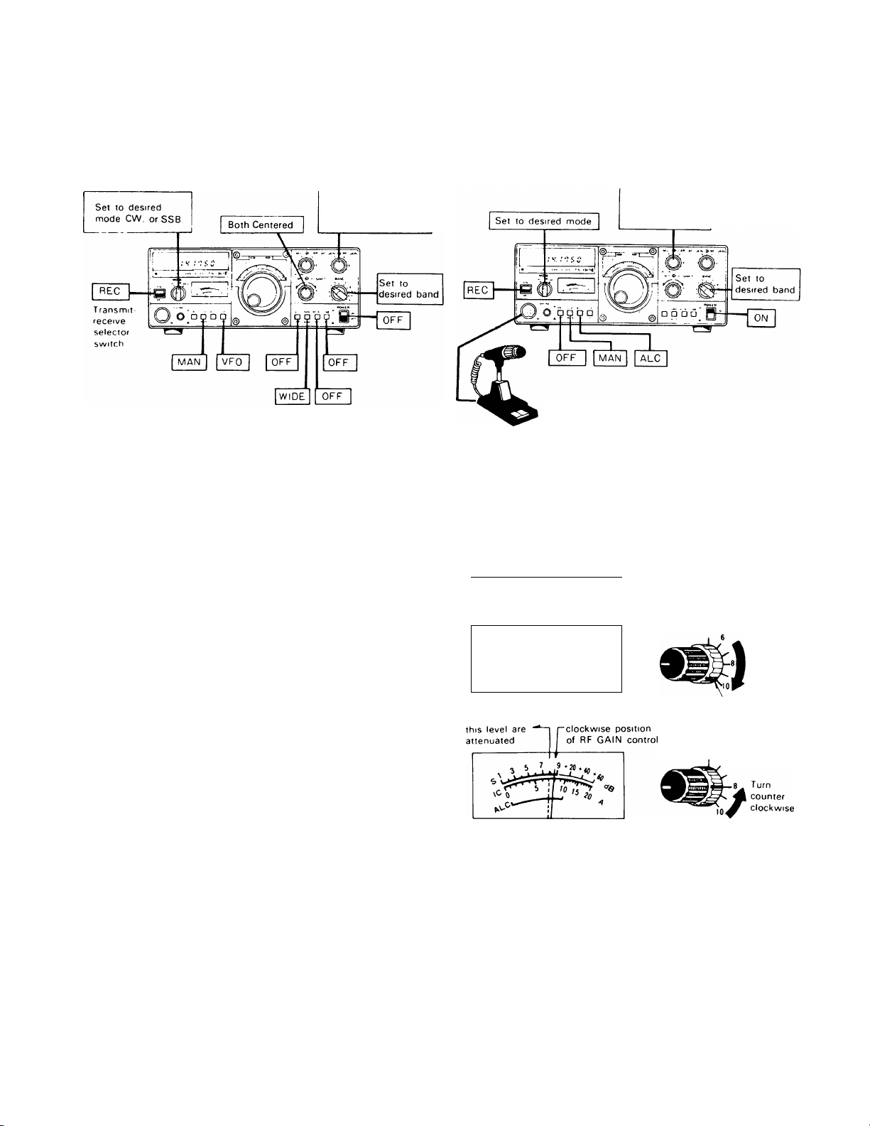
SECTION 4. OPERATION
Settings for reception Settings for transmission
RF Turn fully
clockwise
AF Turn fully
counterclockwise
Fig. 4-1 Control and Switch Settings
4.1 RECEPTION
First connect the antenna, microphone and key. Then, set
the controls and switches referring to Fig. 4-1.
Ascertain that the TS-130SE is ready for operation, then
turn the POWER switch ON. The meter, dial scale and
digital display will illuminate, indicating the transceiver is in
operation. The transceiver is fully solid-state, allowing
reception as soon as the POWER switch is turned ON.
Advance the AF GAIN control clockwise until some receiver
noise is heard from the speaker. Turn the main tuning con
trol so the desired signal can be heard clearly.
4.1.1. WWV RECEPTION
To receive WWV at 10 MHz, set the BAND switch to "10"
and turn the main tuning control until the subdial reads"0".
4.1.2 RF ATT switch
The input to the receive RF amplifier is attenuated ap
proximately 20 dB, providing distortion-free reception. This
feature may be used in cases of receiver overload, caused
either by a strong local signal, or during weak signal recep
tion when a strong adjacent signal may blank the receiver.
4.1.2. NB SWITCH
The TS-130SE has a sophisticated noise blanker designed
to reduce ignition-type pulse noise. The noise blanker is par
ticularly important for mobile operation. When necessary,
activate the noise-blanker by depressing the NB switch ON.
4.1.3. RF GAIN CONTROL (Fig. 4-2)
For normal operation, this control should be turned fully
clockwise for maximum sensitivity. Receive sensitivity is
reduced by turning the control counterclockwise.
Turn CAR and
MIC fully counter
clockwise
Microphone
Adjust the RF GAIN so the S-meter does not show ex
cessive deflection. This minimizes noise during reception
and allows the S-meter to indicates signal peak (or a little
below that point). Noise is markedly reduced when signal is
absent.
S-meter peak
\C> 0 ^
Signals below
-----------
point
S-meter reading
at partial counter-
AF GAIN —
4
Full
Clockwise
position
AF GAIN RF GAIN
6
Fig. 4-2 RF GAIN Control Operation
4.1.4. RIT CONTROL
By using the RIT (Receiver Incremental Tuning) control, the
receive frequency can be shifted by about ±1.5 kHz without
changing the transmit frequency.
If the frequency of the station you are working changes, your
receive frequency can be reset by turning the RIT switch ON
and adjusting the RIT control. Adjusting the control
clockwise increases the frequency. The RIT shift can be
checked by the digital display. When first calling another
station, the RIT should be OFF, otherwise your transmit and
receive frequency will not coincide.
Page 10
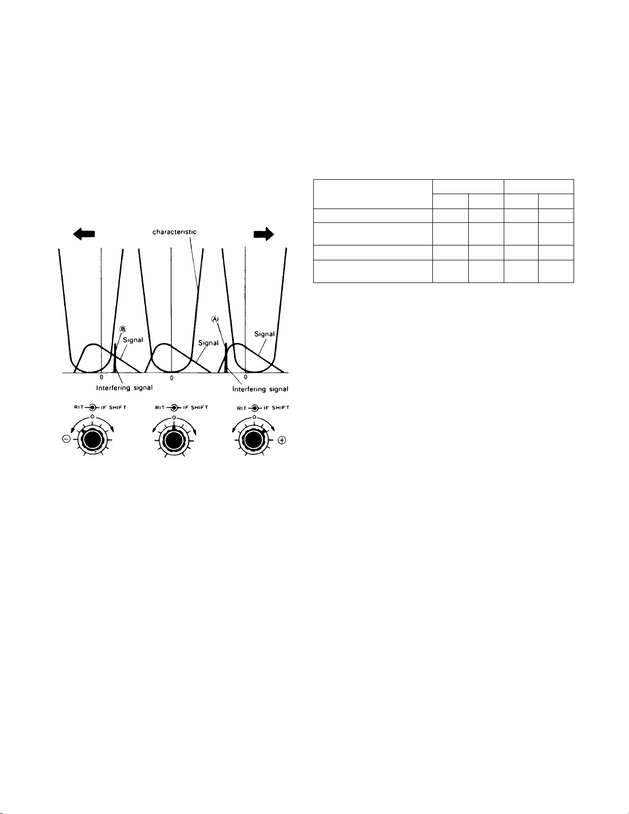
4.1.5. IF SHIFT CONTROL
The IF SHIFT control is used to shift the passband of the IF
filter without changing receive frequency. By turning this
control in either direction, the IF passband is shifted as
shown in Fig. 4-3.
The IF SHIFT is effective in eliminating interference when
the receive signal is superimposed on nearby signals during
operation in both SSB or CW mode.
Turned in 0 direction
IF filter passband
Turned in © direction
bandwidth is 2.4 kHz in the wide position, and 270 or
500Hz for CW (with optional filters YK-88CN and YK-88C
respectively) and 1.8 kHz for SSB (with optional filter
YK-88SN), both in the NAR position. In transmit,
bandwidth is automatically WIDE.
PASSBAND WIDTH (-6dB) kHz
WIDE
2.4
2.4
2.4
2.4
SSB
NARROW
•
«
1.8
1.8
MODE
FILTER
No optional filter 2.4
YK-88C or CN 2.4
YK-88SN 2.4
YK-88C or CN
YK-88SN
WIDE NARROW
2.4
CW
*
500
or 270
1.8
500
or 270
* Can not be received.
4,2 TRANSMISSION (Fig. 4-4)
e ©
Turn in © direction
to eliminate inter
ference from signal (§)
© 0
Turn in © direction
to eliminate inter
ference from signal @
Fig. 4-3 IF SHIFT CONTROL
(1) USB Mode (10 MHz and above)
Adjust the IF SHIFT control in the © direction and lower
frequencies are cut. Adjust the control in the © direction
and high frequencies are cut.
(2) LSB Mode (3.5, 7 MHz)
Adjust the control in the © direction and higher frequencies
are cut. Adjust the control in the © direction and low fre
quencies are cut.
(3) CW Mode
By using the IF SHIFT in conjunction with the RIT, tone
quality can be adjusted.
4.1.7 NAR-WIDE switch operation
For short to medium distance communication, the WIDE
position may be used for both SSB and CW operation. For
DX (long distance) communication, the NAR position will be
an advantage in reducing interference.
This feature, in combination with the IF SHIFT control, will
provide outstanding interference rejection. The receive IF
CAUTION:
-------------------------------------------
Before transmitting, be sure to connect an antenna or dum
my load with a VSWR of less than 1.5:1. Never attempt to
transmit with the antenna terminal left open.
When testing the transmitter, connect a 50-ohm dummy
load, rated at more than 100W. Refer to Fig. 4-1 for initial
control settings.
When the TS-130SE is ready for transmission, use the
following procedure;
• SSB Operation
1 Set the MODE switch to SSB.
2 Meter switch to ALC.
3 Standby switch to SEND.
4 Speak into the microphone and adjust the MIC GAIN for
meter deflection within the ALC zone at signal peaks.
• PROC (processor) operation
In DX (long distance) operation, it may be desirable to in
creased talk-power by using the speech processor.
The speech processor in the TS-130 Series combines an
audio compression amplifier with changes in ALC time cons
tant to provide extra audio punch to increase average SSB
output power, while suppressing sideband splatter. To ac
tivate, turn on the PROC switch, and readjust mic gain.
Operated as described, destortion will be minimal.
However, tone quality will be affected. It is therefore ad
visable to conduct normal operation with the processor dis
abled.
NOTE: --------------------------------------------------------------------------
When a high-output microphone is used, input overload and
distortion will result.
To prevent this, use an attenuator in the microphone circuit
as shown below, or connect a 10k —33kS2 resistor (depen
ding on microphone used) across the microphone input.
(Mic control setting should be approximstely 12 O'clock)
10
Page 11

10k — 33 ki2 (depending on micropone used.)
o
------
------------•----------
from microphone
O---------------
The MC-50 microphone is recommended (Microphone sen
sitivity; — 55 ±3dB for approx. 5 cm distance to the mic.i
• CW Operation
1 Set the MODE switch to CW and the meter switch to
ALC.
2 Set the standby switch to SEND and adjust the CAR
control so the meter deflects within the ALC zone. If a
key is connected, it should be depressed during the ad
justment.
o
to the MIC connecter
-O
TS-130SE
in
Fig. 4-4 Testing with Dummy Load or
Power Meter
Power meter
Dummy load
possible until the heat-sink cools to the proper
temperature.
NOTES:-------------------------------------------------------------------------
If transmitter output decreases due to activation of the
protection circuit caused by high VSWR, recheck and retune
the antenna system carefully.
(3) When FA-4 Fan Unit Is Installed.
The cooling fan operates when the heat-sink temperature
rises, to approximately (122°F) and it ceases to
operate when the temperature decreases to normal, ap
proximately (104°F). The heat-sink is made of
die-cast aluminum and is actually the rear panel. It must be
kept clear of surrounding objects, in order that heat will dis
sipate easily.
The cooling fan is designed to operate when the heat-sink
temperature is at a specific level, regardless of whether the
unit is in transmit or receive mode.
Fan life IS approximately 500 hours.
NOTES:-------------------------------------------------------------------------
When the cooling fan starts to operate, determine that ade
quate air flow is possible in the heat-sink area.
4.2.2. MIC GAIN CONTROL (Fig. 4-5)
This control adjusts the microphone input level When using
the TS-130SE in SSB mode, connect a microphone and
set the standby switch to SEND (antenna or dummy load
MUST be connected).
Set the meter switch to ALC and speak into the
microphone. Adjust the MIC GAIN control so the meter
does not deflect out of the ALC zone at signal peaks.
The TS-130SE accepts either a low or high impedance
microphone (500 ii to 50 kii). When using a low impedance
microphone (500 ii) the MIC GAIN control should be ad
vanced higher than when a high impedance microphone is
used, while observing the ALC meter.
• ALC (Automatic Level Control)
The ALC monitors the transmitter final stage output to
minimize distortion in your transmitted signal. It
automatically adjusts output to an optimum level.
_____________
4.2.1. FINAL STAGE PROTECTION
The TS-130SE features a VSWR protection circuit to protect
the final-amplifier transistors.
Two different protection circuits are designed into the TS-
130SE.
i) The same VSWR protection method as used in the TS-
130SE. That is, the final-stage transistors are protected
by detecting VSWR of the antenna system and
automatically lowering transmitter output power if the
VSWR is too high.
ii) The heat-sink temperature could rise abnormally during
long transmissions, if the area adjacent to the heat-sink
is blocked. In this case, the TS-130SE automatically
returns to the receiving mode, and transmitting is not
11
Page 12

4.4 SEMI-BREAK-IN OPERATION
Pointer should not deflect beyond ALC zone at signal peaks.
Fig. 4-5 ALC Adjustment
4.3 VOX OPERATION
4.3.1. VOX SWITCH
VOX (voice operated transmit) is used to switch the TS130SE into transmit mode by your voice. Depress the
switch ON and speak into the microphone. The transceiver
automatically switches to transmit mode (the MIC control
should be adjusted in advance as explained in Item 4.2.2).
Both the send switch and the MIC P.T.T. switch are left in
the REC position.
The TS-130SE has a built-in side-tone oscillator to permit
semi-break-in operation, besides the normal CW operation.
During semi-break-in operation, the transceiver is placed in
transmit mode when the key is depressed, and returns to
receive mode when the key is released. The VOX circuit is
activated by the side-tone.
For semi-break-in operation, set the VOX switch ON and the
MODE switch to CW. Adjust the VOX GAIN to insure that
the transceiver is set in transmit mode whenever the key is
depressed. Also, adjust the VOX DELAY for desired hold-in.
ANTI VOX acljustment is not required.
4.5 OPERATION WITH A LINEAR
AMPLIFIER
The ACSY connector on the rear panel provides for inter
connection with an amplifier. See the amplifier instruction
manual to determine whether the linear requires a normally
opened or normally closed (during receive) relay contact.
Connect the amplifier control line to either pin 5 (N.C.) or pin
4 (N O. during receive). Connect the Ground (Shield) of the
Control Line to Pin 2 and Pin 7. Connect amplifier ALC to
pin 6 of the ACSY connector. The TS-130SE output is quite
adequate to drive most amplifiers to full rated output.
4.3.2. VOX GAIN CONTROL
This adjusts the VOX circuit sensitivity. Speak into the
microphone at normal voice levels and adjust the control.
Clockwise increases sensitivity, allowing transmission with a
low voice level. Transceiver operating condition can be
checked by the sound from the speaker. When the speaker
is silent, the transceiver is in transmit mode.
Note that if the control is advanced too far, the VOX circuit is
"tripped" by ambient noise.
4.3.3. ANTI-VOX CONTROL
This prevents the VOX circuit from being "tripped" by sound
from the speaker.
Adjust the control so the VOX will not operate at the desired
speaker volume level.
4.3.4. VOX DELAY CONTROL
This control adjusts the transmit hold time of the VOX cir
cuit. If the hold time is too short, the transceiver will return
to receive mode as soon as you stop talking into the
microphone. This can be eliminated by turning the control
clockwise. Adjust the control for comfortable operation at a
normal rate of speech.
4.6 FIXED CHANNEL OPERATION (Fig. 4-6)
The TS-130SE has a built-in crystal oscillator for fixed-
channel operation. This feature is most useful for commonly
used frequencies, nets, or any situation where crystalcontrolled operation is required.
AF GEN UNIT X49-ni0-01
12
Page 13

A fixed channel is available for common use on all bands by
installing a crystal in the socket on the AF-GAN unit (X49-
1110-01). The crystal frequency can be computed by the
following formula;
Crystal Frequency (MFIz) = 5.5 MFIz — X
Operating
Frequency (MFIz).
Contact station frequency
Transmit frequency
1
Receive frequency
1
1
1
X = Band Switch frequency (1.5, 3.5, etc.)
Crystal specifications; See Fig. 4-7
NOTE:--------------------------------------------------------
TRIO-KENWOOD does not supply crystals.
The shift stet circuit CW frequency between transmit and
receive, and the RIT circuit are not effective in FIXED
CHANNEL OPERATION.
To use the fixed frequency oscillator, depress the FIX push
switch.
Beat signal
Your frequency
Transmit frequency^!
1
•Receiver frequency
800Hz
Beat note
Fig. 4-8 Tuning for CW Operation
4.7.1. OPERATION WITHOUT AN OPTIONAL
CW FILTER
Set the IF SHIFT control to its center position and the RIT
switch OFF Adjust the main tuning control for an 800-Hz
beat note and your transmit frequency will then coincide
with that of your contact station ("zeroed"). During recep
tion, the side-tone monitor is activated by pressing down the
key (VOX OFF). In this case, listen to the side-tone superim
posed on the receive signal and adjust the main tuning for
similar side-tone and incoming CW audio tone. By so doing,
transmit frequencies will be zeroed.
You may now adjust the RIT for a pitch which suits your
preference. If intereference is encountered, adjust the IF
SHIFT. For more convenient and effective CW operation,
use of the optional YK-88C or YK-88CN CW crystal filter is
recommended.
4.7 CW OPERATION (Fig. 4-8)
For CW operation, your transmit frequency should be
"zeroed" to the transmit frequency of your contact station.
Receive frequency is 800 Hz lower than the transmit fre
quency of your contact station, so that his signal is received
as an 800-Hz beat note. This also allows your contact to
receive your signal without having to retune his receiver.
Tuning methods are detailed in the following paragraphs.
4.7.2. OPERATION WITH A CW FILTER
Set the IF SHIFT to its center position and the RIT to OFF.
Adjust the main tuning control for maximum deflection of
the S-meter. Receive signal pitch will be about 800 Hz, in
dicating correct tuning.
13
Page 14

4.7.3. KEY CONNECTION (Fig. 4-9)
Your key should be connected as illustrated in Fig. 4-9.
When using an electronic keyer, make sure that polarity is
set for positive. Always use shielded line from the key to
transceiver.
4.8 MOBILE OPERATION (Fig. 4-10)
The TS-130SE being compact in design, is ideal for mobile
operation. Satisfactory mobile operation is achieved
through proper power and antenna connection, and thought
ful transceiver installation and adjustment.
4.8.1 TS-130SE INSTALLATION
Secure the TS-130SE under the dashboard using an op
tional MB-100 mounting bracket as shown in Fig. 4-10. As
an alternative, use strapping, making sure that the TS-
130SE will not slip out of place while driving the vehicle.
NOTES:
4.8.2. HOW TO HANDLE THE POWER CABLE
When connecting or disconnecting the power cable to or
from the power connector, be sure that the power switch is
always in the "OFF" position. Observe polarity of the cable.
The TS-130SE operates on 13.8 VDC, negative ground.
Battery polarity must be correct. The power cord is color
coded:
-----------—----------------------------------------------------------
1. Do not install the TS-130SE near the heater outlet.
2. Allow sufficient space behind the TS-130SE to ensure
CAUTION: Observe battery polarity.
14
Page 15

POWER CABLE
red and white ©
black and gray 0
Connect the TS130SE power cable to the battery ter
minals, with consideration to current requirements and noise
prevention. The maximum current drawn by the TS-130SE
reaches to between 18 and 20A when transmitting.
Therefore, the cable should be made as short as possible, us
ing the specified fuse. Also, determine that the power
system of the car (including the battery and generator or
alternator) will handle the increased load of the TS-130SE.
Route battery and ANTENNA leads away from all high
voltage secondary circuits to prevent ignition noise in
terference.
4.8.3. MOBILE ANTENNA (1) Antenna Installation
Use a rugged mount for the mobile antenna because HF
antennas are larger (and have more wind load) and are
heavier than VHF antennas. A bumper mount is
recommended for general use. The ground side of the
mount must be grounded perfectly to the body of the car
since the body itself functions as the ground plane for the
mobile antenna. (Refer to Fig. 4-10.)
(2) Coaxial Cable Connection (Fig. 4-10)
When the antenna is mounted on the vehicles bumper, the
coaxial cable from the antenna can be routed through a
drain hole in the trunk. When the antenna is roof mounted
pass the cable between the body and door. Leave a
drip-loop at the lowest point in the cable before entry into
the vehicle to prevent water from entering the car.
(3) Antenna Adjustment (Fig. 4-11)
Some mobile antennas are not designed for 50-ohm im
pedance. In this case, impedance matching between the
antenna and the coaxial cable (50Q) is required. This can
be achieved by using an antenna matching device or
coupler.
NOTES; -----------------------------------------------------------------------
1. Some cars have a urethande plastic bumper. For such
cars, ground the antenna mount to the body.
2. When tuning the newly installed antenna, use following
procedure:
• Turn the CAR control fully counter-clockwise for
minimum transmit power.
• With the transceiver in transmit mode, raise transmit
power output slowly by rotating the CAR control
clockwise. The antenna should be adjusted with mi
nimum power.
• Transmitting with full power is recommended after
the antenna is adjusted for a VSWR below 1.5:1.
3. Antenna installation is critical for successful mobile
operation. For further information refer to THE RADIO
AMATEUR'S HANDBOOK, RADIO HANDBOOK, or
other texts.
The antenna to be used should first be checked with a dip
meter to insure that it is designed for your operating band,
then the impedance matching should be checked with an
SWR meter. (See Fig. 4-11)
The VSWR should preferably be less than 1.5:1 for satisfac
tory operation. For antenna adjustment refer to the antenna
instruction manual.
4.8.4. NOISE REDUCTION
In motor vehicles, ignition noise is generated by the ignition
coil or distributor. Other sources of noise include the wiper
and heater motors.
Although the TS-130SE is equipped with a noise blanker
to minimize ignition noise, it is imperative that some preven
tive measures be taken to reduce the noise to the lowest
possible level.
15
Page 16

(1) Antenna Location Selection
Since ignition noise is generated by the vehicles engine, the
antenna must be installed as far from the engine as possible.
(D If necessary, use an ammeter and/or a voltmeter to
check battery condition.
4.9 FIXED STATION OPERATION
(2) Antenna Matching
In general, mobile antennas have a lower impedance than
50-ohm coaxial cable, resulting in a mismatch between the
antenna and the coax. Such trouble can be eliminated by
using an antenna tuner between the TS-130SE and the
coaxial cable.
O Matching Circuit Examples
INPUT
o-
7' 7'ouT
PUT
o o—
o—<-
INPUT I
I
l
OUTPUT
Fig. 4-12 Matching Circuits
(3) Bonding
The component parts of motor vehicles, such as the engine,
transmission, muffler system, accelerator, etc., are coupled
to one another at DC and low frequencies, but are isolated at
high frequencies. By connecting these parts using heavy,
braided ground straps, ignition noise can be reduced. This
connection is called "bonding".
(4) Use Ignition Suppressor Cable or Suppressor Spark
Plugs
Noise can be reduced by using spark plugs with internal
resistors, or resistive suppressor ignition cable.
(5) Battery Power Connection
It is recommended that battery power be supplied directly to
the TS-130SE from the battery terminals.
CAUTION:-------------------------------------------------------------------—
Disconnect the TS-130SE before jump-starting or before
charging the battery.
(6) Battery Capacity
The power system of a motor vehicle is comprised of a
battery and an alternator (which generates power while the
engine is running) to supply current to loads or to charge the
battery.
Since the transceiver draws high current during transmit,
care should be excersised so the power system is not
overloaded. When using the transceiver, the following
points should be observed from the viewpoint of battery
maintenance:
(X> Turn the transceiver OFF when the lights, heater, wipers
and other high-draw accessories are used.
(D Avoid transceiver operation when the engine is not run
ning.
4.9.1. Power
The TS-130SE requires more than 18A at 13.8 VDC when
transmitting with full power. Use the model PS-30 power
supply for fixed stations.
For HF fixed-station operation, an antenna specifically
designed for amateur operation is recommended. Antenna
types include the wire antennas, verticals, rotary beam, and
other antennas. HF antennas are quite large and must be in
stalled to withstand strong wind, heavy rain, etc.
Any antenna used with the TS-130SE should be of 50ohm impedance and should be connected using an ap
propriate coaxial cable such as RG-8/U.
Impedance matching is important. Impedance mismatching
will result in a high VSWR and power loss, or can cause un
wanted harmonic radiation and interference (TVI, BCI).
The impedance match can be checked with an SWR meter.
Generally satisfactory operation is assured when the VSWR
(Voltage Standing Wave Ratio) is less than 1.5:1.
For impedance matching between the antenna system and
transceiver, use of the AT-130 Antenna Tuner (option) is
recommended. A rotary beam antenna is very effective for
DX operation in the 14, 21 and 28 MHz bands. (Fig. 4-13)
NOTE: --------------------------------------------------------------------------
Protect your equipment — use a lightning arrestor.
16
Page 17

4.10 DIGITAL DISPLAY CALIBRATION
(Fig. 4-14)
4.11 ANALOG DIAL CALIBRATION (Fig. 4-15)
Connect the antenna and set the BAND switch to 10.
Turn the main tuning dial to about "0" to receive the 10
MHz WWV signal. Adjust the dial until a low-frequency
beat is heard. Next, turn on the CAL switch and a marker
signal is superimposed on the WWV beat signal. A double
beat (two beat signals of high and low freqencies) will now
be heard.
While receiving this double beat, adjust the Counter unit
trimmer through the reference frequency adjustment access
opening (at the side of the TS-130SE so the two beats are
heard as a single beat. This completes calibration of the
Digital Display. After calibration turn off the CAL switch.
SECTIONS. ADDITIONAL INFORMATION
The main dial scale is graduated at 1-kHz intervals. One
revolution of the main dial covers 25 kHz. To calibrate the
scale, turn the CAL switch ON and in SSB mode zero-beat.
Hold the main tuning knob from rotating and slip the ca
libration ring to the nearest major (5 kHz) graduation. The
dial is now calibrated.
Note: For exact frequency, read the Digital Display.
Pointer
Hold main dial
Turn Calibration ring
Fig. 4-15 Analog Dial Calibration
5.1 GENERAL INFORMATION
Your TS-130SE has been factory aligned and tested to
specification before shipment. Under normal circumstances,
the transceiver will operate in accordance with these
operating instructions.
If your transceiver fails to work, contact the authorized
dealer from whom you purchased it for quick, reliable repair.
All adjustable trimmers and coils in your transceiver were
preset at the factory and should only be readjusted by a
qualified technician with proper test equipment.
Attempting service or alignment without factory authoriza
tion can void the transceiver's warranty
5.2 INSTALLING THE OPTIONAL FILTERS
1. Using a #2 philips screwdriver, remove the top cover (8
screws). Be careful of the VOX controls, and the
speaker lead, which may be unplugged.
2. Remove the bottom cover (7 screws).
3. Remove 7 screws from the IF unit and swing the board
up and towards the center of the radio.
4. Using a 45W (or less) soldering pencil, clear the 6 holes
for the filter, if they are filled with solder.
Page 18

5. There is no polarity to the filter. Install the filter into its
position on the IF unit. Solder the 2 mounting tabs,
and the 4 input and output pins to the circuit board.
Solder sparingly, and heat the connections only long
enough to insure a good solder joint. Don't overheat
the filter or circuit board.
6. Carefully inspect your soldering. Be certain that all
pins are actually soldered, and that you have not
soldered across any spots on the board or between any
of the pins on the filter. Clip the pins fluse to the board.
7. Replace the IF unit in its place. Make certain no wires
will be pinched underneath the board. Replace the 7
screws.
8. Move the connection as illustrated when a CW filter is
installed.
9. Reinstall the bottom cover. Reconnect the speaker
lead, and reinstall the top cover.
10. Apply power and verify your work. Filter installation is
now complete.
5.3 TS-130SE ANALOG DIAL ADJUSTMENT
1. Turn the main dial fully CCW. The red cursor should line
up with the VFO start mark on the sub-dial. If it does
not, remove the main knob (2mm Allen), loosen the 12
mm nut and line up the scale start point to the red
cursor.
2. Turn the main knob to 50 kHz analog. Adjust the alumi
num slip sub-dial to line up with any one of the larger
black dial marks.
3. Note the digital error. If it is MORE than 2 kHz adjust
the VFO trimmer cap TCI (front under the seal tape) to
exactly 50.0 on the digital readout.
4. Turn the main knob to 450 analog. If the digital error is
less than 2 kHz it is in spec. If the digital error is
greater, proceed:
For instance if the digital error is 14.454.0 (plus 4 kHz),
multiply the error times 4(16 kHz) and adjust the VFO
trimmer cap to the desired frequency (14.450.0) LESS
the error, or 14.434.0. Next adjust the VFO inductor
L3 (center under the seal tape) back up to the desired
frequency of 14.450.0.
5. If the error in step 4 was in the minus direction, reverse
the direction of correction adjustment in step 4.
6. VFO linearity final check; The digital readout and
analog dial should agree to within ±2 kHz at every 100
kHz dial point.
5.4 HOWTHETXFINALTRANSISTORS ARE
PROTECTED
Final transistor protection is provided by sampling the
reflected power. As the reflected power is increased (higher
SWR) transmitter drive is reduced, thus decreasing input to
the final transistors. This in turn reduces collector loss,
protecting the final transistors.
18
5.5 TRANSMITTING ON WARC BANDS
As supplied, the TS-130SE will receive but not transmit on
the 3 new WARC bands. If transmit capability is desired, a
minor wiring change is required.
1. For all 3 bands; On the Rf unit X44-1380-00 unplug
J5 (or cut the brown wire).
2. Of for individual Bands; On the RF unit:
Band
10 MHz
18 MHz
24.5 MHz
Remove (orcut) Part
D8
D9
DIO
5.6 PHONE PATCH OPERATION
The PC-1 Phone Patch may be used with the TS-130SE.
Recommended settings are:
PC-1 RX Gain 4
TX Gain 4
Null as necessary
TS-130SE Vox Gain 1
AF Gain 4
Mic Gain 5
Anti Vox Max
Most other phone patches will work satisfactorily without
any modification to the radio, requiring only an external
speaker connection, and that the Mic line be run through the
patch.
For those oprators who desire a Patch input similar to the
TS-520SE or TS-820S, an input connection and terminal
must be added at the Mic input preamp circuit.
Use a 100-Ki2 resistor in series, with a 10-ki2 to ground on
the input side of the 100-ki2 resistor. Use shielded line, and
connect as follows:
On the AF Gen unit X49-1110-01 install the fixed divider at
the junction of R43 10k, C42 lOOpf, and C43 luF (input of
Q18). Add an RCA jack, or use remote pins 7 and Gnd for
input.
Input
5.7 ORDERING SPARE PARTS
When ordering replacement or spare parts for your equip
ment, be sure to specify the following:
• Model and serial number of your transceiver. Schematic
number of the part. Printed circuit board number on
which the part is located. Part number and name, if
known, and Quantity desired.
NOTE: --------------------------------------------------------------------------
A full service manual is available as a separate publication.
Page 19

5.8 SERVICE
Should it ever become necessary to return the equipment for
repair, pack in its original boxes and packing, and include a
full description of the problems involved. Also include your
telephone number. You need not return accessory items
unless directly related to the service problem. Tag all
returned items with your call for easy I.D.
You may return your radio for service to the Authorized
Kenwood Dealer from whom you purchased it. A copy of
the service report will be returned with the unit. Please do
not send sub-assemblies or printed ciruit boards —send the
complete unit, in its original boxes and packing. If you want
verification of receipt, please supply a self-addressed card
(or letter) and you will be informed of the date of receipt and
estimated service time.
MEMO
SERVICE NOTE; Dear OM, if you desire to correspond on
a technical or operational problem, please make your note
short, complete, and to the point. And PLEASE make it
readable.
Please list: Model and serial number.
The question or problem you are having. Please give suf
ficient detail to diagnose; other equipment in the station,
meter readings and anything you feel might be useful in
attempting diagnosis.
NOTES: ------------------------------------------------------------------------
1. Record the date of purchase, serial number and dealer
from whom purchased.
2. For your own information, retain a written record of any
maintenance performed on the unit.
3. When claiming warranty service, please include a
photocopy of the bill of sale, or other proof of purchase
showing the date of sale.
19
Page 20

SECTIONS. OPTIONAL ACCESSORIES
The following optional accessories are available for use with
the TS-130SE.
■ Model PS-30 Regulated DC Power Supply
The PS-30 is a regulated DC power supply with a large
capacity. The output is 13.8 VDC/20A (Intermittent). Since
terminals for 13.8 VDC/5A are also provided, in addition to
output power cables for use with the TS-130SE, the PS-30
can be used as a power source for other mobile transceivers
(such as 2-meter rigs).
■ Model VFO-120
The VFO-120 is a solid-state VFO with high stability, desig
ned to match the TS-130SE in design and performance.
"Split frequency" operation is possible by using the
TS-130SE with the VFO-120. Also, the T-F switch makes
it possible to check the transmit frequency while in the
receiving mode.
■ Model DFC-230
A compact digital frequency controller with special design
emphasis on mobile operation. It contains a digital VFO
operating at 20 Hz steps and a 4 channel memory. Remote
■ Model AT-130 Antenna Tuner
The AT-130 is a compact antenna tuner designed for use
with the TS-130SE in either a mobile or fixed station. The
SWR meter is illuminated so that it can be used in the car
even at night. Also, it is equipped with a highly accurate
SWR detecting circuit for matching within the impedance
range between 20 and 300 ohms on all bands between 3.5
and 29.7 MHz.
frequency control by the up/down switch on the supplied
microphone is possible, as is "cross" operation with the
TS-130SE.
■ MICROPHONE MC-30S, MC-35S
Dynamic microphone with PTT switch specifically designed
for mobile operation.
Impedance; 50 kO (MC-30S)
500 0 (MC-35S)
■ HEADPHONE HS-6
Transceiver headphone with ideal tone quality and form is spe
cially designed for light weight.
■ DELUXE HEADPHONE HS-5
Open-back type headphone designed for excellent tone
quality and comfortable fit. The vented ear pads can be
readily replaced with sealed cushions.
■ HEADPHONE HS-4
High-performance dynamic headphones with specially
designed ear pads for comfortable listening.
Impedance: 8il
m
YK-88C AND YK-88CN CW CRYSTAL FILTERS
The selectivity of the YK-88C is 500 Hz at —6 dB, and 1.5
kHz at -60dB. That of the YK-88CN is 270 Hz at -6 dB,
and 1.1 kHz at —60 dB. Easily installed in the TS-130SE.
■ SSB NARROW FILTER YK-88SN
Narrow band SSB filter. Combined with the IF shift feature,
it provides outstanding interference rejection.
■ Model FA-4 Fan Unit
The FA-4 is a cooling fan unit which operates when the tempera
ture in the heat-sink of the final amplifier rises.
With the installment of this cooling fan unit, the transceivers can
operate continuously for long hours.
■ Model SP-120 External Speaker
The SP-120 is an external speaker designed exclusively for
use with the TS-130SE. It matches the TS-130SE in
design and tone quality.
■ HAM-CLOCK HC-10
The HC-10 is a highly advanced world clock with dual
display which can memorized 10 world major cities and 2
additional regions.
■ MICROPHONE MC-60/N4
The MC-60/N4 microphone designed for transceivers can switch
over to transmit or receive a message with light touch operation.
■ MICROPHONE MC-50
Unidirectional dynamic microphone with locking PTT switch
provides excellent performance for VOX operation.
Impedance: 50 kO and 6000 (switchable)
20
Page 21

PS-30
VFO-120
DFC230
AT-130
MC-60/N4
FA-4
SP-120
MC-50 MC-30S, MC-35S
HC-10
HS-6
HS-5 HS-4
21
Page 22

.
.........................................................................................................................................................
.
.
INTERNAL VIEWS
.................................................................................................................................................
AF-GEN unit
Counter unit
(X54-1560-00)
(X49-II 10-01)
Filter unit
(X5I-I240-00)
.
Processor Unit
(X54-I550-00)
VFO. ASSY unit
(X60-I160-00)
Switch (A) unit
(X4I-I3I0-00)
Carrier Unit
(X50-1500-00)
RELAY unit
(X4I-I300-00)
RF unit Final unit
(X44-I380-00) (X56-1350-00)
IF unit (X48-1300-00)
PLL unit (X50-1700-00)
Switch (B) unit
(X4I-I320-00)
22
Page 23

IF UNIT
5 ì
ro
CO
Page 24

•MM»«
.....
...
^MM« • iMM«* «MW»- »MM* •
.
........................................................................................
TS-130SE PLL UNIT (X50-1700-00)
SCHEMATIC DIAGRAM
.
24
Page 25

TS-130SE COUNTER UNIT (X54-1 560-00)
25
Page 26

TS-130SE RF UNIT (X44-1380-00)
26
Page 27

TS-130SE IF-UIMIT (X48-1300-01) (X48-1300-00)
27
Page 28

TS-130SE CAR UNIT (X50-1 500-00)
R5 330
TS-130SE VFO UNIT (X40-1170-00)
01,2
Q 3
04
28
2SK19(Y)
2SC460(B)
2SC1959(Y)
D1
02
1S2588
1SV53A
Page 29

IH • limi •«mil iMM«-•MIM limi
^«1 ••IIIM••MIM••IHM••IIIM■•mM••IIIM••IIIM•MMI••ИIIM•MIII»••ИИ«•«ИII•••ИИ*•MIIM••tlИ»•tИllt•«Mtl»••ИИ(••|Иll•lИИl•
TS-130SE SCHEM
Page 30

lATIC DIAGRAM
29
Page 31

Model TS-130SE Serial No.
_____
Date of Purchase
Dealer
A product of
TRIO-KENWOOD CORPORATIOIM
1 7-5, 2-chome, shibuya, shibuya-ku Tokyo 1 50, Japan
TRIO-KEIMWOOD COMMUNICATIONS
1111 West Walnut Street, CorriDton, California. 90220, U.S.A.
TRIO-KENWOOO COMMUNICATIONS, GmbH
D-6374 Steinbach TS, Industriestrasse 8A, West Germany
TRIO-KENWOOO ELECTRONICS, N.V.
Leuvensesteenweg 504, B-1930 Zaventem, Belgium
TRIO-KENWOOO CAUSTRALIA] PTY. LTO.
4E Woodcock Place, Lane Cove N S W. 2066, Australia
-----
© 25203 PRINTED IN JAPAN B50-3954-00 (G) ® @
 Loading...