


INSTRUCTION MANUAL
144/440 MHz FM DUAL BANDER
TM-G707A
144/430 MHz FM DUAL BANDER
TM-G707A
144/430 MHz FM DUAL BANDER
TM-G707E
KENWOOD CORPORATION
© B62-0864-10 (K,E,M)
09 08 07 06 05 04 03 02 01

THANK YOU!
FEATURES
We are grateful you decided to purchase this
KENWOOD FM transceiver. This series of mobile
transceivers was developed to satisfy the requirement
for a compact rig that’s simple to operate yet contains
numerous sophisticated features. The dual band
operation will be appreciated by hams who want access
to VHF and UHF bands with a transceiver smaller than
some single banders.
KENWOOD believes that the compact size, coupled with
the reasonable cost, will meet your satisfaction.
MODELS COVERED BY THIS MANUAL
The models listed below are covered by this manual.
TM-G707A: 144/440 MHz FM Dual Bander
(U.S.A./ Canada)
TM-G707A: 144/430 MHz FM Dual Bander
(General market)
TM-G707E: 144/430 MHz FM Dual Bander
(Europe)
This transceiver has the following main features.
• Enhanced Programmable Memory (PM) channels
store virtually entire current operating environments
for your quick recall.
• Contains a total of 180 memory channels
programmable with separate receive and transmit
frequencies as well as simplex frequencies, and other
various data.
• Allows each memory channel to be named using up
to 7 alphanumeric characters; you may assign a
name such as a callsign or repeater name.
• Provides Easy Operation mode for hams who want to
use only the basic functions for now.
• If programmed, the built-in Continuous Tone Coded
Squelch System (CTCSS) rejects unwanted calls
from other persons who are using the same
frequency.
• Equipped with an easy-to-read large LCD with
alpha-numeric display capability.
• The compact front panel is detachable from the main
unit. If used with an optional front panel kit, the
separated panel can be mounted in a convenient
different place.
• The dedicated DATA connector is available for
1200 bps or 9600 bps Packet Operation.
N-1

NOTICES TO THE USER
One or more of the following statements may be
applicable:
FCC WARNING
This equipment generates or uses radio frequency energy. Changes or
modifications to this equipment may cause harmful interference unless
the modifications are expressly approved in the instruction manual. The
user could lose the authority to operate this equipment if an unauthorized
change or modification is made.
INFORMATION TO THE DIGITAL DEVICE USER REQUIRED BY
THE FCC
This equipment has been tested and found to comply with the limits for a
Class B digital device, pursuant to Part 15 of the FCC Rules. These
limits are designed to provide reasonable protection against harmful
interference in a residential installation.
This equipment generates, uses and can generate radio frequency
energy and, if not installed and used in accordance with the instructions,
may cause harmful interference to radio communications. However,
there is no guarantee that the interference will not occur in a particular
installation. If this equipment does cause harmful interference to radio or
television reception, which can be determined by turning the equipment
off and on, the user is encouraged to try to correct the interference by
one or more of the following measures:
•
Reorient or relocate the receiving antenna.
•
Increase the separation between the equipment and receiver.
•
Connect the equipment to an outlet on a circuit different from that to
which the receiver is connected.
•
Consult the dealer for technical assistance.
When condensation occurs inside the transceiver:
Condensation possibly occurs inside the transceiver in such a case
where the room is warmed using a heater on cold days or where the
transceiver is quickly moved from a cold room to a warm room. When
condensation occurs, the microcomputer and/or the transmit/receive
circuits may become unstable, resulting in transceiver malfunction. If this
happens, turn OFF the transceiver and just wait for a while. When the
condensed droplets disappear, the transceiver will function normally.
PRECAUTIONS
Please observe the following precautions to prevent
fire, personal injury, and transceiver damage:
• When operating mobile, do not attempt to configure
your transceiver while driving because it is simply
too dangerous.
• Be aware of local laws pertaining to the use of
headphones/headsets while driving on public
roads. If in doubt, do not wear headphones while
mobiling.
• Do not transmit with high output power for
extended periods. The transceiver may overheat.
• Do not modify this transceiver unless instructed by
this manual or by KENWOOD documentation.
• Do not expose the transceiver to long periods of
direct sunlight nor place the transceiver close to
heating appliances.
• Do not place the transceiver in excessively dusty
areas, humid areas, wet areas, nor on unstable
surfaces.
• If an abnormal odor or smoke is detected coming
from the transceiver, turn OFF the power
immediately. Contact a KENWOOD service station
or your dealer.
• The transceiver is designed for a 13.8 V power
source. Never use a 24 V battery to power the
transceiver.
1
2
3
4
5
6
7
8
9
10
11
12
13
14
15
16
17
18
19
20
21
22
i

SUPPLIED ACCESSORIES ...................................... 1
CONVENTIONS FOLLOWED IN THIS MANUAL....... 1
CHAPTER 1 PREPARATION FOR MOBILE AND FIXED
ST ATION OPERATION
MOBIL E I N S TALLATION ........................................... 2
Installation Example..............................................2
Installation Steps .................................................. 2
DC POWER CABLE CONNECTION..........................3
Mobile Operation .................................................. 3
Fixed Station Operation ........................................ 4
Replacing Fuses ................................................... 5
ANTENNA CONNECTION......................................... 5
ACCESSORY CONNECTIONS ................................. 6
External Speaker .................................................. 6
Microphone........................................................... 6
PACKET EQUIPMENT CONNECTIONS.................... 6
CHAPTER 2 YOUR FIRST QSO
CHAPTER 3 GETTING ACQUAINTED
BASIC TRANSCEIVER MODES................................ 8
BUTTON FUNCTION DISPLAY.................................9
FRONT PANEL ........................................................ 10
REAR PANEL .......................................................... 12
MICROPHONE ........................................................ 13
INDICATORS ........................................................... 14
CHAPTER 4 OPERATING BASICS
SWITCHING POWER ON/OFF ............................... 15
ADJUS T I NG VOLUME ............................................ 15
ADJUSTING SQUELCH .......................................... 15
ii
CONTENTS
SELECTING A BAND .............................................. 15
SELECTING FREQUENCIES..................................16
Tuning Control ....................................................16
Microphone [UP]/ [DWN] Buttons ........................ 16
TRANSMITTING......................................................17
Selecting Output Power ......................................17
CHAPTER 5 EASY OPERATION
CHAPTER 6 MENU SET-UP
WHAT IS A MENU?..................................................19
MENU ACCESS ......................................................19
MENU CONFIGURATION .......................................20
CHAPTER 7 OPERATING THROUGH REPEA TERS
REPEATER ACCESS .............................................. 22
Selecting Offset Direction....................................23
Selecting Offset Frequency ................................. 23
Activating Tone Function ..................................... 24
Selecting a Tone Frequency ................................ 24
Automatic Repeater Offset
(U.S.A./ Canada/ Europe Only) ...........................25
REVERSE FUNCTION ............................................ 26
CHAPTER 8 MEMORY CHANNELS
SIMPLEX & REPEATER OR ODD-SPLIT MEMORY
CHANNEL? ............................................................. 27
STORING SIMPLEX FREQUENCIES OR
STANDARD REPEATER FREQUENCIES............... 28
STORING ODD-SPLIT REPEATER
FREQUENCIES....................................................... 28
RECALLING MEMORY CHANNELS ....................... 29
CLEARING MEMORY CHANNELS .........................29

NAMING MEMORY CHANNELS ............................. 30
SWITCHING MEMORY NAME/
FREQUENCY DISPLA Y .......................................... 30
CALL CHANNEL......................................................31
Recalling the Call Channel.................................. 31
Changing Call Channel Contents ........................ 31
MEMORY ➡ VFO TRANSFERS.............................. 32
CHANNEL DISPLAY FUNCTION ............................. 32
INITIALIZING MEMORY .......................................... 33
Partial Reset (VFO)............................................. 33
Full Reset (Memory) ........................................... 33
CHAPTER 9 PROGRAMMABLE MEMORY (PM)
PROGRAMMABLE INFORMATION......................... 34
APPLICA TION EXAMPLES ..................................... 35
STORING DA TA IN PM CHANNELS........................ 36
RECALLING PM CHANNELS.................................. 36
AUTO PM CHANNEL STORAGE ............................ 37
RESETTING PROGRAMMABLE MEMORY ............ 37
CHAPTER 10 SCAN
SCAN RESUME METHODS.................................... 39
Selecting Scan Resume Method ......................... 39
VFO SCAN .............................................................. 40
MEMORY SCAN...................................................... 40
Locking Out Memory Channels ........................... 41
MHz SCAN .............................................................. 41
PROGRAM SCAN ................................................... 42
Setting Scan Limits ............................................. 42
Using Program Scan........................................... 43
CALL/VFO SCAN .................................................... 43
CALL/MEMORY SCAN............................................ 43
PRIORITY SCAN..................................................... 44
Storing Frequency in Priority Channel ................. 44
Selecting Priority Scan Method ........................... 45
Using Priority Scan ............................................. 45
CHAPTER 11 CONTINUOUS TONE CODED SQUELCH
SYSTEM (CTCSS)
USING CTCSS ........................................................ 46
Automatic Tone Frequency ID ............................. 47
CHAPTER 12 DUAL TONE MULTI-FREQUENCY (DTMF)
FUNCTIONS (U.S.A./ CANADA ONLY)
MAKING DTMF CALLS ........................................... 48
Autopatch ........................................................... 48
Mic Keypad Confirmation T ones.......................... 48
STORING DTMF NUMBERS FOR AUTOMATIC
DIALER ................................................................... 49
CONFIRMING STORED DTMF NUMBERS ............ 49
TRANSMITTING STORED DTMF NUMBERS......... 49
CHAPTER 13 PROGRAMMABLE FUNCTION (PF) KEYS
ASSIGNING FRONT PANEL KEY FUNCTIONS...... 50
ASSIGNING SPECIAL KEY FUNCTIONS ............... 51
CHAPTER 14 AUXILIARY FUNCTIONS
TIME-OUT TIMER (TOT) ......................................... 52
AUTOMATIC POWER OFF (APO) ........................... 52
PROGRAMMABLE VFO.......................................... 53
1
2
3
4
5
6
7
8
9
10
11
12
13
14
15
16
17
18
19
20
21
22
iii

KEYPAD DIRECT ENTRY
(U.S.A./ CANADA ONLY) ......................................... 54
Frequency Entry ................................................. 54
Memory Channel Number Entry.......................... 54
Tone Frequency Number Entry ........................... 55
CHANGING FREQUENCY STEP SIZE ................... 55
DISPLAY DIMMER .................................................. 56
Manual Dimmer Change ..................................... 56
Auto Dimmer Change ......................................... 56
BEEP VOLUME CHANGE ....................................... 56
DISPLAY DEMONSTRATION .................................. 56
LOCK ...................................................................... 57
Transceiver Lock ................................................ 57
All Lock............................................................... 57
POWER-ON MESSAGE .......................................... 57
S-METER SQUELCH .............................................. 58
Squelch Hang Time ............................................ 58
ADVANCED INTERCEPT POINT (AIP) ................... 59
SWITCHING AM/FM MODE
(U.S.A./ CANADA ONLY) ......................................... 59
CHAPTER 15 MICROPHONE CONTROL
(U.S.A./ CANADA ONLY)
CHAPTER 16 PACKET OPERATION
1200/ 9600 bps OPERA TION................................... 61
DATA Connector Pin Functions ........................... 62
CHAPTER 17 VS-3 VOICE SYNTHESIZER (OPTIONAL)
CHAPTER 18 CROSS-BAND OPERATION
CHAPTER 19 CLONE
CHAPTER 20 OPTIONAL ACCESSORIES
CHAPTER 21 INSTALLING OPTIONS
INST ALLING THE VS-3 VOICE SYNTHESIZER
UNIT........................................................................67
INST ALLING A DETACHABLE FRONT PANEL KIT
(DFK- 3 C / D F K - 4 C / D F K -7 C ).................................... 67
Installation Examples .......................................... 69
CHAPTER 22 MAINTENANCE
GENERAL INFORMATION ...................................... 70
SERVICE................................................................. 70
SERV I C E N OTE ...................................................... 70
CLEANING .............................................................. 70
TROUBLESHOOTING............................................. 71
SPECIFICATIONS
POWER ON FUNCTIONS SUMMARY
INDEX
iv

SUPPLIED ACCESSORIES
CONVENTIONS FOLLOWED IN THIS MANUAL
yrosseccA rebmuNtraP ytitnauQ
enohporciM
1
MD35-CM:adanaC/.A.S.U
1
54-CM:lareneG/eporuE
XX-6850-19T
XX-6930-19T
elbacrewopCDXX-1112-03E1
)A51(esufreviecsnarTXX-7100-15F1
tekcarbgnitnuoMXX-2360-92J1
2
regnahenohporciM
)ylnoadanaC/.A.S.U(
2
)adanaC/.A.S.U(teswercS
XX-6251-91J1
XX-2830-99N1
)lareneG/eporuE(teswercSXX-1330-99N1
/.A.S.U(dracytnarraW
)ylnoeporuE/adanaC
—1
launamnoitcurtsnIXX-4680-26B1
1
The MC-53DM and MC-45 microphones are also sold as
optional accessories {page 66}.
2
Attach the microphone hanger at an appropriate position.
Microphone
hanger
The writing conventions described below have been
followed to simplify instructions and avoid unnecessary
repetition.
1
1
A TTENTION: MOST PROCEDURES REQUIRE THAT YOU PRESS AN
APPROPRIATE KEY IN EACH STEP WITHIN APPROXIMA TELY
10 SECONDS, OR THE PREVIOUS MODE WILL BE RESTORED.
noitcurtsnI odottahW
sserP ]YEK[ .esaelerdnasserP YEK .
sserP
sserP ]1YEK[ ,
]2YEK[ .
sserP +]YEK[
sserP
sserP
]F[
)s1(]YEK[ .
.regnol
sserP 1YEK esaeler,yliratnemom
1YEK sserpneht, 2YEK .
NOREWOP .
]F[
,
sserP
)s1(]YEK[ .
]YEK[+ .
dlohdna YEK ehtNOnrutneht,
]F[
.regnolro
dlohdnasserP YEK rodnoces1rof
dlohdnasserpneht YEK dnoces1rof
dlohdnasserP
]F[
sserp,FFOrewopreviecsnarthtiW
gnisserpybrewopreviecsnart ]RWP[ .
esaeler,yliratnemom
]F[
,
sserpneht, YEK .
Microphone
hanger screw
1

PREPARATION FOR MOBILE AND FIXED STATION OPERATION
1
MOBILE INSTALLATION
2
3
Install the transceiver in a safe, convenient position
inside your vehicle that minimizes danger to your
4
passengers and yourself while the vehicle is in motion.
5
For example, consider installing the transceiver under
the dash in front of the passenger seat so that knees or
6
legs will not strike the radio during sudden braking of
7
your vehicle. Try to pick a well-ventilated location that is
shielded from direct sunlight.
8
9
■ Installation Example
10
11
12
13
14
15
16
17
18
19
20
21
22
Use the supplied mounting bracket to install the
transceiver inside your vehicle. To enjoy the best
viewing angle, you can position the transceiver in the
bracket in a number of ways as shown below.
■ Installation Steps
1 Install the mounting bracket in the vehicle using
the supplied flat washers and self-tapping screws.
There are 4 washers and 4 screws supplied.
• The bracket can be mounted with the bracket
opening for the transceiver facing down for
underdash mounting, or with the opening facing up.
• The bracket must be installed so that the 4 screw
holes on the edge of each bracket side are facing
forward.
Flat washer
Self-tapping
screw
2 Position the transceiver, then insert and tighten
the supplied hexagon SEMS screws and washers.
There are 2 screws and 2 washers supplied for
each side of the bracket.
• Double check that all hardware is tightened to
prevent vehicle vibration from loosening the bracket
or transceiver.
K
E
N
W
O
O
D
F
M
D
U
A
L
B
A
N
D
E
R
T
M
-
G
7
0
7
SEMS screw
2

DC POWER CABLE CONNECTION
■ Mobile Operation
The vehicle battery must have a nominal rating of 12 V.
Never connect the transceiver to a 24 V battery. Be
sure to use a 12 V vehicle battery that has sufficient
current capacity. If the current to the transceiver is
insufficient, the display may darken during transmission,
or transmit output power may drop excessively.
1 Route the DC power cable supplied with the
transceiver directly to the vehicle’s battery
terminals using the shortest path from the
transceiver.
• If using a noise filter, it should be installed with an
insulator to prevent it from touching metal on the
vehicle.
• It is not recommended to use the cigarette lighter
socket since some cigarette lighter sockets introduce
an unacceptable voltage drop.
• If the power cable must be routed through a hole in
the vehicle chassis or body, for example in the
firewall at the front of the passenger compartment,
use a rubber grommet to protect the cable from
abrasion. Dismantle the fuse holder to pass the
cable through the firewall.
• The entire length of the cable must be dressed so it
is isolated from heat, moisture, and the engine
secondary (high voltage) ignition system/ cables.
2 After the cable is in place, wind heat-resistant tape
around the fuse holder to protect it from moisture.
Tie down the full run of cable.
3 To prevent the risk of short circuits, disconnect
other wiring from the negative (–) battery terminal
before connecting the transceiver.
4 Confirm the correct polarity of the connections,
and attach the power cable to the battery
terminals; red connects to the positive (+)
terminal, black connects to the negative (–)
terminal.
• Use the full length of the cable without cutting off
excess even if the cable is longer than required. In
particular, never remove the fuse holders from the
cable.
Red
Fuse holder
Black
5 Reconnect any wiring removed from the negative
terminal.
6 Connect the DC power cable to the transceiver’ s
power supply connector.
• Press the connectors firmly together until the locking
tab clicks.
Press
firmly.
Fuse holder
1
2
3
4
5
6
7
8
9
10
11
12
13
14
15
16
17
18
19
20
21
22
3

■ Fixed Station Operation
1
In order to use this transceiver for fixed station
operation, you will need a separate 13.8 V DC power
2
supply that must be purchased separately. The
3
recommended current capacity of your power supply
is 12 A.
4
5
1 Connect the DC power cable to the regulated DC
6
7
8
9
10
power supply and check that polarities are correct
(Red: positive, Black: negative).
• DO NOT directly connect the transceiver to an AC
outlet!
• Use the supplied DC power cable to connect the
transceiver to a regulated power supply.
• Do not substitute a cable with smaller gauge wires.
11
12
13
14
Red (+)
Black (–)
Fuse holder
15
16
17
18
19
20
21
22
Regulated DC power
supply
T o AC outlet
2 Connect the transceiver’s DC power connector to
the connector on the DC power cable.
• Press the connectors firmly together until the locking
tab clicks.
Press
firmly.
Fuse holder
Note:
◆
For your transceiver to fully exhibit its performance capabilities,
the following optional power supply is recommended:
PS-33 (20.5 A, 25% duty cycle).
◆
Before connecting the DC power supply to the transceiver, be
sure to switch the transceiver and the DC power supply OFF.
◆
Do not plug the DC power supply into an AC outlet until you
make all connections.
4

■ Replacing Fuses
If the fuse blows, determine the cause then correct
the problem. After the problem is resolved, replace
the fuse. If newly installed fuses continue to blow,
disconnect the power cable and contact your dealer
or nearest Service Center for assistance.
noitacoLesuF gnitaRtnerruCesuF
reviecsnarTA51
yrosseccAdeilppuS
elbaCrewoPCD
CAUTION: ONLY USE FUSES OF THE SPECIFIED TYPE AND
RATING.
Note: If you use the transceiver for a long period when the vehicle
battery is not fully charged, or when the engine is OFF, the battery
may become discharged, and will not have sufficient reserves to start
the vehicle. Avoid using the transceiver under these conditions.
A02
ANTENNA CONNECTION
Before operating, you must first install an efficient,
well-tuned antenna. The success of your installation will
depend largely on the type of antenna and its correct
installation. The transceiver can give excellent results if
the antenna system and its installation is given careful
attention.
You should choose a 50 Ω impedance antenna to match
the transceiver input impedance. Use low-loss coaxial
feed line that also has a characteristic impedance of
50 Ω. Coupling the antenna to the transceiver via feed
lines having an impedance other than 50 Ω reduces the
efficiency of the antenna system, and can cause
interference to nearby broadcast television receivers,
radio receivers, and other electronic equipment.
CAUTION:
◆
TRANSMITTING WITHOUT FIRST CONNECTING AN ANTENNA
OR OTHER MATCHED LOAD MAY DAMAGE THE TRANSCEIVER.
ALWAYS CONNECT THE ANTENNA TO THE TRANSCEIVER
BEFORE TRANSMITTING.
◆
ALL FIXED STATIONS SHOULD BE EQUIPPED WITH A
LIGHTNING ARRESTER TO REDUCE THE RISK OF FIRE,
ELECTRIC SHOCK, AND TRANSCEIVER DAMAGE.
Antenna
connector
To antenna
Feed line connector
1
2
3
4
5
6
7
8
9
10
11
12
13
14
15
16
17
18
19
20
21
22
5
KENWOOD
FM DUAL BANDER TM-G707
KENWOODKENWOOD
FM DUAL FM DUAL
ACCESSORY CONNECTIONS
1
■ External Speaker
2
If you plan to use an external speaker, choose a
3
speaker with an impedance of 8 Ω. The external
4
speaker jack accepts a 3.5 mm (1/8") diameter mono
(2-conductor) plug. Recommended speakers include
5
the SP-50B and SP-41.
6
7
8
9
10
11
12
■ Microphone
13
14
15
16
17
18
19
20
21
22
To communicate in the voice modes, plug a 600 Ω
microphone equipped with an 8-pin modular
connector into the modular socket on the front panel
of the transceiver. Press firmly on the plug until the
locking tab clicks.
K
E
N
W
O
O
D
F
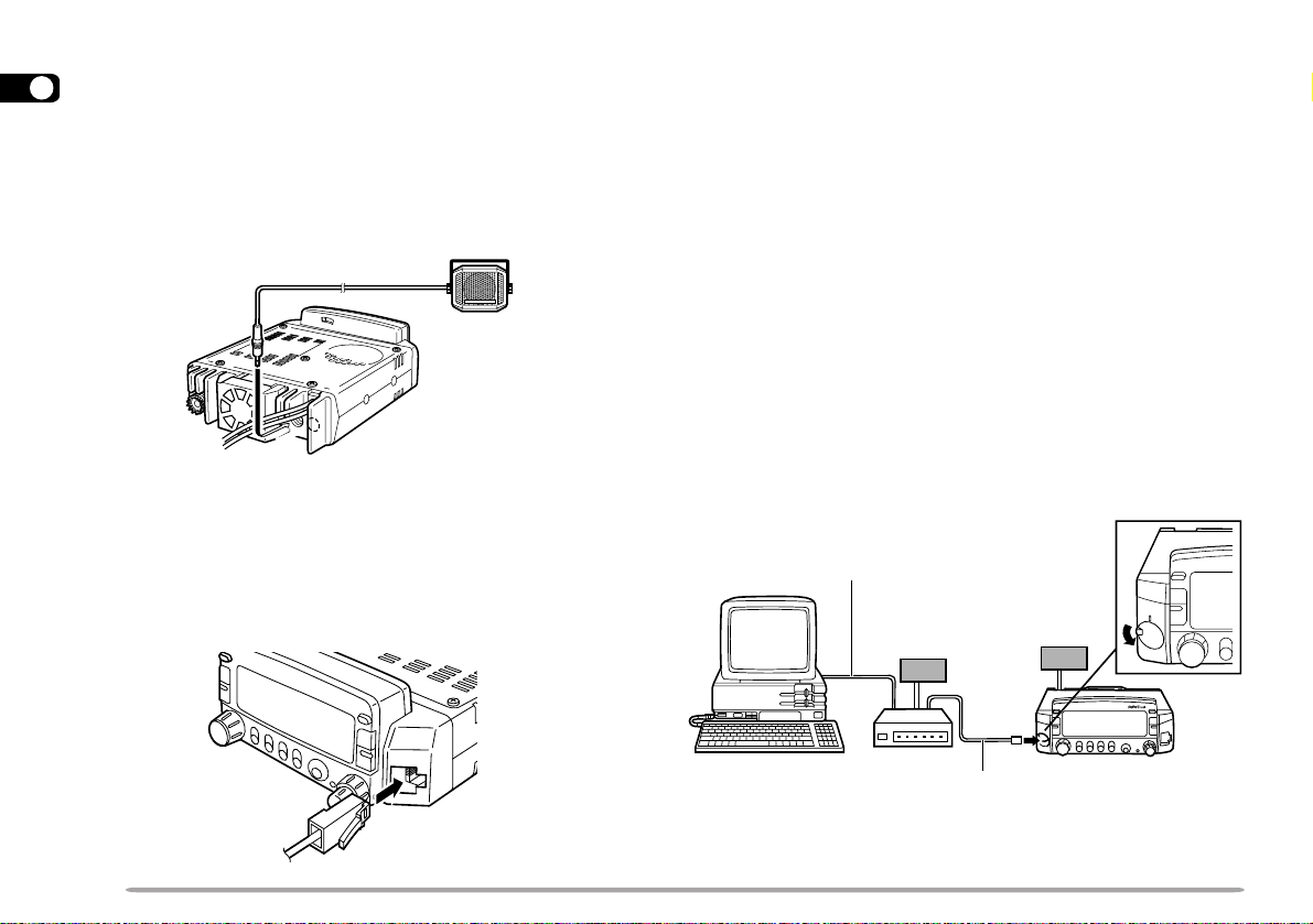
P ACKET EQUIPMENT CONNECTIONS
If you intend to use this transceiver for Packet operation,
you will need the following equipment.
• Personal computer with communications software
• Terminal Node Controller (TNC)
• TNC power supply
• RS-232C cable
• 6-pin mini DIN plug (optional PG-5A)
For the DATA connector pins, refer to “PACKET
OPERATION” {page 61}.
Note:
◆
Do not share a single power supply between the transceiver and the
TNC.
◆
Keep as wide a separation between the transceiver and computer as
practical to reduce noise-pickup by the transceiver.
◆
One end of the optional PG-5A cable has not been connectorized.
Attach the appropriate connector that mates with the TNC connector.
RS-232C cable
TNC power
supply
M
D
U
A
L
B
A
N
D
E
R
T
M
-
G
7
0
7
TNC
PG-5A cable
Transceiver
power supply
TM-G707
6

YOUR FIRST QSO
YOUR FIRST QSO
If you tend to discard instruction manuals along with the
packaging material .....please don’t. The 7 steps given here will
get you on the air in your first QSO right away. So, you can enjoy
the exhilaration that comes with opening a brand new
transceiver.
After trying the rig for a while, settle back in your most
comfortable operating chair with this manual and your favorite
drink for an hour or two. The time spent will be worthwhile.
MC-53DM
Switch ON the DC power supply, then
press the PWR switch.
Turn the VOL and SQL controls to
approximately 9 o’clock.
Press
[BAND]
UHF band.
Turn the Tuning control to select a
frequency.
Press and hold Mic [PTT], then speak
in a normal tone of voice.
Release Mic [PTT] to receive.
Repeat steps and to continue
communication.
to select the VHF or
1
2
3
4
5
6
7
8
9
10
11
12
13
14
15
16
17
18
19
20
21
22
7

GETTING ACQUAINTED
1
BASIC TRANSCEIVER MODES
2
3
This section introduces you to the basic modes you can
select.
4
5
VFO mode
6
Press [VFO] to select. In this mode you can change the
operating frequency using the Tuning control or Mic
7
[UP]/ [DWN].
8
9
10
11
12
13
Memory Recall mode
14
Press [MR] to select. In this mode you can change
15
memory channels, using the Tuning control or Mic [UP]/
16
[DWN], where you stored frequencies and related data.
For further information, refer to “MEMORY CHANNELS”
17
{page 27}.
18
19
20
21
22
Programmable Memory (PM) mode
Press [PM] to select. In this mode you can select the
transceiver environment, by pressing
stored in PM channels {page 36}.
[1]
to
[4]
, that you
Menu mode
Press [MNU] to select. In this mode you can change
Menu Nos. using the Tuning control or Mic [UP]/ [DWN].
For further information, refer to “MENU SET-UP”
{page 19}.
8

Easy Operation mode
Press [MNU]+ POWER ON to select. In this mode only
the basic functions are available and the memory storing
procedures are simplified. You may prefer this mode if
you seldom use functions other than the basic ones. For
further information, refer to “EASY OPERATION”
{page 18}.
2
1
BUTTON FUNCTION DISPLAY
The lower portion of the display has labels that indicate
the current function of each of the 5 front panel buttons.
The Italic font is used to show these 5 buttons in the
description of each operation step. After pressing
pressing
[F]
again or waiting for 10 seconds restores the
basic state.
Basic State
Display Lavels
Labels after
Pressing
[F]
Labels after
Pressing [PM]
Note: After pressing [F], press the appropriate key within approximately
10 seconds, or the Basic State display will be restored.
[F]
,
1
2
3
4
5
6
7
8
9
10
11
12
13
14
15
16
17
18
19
20
21
22
9

FRONT PANEL
1
Note: This section describes only the main functions of the front panel
controls and buttons. For the functions not described here, you will find
2
explanations in the appropriate sections of this manual.
3
4
5
6
7
8
9
10
qq
q CALL button
qq
11
12
13
14
15
16
17
18
19
20
21
22
Recalls the Call channel {page 31}. Also starts or
stops Call/VFO Scan {page 43} when in VFO mode,
or Call/Memory Scan {page 43} when in Memory
Recall mode.
ww
w VFO button
ww
Selects the VFO mode. In this mode you can change
the operating frequency, using the Tuning control or
Mic [UP]/ [DWN]. Also provides:
• VFO Scan start/stop to scan the entire VFO range
{page 40}.
• Program Scan start/stop to scan a programmed range of
frequencies {page 43}.
ee
e MR button
ee
Selects the Memory Recall mode {page 29}. In this
mode you can change memory channels, using the
Tuning control or Mic [UP]/ [DWN] . Also starts or
stops Memory Scan {page 40}.
rr
r Tuning control
rr
Selects:
• Operating frequencies when in VFO mode {page 16}.
• Memory channels when in Memory Recall mode
{page 29}.
• Menu Nos. when in Menu mode {page 19}.
This control is used for various other selections.
tt
t MHz button
tt
Selects the MHz mode. In this mode you can change
the operating frequency in 1 MHz steps or 10 MHz
steps {page 16}, using the Tuning control or Mic
[UP]/ [DWN]. Also starts or stops MHz Scan
{page 41}.
10

yy
y F (Function) button
yy
Allows you to select the different functions that are
available using the multifunction buttons.
uu
u TONE button
uu
Switches the Tone function {page 24} or CTCSS
function {page 46} ON or OFF. Also activates or
deactivates Automatic Tone frequency ID {page 47}.
ii
i REV button
ii
Switches the transmit frequency and receive
frequency when operating with a standard transmit
offset {page 23} or an odd-split memory channel
{page 28}.
oo
o LOW button
oo
Selects High, Medium, or Low transmit output power
{page 17}.
!0!0
!0 BAND button
!0!0
Selects the VHF or UHF band. On some versions,
also selects the 118 MHz band.
!1!1
!1 DIM button
!1!1
Selects the display illumination from 5 levels,
including OFF {page 56}.
!2!2
!2 VOL control
!2!2
When turned, adjusts the level of receive audio from
the speaker {page 15}.
!3!3
!3 SQL control
!3!3
When turned, adjusts the squelch threshold level
{page 15}. This allows you to mute speaker output
while no stations are being received
1
2
3
4
5
6
7
8
9
10
11
12
13
14
15
16
17
18
19
20
21
22
11

1
2
3
4
5
6
!4!4
!4 MNU button
!4!4
7
Selects the Menu mode {page 19}.
8
9
!5!5
!5 PM button
!5!5
10
11
12
Selects the Programmable Memory mode {page 36}.
!6!6
!6 PWR switch
!6!6
Switches the transceiver ON or OFF {page 15}.
13
!7!7
!7 Microphone connector
!7!7
14
15
16
17
18
19
20
21
22
Insert the 8-pin modular connector plug until the
locking tab “clicks”.
UP
DC 8 V, 200 mA max.
GND
STBY (PTT)
GND (MIC)
MIC
NC: No connection
DWN
!8!8
!8 DATA connector
!8!8
Connect a Terminal Node Controller (TNC) for Packet
operation. Accepts a 6-pin mini DIN plug {page 6}.
REAR PANEL
qq
q Antenna connector
qq
Connect an external antenna {page 5}. When making
test transmissions, connect a dummy load in place of
the antenna. The antenna system or load should
have an impedance of 50 Ω. The TM-G707E accepts
a male N-type connector and other versions accept a
male PL-259 connector. This transceiver has only
one antenna connector because of a built-in duplexer.
ww
w Power Input 13.8 V DC cable
ww
Connect a 13.8 V DC power source. Use the
supplied DC power cable {pages 3 and 4}.
ee
e Speaker jack
ee
If you wish, connect an optional external speaker for
clearer audio. This jack accepts a 3.5 mm (1/8")
diameter, 2-conductor plug. See page 6 for more
information. The right jack is unavailable.
12

MICROPHONE
MC-53DM MC-45
2
DWN UP
3
5
6
4
3
5
6
qq
q UP button
qq
ww
w DWN button
ww
7
12
8
6
Raises or lowers the operating frequency, the
memory channel number, the menu number, etc.
Holding either button down causes the action to be
repeated. Also, switches between values for
functions with multiple choices.
ee
e PTT (Push-to-talk) switch
ee
Press and hold to transmit, then release to receive.
rr
r LOCK switch
rr
Locks all microphone keys except [PTT] and the
DTMF keypad, if equipped.
1
7
8
MIC
VFO MR PFCALL
LOCK
ELECTRET CONDENSER MIC
MADE IN JAPAN
tt
t CALL key
tt
yy
y VFO key
yy
uu
u MR key
uu
Identical to the front panel CALL, VFO and MR
buttons. These keys can be re-programmed, if
desired {page 50}.
ii
i PF key
ii
4
Depending on which function you select by accessing
“PF1” in Menu No. 20 {page 51}, the function of this
key differs. Refer to “PROGRAMMABLE FUNCTION
(PF) KEYS” {page 50}.
oo
o DTMF keypad (MC-53DM only)
oo
The 16-key keypad is used for DTMF functions
{page 48}, or to directly enter a frequency or a
memory channel number {page 54}.
1
2
3
4
5
6
7
8
9
10
11
12
13
14
15
16
17
18
19
20
21
22
13

INDICATORS
1
On the display you will see various indicators that show
what you have selected. Sometimes you may not recall
2
what those indicators mean or how you can cancel the
3
current setting. In such a case, you will find this table
4
very useful.
5
6
7
8
9
10
11
12
13
14
15
16
17
18
19
20
21
22
1
U.S.A./ Canada only
2
TM-G707E only
rotacidnI detceleSuoYtahW
)gniknilB(
1
2
kcoLreviecsnarT
kcoLllA
edomMA.0.oNuneMesU
SSCTC
noitcnufenoT
)zHM6.7–(
esreveR
nacSytiroirP
dnab-ssorC
noitarepO
]F[
, ]zHM[
NO neht
]ENOT[
]ENOT[
,
]F[
,
noitceridtesffosuniM
erom
]F[
,
noitceridtesffosuniM
]F[
,
]F[
,
noitceridtesffosulP
]TFIHS[
erom
]F[
,
]VER[
]F[
, ]UNM[
]F[
,
][
rotacidnI detceleSuoYtahW
rewoPcitamotuA
FFO
otsserPuoYtahW
lecnaC
.21.oNuneMesU
refsnartspb0069.91.oNuneMesU
tpecretnIdecnavdA
]F[
,
otsserPuoYtahW
lecnaC
tnioP
yromemtuo-dekcoL
lennahc
REWOP+]zHM[
]F[
, ]zHM[
lennahcyromeM
atadgniniatnoc
]MID[
.3.oNuneMesU
—
edomtimsnarTciMesaeleR ]TTP[ .
rewoptimsnarthgiHtluafeD
]ENOT[
]TFIHS[
eno:E707G-MT(
]TFIHS[
)
rewop
timsnartmuideM
rewoptimsnartwoL
]TFIHS[
]TFIHS[
,
]F[
,
When you receive a signal:
]WOL[
,
]WOL[
ot
tluafedehttceles
)hgiH(
]WOL[
ehttcelesot
)hgiH(tluafed
eno:E707G-MT(
]TFIHS[
)
• “BUSY” appears when the squelch {page 15} is open.
• The S-meter shows the strength of received signals.
14

OPERATING BASICS
SWITCHING POWER ON/OFF
1 Switch ON the DC power supply.
• If operating mobile, skip this step.
2 Press the PWR switch to switch ON the transceiver.
3 To switch OFF the transceiver, press the PWR switch
again.
• In a fixed installation, after the transceiver has been
switched ON, it can then be switched OFF or ON by
using only the power switch on the DC power supply.
ADJUSTING VOLUME
Turn the VOL control clockwise (or counterclockwise) to
increase (or decrease) the audio level.
ADJUSTING SQUELCH
The purpose of the Squelch function is to silence
background noise output from the speaker (squelch
closed) when no signals are present. When the squelch
level is set correctly, you will hear sound (squelch
opened) only while a station is actually being received.
Turn the SQL control to just eliminate the background
noise when no signal is present.
• As you turn the control clockwise, stronger signals are
required to open the squelch.
Note: The point at which ambient noise on a frequency just disappears,
called the squelch threshold, depends on the frequency.
SELECTING A BAND
Press
[BAND]
to select the VHF or UHF band.
1
2
3
4
5
6
7
8
9
10
11
12
13
14
15
16
17
18
19
20
21
22
15

SELECTING FREQUENCIES
1
■ Tuning Control
2
Using the Tuning control is convenient when you are
3
within easy reach of the transceiver front panel, and
4
the frequencies to be selected are near the current
frequency.
5
1 Press [VFO] to select VFO mode.
6
7
8
9
10
11
12
13
14
15
16
17
18
19
20
21
22
2 Turn the Tuning control clockwise to increase the
frequency or counterclockwise to decrease the
frequency.
• You can also select frequencies via the microphone
keypad (MC-53DM only). See “KEYPAD DIRECT
ENTRY” {page 54}.
• To change frequencies in steps of 1 MHz, press
[MHz] first. Pressing [MHz] again cancels the
1 MHz function.
• To change frequencies in steps of 10 MHz, press
[F]
+[MHz] first; do not press
1 second. Pressing
pressing [MHz] starts the 1 MHz function.
Note: If you cannot select a particular frequency, you need to
change the frequency step size. See “CHANGING FREQUENCY
STEP SIZE” {page 55} for further information.
[F]
[F]
for longer than
cancels the 10 MHz function;
■ Microphone [UP]/ [DWN] Buttons
Using Mic [UP]/ [DWN] for frequency selection is
useful when mobiling or any time you are not
immediately in front of the transceiver.
Press Mic [UP] or [DWN] once to change the
frequency by one step in the direction indicated by
the button.
• Pressing and holding the button causes the frequency to
step repeatedly. Release it to stop the frequency
change.
• To change frequencies in steps of 1 MHz (or 10 MHz),
press [MHz] (or
[F]
MC-53DM
+[MHz]) first.
16

TRANSMITTING
1 When ready to begin transmitting, press and hold Mic
[PTT] and speak in a normal tone of voice.
• “ON AIR” and the RF power meter appear.
• Speaking too close to the microphone, or too loudly,
may increase distortion and reduce intelligibility of your
signal at the receiving station.
• The RF power meter shows the relative transmit output
power.
2 When you finish speaking, release Mic [PTT].
MC-53DM
■ Selecting Output Power
It’s wise, and required by law, to select the lowest
power that allows reliable communication. If
operating from battery power, lower transmit power
will give you more operating time before a charge is
necessary. Reducing power lowers the risk of
interfering with others on the band.
Press
[LOW]
to select high (“H”), medium (“M”), or
low (“L”) power. The default is high.
CAUTION:
◆
DO NOT TRANSMIT WITH HIGH OUTPUT POWER FOR
EXTENDED PERIODS. THE TRANSCEIVER MA Y OVERHEAT
AND MALFUNCTION.
◆
CONTINUOUS TRANSMISSION CAUSES THE HEAT SINK TO
OVERHEAT. NEVER TOUCH THE HEAT SINK WHEN IT MAY BE
HOT .
Note: When the transceiver overheats because of ambient high
temperature or continuous transmission, the protective circuit may
function to lower transmit output power .
1
2
3
4
5
6
7
8
9
10
11
12
13
14
15
16
17
18
19
20
21
22
17

1
If you are a person who has just acquired a ham
2
license and wants to use only the basic functions
3
for now, use Easy Operation mode. Only the
basic functions are available in this mode so you
4
need not worry about studying other functions.
5
When in this mode, you can store a simplex
6
frequency in up to 3 memory channels by just
pressing a single key; the channels are shared by
7
both bands.
8
Press [MNU]+ POWER ON to enter (or exit) Easy
9
Operation mode.
10
2
11
12
1
13
14
Note: Settings made in Easy Operation mode are independent
15
of settings in the normal mode.
16
The available keys and functions in this mode are
listed in the table. The VOL and SQL controls
17
also function.
18
19
20
21
2
3
4
5
13
1
15
16
17
22
6
7
8
9
10
12
11
MC-53DM
18
EASY OPERATION
RWP .reviecsnarteht)FFOro(NOhctiws51
OFV .edomOFVtceles8
RM .edomllaceRyromeMtceles—
1
2
3
WOL .rewoptuptuotimsnartehthctiws71
MID .noitanimulliyalpsidehtegnahc65
ciM NWD .ycneuqerfgnitarepoehtrewol61
14
18
19
ciM PU .ycneuqerfgnitarepoehtesiar61
ciM TTP .timsnart71
ciM LLAC .lennahcllaCehtllacer13
ciM OFV .edomOFVtceles8
ciM RM .edomllaceRyromeMtceles—
ciM FP .dnabtnerrucehtegnahc51
sserP oT
LLAC .lennahcllaCehtllacer13
LLAC
)s1(
zHM .zHM1fospetsniycneuqerfehtegnahc61
gninuT
lortnoc
)s1(1
)s1(2
)s1(3
DNAB .dnabtnerrucehtegnahc51
.lennahcllaC
.ycneuqerfehtegnahc61
.xe;3ro,2,1lennahcyromem
.1lennahcnierots
.xe;derots
]1[
.1lennahcllacerot
ehtniycneuqerfdetcelesyltnerrucehterots
niycneuqerfdetcelesyltnerrucehterots
)s1(]1[
ot
atadfi,3ro,2,1lennahcyromemllacer
egaP
.feR
13
—
—

MENU SET-UP
WHAT IS A MENU?
Many functions on this transceiver are selected or
configured via a software-controlled Menu instead of
physical controls on the transceiver. Once familiar with
the Menu system, you will appreciate the versatility it
offers.
MENU ACCESS
1 Select the desired band.
• For some Menu Nos., you can select a different setting
on each band.
2 Press [MNU] to enter Menu mode.
• The last Menu No. used appears.
3 Turn the Tuning control, or press Mic [UP]/ [DWN], to
select the Menu No.
• “ESC” and “OK” appear as button labels.
• To cancel the selection and restore the previous display,
4 Press
• Depending on Menu Nos., “s” also appears. For the
[ESC]
press
[OK]
subsequent steps, see the appropriate sections in this
manual.
.
.
5 Turn the Tuning control, or press Mic [UP]/ [DWN], to
switch the selection.
6 Press
[OK]
again to complete the setting and exit
Menu mode.
Note: As required, operate keys or the Tuning control in each step within
approximately 10 seconds, or the previous mode will be restored.
1
2
3
4
5
6
7
8
9
10
11
12
13
14
15
16
17
18
19
20
21
22
19

MENU CONFIGURATION
1
Note: For the shaded Menu functions, select the appropriate band (VHF or UHF) before entering Menu mode.
2
3
4
5
6
7
8
9
10
11
12
13
14
15
16
17
18
19
20
21
22
uneM
.oN
0
noitpircseD snoitceleS tluafeD
hctiwSedoMMF/MA
)ylnoadanaC/.A.S.U(
MF/MA egapecnerefereeS 95
1egasseMnO-rewoPegapecnerefereeSDOOWNEK75
2egnahCremmiDotuAFFO/NOFFO65
3tuokcoLlennahCyromeM
1
FFO/NOFFO14
4dohteMllaceRyromeM )ENO(dnabelgniS/)LLA(sdnabllAsdnabllA92
5emaNlennahCyromeM
1
egapecnerefereeS03
6egarotSlennahCMPotuAFFO/NOFFO73
7
tesffOretaepeRcitamotuA
)ylnoeporuE/adanaC/.A.S.U(
FFO/NO NO 52
8 ycneuqerFtesffO zHk05fospetsnizHM59.92~zHM00.00 egapecnerefereeS 32
9
OFVelbammargorP
)stimilrewol/reppU(
01dohteMemuseRnacS )OC(detarepO-reirraC/)OT(detarepO-emiTdetarepO-emiT93
11dohteMnacSytiroirPBedoM/AedoMAedoM54
21)OPA(ffOrewoPcitamotuAFFO/NOFFO25
31)TOT(remiTtuO-emiTsetunim01/5/3setunim0125
41hcleuqSretem-SFFO/NOFFO85
51emiTgnaHhcleuqSretem-S
1
Menu No. 3 and No. 5 are selectable only after a memory channel has been recalled.
2
Menu No. 15 is selectable only when S-meter Squelch is ON.
2
FFO/sm005/sm052/sm521FFO85
.feR
egaP
XRrewol/reppU
dnabehtnoelbatcelesseicneuqerF
nostimilycneuqerf
35
dnabeht
20

uneM
.oN
noitpircseD snoitceleS tluafeD
61emuloVpeeBFFO/).xam(7~).nim(1leveL5leveL65
71rezisehtnySecioV
81hctiwSnoitcnuFECIOV/MID
1
1
ECIOV/MIDMID36
FFO/esenapaJ/hsilgnEhsilgnE36
91etaRrefsnarTataDspb0069/spb0021spb002116
32~02syeKnoitcnuFelbammargorPegapecnerefereeSgnittesresU15
52,42desuyltnerructoN
62
72
)ylnoE707G-MT(
lortnoCenohporciM
82
83~92
1
Menu No. 17 and No. 18 are selectable only when the optional VS-3 is installed.
dloHtimsnarTenoTzH0571
)ylnoadanaC/.A.S.U(
senoTnoitamrifnoCdapyeKciM
)ylnoadanaC/.A.S.U(
egarotSrebmuNFMTD
)ylnoadanaC/.A.S.U(
FFO/NOFFO15
FFO/NOFFO06
FFO/NOFFO84
egapecnerefereeS94
.feR
egaP
1
2
3
4
5
6
7
8
9
10
11
12
13
14
15
16
17
18
19
20
21
22
21

OPERATING THROUGH REPEATERS
1
Repeaters are often installed and maintained by radio
2
clubs, sometimes with the cooperation of local
3
businesses involved in the communications industry.
4
Compared to simplex communication, you can usually
transmit over much greater distances by using a
5
repeater. Repeaters are typically located on a mountain
6
top or other elevated location. Often they operate at
higher ERP (Effective Radiated Power) than a typical
7
station. This combination of elevation and high ERP
8
allows communications over considerable distances.
9
10
11
12
13
14
15
16
17
18
19
20
21
22
TX: 144.725 MHz
TX tone: 88.5 Hz
RX: 145.325 MHz
TX: 144.725 MHz
TX tone: 88.5 Hz
RX: 145.325 MHz
REPEATER ACCESS
Most amateur radio voice repeaters use a separate
receive and transmit frequency. You can set a separate
transmit frequency by selecting the offset frequency and
offset direction with respect to the receive frequency. In
addition, some repeaters may require the transceiver to
transmit a tone before the repeater can be used. To
transmit this required tone, activate the Tone function
and select a tone frequency.
The required offset direction, offset frequency, and tone
frequency depend on the repeater you are accessing.
Consult your local repeater reference.
Flow Chart for Repeater Access
Select a band.
Select a receive frequency.
Select an offset direction.
Select an offset frequency.
Activate the Tone function, if necessary.
Select a tone frequency, if necessary.
Press and hold Mic [PTT].
22

■ Selecting Offset Direction
Select whether the transmit frequency will be higher
(+) or lower (–) than the receive frequency.
1 Select the desired band.
2 Press
Note:
◆
◆
TM-G707E Only: If you select “- -” for the offset direction, you cannot
change the default offset frequency (7.6 MHz).
[F], [SHIFT]
• Each time you repeat this key operation, the offset
direction changes as shown below.
TM-G707A/E
(VHF)
TM-G707A
(UHF)
TM-G707E
(UHF)
If the offset transmit frequency falls outside the allowable transmit
frequency range, transmitting is inhibited. Use one of the
following methods to bring the transmit frequency into the
allowable range:
•
Move the receive frequency further inside the band.
•
Change the offset direction.
While using an odd-split memory channel or transmitting, you
cannot change the offset direction.
.
Simplex
Simplex
+
+
−
−
−−
■ Selecting Offset Frequency
Select how much the transmit frequency will be offset
from the receive frequency. The default offset
frequency on the VHF band is 600 kHz no matter
which market version; the default on the UHF band is
5 MHz (TM-G707A) or 1.6 MHz (TM-G707E).
1 Select the desired band.
2 Press [MNU] to enter Menu mode.
3 Select Menu No. 8 (OFS).
4 Press
[OK]
, then select the appropriate offset
frequency.
• The selectable range is from 00.00 MHz to
29.95 MHz in steps of 50 kHz.
2
1
5 Press
[OK]
again to complete the setting and exit
Menu mode.
Note: After changing the offset frequency, the new offset frequency
will also be used by Automatic Repeater Offset.
1
2
3
4
5
6
7
8
9
10
11
12
13
14
15
16
17
18
19
20
21
22
23

■ Activating Tone Function
1
1 Select the desired band.
2
2 Press
3
4
5
[TONE]
• Each time you press
as shown below.
to activate the Tone function.
No Indicator
6
7
8
TM-G707E Only: When you access repeaters that require 1750 Hz
9
tones, you need not activate the Tone function. No matter which
10
11
12
13
14
15
16
17
selection you make here, pressing the Mic PF key assigned the
1750 Hz T one function {page 51} causes the transceiver to transmit
1750 Hz tones.
■ Selecting a Tone Frequency
1 Select the desired band.
2 Press
3 Press
[TONE]
to activate the Tone function.
[F], [T.SEL]
• The current tone frequency appears and blinks. The
default is 88.5 Hz.
18
19
20
21
22
4 Turn the Tuning control, or press Mic
1 2
[UP]/ [DWN], to select a tone frequency.
24
.
[TONE]
Tone
(“T”)
, the selection changes
CTCSS
(“CT”)
5 Press
TM-G707E Only: To transmit a 1750 Hz tone, assign the 1750 Hz
Tone function to one of the Programmable Function (PF) keys of the
microphone {page 51}.
Note: If you store tone settings in memory channels, you need not
make the settings every time. Recalling the memory channels will
restore the tone settings which you make this time. Refer to
“MEMORY CHANNELS” {page 27}.
[OK]
to complete the setting.
.oN
.qerF
.oN
)zH(
.qerF
.oN
)zH(
.qerF
.oN
)zH(
.qerF
)zH(
100.76114.79125.631138.291
209.17210.001223.141235.302
304.47315.301322.641337.012
400.77412.701424.151431.812
507.97519.011527.651537.522
605.28618.411622.261636.332
704.58718.811729.761738.142
805.88810.321828.371833.052
905.19913.721929.971
018.49028.131032.681
U.S.A./ Canada Only: Use Nos. 01 to 38 shown in the table above
when selecting tone frequencies via Keypad Direct Entry {page 55}.

■ Automatic Repeater Offset
(U.S.A./ Canada/ Europe Only)
This function automatically selects an offset direction
and activates the Tone function, according to the
frequency that you select on the VHF band. The
transceiver is programmed for offset direction as
shown below. To obtain an up-to-date band plan for
repeater offset direction, contact your national
Amateur Radio association.
U.S.A. and Canada versions
This complies with the standard ARRL band plan.
144.0 145.5 146.4 147.0 147.6
145.1 146.0 146.6 147.4 148.0 MHz
−−
+
S: Simplex
+
SS
S
European versions
144.0
S
S: Simplex
Note: Automatic Repeater Offset does not function when Reverse or
CTCSS is ON. However, pressing [REV] after Automatic Repeater
Offset has selected an offset (split) status, exchanges the receive and
transmit frequencies.
–
−
S
146.0 MHz145.8145.6
S
1 Select the VHF band.
2 Press [MNU] to enter Menu mode.
3 Select Menu No. 7 (ARO).
4 Press
[OK]
, then switch the function ON (default)
or OFF.
2
1
5 Press
[OK]
again to complete the setting and exit
Menu mode.
1
2
3
4
5
6
7
8
9
10
11
12
13
14
15
16
17
18
19
20
21
22
25

REVERSE FUNCTION
1
After setting a separate receive and transmit frequency,
you can exchange these frequencies using the Reverse
2
function. While using a repeater, this function allows you
3
to check the signal strength of a station accessing the
4
repeater. If the station’s signal is strong, move to a
simplex frequency to continue the contact and free up
5
the repeater.
6
Press
[REV]
7
(or OFF).
8
• “R” appears when the function is ON.
9
10
11
12
Note:
13
◆
14
15
16
17
If pressing [REV] places the transmit frequency outside the allowable
transmit frequency range, then pressing Mic [PTT] causes an error
beep to sound; transmission is inhibited.
◆
If pressing [REV] places the receive frequency outside the receive
frequency range, an error beep sounds and no reversal occurs.
◆
Automatic Repeater Offset does not function while Reverse is ON.
◆
You cannot switch Reverse ON or OFF while transmitting.
18
19
20
21
22
to switch the Reverse function ON
26

MEMORY CHANNELS
In memory channels, you can store frequencies and
related data that you often use. Then you need not
reprogram those data every time. You can quickly recall
wanted channels by simple operation. A total of
180 memory channels are available for VHF and UHF.
You can also store a name for each memory channel.
For more information, see “NAMING MEMORY
CHANNELS” {page 30}.
SIMPLEX & REPEATER OR ODD-SPLIT MEMORY
CHANNEL?
You can use each memory channel as a simplex &
repeater channel or odd-split channel. Store only one
frequency to use as a simplex & repeater channel or two
separate frequencies to use as an odd-split channel.
Select either application for each channel depending on
the operations you have in mind.
Simplex & repeater channel allows:
• Simplex frequency operation
• Repeater operation with a standard offset
(If an offset direction is stored)
Odd-split channel allows:
• Repeater operation with a non-standard offset
Note: Not only can you store data in memory channels, but you can also
overwrite existing data with new data.
The data listed below can be stored in each memory
channel:
retemaraP
&xelpmiS
retaepeR
ycneuqerfevieceR
seY
ycneuqerftimsnarTseY
ycneuqerfenoTseYseY
NOenoTseYseY
ycneuqerfSSCTCseYseY
NOSSCTCseYseY
ezispetsycneuqerFseYseY
noitceridtesffOseYA/N
NOesreveRseYA/N
tuokcollennahcyromeMseYseY
emanlennahcyromeMseYseY
Yes: Can be stored in memory.
N/A: Not applicable
1
2
3
tilps-ddO
4
seY
5
6
7
8
9
10
11
12
13
14
15
16
17
18
19
20
21
22
27

STORING SIMPLEX FREQUENCIES OR STANDARD
REPEATER FREQUENCIES
1
2
1 Press [VFO] to select VFO mode.
3
2 Press [BAND] to select the desired band.
4
3 Turn the Tuning control, or press Mic [UP]/ [DWN], to
select the desired frequency.
5
• You can also enter digits directly from the microphone
6
7
8
9
10
11
12
13
14
15
16
17
18
19
20
21
22
keypad (MC-53DM only). See page 54.
4 If storing a standard repeater frequency, select the
following data:
Offset direction {page 23}
Tone ON, if necessary {page 24}
Tone frequency, if necessary {page 24}
• If storing a simplex frequency, you may select other
related data (CTCSS ON, CTCSS freq. etc.).
5 Press
[F]
.
• A memory channel number appears.
• A triangle icon appears above the memory channel
number if the channel already contained data.
6 Turn the Tuning control, or press Mic [UP]/ [DWN], to
select the desired memory channel (within approx.
10 seconds).
7 Press [MR].
• The selected frequency and related data are stored in
the memory channel.
28
STORING ODD-SPLIT REPEATER FREQUENCIES
Some repeaters use a receive and transmit frequency
pair with a non-standard offset. To access those
repeaters, store two separate frequencies in a memory
channel. You then can operate on those repeaters
without changing the offset programming in the Menu.
1 Select the appropriate receive frequency by using
steps 1 to 6 (not 7) given for simplex or standard
repeater frequencies.
• If necessary, select Tone ON {page 24} and tone
frequency {page 24}.
2 Press [MR] (1 s).
• “–” and “+” appear.
3 Select the appropriate transmit frequency (within
approx. 10 seconds).
4 Press [MR].
• The selected transmit frequency is stored in the memory
channel.
Note:
◆
When you recall an odd-split memory channel, “–” and “+” appear on
the display. Press [REV] to display the transmit frequency.
◆
In step 2 you cannot use Mic [MR], nor Mic [PF] programmed with
Memory Recall.
◆
Transmit Offset status and Reverse status are not stored in an
odd-split memory channel.

RECALLING MEMORY CHANNELS
1 Press [MR] to enter Memory Recall mode.
• The memory channel used last is recalled.
2 Turn the Tuning control, or press Mic [UP]/ [DWN], to
select the desired memory channel.
• You can also recall memory channels by directly
entering numeric digits via the microphone keypad
(MC-53DM only). See page 54.
• You cannot recall empty memory channels.
• To restore VFO mode, press [VFO].
You may want to recall only memory channels that store
frequencies of the current band. Access Menu No. 4
(MR) to select “ONE”. The default is “ALL”.
ONE: Recalls only memory channels of the current
band.
ALL: Recalls all programmed memory channels. For
example, allows you to recall a VHF frequency
channel when operating the UHF band.
Note:
◆
When you recall an odd-split memory channel, “–” and “+” appear on
the display. Press [REV] to display the transmit frequency.
◆
After recalling a memory channel, you may program data such as
Tone or CTCSS. These settings, however, are cleared once you
select another channel or the VFO mode. To permanently store the
data, overwrite the channel contents {page 28}.
CLEARING MEMORY CHANNELS
1 Recall the desired memory channel.
2 Switch OFF the power to the transceiver.
3 Press [MHz]+ POWER ON.
• A confirmation message appears.
2
1
4 Press
[OK]
.
• The contents of the selected memory channel are
erased.
1
2
3
4
5
6
7
8
9
10
11
12
13
14
15
16
17
18
19
20
21
22
29

NAMING MEMORY CHANNELS
1
You can name memory channels using up to
7 alphanumeric characters. When you recall a named
2
memory channel, its name appears on the display
3
instead of the stored frequency. Names can be
4
callsigns, repeater names, cities, names of people, etc.
5
Note: You can also name the Priority channel, but you cannot name the
Call, L1 to L6, nor U1 to U6 channels.
6
1 Recall the desired memory channel.
7
2 Press [MNU] to enter Menu mode.
8
3 Select Menu No. 5 (MEM.NAME).
9
10
11
12
13
14
4 Press
15
16
17
18
19
20
21
22
5 Turn the Tuning control, or press Mic [UP]/ [DWN], to
[OK]
.
• The first digit blinks.
• If you recall a memory channel that has a name stored,
the last digit blinks.
select the first digit.
• You can select “0” to “9”, “A” to “Z”, “–”, “/ ”, or a space.
• To enter a dot after the digit, press [MR]. Pressing [MR]
again clears the dot.
6 Press
• The second digit blinks.
ss
[
s
]
.
ss
7 Repeat steps 5 and 6 to enter up to 7 digits.
• After selecting the 7th digit, you need not press
tt
[
t
• To re-enter the preceding digit, press
• To clear all digits and move back to the first digit, press
[VFO].
8 Press
[OK]
to complete the setting and exit Menu
tt
]
ss
[
s
]
.
ss
.
mode.
Note:
◆
You can assign names only to memory channels in which you have
stored frequencies and related data.
◆
The stored names can be overwritten by repeating steps 1 to 8.
◆
The stored names also are erased by clearing memory channels.
SWITCHING MEMORY NAME/ FREQUENCY DISPLAY
After storing memory names, you can switch the display
between memory names and frequencies. You may
sometimes want to confirm frequencies stored in named
memory channels.
1 Press [MR] to enter Memory Recall mode.
2 Press [MHz] to switch between memory name and
frequency display.
30

CALL CHANNEL
The Call channel can be used to store any frequency
and related data that you will recall often. The Call
channel also can be programmed either as a simplex &
repeater or odd-split channel. No matter what mode the
transceiver is in, the Call channel can always be
selected quickly. You may want to dedicate the Call
channel as an emergency channel within your group. In
this case, the Call/VFO scan {page 43} will be useful.
The default frequency stored in the Call channel is
shown below:
noisreV FHV FHU
adanaC/.A.S.UzHM000.441zHM000.044
lareneG/eporuEzHM000.441zHM000.034
The contents of the Call channel cannot be deleted;
however, you can overwrite old data with new data as
described in the following section.
■ Recalling the Call Channel
1 Select the desired band.
2 Press [CALL] to recall the Call channel.
• “C” appears.
■ Changing Call Channel Contents
1 Select the desired band.
2 Select the desired frequency and related data
(Tone, CTCSS, etc.).
• When you program the Call channel as an odd-split
channel, select a receive frequency.
3 Press
[F]
, [CALL].
• The selected frequency and related data are stored
in the Call channel.
• The previous mode is restored.
• When programming as an odd-split channel, press
[F]
, [CALL] (1 s) instead. “–” and “+” appear.
To use as an odd-split channel, proceed to the next
step.
4 Turn the Tuning control, or press Mic [UP]/
[DWN], to select the desired transmit frequency.
5 Press [CALL] again.
• The selected transmit frequency is stored in the Call
channel, and the previous mode is restored.
Note:
◆
Transmit Offset status and Reverse status are not stored in an
odd-split Call channel.
◆
To store data other than frequencies, select the data in step 2
not step 4.
1
2
3
4
5
6
7
8
9
10
11
12
13
14
15
16
17
18
19
20
21
22
• To restore the previous mode, press [CALL] again.
31

MEMORY ➡ VFO TRANSFERS
1
Transferring the contents of a memory channel or the
Call channel to the VFO can be useful if you want to
2
search for other stations or a clear frequency, near the
3
selected memory channel or Call channel frequency.
4
1 Recall the desired memory channel or the Call
5
channel.
6
2 Press
7
8
9
Note:
10
◆
11
◆
12
13
14
15
16
17
18
19
20
21
22
[F]
, [VFO].
• The entire contents of the memory channel or the Call
channel are copied to the VFO. VFO mode is selected
after the transfer is completed.
A transmit frequency from an odd-split memory channel or odd-split
Call channel is not transferred to the VFO. To transfer a transmit
frequency, press [REV], then press [F], [VFO].
Lockout status and memory names are not copied from a memory
channel to the VFO.
CHANNEL DISPLAY FUNCTION
When this function is switched ON, the transceiver
displays only a memory channel number instead of a
frequency.
Press
[LOW]
(or OFF).
When in Channel Display mode, you cannot use the
following functions:
• VFO Select
• Programmable Memory
Recall
• Memory Channel Store
• Memory ➞ VFO Transfer
• Freq. Step Size Change
• Easy Operation Select
• Programmable Memory
Reset
Note:
◆
You cannot switch this function ON if you have stored frequencies in
no memory channels.
◆
When in Channel Display mode, you may want to recall only memory
channels of the desired band. Before pressing [LOW]+ POWER ON,
select “ONE” in Menu No. 4 (MR), then select the desired band.
+ POWER ON to switch this function ON
2
1
• MHz Function Select
• Programmable Memory
Store
• Call Channel Store
• Memory Channel Clear
• VFO Scan
• Partial/ Full reset
32

INITIALIZING MEMORY
If your transceiver seems to be malfunctioning,
initializing the transceiver may resolve the problem.
In addition, doing Full Reset is a quick way to clear all
memory channels; however, you then need to
re-program memory channels after initialization.
Note: While using the Channel Display or All Lock function, you cannot
do Partial Reset nor Full Reset.
VHF Band Defaults
noisreV ycneuqerFOFV
/.A.S.U
adanaC
/eporuE
lareneG
UHF Band Defaults
noisreV ycneuqerFOFV
/.A.S.U
adanaC
/eporuE
lareneG
ycneuqerF
petS
zHM000.441zHk5zH5.88
zHM000.441zHk5.21zH5.88
ycneuqerF
petS
zHM000.044zHk52zH5.88
zHM000.034zHk52zH5.88
enoT
ycneuqerF
enoT
ycneuqerF
■ Partial Reset (VFO)
Use to initialize all settings except the memory
channels, the Call channel, the PM channels, and
Memory Channel Lockout.
1 Press [VFO]+ POWER ON.
• A confirmation message appears.
1
• To quit resetting, press any key other than
2 Press
[OK]
.
2
[OK]
.
■ Full Reset (Memory)
Use to initialize all settings that you have customized.
1 Press [MR]+ POWER ON.
• A confirmation message appears.
2
1
• To quit resetting, press any key other than
2 Press
Note: You can also do Partial Reset or Full Reset by pushing the RESET
switch on the transceiver {page 73}.
[OK]
.
[OK]
.
33
1
2
3
4
5
6
7
8
9
10
11
12
13
14
15
16
17
18
19
20
21
22

PROGRAMMABLE MEMORY (PM)
1
Programmable Memory (PM) allows you to store virtually
2
all settings currently set on the transceiver. So you can
3
quickly recall exactly the same environment later. This
transceiver provides 4 PM channels. If you are the type
4
of person who likes the many features offered by modern
5
transceivers, but dislikes remembering how to make all
the necessary settings, you will find Programmable
6
Memory particularly useful.
7
8
PROGRAMMABLE INFORMATION
9
The following programmable settings are shared by the
10
VHF and UHF bands:
11
12
13
14
15
16
17
18
19
20
21
22
tceleSdnaB dohtemllaceRyromeM
dohtemnacSyiroirP ffOrewoPcitamotuA
remiTtuO-emiT remmiDyalpsiD
egnahCremmiDotuA emulovpeeB
etarrefsnartataD
dohtememusernacS hcleuqSretem-S
dapyekenohporciM
/.A.S.U(enotnoitamrifnoc
)ylnoadanaC
The following settings can be separately stored for the
VHF and UHF bands:
ycneuqerfOFV edomOFV
edomllaceRyromeM edomlennahCllaC
ezispetsycneuqerF rewoptuptuotimsnarT
ycneuqerfenoT ycneuqerfSSCTC
NOenoT NOSSCTC
noitceridtesffO ycneuqerftesffO
tesffOretaepeRcitamotuA NOesreveR
timilycneuqerfreppU
)OFVelbammargorProf(
tnioPtpecretnIdecnavdA
timsnarTenoTzH0571
)ylnoE707G-MT(dloH
edomMF/MA
timilycneuqerfrewoL
)OFVelbammargorProf(
)ylnoadanaC/.A.S.U(
34

APPLICATION EXAMPLES
The following are examples of how you might use Programmable Memory. These examples may not represent
applications useful to you, but you will understand the flexibility of this function.
You share your transceiver with other members in
your family or club. However, each individual has
personal preferences for how they like to set various
functions. You have to keep changing many settings
each time you use the transceiver.
While operating mobile on the way to work every
morning, you prefer a silent transceiver that does not
interrupt the morning calm. In addition, you feel that a
bright display is a waste of electricity in sunlight.
At night when driving home, you realize the Beep
function truly serves a purpose and you acknowledge
it is nice to see a bright display after dark.
You cannot figure out how you can make the
transceiver exit the current mode.
Situation 1
Situation 1
Situation 2
Situation 2
Situation 3
Situation 3
Because 4 PM channels are available, up to 4
persons can separately program the transceiver and
store their customized environment. Then each
person can quickly change to his or her favorite
settings, simply by recalling a PM channel.
It is too much trouble to change back the settings
after somebody else has reconfigured them. So this
application may avoid having a feature-rich
transceiver but never using many useful features.
In two PM channels, store the same operating data
such as frequency, offset, tone, etc., and store
different settings for the Display Dimmer and Beep
functions. Then you can quickly recall the best
settings for day or night operating.
Simply recall PM channel 1 that contains an exact
copy of the transceiver default environment. You will
not lose the contents of any memory channels.
Solution
Solution
Solution
Solution
Solution
Solution
1
2
3
4
5
6
7
8
9
10
11
12
13
14
15
16
17
18
19
20
21
22
35

STORING DATA IN PM CHANNELS
1
1 Confirm that the following conditions have been
satisfied:
2
• The transceiver is in the receive mode.
3
• Scan is not being used.
4
• Microphone Control is OFF.
5
2 Select the desired band.
6
3 Select the desired frequency and related data (Tone,
7
CTCSS, etc.) using VFO mode.
8
4 If required, select another band, then select the
9
desired frequency and related data.
10
5 Press
11
12
13
14
15
16
6 Press
17
18
19
20
21
22
[F]
, [PM].
• The PM channel numbers appear and blink.
2
1
[1]
to
[4]
corresponding to the desired PM
channel.
• The selected frequency and related data are stored in
the PM channel.
RECALLING PM CHANNELS
1 Press [PM].
• The PM channel numbers appear.
2 Press
Note: You cannot recall a PM memory channel while transmitting.
[1]
to
[4]
corresponding to the desired PM
channel.
• The contents of the selected channel are recalled.
• The selected channel number appears and slowly
blinks.
• To exit PM Recall mode, press [PM],
[PM OFF]
.
36

AUTO PM CHANNEL STORAGE
After you recalled a PM channel, this function
automatically overwrites the current PM channel with the
present operating environment when:
• You recall another PM channel.
• You press [PM],
• You switch OFF the transceiver.
[PM OFF]
Use the following procedures to activate this function:
1 Press [MNU] to enter Menu mode.
2 Select Menu No. 6 (PM.AT).
3 Press
4 Press
[OK]
, then switch the function ON (or OFF).
2
[OK]
again to complete the setting and exit
Menu mode.
.
1
RESETTING PROGRAMMABLE MEMORY
Use this procedure to reset the PM channels to the
factory defaults.
1 Press [CALL]+ POWER ON.
• A confirmation message appears.
1
• To quit resetting, press any key other than
2 Press
[OK]
.
2
[OK]
.
1
2
3
4
5
6
7
8
9
10
11
12
13
14
15
16
17
18
19
20
21
22
37

1
Scan is a useful feature for hands-off monitoring of your
2
favorite frequencies. After becoming comfortable with
3
how to use all types of Scan, the monitoring flexibility
gained will increase your operating efficiency.
4
5
6
7
0
7
G
M
T
R
E
D
N
A
B
L
A
U
D
M
F
7
D
O
O
W
N
E
K
438.525 MHz
8
9
10
11
12
13
Stop
14
15
16
Note:
◆
17
18
19
20
21
Remember to adjust the squelch threshold level before using Scan.
◆
While using CTCSS, Scan stops for any signal received; however,
the squelch opens only for signals that contain the same CTCSS
tone that is selected on your transceiver.
◆
When using S-meter Squelch, Scan stops when the received signal
strength matches or exceeds the S-meter setting. Scan resumes
2 seconds after the signal level drops below the S-meter setting.
22
SCAN
This transceiver provides the following conventional
scans in addition to “Priority Scan” {page 44} that may
be new to you:
epyTnacS egnaRnacS
nacSOFV
nacSyromeM
7
0
7
G
M
T
R
E
D
N
A
B
L
A
U
D
M
F
D
O
O
W
N
E
K
nacSzHMegnarzHM1nihtiwseicneuqerfllA
nacSmargorP
nacSOFV/llaC
dnab
slennahc
dnabehtnodetceles
ycneuqerf
yromeM/llaC
nacS
desutsallennahc
ehtnoelbanutseicneuqerfllA
yromemehtniderotsseicneuqerF
egnarehtniseicneuqerfllA
OFVtnerrucehtsulplennahcllaC
yromemehtsulplennahcllaC
38

SCAN RESUME METHODS
Before using Scans other than Priority Scan, it’s
necessary to decide under what condition you want your
transceiver to continue scanning after detecting and
stopping for a signal. You can choose Time-Operated
mode or Carrier-Operated mode. The default is TimeOperated mode.
• Time-Operated mode
Your transceiver stops scanning when detecting a signal,
remains there for approximately 5 seconds, and then
continues to scan even if the signal is still present.
• Carrier-Operated mode
Your transceiver stops scanning when detecting a signal
and remains on the same frequency until the signal drops
out. There is a 2 second delay between signal drop-out and
scan resumption to allow time for any responding stations to
begin transmitting.
Note: To temporarily stop scanning and monitor weak signals, press and
hold the Mic PF key assigned the Monitor function {page 51}. Release
the key to resume scanning.
■ Selecting Scan Resume Method
1 Press [MNU] to enter Menu mode.
2 Select Menu No. 10 (SCAN).
3 Press
[OK]
, then select Time-Operated (default)
or Carrier-Operated.
2
1
4 Press
[OK]
again to complete the setting and exit
Menu mode.
1
2
3
4
5
6
7
8
9
10
11
12
13
14
15
16
17
18
19
20
21
22
39

VFO SCAN
1
VFO Scan allows you to scan all frequencies from the
lowest frequency to the highest frequency on the band.
2
The current frequency step size {page 55} is used.
3
4
5
6
7
8
9
10
11
12
13
14
15
16
17
18
19
20
21
22
1 s
1 Select the desired band.
2 Press [VFO] (1 s).
• The 1 MHz decimal blinks while scanning is in progress.
• Scan starts at the frequency currently displayed.
• To reverse the scan direction, turn the Tuning control
clockwise (upward scan) or counterclockwise
(downward scan), or press Mic [UP]/ [DWN].
3 To quit VFO Scan, press any key other than [MHz]
and Mic [UP]/ [DWN].
Note: The squelch must be closed for Scan to function.
MEMORY SCAN
Memory Scan allows all memory channels containing
data to be scanned.
1 s
1 Press [MR] (1 s).
• The 1 MHz decimal blinks while scanning is in progress.
• Scan starts with the channel last recalled.
• To reverse the scan direction, turn the Tuning control
clockwise (upward scan) or counterclockwise
(downward scan), or press Mic [UP]/ [DWN].
2 To quit Memory Scan, press any key other than Mic
[UP]/ [DWN].
Note:
◆
At least 2 or more memory channels must contain data and must not
be locked out.
◆
The squelch must be closed for Scan to function.
◆
The L1 to L6 and U1 to U6 memory channels and the priority channel
are not scanned.
◆
You can also start Memory Scan when in Channel Display mode.
While Scan is being interrupted, the channel number blinks.
◆
If you select “ONE” using Menu No. 4 (MR), memory channels on
only the current band will be scanned; otherwise, memory channels
on both VHF and UHF bands will be scanned.
40

■ Locking Out Memory Channels
1 s
Memory channels that you prefer not to monitor while
scanning, can be locked out.
1 Recall the desired memory channel.
2 Press [MNU] to enter Menu mode.
3 Select Menu No. 3 (MR.L.O.).
4 Press
5 Press
[OK]
, then switch Lockout ON (or OFF).
2
1
[OK]
again to complete the setting and exit
Menu mode.
When you recall a locked out memory channel, a star
appears above the memory channel.
Note: The L1 to L6 and U1 to U6 memory channels and the priority
channel cannot be locked out.
MHz SCAN
MHz Scan allows you to scan a 1 MHz segment of the
band. The current 1 MHz digit determines the limits of
the scan. For example, if the current frequency is
438.400 MHz, then MHz Scan would scan from
438.000 MHz to 438.975 MHz. The exact upper limit
depends on the step size selected.
1 Select the desired band.
2 Press [VFO] (1 s) to start VFO Scan first.
3 Press [MHz] to start MHz Scan.
• The 1 MHz decimal blinks while scanning is in progress.
• Scan starts at the frequency currently displayed.
• To reverse the scan direction, turn the Tuning control
clockwise (upward scan) or counterclockwise
(downward scan), or press Mic [UP]/ [DWN].
4 To quit MHz Scan, press any key other than [MHz]
and Mic [UP]/ [DWN].
1
2
3
4
5
6
7
8
9
10
11
12
13
14
15
16
17
18
19
20
21
22
41

PROGRAM SCAN
1
Program Scan is identical with VFO Scan except that
you select the frequency range of the scan.
2
3
4
5
6
7
8
9
10
11
12
13
14
15
16
17
18
19
20
21
22
1 s
■ Setting Scan Limits
You can store up to 6 scan ranges in memory
channels L1/U1 to L6/U6.
1 Select the desired band.
2 Select the desired frequency as the lower limit.
3 Press
[F]
.
4 Select a channel in the range from L1 to L6.
5 Press [MR].
• The lower limit is stored in the channel.
6 Select the desired frequency as the upper limit.
8 Select a matching channel in the range from U1 to
U6.
• If you have selected, for example, L3 in step 4,
select U3.
9 Press [MR].
• The upper limit is stored in the channel.
10 To confirm the stored scan limits, press [MR], then
select the L and U channels.
Note:
◆
The lower limit must be lower in frequency than the upper limit.
◆
The lower and upper frequency steps must be equal.
◆
The lower and upper limits must be selected on the same band.
7 Press
42
[F]
.

■ Using Program Scan
1 Select a frequency equal to or between the
programmed scan limits.
2 Press [VFO] (1 s).
• The 1 MHz decimal blinks while scanning is in
progress.
• Scan starts at the frequency currently displayed.
• To reverse the scan direction, turn the Tuning
control clockwise (upward scan) or counterclockwise
(downward scan), or press Mic [UP]/ [DWN].
3 To quit Program Scan, press any key other than
[MHz] and Mic [UP]/ [DWN].
Note:
◆
The squelch must be closed for Scan to function.
◆
If the frequency step of the current VFO frequency differs from
that of the programmed frequencies, you cannot use Program
Scan.
◆
If the frequency steps of the lower limit and upper limit differ, you
cannot use Program Scan.
◆
If the current VFO frequency is within more than one
programmed scan range, the range stored in the smallest
channel numbers is used.
CALL/VFO SCAN
Use Call/VFO Scan to monitor both the Call channel and
the current VFO frequency on the selected band.
1 Press [VFO] to select VFO mode.
2 Select the desired band.
3 Select the desired frequency.
4 Press [CALL] (1 s) to start Call/VFO Scan.
• The 1 MHz decimal blinks while scanning is in progress.
5 To quit Call/VFO Scan, press any key other than Mic
[UP]/ [DWN].
CALL/MEMORY SCAN
Use Call/Memory Scan to monitor both the Call channel
and the desired memory channel.
1 Recall the desired memory channel.
2 Press [CALL] (1 s) to start Call/Memory Scan.
• The 1 MHz decimal blinks while scanning is in progress.
• The Call channel on the same band as of the selected
memory channel is used for Scan.
3 To quit Call/Memory Scan, press any key other than
Mic [UP]/ [DWN].
Note: The memory channel last used is scanned even if it has been
locked out.
1
2
3
4
5
6
7
8
9
10
11
12
13
14
15
16
17
18
19
20
21
22
43

PRIORITY SCAN
1
You may sometimes want to monitor your favorite
frequency on one band while operating on another band.
2
Use Priority Scan. This Scan always monitors your
3
favorite frequency in the background. When receiving
4
signals on your specific frequency, the transceiver
immediately recalls that frequency on the display and
5
allows you to use it for QSO. First store your favorite
6
frequency in the Priority channel and select one of the
two Priority Scan methods.
7
Note: If you do not operate any control or key for 3 seconds after signals
8
drop, the transceiver resumes Priority Scan.
9
10
11
12
13
14
15
16
17
18
19
20
21
22
7
0
7
G
M
T
R
E
D
N
A
B
L
A
U
D
M
F
D
O
O
W
N
E
K
4
4
1
D
O
O
W
N
E
K
■ Storing Frequency in Priority Channel
1 Select the desired band.
2 Select the desired frequency.
3 Press
[F]
.
• A memory channel number appears.
4 Select the Priority channel (“Pr”).
z
H
M
0
5
.9
7
0
7
G
-
M
T
R
E
D
N
A
B
L
A
U
D
M
F
5 Press [MR].
Note: Not only can you store data in the Priority channel, but you
can also overwrite existing data with new data.
44

■ Selecting Priority Scan Method
This transceiver prepares the following two modes for
Priority Scan. Use mode B when you do not want
Priority Scan to disrupt your current QSO.
Mode A: Monitors the Priority channel every 3 seconds no
Mode B: Monitors the Priority channel every 3 seconds
matter whether or not signals are being received
on the current operating frequency.
only when no signals are present on the current
operating frequency.
1 Press [MNU] to enter Menu mode.
2 Select Menu No. 11 (PRI).
3 Press
[OK]
, then select mode A (default) or
mode B.
2
1
4 Press
[OK]
again to complete the setting and exit
Menu mode.
■ Using Priority Scan
1 Press
[F]
, [MNU] to start Priority Scan.
• “PRI” appears.
2
1
• When signals are received on the Priority channel, a
beep sounds and the Priority channel is recalled. In
addition, “PRI” blinks.
2 Press and hold Mic [PTT] to transmit on the
Priority channel and release Mic [PTT] to receive.
• Approximately 3 seconds after signals drop, Priority
Scan resumes.
3 To quit Priority Scan, press
Note:
◆
When signals are received on the Priority channel programmed
with CTCSS, the Priority channel is recalled; however, the
squelch does not open unless the signals contain the matching
CTCSS tone.
◆
You can simultaneously use Priority Scan and any other type of
Scan; however Priority Scan does not function while the other
scan is being paused.
◆
To monitor the current operating frequency while using Priority
Scan, press and hold the Mic PF key assigned the Monitor
function {page 51}. Release the key to resume Priority Scan.
[F]
, [MNU] again.
1
2
3
4
5
6
7
8
9
10
11
12
13
14
15
16
17
18
19
20
21
22
45

1
No Indicator
CTCSS
(“CT”)
Tone
(“T”)
You may sometimes want to hear calls from only specific
2
persons. The Continuous Tone Coded Squelch System
3
(CTCSS) allows you to ignore (not hear) unwanted calls
from other persons who are using the same frequency.
4
Simply select the same CTCSS tone as selected by the
5
other persons in your group. A CTCSS tone is
subaudible and is selectable from among the
6
38 standard tone frequencies.
7
Note: CTCSS does not cause your conversation to be private. It only
8
relieves you of listening to unwanted conversations.
9
10
11
12
13
14
15
16
17
CTCSS frequency:
18
19
20
21
22
46
82.5 Hz
7
0
7
G
-
M
T
R
E
D
N
A
B
L
A
U
D
M
F
D
O
O
W
N
E
K
CONTINUOUS TONE CODED SQUELCH SYSTEM (CTCSS)
USING CTCSS
1 Select the desired band.
Received
R
e
c
Not
Received
2 Press
K
E
N
W
O
O
D
F
M
D
U
A
L
B
A
N
D
E
R
T
M
G
7
0
7
CTCSS frequency:
K
E
N
W
O
O
D
F
M
D
U
A
L
B
A
N
D
E
R
82.5 Hz
T
M
G
7
0
7
N
o
t
e
iv
e
d
3 Press
4 Turn the Tuning control, or Mic [UP]/ [DWN], to
CTCSS frequency:
100.0 Hz
K
E
N
W
O
O
D
F
M
D
U
A
L
B
A
N
D
E
R
T
M
G
7
0
7
CTCSS: OFF
5 Press
6 When you are called:
[TONE]
to activate the CTCSS function.
• Each time you press
shown below:
[F], [T.SEL]
.
• The current CTCSS frequency appears and blinks.
1 2
select a CTCSS frequency.
[OK]
to complete the setting.
The squelch of your transceiver opens only when the
selected tone is received.
When you make a call:
Press and hold Mic [PTT].
[TONE]
, the selection changes as

Note:
◆
Skip steps 3 to 5 if you have already programmed the appropriate
CTCSS frequency.
◆
You can select a separate tone frequency for the CTCSS and Tone
functions.
◆
You cannot use the CTCSS and Tone functions simultaneously.
◆
If you select a high tone frequency, receiving audio or noise that
contains the same frequency portions may cause CTCSS to function
incorrectly. To prevent noise from causing this problem, select an
appropriate noise squelch level {page 15}.
.oN
.qerF
)zH(
.oN
.qerF
)zH(
.oN
.qerF
)zH(
.oN
.qerF
)zH(
100.76114.79125.631138.291
209.17210.001223.141235.302
304.47315.301322.641337.012
400.77412.701424.151431.812
507.97519.011527.651537.522
605.28618.411622.261636.332
704.58718.811729.761738.142
805.88810.321828.371833.052
905.19913.721929.971
018.49028.131032.681
Note: Use Nos. 01 to 38, shown in the table above, when selecting tone
frequencies via Keypad Direct Entry {page 55} (U.S.A./ Canada only).
■ Automatic Tone Frequency ID
This function automatically identifies the incoming
tone frequency on a received signal.
1 Select the desired band.
2 Press
[TONE] (1 s)
• The current tone frequency appears and the 1 Hz
decimal blinks.
• When a signal is received, the transceiver begins
scanning through all tone frequencies in order to
identify the incoming tone frequency.
• When the tone frequency is identified, the identified
frequency appears and blinks.
• The identified frequency is programmed in place of
the currently set CTCSS frequency.
to activate the function.
1 s
3 Press any key to quit the function.
Note: Received signals are audible while scanning is in progress.
1
2
3
4
5
6
7
8
9
10
11
12
13
14
15
16
17
18
19
20
21
22
47

DUAL TONE MULTI-FREQUENCY (DTMF) FUNCTIONS (U.S.A./ CANADA ONLY)
1
You can send DTMF tones by using the DTMF keys on
2
the MC-53DM microphone. The keypad includes the
3
12 keys found on a push-button telephone plus
4 additional keys (A, B, C, D). These additional keys are
4
required for various control operations by some repeater
5
systems.
6
7
MAKING DTMF CALLS
8
1 Press and hold Mic [PTT].
9
2 Press the keys in sequence on the keypad to send
10
11
12
13
14
15
16
17
18
19
20
21
22
DTMF tones.
• The corresponding DTMF tones are transmitted.
• Your transceiver remains in the transmit mode for
2 seconds after you release each key. So you can
release Mic [PTT] after beginning to press keys.
)zH(.qerF 9021 6331 7741 3361
796
077
258
149
123A
456B
789C
0D
■ Autopatch
Some repeaters in the U.S.A. and Canada offer a
service called Autopatch. Autopatch allows you to
access the public telephone network by sending
DTMF tones. Some repeaters require a special key
sequence to activate Autopatch. Check with the
repeater control operator.
■ Mic Keypad Confirmation Tones
When pressing the desired keys on the microphone
keypad, this function produces feedback tones for
your confirmation.
1 Press [MNU] to enter Menu mode.
2 Select Menu No. 28 (DT.MN).
3 Press
4 Press
[OK]
, then turn the Tuning control to switch
the function ON or OFF (default).
[OK]
again to complete the setting and exit
Menu mode.
48

STORING DTMF NUMBERS FOR AUTOMATIC DIALER
To store a DTMF number with a maximum of 16 digits in
any of 10 dedicated DTMF memory channels, follow the
procedure below.
Note: Audible DTMF tones from other transceivers near you may be
picked up by your microphone. If so, this could prevent the function from
working correctly.
1 Press [MNU] to enter Menu mode.
2 Select Menu No. 29 to 38 (DTMF) corresponding to
the desired memory channel .
3 Press
4 Use the keypad to enter the digits of the number to
5 Press
[OK]
.
• The display for entering a DTMF number appears.
be stored.
• The corresponding DTMF tones are heard.
• If you enter an incorrect digit, press [VFO] to erase all
digits entered.
[OK]
to complete the entry and exit Menu
mode.
CONFIRMING STORED DTMF NUMBERS
1 Press [MNU] to enter Menu mode.
2 Select Menu No. 29 to 38 (DTMF) corresponding to
the desired memory channel.
3 Press [MR].
• The number stored in the channel scrolls across the
display accompanied by DTMF tones from the speaker.
4 Press [MNU] to exit Menu mode.
TRANSMITTING STORED DTMF NUMBERS
To transmit a stored DTMF number, follow the procedure
below.
1 Press Mic [PTT]+ Mic [PF].
2 Press a single key [0] to [9] to select the desired
channel.
• The number stored in the channel scrolls across the
display accompanied by DTMF tones from the speaker.
• After the transmission, the frequency display is restored.
49
1
2
3
4
5
6
7
8
9
10
11
12
13
14
15
16
17
18
19
20
21
22

PROGRAMMABLE FUNCTION (PF) KEYS
1
The Programmable Function keys are [PF], [MR],
2
[VFO], and [CALL] located on the face of the
3
microphone. If you prefer, you can change the default
functions assigned to these keys.
4
10
11
12
13
14
15
16
17
18
19
20
21
22
5
6
]FP[ )1FP(tceleSdnaB
7
8
9
]RM[ )2FP(llaceRyromeM
]OFV[ )3FP(tceleSOFV
]LLAC[ )4FP(tceleSlennahCllaC
yeKnoitcnuFelbammargorP noitcnuFtluafeD
ASSIGNING FRONT PANEL KEY FUNCTIONS
1 Press one of the following key combinations
depending on which key you want to re-program:
Mic [PF]+ POWER ON (“PF1” appears)
Mic [MR]+ POWER ON (“PF2” appears)
Mic [VFO]+ POWER ON (“PF3” appears)
Mic [CALL]+ POWER ON (“PF4” appears)
2 Press the key or key combination on the front panel
that you want to assign.
• The following types of front panel key functions cannot
be assigned:
RWP hctiws
)s1(]YEK[gninuT lortnoc LOV lortnoc
LQS lortnoc
• The front panel key will still function normally after
“copying” its function to a Programmable Function key.
• To restore the default functions, do a Full Reset
{page 33}.
Note:
◆
If the LOCK switch located on the rear of the microphone is ON, you
cannot re-program the Programmable Function keys.
◆
Pressing the PTT switch in step 2 assigns the VFO/Memory Recall
Switch function.
+]YEK[
NOREWOP
]F[
50

ASSIGNING SPECIAL KEY FUNCTIONS
1 Press [MNU] to enter Menu mode.
2 Select Menu No. 20 (PF1) to No. 23 (PF4).
3 Press
4 Press
[OK]
, then turn the Tuning control to select the
desired function.
• As you turn the Tuning control clockwise the selection
changes as shown below:
User Setting ➞ Monitor ➞ Enter (U.S.A./ Canada only)
➞ Voice ➞ PWR switch (PF 1 only) ➞ 1750 Hz Tone
(TM-G707E only)
[OK]
again to complete the setting and exit
Menu mode.
User Setting:
Selects the front panel key function you assigned
{page 50}.
Monitor:
Makes the squelch open and allows you to monitor
activity on the current frequency. This function is useful
when adjusting the volume or when receiving weak
signals.
• Pressing the re-programmed Mic key switches Monitor ON
or OFF.
• Scan will not function if Monitor is ON (squelch open).
Enter (U.S.A./ Canada only):
Allows you to enter digits from the MC-53DM
microphone. Refer to “KEYPAD DIRECT ENTRY”
{page 54}.
Voice:
Activates or deactivates function that announces the
current frequency using beeps of different frequencies.
Press any key to stop the beeps.
PWR switch:
Turns the transceiver ON or OFF. This function can be
assigned only to PF 1.
1750 Hz Tone (TM-G707E only):
Activates the Tone Function and transmits a 1750 Hz
tone while you are holding down the re-programmed Mic
key. You need not press Mic [PTT].
• You can also use Transmit Hold to continuously send a
1750 Hz tone for 2 seconds after releasing the
re-programmed Mic key. To activate this function, access
Menu No. 26 (T.HLD) and select ON.
1
2
3
4
5
6
7
8
9
10
11
12
13
14
15
16
17
18
19
20
21
22
51

AUXILIARY FUNCTIONS
1
TIME-OUT TIMER (TOT)
2
3
It is sometimes necessary or desirable to restrict a single
transmission to a specific maximum time. This feature
4
can be useful when accessing repeaters to prevent
5
repeater time-outs, or when trying to conserve battery
power.
6
When TOT times out, the transceiver generates beeps
7
and automatically returns to receive mode. To resume
8
transmitting, release and then press Mic [PTT] again.
9
You can change the default TOT time (10 minutes).
10
1 Press [MNU] to enter Menu mode.
11
2 Select Menu No. 13 (TOT).
12
13
14
15
16
17
3 Press
18
19
4 Press
20
21
22
[OK]
, then turn the Tuning control to select the
desired TOT time .
• The selectable time are 3, 5, and 10 minutes.
[OK]
again to complete the setting and exit
Menu mode.
AUTOMATIC POWER OFF (APO)
Automatic Power Off is a background function that
monitors whether any buttons or keys have been
pressed, or whether the Tuning control has been turned.
After 3 hours pass with no operations, APO turns OFF
the power. However, 1 minute before the power turns
OFF, “APO” appears and blinks, and a series of warning
tones sound.
Note: If the squelch opens or any settings are changed during the 3 hour
period while APO is ON, the timer resets. When the squelch closes or
you stop changing the settings, the timer begins counting again from 0.
1 Press [MNU] to enter Menu mode.
2 Select Menu No. 12 (APO).
3 Press
4 Press
[OK]
, then turn the Tuning control to switch the
function ON (or OFF).
[OK]
again to compete the setting and exit
Menu mode.
52

PROGRAMMABLE VFO
If you want, you can set limits for the minimum and
maximum frequencies that are selectable using the
Tuning control. For example, if you select 145 MHz for
the lower limit and 146 MHz for the upper limit, the
tunable range will be from 145.000 MHz to
146.995 MHz. This function will be useful if you always
check frequencies within a certain range.
Note:
◆
You cannot program the 100 kHz and subsequent digits.
◆
The exact 100 kHz and subsequent digits of the upper limit depend
on the step size selected.
◆
You can select the lower and upper limits within the allowable receive
frequency range that differs depending on the markets.
1 Press [VFO] to select VFO mode.
2 Select the desired band.
3 Press [MNU] to enter Menu mode.
4 Select Menu No. 9 (PROG.VFO).
5 Press
[OK]
, then select the lower frequency limit.
2
1
6 Press
[OK]
limit.
2
7 Press
[OK]
exit Menu mode.
again, then select the upper frequency
1
once again to complete the setting and
1
2
3
4
5
6
7
8
9
10
11
12
13
14
15
16
17
18
19
20
21
22
53

KEYPAD DIRECT ENTRY (U.S.A./ CANADA ONLY)
1
You can select the desired operating frequency, memory
channel, or tone frequency by entering numbers directly
2
from the MC-53DM microphone. To use this function,
3
assign the Enter function to any Programmable Function
4
key first {page 51}.
5
■ Frequency Entry
6
1 Press [VFO] to select VFO mode.
7
2 Select the desired band.
8
3 Press the Mic key re-programmed with Enter.
9
10
11
12
13
14
15
16
17
18
19
20
21
22
• The display for Direct Frequency Entry appears.
4 Use the Mic keypad to enter the desired
frequency.
• Enter the digits in order from the most significant to
the least significant.
• When the current step size is 5, 10, 15, 20, or
50 kHz, enter numeric values to the 1 kHz digit.
Enter either 0 or 5 for the 1 kHz digit.
• On versions with receiver coverage wider than
10 MHz, enter from the 10 MHz digit. For other
versions, begin entering from the 1 MHz digit.
Note:
◆
When the current step size is 6.25, 12.5, or 25 kHz, entering the
10 kHz digit completes frequency setting. The 10 kHz and
subsequent digits are corrected according to which key is
pressed for the 10 kHz digit.
◆
If you press any key other than [0] ~ [9] or [Enter], or if you do
not make the next entry within 10 seconds, direct entry is
canceled and the VFO mode is restored.
◆
If you press Mic [Enter] while entering a frequency, the new data
is accepted for the digits entered and the previous data remains
unchanged for the digits not yet entered.
◆
Except for the 1 kHz digit, entering a digit that is outside the
allowable range causes the nearest digit within range to be
displayed. For the 1 kHz digit, pressing [0] ~ [4] selects “0” and
pressing [5] ~ [9] selects “5”.
■ Memory Channel Number Entry
1 Press [MR] to enter Memory Recall mode.
2 Press the Mic key re-programmed with Enter.
• “1 - -” appears.
3 Use the Mic keypad to enter 3 digits.
• To recall channel 3, for example, enter “003”.
• If you press any key other than [0] ~ [9], or if you do
not make the next entry within 10 seconds, the
previous frequency display will be restored.
• If you enter a memory channel that does not contain
data, an error beep sounds.
54

■ Tone Frequency Number Entry
1 Select the desired band.
2 Press [TONE] to activate the Tone or CTCSS
function.
3 Press
[F], [T.SEL]
• The current tone frequency appears.
.
4 Press the Mic key re-programmed with Enter.
• “- -” appears.
5 Use the Mic keypad to enter the Tone No.
corresponding to the desired tone frequency.
• Consult the tables given in pages 24 and 47 to find
out how the Tone Nos. correspond to the tone
frequencies.
• To select Tone No. 3 (74.4 Hz), for example, enter
“03”.
• If you press any key other than [0] ~ [9], or if you do
not make the next entry within 10 seconds, the
previous frequency display will be restored.
CHANGING FREQUENCY STEP SIZE
Choosing the correct step size is essential in order to
select your exact receive frequency using the Tuning
control or Mic [UP]/ [DWN]. The default step size on the
VHF band is 5 kHz (U.S.A./ Canada) or
12.5 kHz (Europe/ General). The default on the UHF
band is 25 kHz no matter which market version.
1 Press [VFO] to select VFO mode.
2 Select the desired band.
3 Press
4 Turn the Tuning control, or press Mic [UP]/ [DWN], to
5 Press
Note: Changing between step sizes may correct the displayed
frequency. For example, if 144.995 MHz is displayed with a 5 kHz step
size selected, changing to a 12.5 kHz step size corrects the displayed
frequency to 144.975 MHz.
[F], [STEP]
• The current step size appears.
.
1 2
select the desired step size.
• The selectable step sizes are 5, 6.25, 10, 12.5, 15, 20,
25, and 50 kHz.
[OK]
to complete the setting.
1
2
3
4
5
6
7
8
9
10
11
12
13
14
15
16
17
18
19
20
21
22
55

DISPLAY DIMMER
1
■ Manual Dimmer Change
2
You can manually change the display illumination to
3
suit the lighting conditions where you are operating.
4
Press [DIM] to select from 5 levels, including OFF.
5
Note: Selecting OFF automatically switches Auto Dimmer Change
6
ON.
7
■ Auto Dimmer Change
8
This function increases the display intensity one step
9
brighter for approximately 5 seconds when you press
10
11
12
13
14
15
16
17
18
19
20
21
22
a front panel button or Mic key, or turn the Tuning
control. No change occurs if you have selected the
brightest level.
1 Press [MNU] to enter Menu mode.
2 Select Menu No. 2 (A.DIM).
3 Press
4 Press
56
[OK]
, then turn the Tuning control to switch
the function ON (or OFF).
[OK]
again to complete the setting and exit
Menu mode.
BEEP VOLUME CHANGE
The transceiver beeps each time you press a front panel
button or Mic key. You can change the beep volume or
turn it off.
1 Press [MNU] to enter Menu mode.
2 Select Menu No. 16 (BEEP).
3 Press
4 Press
[OK]
, then turn the Tuning control to select the
volume from levels 1 to 7 and OFF.
• The default is level 5.
[OK]
again to complete the setting and exit
Menu mode.
DISPLA Y DEMONSTRATION
By initiating this function, various pre-programmed
displays appear. You still can normally use the
transceiver in this mode. Pressing a front panel button
or Mic key, or turning the Tuning control restores the
operating display immediately. If there is no button/key
entry or Tuning control adjustment for approximately
12 seconds, the transceiver reverts back to
Demonstration mode.
Press
[F]
+ POWER ON to switch the function ON (or
OFF).

LOCK
■ Transceiver Lock
Transceiver Lock is suitable for a typical mobile
installation where you alter most functions with your
microphone. This Lock disables all functions
excluding the following:
• PWR switch •
•
[F]
, [MHz] • SQL controls
• VOL controls • Microphone keys
Press
[F]
, [MHz] to switch Transceiver Lock ON
(or OFF).
• A key icon appears when the function is ON.
■ All Lock
All Lock is ideal when you have no plans to transmit
but you want to monitor a specific channel. This Lock
disables all functions excluding the following two:
• PWR switch • [MHz]+ POWER ON
1 Switch Transceiver Lock ON.
2 Switch OFF the power to the transceiver.
3 Press [MHz]+ POWER ON to switch All Lock ON
(or OFF).
• The key icon slowly blinks when the function is ON.
[F]
POWER-ON MESSAGE
Each time you switch the transceiver ON, the factorydefault message appears and stays for approximately
2 seconds. You can program your favorite message in
place of “KENWOOD”.
1 Press [MNU] to enter Menu mode.
2 Select Menu No. 1 (P-ON).
3 Press
4 Press [VFO] to clear all digits and move back to the
5 Turn the Tuning control, or press Mic [UP]/ [DWN], to
6 Press
7 Repeat steps 5 and 6 to enter up to 7 digits.
8 Press
[OK]
.
• The current message appears and the last digit blinks.
first digit.
select the first digit.
• To enter a dot after the digit, press [MR]. Pressing [MR]
again clears the dot.
ss
[
s
]
.
ss
• The second digit blinks.
• After entering the 7th digit, you need not press
tt
[
• To re-enter the preceding digit, press
[OK]
again to complete the setting and exit
t
tt
ss
[
s
]
.
ss
]
.
Menu mode.
57
1
2
3
4
5
6
7
8
9
10
11
12
13
14
15
16
17
18
19
20
21
22

S-METER SQUELCH
1
By activating S-meter Squelch, the squelch does not
open until a signal with the same or greater strength
2
than the S-meter setting is received. This function is
3
useful to eliminate constantly resetting the squelch when
4
receiving weak stations that you have no interest in.
5
1 Press [MNU] to enter Menu mode.
6
2 Select Menu No. 14 (S.SQL).
7
8
9
10
11
3 Press
12
13
4 Press
14
15
16
17
18
19
5 Turn the SQL control to select the desired S-meter
20
21
22
[OK]
, then turn the Tuning control to switch the
function ON (or OFF).
[OK]
again to complete the setting and exit
Menu mode.
• The S-meter setting segments appear.
setting from the 7 levels.
■ Squelch Hang Time
When using S-meter Squelch, you may want to adjust
the time interval between when the received signals
drop and when the squelch closes.
1 Press [MNU] to enter Menu mode.
2 Select Menu No. 15 (HNG.T).
3 Press
[OK]
, then turn the Tuning control to select
from OFF (default), 125 ms, 250 ms and 500 ms.
4 Press
[OK]
again to complete the setting and exit
Menu mode.
Note: Menu No. 15 is selectable only when the S-meter Squelch is
ON.
58

ADVANCED INTERCEPT POINT (AIP)
AIP helps eliminate interference and reduce audio
distortion caused by intermodulation. This problem is
often apparent in urban areas when the band is
extremely crowded.
1 Select the desired band.
2 Press
Note: You can make a separate AIP setting between the VHF and UHF
bands.
[F]
, [DIM] to switch the function ON (or OFF).
• “AIP” appears when the function is selected.
SWITCHING AM/FM MODE (U.S.A./ CANADA ONLY)
This transceiver is also capable of receiving in AM mode.
The default mode for the 118 MHz band is AM; the
default for the 144 MHz or 440 MHz band is FM. You
can select either mode for each band.
Note: The AM mode is available to receive only. Y ou cannot use AM
mode to transmit.
1 Select the desired band.
2 Press [MNU] to enter Menu mode.
3 Select Menu No. 0 (F/A).
4 Press
5 Press
[OK]
, then select FM or AM mode.
2
1
[OK]
once again to complete the setting and
exit Menu mode.
When you select AM mode, a spade icon appears.
1
2
3
4
5
6
7
8
9
10
11
12
13
14
15
16
17
18
19
20
21
22
59

MICROPHONE CONTROL (U.S.A./ CANADA ONLY)
1
You can change numerous transceiver settings by using
2
the MC-53DM microphone keys. DTMF tones are used
3
for this remote control operation. First switch
Microphone Control ON using Menu Set-up.
4
Note:
5
◆
Audible DTMF tones from other transceivers near you may be picked
6
up by your MC-53DM microphone. If so, this could prevent the
function from working correctly.
7
◆
U.S.A. only: It is illegal to transmit control codes on the VHF band.
Transmit control codes only on the UHF band.
8
1 Press [MNU] to enter Menu mode.
9
2 Select Menu No. 27 (MC.RM).
10
11
12
13
14
15
3 Press
16
17
4 Press
18
19
The following table shows what function is switched ON
and OFF or which setting is changed. For the shaded
20
items, press [D] first (ex. [D], then [2]).
21
22
[OK]
, then turn the Tuning control to switch the
function ON (or OFF).
[OK]
again to complete the setting and exit
Menu mode.
yeK noitcnuF yeK noitcnuF
1nacSytiroirPBegnahCleveLremmiD
2SSCTC/enoTC—
]F[
3esreveRD
4egnahCpetSzHM1nwoD
5rotinoMpU
6
7egnahCemuloV
1
speeByb
tuodaeRycneuqerF
2 tceleSenoT
3,2
3 tceleSnoitceriDtesffO
yek
4
4
6,5,2
8noitarepOdnab-ssorC 5 kcoLdapyeKFMTD
9tnemtsujdAhcleuqS
0egnahCrewoPXT
3,2
6 kcolnUdapyeKFMTD
0
egnahC
petSycneuqerF
6,2
AretnE B PIA
1
Transceivers equipped with the optional VS-3 unit announce
the displayed information {page 63}.
2
After entering the selection mode, press [ ] or [#] to change
the level or selection.
3
Both Volume Change and Squelch Adjustment cannot be
activated at the same time.
4
Both Volume Change and Squelch Adjustment must be OFF
to change the tone or frequency step using this key.
5
First press [2] to activate the Tone or CTCSS function.
6
Press
[OK]
the setting.
on the front panel of the transceiver to complete
60

PACKET OPERATION
Connect this transceiver to your personal computer via a
Terminal Node Controller (TNC) {page 6}. You can send
E-mail to far away stations or obtain a variety of
information via your local bulletin boards, or you may
enjoy other Packet applications. Reference material for
starting Packet operation should be available at any
store that handles Amateur Radio equipment.
1200/ 9600 bps OPERATION
Select 1200 bps or 9600 bps for the data transfer rate,
depending on the type of your TNC.
1200 bps:
The Transmit data input (PKD) sensitivity is 40 mV
and the input impedance is 10 kΩ. This is suitable for a
typical 1200 bps TNC.
9600 bps:
The T ransmit data input (PKD) sensitivity is 2 V
the input impedance is 10 kΩ. This is suitable for most
9600 bps TNCs. Select 9600 bps if using a TNC with
dual speed capability that only has a 2 V
output.
P-P
P-P
P-P
, and
,
1 Press [MNU] to enter Menu mode.
2 Select Menu No. 19 (BPS).
3 Press
[OK]
, then switch 1200 bps (default) or
9600 bps.
2
1
4 Press
[OK]
again to complete the setting and exit
Menu mode.
If you select 9600 bps, “9600” appears.
1
2
3
4
5
6
7
8
9
10
11
12
13
14
15
16
17
18
19
20
21
22
61

Note:
◆
If the TX delay of your TNC is not long enough, connection errors
1
may occur. If connection errors frequently occur , it is recommended
to set the TX delay parameter on the TNC to 300 ms by using your
2
computer.
◆
Using a modulator input level that is far different from the optimum
3
10
40 mV
S/N ratio or signal distortion. This could result in increased errors or
4
a complete failure to connect with other stations.
5
◆
If the modulator input level exceeds approximately 3 V
circuit functions to maintain the same transmit bandwidth as that of
6
3 V
7
◆
Packet operation, easily affected by transmit and receive conditions,
requires a full-scale S-meter reading for reliable communication.
8
When the S-meter reads less than maximum during 9600 bps
operation, communication errors are frequent.
9
◆
Inputting 9600 bps GMSK signals at too high a level or inputting
significantly distorted signals into the transceiver can cause errors
and a wide transmit bandwidth that may interfere with other stations.
P-P
.
P-P
or 2 V
specifications may result in deterioration of the
P-P
11
■ DATA Connector Pin Functions
12
13
14
This section describes each pin of the DATA
connector equipped on this transceiver.
15
16
DATA connector
17
18
19
20
21
22
E (GND)
, the limiter
P-P
.oNniP emaNniP noitcnuF
1DKP
•reviecsnartotCNTmorfatadXT
tupniatadtekcaP
2EDDKProfdnuorG
ybdnatstekcaP
3SKP
49RP
51RP
•ehttibihniotnipsihtesunacCNT
•rofnipnommocasasnoitcnufoslA
.slangistekcapgnittimsnart
Vm005(
Vm005(
k01, Ω)
P-P
k01, Ω)
P-P
tuptuolortnochcleuqS
•elihwgnittimsnartatadCNTstibihnI
•eciovotecnerefretnistneverP
6CQS
•leveLtuptuO
Note:
◆
If your TNC has a common pin for 1200 bps and 9600 bps data input,
connect this pin to the DATA connector PR9 pin. Shorting the PR9
and PR1 pins will cause the TNC to malfunction.
◆
When DC voltage is input to the PR1 pin, the TNC may not function.
If this problem happens, add a 10 µF capacitor between the PR1 pin
and the TNC. Be careful with the polarity of the capacitor.
.neposihcleuqsreviecsnart
emasehtnosnoitacinummoc
)hgiH(V5+:hcleuqsnepO
)woL(V0:hcleuqsdesolC
elihwtupnienohporcimreviecsnart
atadspb0069detcetedfotuptuO
.tuptuoatadspb0069dnaspb0021
atadspb0021detcetedfotuptuO
.seirterstneverposlA.ycneuqerf
62

VS-3 VOICE SYNTHESIZER (OPTIONAL)
Install the optional VS-3 unit to use this function
{page 67}. Each time you change the transceiver mode,
such as VFO or Memory Recall, the transceiver
automatically announces the new mode.
The table below shows what the transceiver
automatically announces when it enters a new mode.
desserPyeK edoMweN tnemecnuonnA
]OFV[ OFV”OFV“
]RM[ llaceRyromeM”RM“
]LLAC[ lennahCllaC”llaC“
]MP[
]UNM[ uneM”uneM“
]DNAB[
yekFPciM
htiwdemmargorp
1
}15egap{retnE
1
When pressed in VFO or Memory Recall mode.
elbammargorP
yromeM
gnitarepoweN
dnab
tceriDdapyeK
yrtnE
”MP“
tnerruC
ycneuqerf
”retnE“
In addition, the transceiver announces the displayed
information as follows when pressing Mic [6] in
Microphone Control mode {page 60} or the PF key
programmed with Voice {page 51}.
• In VFO mode, announces the VFO frequency on the current
band beginning with the 100 MHz digit. For the MHz
decimal point, announces “point”.
• In Memory Recall mode, announces the channel number,
“channel”, and the frequency. For the L or U channels,
announces “low” or “up”, the channel number, and the
frequency. For the Priority channel, announces “PR” and
the frequency.
• In Channel Display mode, announces the channel number
and “channel”. For the L or U channels, announces “low” or
“up” and the channel number. For the Priority channel,
announces only “PR”.
• In Call Channel mode, announces “call” and the frequency.
• While a tone frequency is being selected, announces the
tone frequency.
After installing the optional VS-3 unit, you can also
reprogram the DIM button on the front panel with Voice.
Access Menu No. 18 (KEY), and select Voice (VOIC).
Note:
◆
To deactivate the Voice Synthesizer function after installing the
optional VS-3 unit, access Menu No. 17, and select OFF.
◆
While using Transceiver Lock, the transceiver makes an
announcement only when pressing Mic [6] in Microphone Control
mode or the PF key programmed with Voice. When in All Lock mode,
pressing these keys simply causes an error beep to sound; the
transceiver does not make an announcement in any case.
◆
The Voice Synthesizer function does not work while transmitting or
scanning.
63
1
2
3
4
5
6
7
8
9
10
11
12
13
14
15
16
17
18
19
20
21
22

CROSS-BAND OPERATION
1
This transceiver is capable of receiving signals on one
2
band and transmitting signals on another band. This
3
function, however, is neither Cross-band Repeater nor
Full Duplex. Cross-band Operation does not repeat
4
signals originating from one band, using another band,
5
and it does not receive and transmit signals
simultaneously. This function is useful, for example,
6
when joining in a group talk via a Cross-band Repeater.
7
Participants in a group talk need to set a receive and
8
transmit frequency on different bands so as not to miss
any conversations within the group.
9
Note: It is illegal to use Cross-band Repeater in some countries. Check
10
with your local regulations.
11
z
H
M
TM-G707
Cross-band
Repeater
7
0
7
G
-
M
T
R
E
D
N
A
B
L
A
U
D
M
F
D
O
O
W
N
E
K
1
4
6
.5
0
0
4
4
3
M
.5
0
0
M
H
z
TX: 146.500 MHz
RX: 443.500 MHz
12
13
14
15
16
17
18
19
20
21
22
z
H
M
0
0
5
.
6
4
1
0
0
5
.
3
4
4
1 Press
[BAND]
to select the band for transmitting.
2 Select the appropriate transmit frequency.
3 Press
[BAND]
to select another band.
• This band will be used for receiving.
4 Select the appropriate receive frequency.
5 Press
H
z
6 To exit Cross-band Operation mode, press
[F], [ ]
to enter Cross-band Operation mode.
• A cross icon appears.
[F], [ ]
again.
Note:
◆
You can use only 144 MHz and 430/ 440 MHz bands to perform
Cross-band operation.
◆
When in Cross-band Operation mode, pressing [BAND] switches the
receive and transmit band.
64

Clone is used to copy exactly all transceiver settings to
another TM-G707 transceiver. Everything set or stored
in one transceiver is copied into another transceiver at
one time. The cable for connecting the two TM-G707
transceivers is available as an option (E30-3326-05);
contact a KENWOOD service center.
Note:
◆
Before connecting the cable, switch off the power to the two
transceivers.
◆
The two TM-G707 transceivers must be the same market versions to
use the Clone function.
◆
If “ERROR” appears on the display, you might have performed
incorrect operations. Switch off the power to the two transceivers
and exactly follow the procedures given in this manual.
1 Connect one end of the appropriate cable to the
DATA connector of one transceiver.
2 Connect the other end of the cable to the DATA
connector of another transceiver.
3 Configure one transceiver as required.
• This transceiver is referred to as the “source
transceiver” hereafter.
4 On the source transceiver, press
[F]+[REV]
• “CLONE” appears.
+ POWER ON.
2
1
3
CLONE
5 On the target transceiver, press
6 On the source transceiver, press [CALL].
7 Switch off the power to the two transceivers.
8 Disconnect the cable from the two transceivers.
The connection cable equipped with 6-pin mini DIN plugs
is wired as below:
[F]+[REV]
• “CLONE” appears.
• Data transfer starts.
• “SEND” appears.
• When data transfer finishes, “END” appears on the
source transceiver.
• If data transfer fails, “ERROR” appears on the source
transceiver.
PKD (NC)
PKS/RxD
SQC/TxD
E (GND)
+ POWER ON.
DE
PR9
PRI
DATA connectorDATA connector
PKD (NC)
DE
PKS/RxD
PR9
PRI
SQC/TxD
E (GND)
NC: No connection
1
2
3
4
5
6
7
8
9
10
11
12
13
14
15
16
17
18
19
20
21
22
65

1
2
MC-45
Multi-function
3
Microphone
4
5
6
7
8
9
DFK-4C
10
Detachable Front
Panel Kit (4 m)
11
12
13
14
15
16
17
SP-41
Mobile Speaker
18
19
20
21
22
MC-53DM
Multi-function
Microphone with DTMF
DFK-7C
Detachable Front
Panel Kit (7 m)
SP-50B
Communications
Speaker
OPTIONAL ACCESSORIES
MC-80
Desktop Microphone
(MJ-88 required)
PG-2N
DC Power Cable
PG-5A
Data Cable
PG-3G
DC Line Noise Filter
PS-33
Regulated DC Power
Supply
PG-3B
DC Line Noise Filter
MJ-88
Microphone Plug
Adapter
DFK-3C
Detachable Front
Panel Kit (3 m)
VS-3
Voice Synthesizer Unit
MJ-89
Modular Plug
Microphone Switch
66

INSTALLING OPTIONS
K
E
N
W
O
O
D
F
M
D
U
A
L
B
A
N
D
E
R
T
M
-
V
7
INSTALLING THE VS-3 VOICE SYNTHESIZER UNIT
CAUTION: ALWA YS SWITCH OFF THE POWER AND UNPLUG THE
DC POWER CABLE FIRST .
1 Remove the five screws from the upper cover of the
transceiver.
7
0
7
G
-
M
T
R
E
D
N
A
B
L
A
U
D
M
F
D
O
O
W
N
E
7
0
7
G
-
M
T
R
E
D
N
A
B
L
A
U
D
M
F
D
O
O
W
N
E
K
2 Hold the VS-3 unit with the component side facing
inward, and insert the VS-3 connector into the
corresponding transceiver connector.
Component side
Viewed with the front
panel removed
3 Replace the upper cover (5 screws).
K
INSTALLING A DETACHABLE FRONT PANEL KIT
(DFK-3C/ DFK-4C/ DFK-7C)
CAUTION: ALWAYS SWITCH OFF THE POWER AND UNPLUG THE
DC POWER CABLE FIRST.
1 While sliding the spring-loaded release switch on the
rear of the front panel, remove the front panel from
the main unit.
• Be careful not to drop the front panel when releasing it.
Release switch
2 Hang the connector of the connectorized front panel
cable onto the catch on the main unit, and secure the
connector using the supplied screw.
• If the screw is loose, the transceiver may not function
properly.
1
2
3
4
5
6
7
8
9
10
11
12
13
14
15
16
17
18
19
20
21
22
67

3 Connect the other end of the connectorized front
panel cable to the One Touch panel.
1
• The cut-away corners of the connector should be
2
3
4
inserted first into the space such that the corners mate
with the positioning tab.
Positioning tab
5
6
7
Cut-away corner
8
9
10
11
12
4 Install the front panel onto the One Touch panel by
13
14
15
16
first positioning the left rear edge of the front panel,
then pressing the right side of the front panel firmly
against the One Touch panel.
• When the release switch clicks, the front panel is
secured.
Screw
Bracket
17
18
19
20
21
22
5 Assemble the mounting brackets, and install the front
panel on the appropriate place in the vehicle.
• When installing the front panel in the vehicle, use a
cushion under the bracket to protect the vehicle.
• Adjust the angle of the front panel before firmly
tightening the two Allen screws.
• Route the cable so neither the connections nor the cable
are under stress.
Self-tapping screw
(3 mm x 14 mm)
One Touch panel
Cushion
Allen
wrench
Note: Consider the safety of driver and passengers when deciding
where to install the front panel. Tighten all screws firmly.
Allen screw
Cushion
Onto the
appropriate place
in the vehicle
14 mm
Flat washer
Allen screw
Flat washer
6 mm
Self-tapping screw
(3 mm x 6 mm)
68

■ Installation Examples
Power
source
One Touch panel
KENWOOD
FM DUAL BANDER TM-G707
DFK-4C
Power
source
One Touch panel
KENWOOD
FM DUAL BANDER TM-G707
(4 m)
(3 m)
Main unit DC
power cable
Main unit
Main unit DC
power cable
Main unit
Microphone
(4 m)
Microphone
DFK-7CDFK-3C
(6 m)
Main unit DC
power cable
Main unit
Power
source
Microphone
One Touch panel
KENWOOD
FM DUAL BANDER TM-G707
(7 m)
(7 m)
To install the microphone cable included with DFK-4C
or DFK-7C, secure the microphone socket at the
appropriate position in your vehicle using the long
self-tapping screw (3 mm x 25 mm).
Self-tapping screw
Microphone cable
Microphone socket
1
2
3
4
5
6
7
8
9
10
11
12
13
14
15
16
17
18
19
20
21
22
69

1
GENERAL INFORMATION
2
Your transceiver has been factory aligned and tested to
3
specification before shipment. All adjustable trimmers,
4
coils and resistors in the transceiver were preset at the
5
factory. They should only be readjusted by a qualified
technician who is familiar with this transceiver and has
6
the necessary test equipment. Attempting service or
7
alignment without factory authorization can void the
transceiver warranty.
8
9
SERVICE
10
When returning the equipment to your dealer or service
11
center for repair, pack the transceiver in its original box
12
and packing material. Include a full description of the
problems experienced. Include both your telephone
13
number and fax number (if available) along with your
14
name and address in case the service technician needs
to call you. Don’t return accessory items unless you feel
15
they are directly related to the service problem.
16
You may return your transceiver for service to the
17
authorized KENWOOD dealer from whom you
18
purchased it or any authorized KENWOOD service
center. A copy of the service report will be returned with
19
the transceiver. Please do not send subassemblies or
20
printed circuit boards. Send the complete transceiver.
21
Tag all returned items with your name and call sign for
identification. Please mention the model and serial
22
number of the transceiver in any communication
regarding the problem.
70
MAINTENANCE
SERVICE NOTE
If you desire to correspond on a technical or operational
problem, please make your note short, complete, and to
the point. Help us help you by providing the following:
1 Model and serial number of equipment
2 Question or problem you are having
3 Other equipment in your station pertaining to the
problem
4 Meter readings
5 Other information (Menu setup, mode, frequency,
button sequence to induce malfunction, etc.)
CAUTION: DO NOT PACK THE EQUIPMENT IN CRUSHED
NEWSPAPERS FOR SHIPMENT! EXTENSIVE DAMAGE MAY RESULT
DURING ROUGH HANDLING OR SHIPPING.
Note:
◆
Record the date of purchase, serial number and dealer from whom
the transceiver was purchased.
◆
For your own information, retain a written record of any maintenance
performed on the transceiver.
◆
When claiming warranty service, please include a photocopy of the
bill of sale, or other proof-of-purchase showing the date of sale.
CLEANING
Remove the controls from the transceiver when they
become soiled and clean them with a neutral detergent
and warm water. Use a neutral detergent (no strong
chemicals) and a damp cloth to clean the case.

TROUBLESHOOTING
The problems described in this table are commonly encountered operational malfunctions. These types of difficulties
are usually caused by improper hook-up, accidental incorrect control settings, or operator error due to incomplete
programming. These problems are usually not caused by circuit failure. Please review this table, and the appropriate
section(s) of this instruction manual, before assuming your transceiver is defective.
melborP esuaCelbaborP noitcAevitcerroC
tonlliwreviecsnartehT
1 detcennocsawelbacrewopehT
gnitcennocretfapurewop
ylppusrewopCDV8.31a
ehtgnisserpdna RWP
.yalpsidehtno
syalpsidrosnoitcnuf
.egnartssinoitamrofni
2 elbacrewopehtfoeromroenO
sraeppagnihtoN.hctiws
3 tonsawlenaptnorfehT
4 tonsawelbacdezirotcennocehT
reviecsnartehtyawehT
.sdrawkcab
.nepoerasesuf
.reviecsnartehtfotinu
.detcennocyltcerroc
.delioserewtinuniamdnalenap
1 elbacrewopCDdeilppusehttcennoC
:yltcerroc
deR → kcalB;)+( → .)–(
2 .)s(esufnwolbehtfoesuacehtrofkooL
ynagnitcerrocdnagnitcepsniretfA
ehthtiw)s(esufwenallatsni,smelborp
.sgnitaremas
3 niamehtmorflenaptnorfehtetarapeS
niamehtotylerucesdetcennoc
.hctiwsemaseht
4 elbacdezirotcennocehttcennoC
.yltcerroc
tnorfehtnostcatnoclacirtceleehT
.htolcpmad
ehtnohctiwsesaelerehtgnisuybtinu
tnorfehtkcolneht,lenaptnorfehtforaer
gnisuybtinuniamehtotyleruceslenap
ehthtobnostcatnoclacirtceleehtnaelC
naelcagnisutinuniamehtdnalenaptnorf
4,3
5
76
4,3
—
Continued
1
2
3
4
egaP
5
.feR
6
7
8
9
10
11
12
13
14
15
16
17
18
19
20
21
22
71

10
11
12
13
14
15
16
17
18
19
20
21
22
1
2
3
4
5
6
7
8
gninuT ybrolortnoc
9
gninuT tonodlortnoc
.noitcnuf
melborP esuaCelbaborP noitcAevitcerroC
,midootsiyalpsidehT
.wolootsiegatlovylppusehTsitnemeriuqeregatlovylppusehT
adetcelesuoyhguohtneve
.levelremmidhgih
ebtonnacycneuqerfehT
.detcelessawllaceRyromeMsserP ]OFV[ .
ehtgninrutybdetceles
ciMgnisserp ]PU[ / ]NWD[ .
ehtdnasyek/snottubtsoM
1 .NOsisnoitcnufkcoLehtfoenO 1 .snoitcnufkcoLehtfollakcolnU75
2 tonsawlenaptnorfehT
2 niamehtmorflenaptnorfehtetarapeS
niamehtotylerucesdetcennoc
.reviecsnartehtfotinu
CDV8.31 ± .)CDV8.51otV7.11(%51
,egnarsihtedistuosiegatlovtupniehtfI
detalugerruoytsujda,yrettabruoyegrahcer
elbacrewopllakcehcro/dna,ylppusrewop
.snoitcennoc
ehtnohctiwsesaelerehtgnisuybtinu
tnorfehtkcolneht,lenaptnorfehtforaer
egaP
.feR
4,3
8
76
gnisuybtinuniamehtotyleruceslenap
.hctiwsemaseht
tonnacslennahcyromeM
ehtgninrutybdetceleseb
gninuT ybrolortnoc
ynaniderotsneebsahatadoN
.slennahcyromememosniataderotS
atadderotsro,slennahcyromem
.teseRlluFybdesaresaw
82
ciMgnisserp ]PU[ / ]NWD[
.llaceRyromeMgnisunehw
Continued
72

melborP esuaCelbaborP noitcAevitcerroC
nevetimsnarttonnacuoY
1 tonsawgulpenohporcimehT
ciMsserpuoyhguoht
]TTP[ .
.rotcennoclenap
2 tesffotimsnartadetcelesuoY
1 ehttresnineht,rewopehtFFOhctiwS
tnorfehtotniyletelpmocdetresni
batgnikcolehtlitnugulpenohporcim
6
.ecalpniskcilc
2 sserP
ycneuqerftimsnartehtsecalptaht
]F[
,
]TFIHS[
rehtienosyldetaeper
32
.elbisivsi”–“ron”+“
timsnartelbawollaehtedistuo
.egnarycneuqerf
nistlusernoitarepotekcaP
1 ehtmorfsreffidycneuqerfruoY
rehtohtiwstcennocon
.snoitats
2 ehtmorflevelnoitaludomehT
.ycneuqerfs’noitatstegrat
.tcerrocnisiCNT
3 .noitrotsidhtap-itlumsierehT 3 ehT.annetnaehtetacolerrotneiroeR
1 ehtgnisuycneuqerfruoytsujdA gninuT
.lortnoc
2 gnidroccalevelnoitaludomCNTehttsujdA
.launamnoitcurtsniCNTehtot
61
16
—
edivorpsyawlatonseodlangistsegnorts
.tekcapnonoitarepotsebeht
4 yamCNTruoyfoyaledXTehT
.hguonegnolebton
4 yaledXTehttesotdednemmocersitI
16
ybsm003otCNTehtnoretemarap
.retupmocruoygnisu
Note: You can also use the RESET switch to initialize settings. Push the switch momentarily to do Partial Reset or press it for 1 second or longer to do
Full Reset {page 33}. No confirmation message appears. Use this switch when the microcomputer and/or the memory chip malfunction because of
ambient factors.
Viewed with the front
panel removed
RESET switch
egaP
.feR
1
2
3
4
5
6
7
8
9
10
11
12
13
14
15
16
17
18
19
20
21
22
73

SPECIFICATIONS
Specifications are subject to change without notice due to advancements in technology.
lareneG dnaBFHV dnaBFHU
egnarycneuqerF
adanaC/.A.S.UzHM841~441zHM054~834
lareneGzHM841~441
eporuEzHM641~441zHM044~034
edoM )MF(E3F
ecnadepmiannetnA 05 Ω
egnarerutarepmetelbasU 02– ° 06+~C ° 4–(C ° 041+~F ° )F
ylppusrewoP CDV8.31 ± )V8.51~7.11(%51
dohtemgnidnuorG dnuorgevitageN
tnerruC
).xam(timsnarTsselroA0.11sselroA0.01
)tuptuoW2ta(evieceRsselroA0.1
01–(ytilibatsycneuqerF ° 05+~C ° )CnihtiW ± mpp3
)dedulcnitonsnoitcejorpDxHxW(snoisnemiD "44.7x"75.1x"15.5/mm981x04x041
thgieW bl6.2/gk2.1
1
Taiwan: 144 ~ 146 MHz
1
zHM044~034
74

tuptuorewoP
noitaludoM ecnatcaeR
snoissimesuoirupS sselroBd06–
1
Taiwan: 25 W (both bands)
rettimsnarT dnaBFHV dnaBFHU
hgiHW05
1
muideMW01.xorppA
woLW5.xorppA
noitaivedycneuqerfmumixaM ± zHk5
)noitaludom%06ta(noitrotsidoiduA sselro%3
ecnadepmienohporciM 006 Ω
revieceR dnaBFHV dnaBFHU
1
W53
yrtiucriC
)dn2/ts1(ycneuqerfetaidemretnI zHk054/zHM58.83
)DANISBd21(ytivitisneS 61.0 µ sselroV
)Bd6–(ytivitceleS eromrozHk21
)Bd06–(ytivitceleS sselrozHk82
ytivitisneshcleuqS 1.0 µ sselroV
)noitrotsid%5,smho8(tuptuooiduA rehgihroW2
ecnadepmituptuooiduA 8 Ω
1
U.S.A./ Canada (VHF band): 0.22 µV or less
2
U.S.A./ Canada (VHF band): 0.11 µV or less
enydoretehrepusnoisrevnocelbuoD
1
2
75

This table concludes the functions
noitcnuF noitanibmoCyeK
.feR
egaP
FFO/NOkcoLllA
1
]zHM[
REWOP+
NO
75
FFO/NOyalpsiDlennahC
]WOL[
23
FFO/NOnoitartsnomeDyalpsiD
]F[
65
FFO/NOnoitarepOysaE ]UNM[ 81
syeKnoitcnuFmargorP
2
ciM ]FP[
05
ciM ]RM[
ciM ]OFV[
ciM ]LLAC[
)yromeM(teseRlluF ]RM[ 33
raelClennahCyromeM
3
]zHM[ 92
)OFV(teseRlaitraP ]OFV[ 33
teseRyromeMelbammargorP ]LLAC[ 73
1
2
3
4
5
6
9
10
11
12
7
8
that you can initiate using the PWR
switch. After switching OFF the
transceiver, press and hold the
appropriate key, then press the PWR
switch.
POWER ON FUNCTIONS SUMMARY
8
7
76
9
12
1
10
11
3
2
5
6
MC-53DM
1
First press
2
4
Then press the key or key combination on the front panel that you want assign.
3
First recall the memory channel that you want to clear.
[F]
, [MHz] to switch Transceiver Lock ON.

INDEX
Advanced Intercept Point
(AIP) .................................... 59
Automatic Power Off
(APO) .................................. 52
Autopatch ............................ 48
Channel Display Function .... 32
Clone.................................. 65
Continuous T one Coded
Squelch System (CTCSS) ... 46
Cross-band Operation.......... 64
Display
Demonstration mode ........ 56
Dimmer, Changing............ 56
Dual Tone Multi-Frequency
(DTMF) Functions
Confirming Stored
Numbers .......................... 49
Making Calls..................... 48
Storing Numbers .............. 49
Transmitting Stored
Numbers .......................... 49
Easy Operation .................... 18
Frequencies, Selecting
Microphone [UP]/ [DWN] .. 16
Tuning Control.................. 16
Frequency Step Size............ 55
Fuses, Replacing ................... 5
Installation
Antenna.............................. 5
DC Power Cable, Fixed
Station................................ 4
DC Power Cable, Mobile .... 3
DFK 3C/ 4C/ 7C ............... 67
External Speaker................ 6
Microphone ........................ 6
Packet Equipment ..............6
VS-3 ................................. 67
Keypad Direct Entry
Frequency ........................ 54
Memory Channel
Number ............................ 54
Tone Frequency
Number ............................ 55
Lock
All Lock ............................ 57
Transceiver Lock .............. 57
Memory Channels
Call Channel, Changing.... 31
Call Channel, Recalling .... 31
Clearing............................ 29
Direct Number Entry ......... 54
Locking Out ...................... 41
Naming............................. 30
Recalling .......................... 29
Storing, Odd-split.............. 28
Storing, Simplex ............... 28
Transfer to VFO................ 32
Menu
Access ............................. 19
Configuration .................... 20
Microphone
Connection ......................... 6
Control ............................. 60
Offset
Automatic Repeater.......... 25
Direction........................... 23
Frequency ........................ 23
Packet Operation ................. 61
Power-ON Message ............ 57
Programmable Function
(PF) keys ............................. 50
Programmable Memory (PM)
Auto Storing ..................... 37
Recalling .......................... 36
Resetting .......................... 37
Storing.............................. 36
Programmable VFO............. 53
Repeater Access.................. 22
Reset
Full (Memory) ................... 33
Partial (VFO) .................... 33
Programmable Memory
(PM) ................................. 37
Reverse Function................. 26
Scan
Call/Memory ..................... 43
Call/VFO .......................... 43
Carrier-Operated
Resume............................ 39
Memory............................ 40
MHz ................................. 41
Priority .............................. 44
Program ........................... 42
Time-Operated Resume ... 39
VFO ................................. 40
Squelch
Adjusting .......................... 15
S-meter ............................ 58
Switching AM/FM ................. 59
Tim e-Out Ti mer (TOT).......... 52
T one
Activating.......................... 24
Automatic ID..................... 47
Direct Number Entry ......... 55
Selecting .......................... 24
Transmit Output Power ........ 17
Voice Synthesizer (VS-3) ..... 63
Volume
Audio................................ 15
Beep ................................ 56
77

 Loading...