

Page 1

INSTRUCTION MANUAL
144/440 MHz FM DUAL BANDER
TM-D700A
144/430 MHz FM DUAL BANDER
TM-D700A
144/430 MHz FM DUAL BANDER
TM-D700E
KENWOOD CORPORATION
© B62-1228-20 (K,E,M)
09 08 07 06 05 04 03 02 01
Page 2

THANK YOU!
We are grateful you decided to purchase this
KENWOOD FM transceiver. KENWOOD always
provides Amateur Radio products which surprise and
excite serious hobbyists. This transceiver is no
exception. This time KENWOOD presents a mobile with
a built-in TNC to make data communications much more
convenient than before. KENWOOD believes that this
product will satisfy your requirements on both voice and
data communications.
MODELS COVERED BY THIS MANUAL
The models listed below are covered by this manual.
TM-D700A: 144/440 MHz FM Dual Bander
(U.S.A./ Canada)
TM-D700E: 144/430 MHz FM Dual Bander
(Europe)
TM-D700A: 144/430 MHz FM Dual Bander
(General market)
FEATURES
This transceiver has the following main features:
• Has a built-in TNC which conforms to the AX.25
protocol. With a portable computer, allows you to
enjoy Packet operation quite easily.
• Includes a program for dealing with data formats
supported by Automatic Packet/ Position Reporting
System (APRS).
• Is capable of receiving packet data on one band while
receiving audio on the other band.
• Enhanced Programmable Memory (PM) channels
store virtually entire current operating environments
for your quick recall.
• Contains a total of 200 memory channels to program
frequencies and other various data. Allows each
memory channel to be named using up to 8
alphanumeric and special ASCII characters.
• “Visual Scan” graphically and simultaneously shows
the conditions of up to 181 frequency channels.
• Continuous Tone Coded Squelch System (CTCSS) or
Digital Code Squelch (DCS) rejects unwanted calls
from other stations.
• The separate front panel can be mounted in a
convenient different place from the main unit.
• Equipped with an easy-to-read large LCD with
alphanumeric display capability.
• Enhances the functions of an optional VC-H1
Interactive Visual Communicator designed for
plug-and-play color slow-scan television (SSTV).
• Utilizes Sky Command System 2 designed to control
a KENWOOD HF transceiver at a remote location
(U.S.A./ Canada only).
Page 3

NOTICES TO THE USER
One or more of the following statements may be
applicable:
FCC WARNING
This equipment generates or uses radio frequency energy. Changes or
modifications to this equipment may cause harmful interference unless
the modifications are expressly approved in the instruction manual. The
user could lose the authority to operate this equipment if an unauthorized
change or modification is made.
INFORMATION TO THE DIGITAL DEVICE USER REQUIRED BY
THE FCC
This equipment has been tested and found to comply with the limits for a
Class B digital device, pursuant to Part 15 of the FCC Rules. These
limits are designed to provide reasonable protection against harmful
interference in a residential installation.
This equipment generates, uses and can generate radio frequency
energy and, if not installed and used in accordance with the instructions,
may cause harmful interference to radio communications. However,
there is no guarantee that the interference will not occur in a particular
installation. If this equipment does cause harmful interference to radio or
television reception, which can be determined by turning the equipment
off and on, the user is encouraged to try to correct the interference by
one or more of the following measures:
•
Reorient or relocate the receiving antenna.
•
Increase the separation between the equipment and receiver.
•
Connect the equipment to an outlet on a circuit different from that to
which the receiver is connected.
•
Consult the dealer for technical assistance.
When condensation occurs inside the transceiver:
Condensation may occur inside the transceiver in such a case where the
room is warmed using a heater on cold days or where the transceiver is
quickly moved from a cold room to a warm room. When condensation
occurs, the microcomputer and/or the transmit/receive circuits may
become unstable, resulting in transceiver malfunction. If this happens,
turn OFF the transceiver and just wait for a while. When the condensed
droplets disappear, the transceiver will function normally.
PRECAUTIONS
Please observe the following precautions to prevent
fire, personal injury, and transceiver damage:
• When operating mobile, do not attempt to configure
your transceiver while driving because it is simply
too dangerous.
• Be aware of local laws pertaining to the use of
headphones/headsets while driving on public
roads. If in doubt, do not wear headphones while
mobiling.
• Do not transmit with high output power for
extended periods. The transceiver may overheat.
• Do not modify this transceiver unless instructed by
this manual or by KENWOOD documentation.
• Do not expose the transceiver to long periods of
direct sunlight nor place the transceiver close to
heating appliances.
• Do not place the transceiver in excessively dusty
areas, humid areas, wet areas, nor on unstable
surfaces.
• If an abnormal odor or smoke is detected coming
from the transceiver, turn OFF the power
immediately. Contact a KENWOOD service station
or your dealer.
• The transceiver is designed for a 13.8 V power
source. Never use a 24 V battery to power the
transceiver.
i
Page 4
SUPPLIED ACCESSORIES ...................................... 1
CONVENTIONS FOLLOWED IN THIS MANUAL....... 1
CHAPTER 1 PREPARATION
MOBILE INST ALLATION ........................................... 2
Main Unit Installation............................................. 2
Front Panel Installation ......................................... 3
FIXED ST ATION INSTALLATION ............................... 4
MODULAR PLUG CABLE CONNECTION ................. 4
DC POWER CABLE CONNECTION.......................... 5
Mobile Operation .................................................. 5
Fixed Station Operation ........................................ 6
Replacing Fuses ................................................... 7
ANTENNA CONNECTION......................................... 7
ACCESSORY CONNECTIONS ................................. 8
External Speakers ................................................ 8
Microphone........................................................... 8
CHAPTER 2 YOUR FIRST QSO
CHAPTER 3 GETTING ACQUAINTED
FRONT PANEL........................................................ 10
MAIN UNIT- FRONT ................................................ 12
MAIN UNIT-REAR ................................................... 12
MICROPHONE........................................................ 13
INDICATORS........................................................... 14
BASIC TRANSCEIVER MODES.............................. 15
BUTTON FUNCTION DISPLAY............................... 16
BAND A & B............................................................. 17
TX BAND AND CONTROL BAND............................ 17
MIC KEYPAD DIRECT ENTR Y (MC-53DM ONLY) .. 18
ii
CONTENTS
CHAPTER 4 OPERATING BASICS
SWITCHING POWER ON/OFF ...............................19
ADJUSTING VOLUME ............................................19
SELECTING A BAND ..............................................19
SELECTING A FREQUENCY ..................................20
ADJUSTING SQUELCH .......................................... 20
TRANSMITTING......................................................21
Selecting Output Power ...................................... 21
CHAPTER 5 MENU SET-UP
MENU ACCESS ......................................................22
MENU CONFIGURATION ....................................... 23
CHAPTER 6 OPERATING THROUGH REPEA TERS
PROGRAMMING OFFSET......................................29
Selecting Offset Direction....................................29
Selecting Offset Frequency ................................. 29
Activating Tone Function ..................................... 30
Selecting a Tone Frequency ................................ 30
AUTOMATIC REPEATER OFFSET .........................31
TRANSMITTING A 1750 Hz TONE .......................... 32
REVERSE FUNCTION ............................................33
AUTOMATIC SIMPLEX CHECK (ASC)....................33
TONE FREQ. ID ......................................................34
CHAPTER 7 MEMORY CHANNELS
SIMPLEX & REPEATER OR ODD-SPLIT
MEMORY CHANNEL?.............................................35
STORING SIMPLEX FREQUENCIES OR
STANDARD REPEATER FREQUENCIES ............... 36
Page 5
STORING ODD-SPLIT REPEATER
FREQUENCIES....................................................... 36
RECALLING A MEMORY CHANNEL....................... 37
CLEARING A MEMORY CHANNEL......................... 37
NAMING A MEMORY CHANNEL............................. 38
CALL CHANNEL...................................................... 39
Recalling the Call Channel.................................. 39
Reprogramming the Call Channel ....................... 39
MEMORY-TO-VFO TRANSFER .............................. 40
CHANNEL DISPLAY ................................................ 40
PARTIAL OR FULL RESET?.................................... 41
CHAPTER 8 PROGRAMMABLE MEMORY (PM)
PROGRAMMABLE INFORMATION.........................42
APPLICA TION EXAMPLES ..................................... 43
STORING IN PM CHANNELS ................................. 44
RECALLING A PM CHANNEL ................................. 44
AUTO PM CHANNEL STORE ................................. 45
PM CHANNEL RESET ............................................ 45
CHAPTER 9 SCAN
VISUAL SCAN ......................................................... 47
Selecting the Number of Channels...................... 47
Using Visual Scan............................................... 48
SELECTING SCAN RESUME METHOD ................. 49
VFO SCAN ............................................................. 50
MEMORY SCAN...................................................... 50
Locking Out a Memory Channel.......................... 51
GROUP SCAN ........................................................ 51
PROGRAM SCAN ................................................... 52
Setting Scan Limits ............................................. 52
Using Program Scan...........................................53
MHz SCAN .............................................................. 53
CALL/VFO SCAN ....................................................54
CALL/MEMORY SCAN............................................ 54
CHAPTER 10 CONTINUOUS TONE CODED SQUELCH
SYSTEM (CTCSS)
USING CTCSS ........................................................ 55
CTCSS FREQ. ID .................................................... 56
CHAPTER 11 DIGITAL CODE SQUELCH (DCS)
USING DCS ............................................................ 57
DCS CODE ID ......................................................... 58
CHAPTER 12 DUAL TONE MULTI-FREQUENCY (DTMF)
FUNCTIONS (WITH MC-53DM ONLY)
MANUAL DIALING .................................................. 59
DTMF Monitor..................................................... 59
AUTOMA TIC DIALER.............................................. 60
Storing a DTMF Number in Memory.................... 60
Transmitting a Stored DTMF Number.................. 61
Selecting TX Speed ............................................61
Selecting Pause Duration.................................... 61
CHAPTER 13 PROGRAMMABLE FUNCTION (PF) KEYS
CHAPTER 14 AUXILIARY FUNCTIONS
DIRECT FREQUENCY ENTRY
(WITH MC-53DM ONLY) ......................................... 63
CHANGING FREQUENCY STEP SIZE ................... 64
PROGRAMMABLE VFO.......................................... 64
1
2
3
4
5
6
7
8
9
10
11
12
13
14
15
16
17
18
19
20
21
22
iii
Page 6
DISPLAY DIMMER .................................................. 65
AUTO DIMMER CHANGE ....................................... 65
DISPLAY CONTRAST ADJUST ............................... 65
POSITIVE/ NEGATIVE REVERSAL......................... 65
BLANKING A BAND DISPLAY ................................. 66
AUTOMATIC BAND CHANGE (A.B.C.).................... 66
TRANSCEIVER LOCK ............................................ 67
ALL-CONTROL LOCK ............................................. 67
CHANGING MULTI-FUNCTION
BUTTON LABELS ................................................... 67
S-METER SQUELCH .............................................. 68
Squelch Hang Time ............................................ 68
CHANGING BEEP VOLUME ................................... 69
KEY BEEP ON/ OFF................................................ 69
SWITCHING FM/AM MODE .................................... 69
ADVANCED INTERCEPT POINT (AIP) ................... 69
TIME-OUT TIMER (TOT) ......................................... 70
AUTOMATIC POWER OFF (APO)........................... 70
POWER-ON MESSAGE .......................................... 71
DISPLAY DEMONSTRATION .................................. 71
CHANGING SPEAKER CONFIGURA TIONS........... 72
SPEAKER MUTE .................................................... 72
CHANGING TX/RX DEVIATION
(TM-D700E ONL Y)..................................................72
CHAPTER 15 MICROPHONE CONTROL
(WITH MC-53DM ONLY)
iv
CHAPTER 16 WIRELESS REMOTE CONTROL
(U.S.A./ CANADA ONLY)
PREPARATION ....................................................... 74
CONTROL OPERATION.......................................... 75
CHAPTER 17 SKY COMMAND
(U.S.A./ CANADA ONLY)
CONNECTING THE TRANSPORTER WITH
THE HF TRANSCEIVER .........................................77
PREPARATION FLOW ............................................ 78
PROGRAMMING CALL SIGNS ............................... 79
PROGRAMMING A TONE FREQUENCY ................ 79
CONTROL OPERATION.......................................... 80
CHAPTER 18 REPEATER FUNCTION
(U.S.A./ CANADA ONLY)
CHAPTER 19 VS-3 VOICE SYNTHESIZER (OPTIONAL)
CHAPTER 20 OPTIONAL ACCESSORIES
CHAPTER 21 INSTALLING OPTIONS
INST ALLING THE VS-3 VOICE
SYNTHESIZER UNIT .............................................. 85
INST ALLING THE PG-4X EXTENSION
CABLE KIT ..............................................................85
CHAPTER 22 MAINTENANCE
GENERAL INFORMATION ...................................... 87
SERVICE................................................................. 87
SERVICE NOTE ...................................................... 87
CLEANING .............................................................. 87
TROUBLESHOOTING............................................. 88
SPECIFICATIONS
INDEX
22
2
22
Page 7
SUPPLIED ACCESSORIES
noitcurtsnI odottahW
sserP ]YEK[ .esaelerdnasserP YEK .
sserP
)s1(]YEK[ .
dlohdnasserP YEK rodnoces1rof
.regnol
sserP ]1YEK[ ,
]2YEK[ .
sserP 1YEK esaeler,yliratnemom
1YEK sserpneht, 2YEK .
sserP )s1(]F[ ,
]YEK[ .
dlohdnasserP ]F[ rodnoces1rof
sserpneht,regnol YEK .
sserP
]2YEK[+]1YEK[ .
dlohdnasserP 1YEK sserpneht,
2YEK .
sserP +]YEK[
NOREWOP .
sserp,FFOrewopreviecsnarthtiW
dlohdna YEK ehtNOnrutneht,
gnisserpybrewopreviecsnart
]RWP[ .
CONVENTIONS FOLLOWED IN THIS MANUAL
A market area code (K, E, or M4) can be found on the
label attached to the package box.
yrosseccA rebmuNtraP ytitnauQ
enohporciM
MD35-CM:K
54-CM:4M/E
XX-5160-19T
XX-6930-19T
elbacrewopCDXX-1112-03E1
)A51(esufreviecsnarTXX-7100-15F1
tekcarbgnitnuomlenaptnorF
)riapeno(
XX-3660-92J
XX-4660-92J
tekcarbgnitnuomtinu-niaMXX-8260-92J1
)ylnoK(regnahenohporciMXX-6251-91J1
1
K
4M/E
noihsuC
gulprotcudnoc-3
3
dracytnarraW
niaM
1
The screw set includes screws for attaching the microphone
hanger {page 8}.
2
See the separate manual, “SPECIALIZED
COMMUNICATIONS” {page 10}.
3
See page 4.
tinuniamrofteswercS
XX-2830-99N
XX-1330-99N
lenaptnorfrofteswercSXX-4102-99N1
elbacgulpraludoMXX-1933-03E1
)"01/1(mm5.2ahtiwelbaC
2
XX-0043-03E1
XX-8840-20J4
launamnoitcurtsnI
)ylnoeporuE/adanaC/.A.S.U(
snoitacinummoCdezilaicepS
—1
XX-8221-26B
XX-3721-26B
The writing conventions described below have been
followed to simplify instructions and avoid unnecessary
repetition.
1
1
1
1
1
1
1
1
1
Page 8
PREPARATION
1
MOBILE INSTALLATION
This transceiver asks you to install the front panel and
main unit at separate positions. Select safe, convenient
locations inside your vehicle that minimize danger to
your passengers and yourself while the vehicle is in
motion. Consider installing the units at appropriate
positions so that knees or legs will not strike them during
sudden braking of your vehicle. Try to pick wellventilated locations that are shielded from direct sunlight.
Note: Unlike the previous KENWOOD mobile transceivers, this
transceiver does not allow the front panel and main unit to be joined.
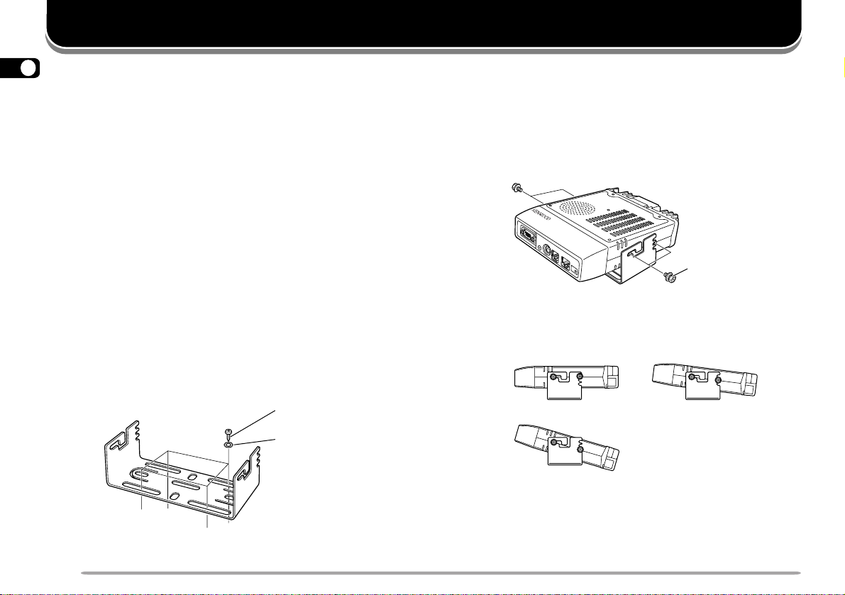
■ Main Unit Installation
1 Install the mounting bracket in the vehicle using
the supplied self-tapping screws and flat washers.
There are 4 screws and 4 washers supplied.
• The bracket must be installed so that the 3 screw
holes on the edge of each bracket side are facing
backward.
Self-tapping screw
(5 mm x 16 mm)
Flat washer
2 Position the transceiver, then insert and tighten
the supplied hexagon SEMS screws and flat
washers. There are 2 screws and 2 washers
supplied for each side of the bracket.
• Double check that all hardware is tightened to
prevent vehicle vibration from loosening the bracket
or transceiver.
SEMS screw
• Determine the appropriate angle of the main unit,
using the 3 screw holes on the rear edge of each
bracket side.
2
Page 9
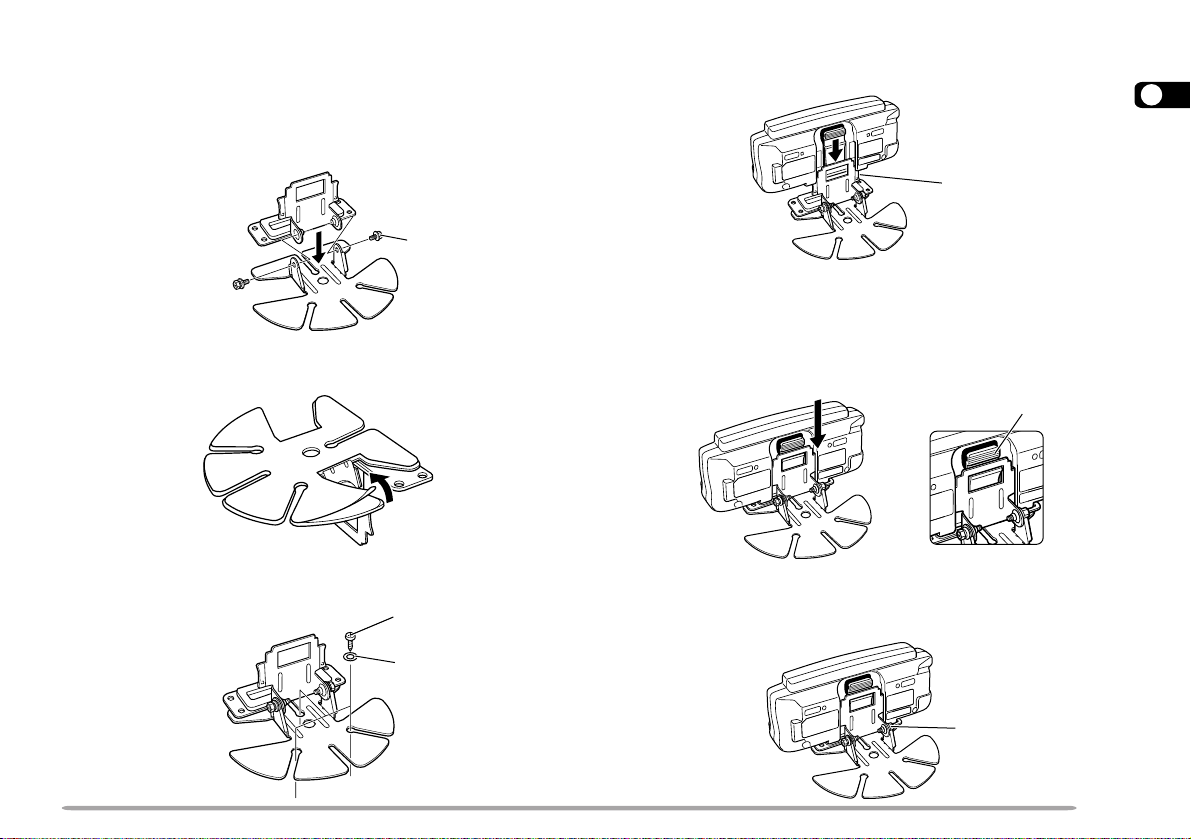
■ Front Panel Installation
1 Assemble the mounting brackets using the
supplied 2 hexagon SEMS screws and 2 flat
washers.
• Do not completely tighten the screws in this step.
SEMS screw
2 Peel off the paper backing from the rear of the
bracket.
3 Position the bracket in the vehicle, then install it
securely using the supplied 3 self-tapping screws
and 3 flat washers.
Self-tapping screw
(4 mm x 14 mm)
Flat washer
4 Position the grooves on the front panel over the
bracket tabs.
1
Bracket tab
5 Slide the front panel down until its locking tab
clicks.
• The tab on the front panel must be completely locked
by the bracket; otherwise vehicle vibration may
cause the front panel to drop off the bracket.
Locking tab
6 Determine the angle of the front panel, then
completely tighten the 2 SEMS screws on the
bracket.
SEMS screw
3
Page 10
FIXED STATION INSTALLATION
MODULAR PLUG CABLE CONNECTION
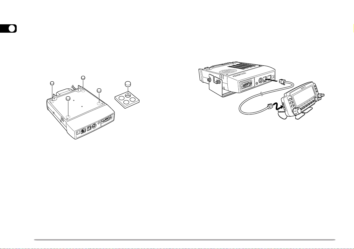
When placing the main unit on such a surface as a desk
1
top, use the supplied cushions to prevent the surface
from being scratched. Attach the 4 pieces of cushions to
the specified positions on the rear of the main unit.
Note: Attach all the cushions to the flat surface on the main unit;
otherwise the installation will be unstable or the cushions may come off
easily.
Use the supplied modular plug cable to connect the front
panel to the main unit. Connect the 4-pin plug to the
front panel and 6-pin plug to the main unit.
Note: The 6-pin plug is wider than the 4-pin plug.
6-pin plug
4-pin plug
4
Page 11

DC POWER CABLE CONNECTION
■ Mobile Operation
The vehicle battery must have a nominal rating of 12 V.
Never connect the transceiver to a 24 V battery. Be
sure to use a 12 V vehicle battery that has sufficient
current capacity. If the current to the transceiver is
insufficient, the display may darken during transmission,
or transmit output power may drop excessively.
1 Route the DC power cable supplied with the
transceiver directly to the vehicle’s battery
terminals using the shortest path from the
transceiver.
• If using a noise filter, it should be installed with an
insulator to prevent it from touching metal on the
vehicle.
• It is recommended not to use the cigarette lighter
socket since some cigarette lighter sockets introduce
an unacceptable voltage drop.
• If the power cable must be routed through a hole in
the vehicle chassis or body, for example in the
firewall at the front of the passenger compartment,
use a rubber grommet to protect the cable from
abrasion. Dismantle the fuse holder to pass the
cable through the firewall.
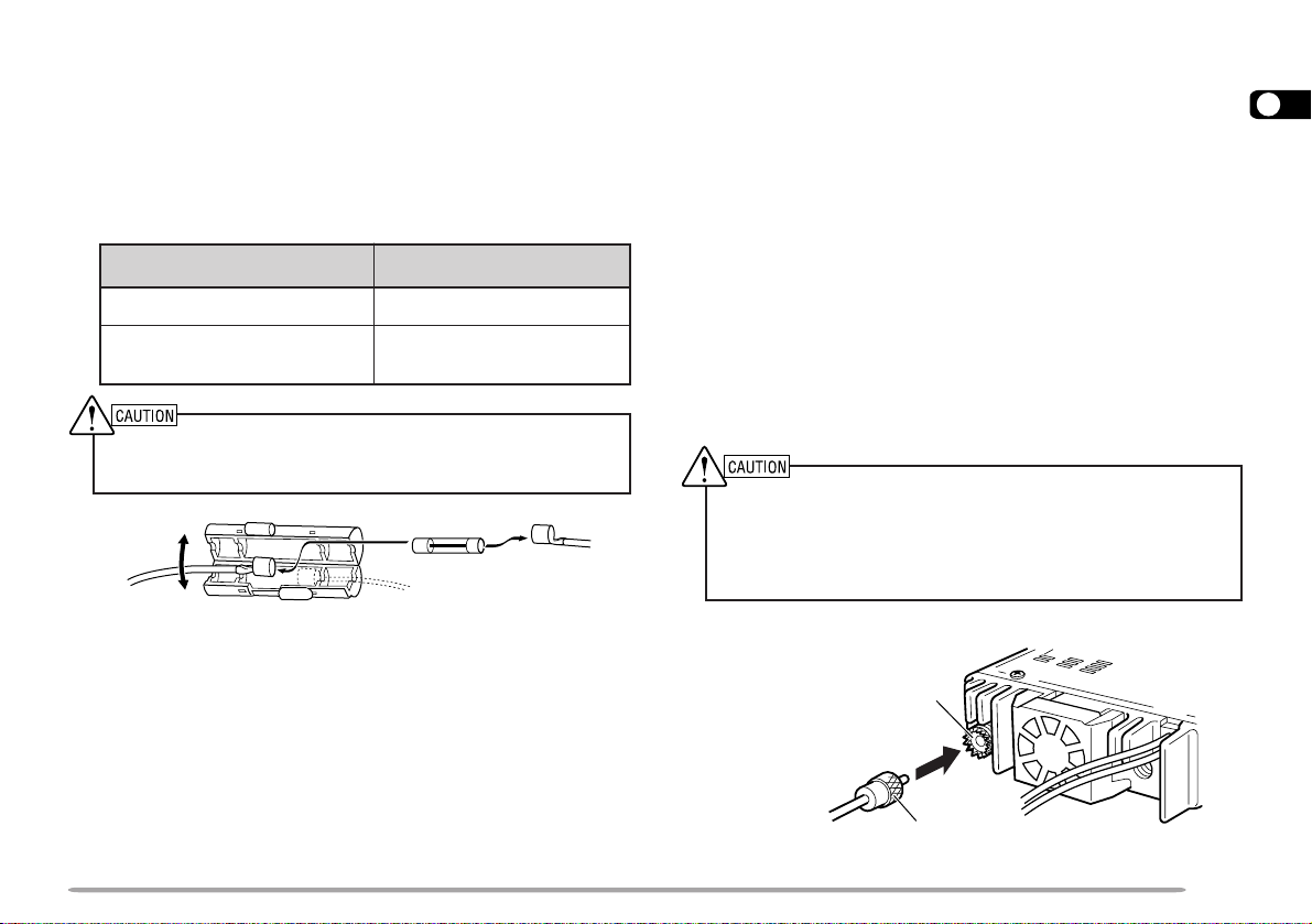
2 After the cable is in place, wind heat-resistant tape
around the fuse holder to protect it from moisture.
Tie down the full run of cable.
3 To prevent the risk of short circuits, disconnect
other wiring from the negative (–) battery terminal
before connecting the transceiver.
4 Confirm the correct polarity of the connections,
and attach the power cable to the battery
terminals; red connects to the positive (+)
terminal, black connects to the negative (–)
terminal.
• Use the full length of the cable without cutting off
excess even if the cable is longer than required. In
particular, never remove the fuse holders from the
cable.
Red
Fuse holder
Black
5 Reconnect any wiring removed from the negative
terminal.
6 Connect the DC power cable to the transceiver’s
power supply connector.
• Press the connectors firmly together until the locking
tab clicks.
1
• The entire length of the cable must be dressed so it
is isolated from heat, moisture, and the engine
secondary (high voltage) ignition system/ cables.
Fuse holder
5
Page 12
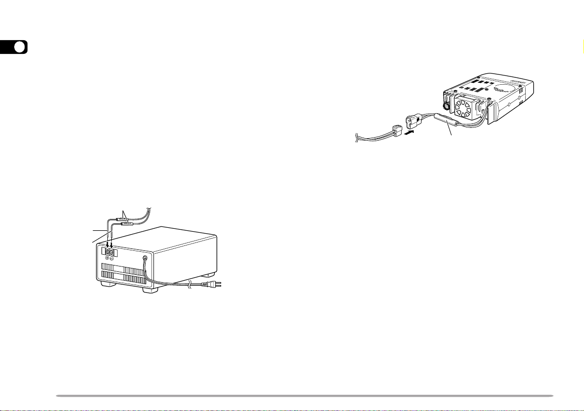
■ Fixed Station Operation
In order to use this transceiver for fixed station
1
operation, you will need a separate 13.8 V DC power
supply that must be purchased separately. The
recommended current capacity of your power supply
is 12 A.
1 Connect the DC power cable to the regulated DC
power supply and check that polarities are correct
(Red: positive, Black: negative).
• DO NOT directly connect the transceiver to an AC
outlet.
• Use the supplied DC power cable to connect the
transceiver to a regulated power supply.
• Do not substitute a cable with smaller gauge wires.
Fuse holder
Red (+)
Black (–)
Regulated DC power
supply
T o AC outlet
2 Connect the transceiver’s DC power connector to
the connector on the DC power cable.
• Press the connectors firmly together until the locking
tab clicks.
Fuse holder
Note:
◆
For your transceiver to fully exhibit its performance capabilities,
the following optional power supply is recommended:
PS-33 (20.5 A, 25% duty cycle).
◆
Before connecting the DC power supply to the transceiver, be
sure to switch the transceiver and the DC power supply OFF.
◆
Do not plug the DC power supply into an AC outlet until you
make all connections.
6
Page 13
■ Replacing Fuses
If the fuse blows, determine the cause, then correct
the problem. After the problem is resolved, replace
the fuse. If newly installed fuses continue to blow,
disconnect the power cable and contact your
authorized KENWOOD dealer or an authorized
KENWOOD service center for assistance.
noitacoLesuF gnitaRtnerruCesuF
reviecsnarTA51
yrosseccAdeilppuS
elbaCrewoPCD
Only use fuses of the specified type and rating; otherwise the
transceiver could be damaged.
Note: If you use the transceiver for a long period when the vehicle
battery is not fully charged, or when the engine is OFF, the battery
may become discharged, and will not have sufficient reserves to start
the vehicle. Avoid using the transceiver under these conditions.
A02
ANTENNA CONNECTION
Before operating, you must first install an efficient,
well-tuned antenna. The success of your installation will
depend largely on the type of antenna and its correct
installation. The transceiver can give excellent results if
the antenna system and its installation are given careful
attention.
You should choose a 50 Ω impedance antenna to match
the transceiver input impedance. Use low-loss coaxial
feed line that also has a characteristic impedance of
50 Ω. Coupling the antenna to the transceiver via feed
lines having an impedance other than 50 Ω reduces the
efficiency of the antenna system, and can cause
interference to nearby broadcast television receivers,
radio receivers, and other electronic equipment.
◆
Transmitting without first connecting an antenna or other
matched load may damage the transceiver. Always connect the
antenna to the transceiver before transmitting.
◆
All fixed stations should be equipped with a lightning arrester to
reduce the risk of fire, electric shock, and transceiver damage.
Antenna
connector
1
To antenna
Feed line connector
7
Page 14
ACCESSORY CONNECTIONS
1
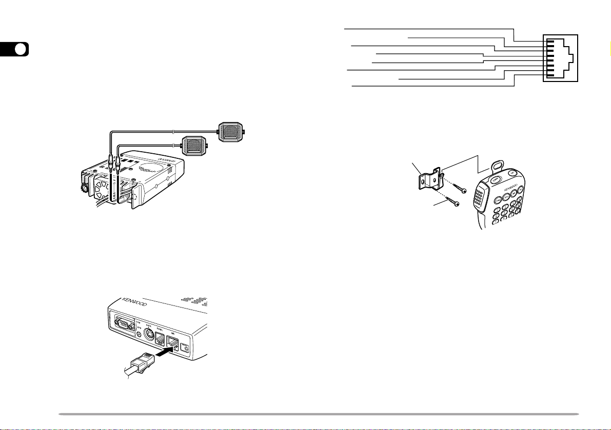
■ External Speakers
If you plan to use external speakers, choose
speakers with an impedance of 8 Ω . The external
speaker jacks accept a 3.5 mm (1/8") mono (2conductor) plug. Recommended speakers include
the SP-50B.
■ Microphone
To communicate in the voice modes, connect a 600 Ω
microphone equipped with an 8-pin modular plug into
the modular socket on the front of the main unit.
Press firmly on the plug until the locking tab clicks.
UP
DC 8 V, 200 mA max.
GND
STBY (PTT)
GND (MIC)
MIC
NC: No connection
DWN
For the U.S.A./ Canada version, a microphone hanger is
supplied. Attach the hanger to an appropriate position
using the screws included in the screw set.
Microphone
hanger
Microphone
hanger screw
(3 mm x 10 mm)
8
Page 15
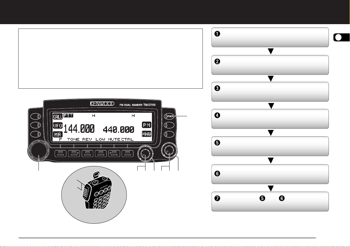
YOUR FIRST QSO
YOUR FIRST QSO
If you tend to discard instruction manuals along with the
packaging material .....please don’t. The 7 steps given here will
get you on the air in your first QSO right away. So, you can enjoy
the exhilaration that comes with opening a brand new
transceiver.
After trying the rig for a while, settle back in your most
comfortable operating chair with this manual and your favorite
drink for an hour or two. The time spent will be worthwhile.
q
r
t
y
MC-53DM
w we w we
Switch ON the DC power supply, then
press the PWR switch.
Turn the VOL and SQL controls to
approximately 9 o’clock.
Press [BAND SEL] to select the VHF
or UHF band.
Turn the Tuning control to select a
frequency.
Press and hold Mic [PTT], then speak
in a normal tone of voice.
Release Mic [PTT] to receive.
Repeat steps and to continue
communication.
2
9
Page 16
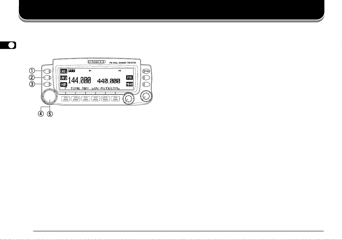
GETTING ACQUAINTED
FRONT PANEL
Note: This section describes only the main functions of the front panel
3
controls and buttons. For the functions not described here, you will find
explanations in the appropriate sections of the manual.
qq
q CALL button
qq
Recalls the Call channel {page 39}. Also starts or
stops Call/VFO Scan {page 54} when in VFO mode,
or Call/Memory Scan {page 54} when in Memory
Recall mode.
ww
w VFO button
ww
Selects the VFO mode. In this mode you can change
the operating frequency, using the Tuning control or
Mic [UP]/ [DWN]. Also provides:
• VFO Scan start to scan the entire VFO range
{page 50}.
• Program Scan start to scan a programmed range of
frequencies {page 52}.
ee
e MR button
ee
Selects the Memory Recall mode {page 37}. In this
mode you can change memory channels, using the
Tuning control or Mic [UP]/ [DWN]. Also starts
Memory Scan {page 50}.
rr
r Tuning control
rr
When turned, selects:
• Operating frequencies when in VFO mode {page 20}.
• Memory channels when in Memory Recall mode
{page 37}.
• Menu Nos. when in Menu mode {page 22}.
This control is used for various other selections.
When an up-arrow (c) and down-arrow (d) are
visible as button labels, the Tuning control functions
in exactly the same way as the up- and down-arrow
keys.
tt
t MHz button
tt
When pressed, selects the MHz mode. In this mode
you can change the operating frequency in 1 MHz
steps or 10 MHz steps {page 20}, using the Tuning
control or Mic [UP]/ [DWN]. Also starts MHz Scan
{page 53}.
10
Page 17
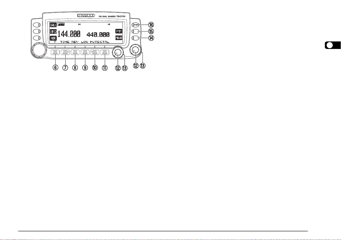
yy
y F (Function) button
yy
Allows you to select the different functions that are
available using the multifunction buttons.
uu
u TONE button
uu
Activates the Tone {page 30}, CTCSS {page 55}, or
DCS function {page 57}.
ii
i REV button
ii
Switches the transmit frequency and receive
frequency when operating with an offset {page 29} or
an odd-split memory channel {page 36}.
oo
o LOW button
oo
Selects High, Medium, or Low transmit output power
{page 21}.
!0!0
!0 MUTE button
!0!0
Mutes the speaker allocated to the control band
{page 72}.
!1!1
!1 CTRL button
!1!1
Selects the band that you can control using the front
panel buttons or the microphone keys {page 17}.
!2!2
!2 VOL controls/ BAND SEL buttons
!2!2
When turned, adjusts the level of receive audio from
the speaker {page 19}. Turn the left control (band A)
or the right control (band B) depending on which
band you want to operate.
When pressed, these buttons select the desired TX
band. Press the left button (band A) or the right
button (band B) depending on which band you want
to select.
For band A and B, see page 17.
!3!3
!3 SQL control
!3!3
When turned, adjusts the squelch level {page 20}.
This allows you to mute speaker output while no
signals are present.
!4!4
!4 MNU button
!4!4
Selects the Menu mode {page 22}.
!5!5
!5 PM button
!5!5
Selects the Programmable Memory (PM) mode {page
44}.
!6!6
!6 PWR switch
!6!6
Switches the transceiver ON or OFF {page 19}.
3
11
Page 18
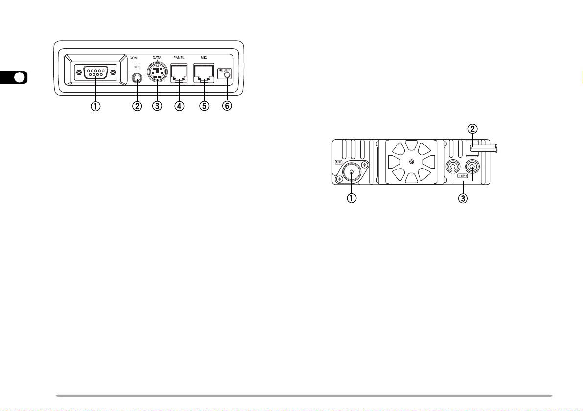
MAIN UNIT- FRONT
3
yy
y RESET button
yy
Press for 1 second or longer to perform Full Reset
{page 41}. No confirmation message appears. Use
this switch when the microcomputer and/or the
memory chip malfunction because of ambient factors.
Note: With the transceiver power ON, do not connect cables to or
remove from the front panel of the main unit.
qq
q COM connector
qq
Accepts a DB-9 female connector for connecting to a
computer. See the separate manual, “SPECIALIZED
COMMUNICATIONS” {page 2}.
ww
w GPS jack
ww
Accepts a 2.5 mm (1/10") 3-conductor plug for
connecting to a GPS receiver. See the separate manual,
“SPECIALIZED COMMUNICATIONS” {page 10}.
ee
e DATA connector
ee
Accepts a 6-pin mini DIN plug for connecting to an
external TNC or an optional VC-H1. See the separate
manual, “SPECIALIZED COMMUNICA TIONS” {pages 2
and 35}.
rr
r PANEL connector
rr
Insert one end of the supplied modular plug cable for
connecting the front panel {page 4}.
tt
t MIC connector
tt
Insert the modular plug on the microphone cable until
the locking tab clicks {page 8}.
12
MAIN UNIT- REAR
qq
q Antenna connector
qq
Connect an external antenna {page 7}. When making
test transmissions, connect a dummy load in place of
the antenna. The antenna system or load should
have an impedance of 50 Ω . The TM-D700E accepts
a male N-type connector and other versions accept a
male PL-259 connector. This transceiver has only
one antenna connector because of a built-in duplexer.
ww
w Power Input 13.8 V DC cable
ww
Connect a 13.8 V DC power source. Use the
supplied DC power cable {pages 5 and 6}.
ee
e Speaker jacks
ee
If you wish, connect an optional external speaker for
clearer audio. These jacks accept a 3.5 mm (1/8")
mono (2-conductor) plug. See page 8.
Page 19
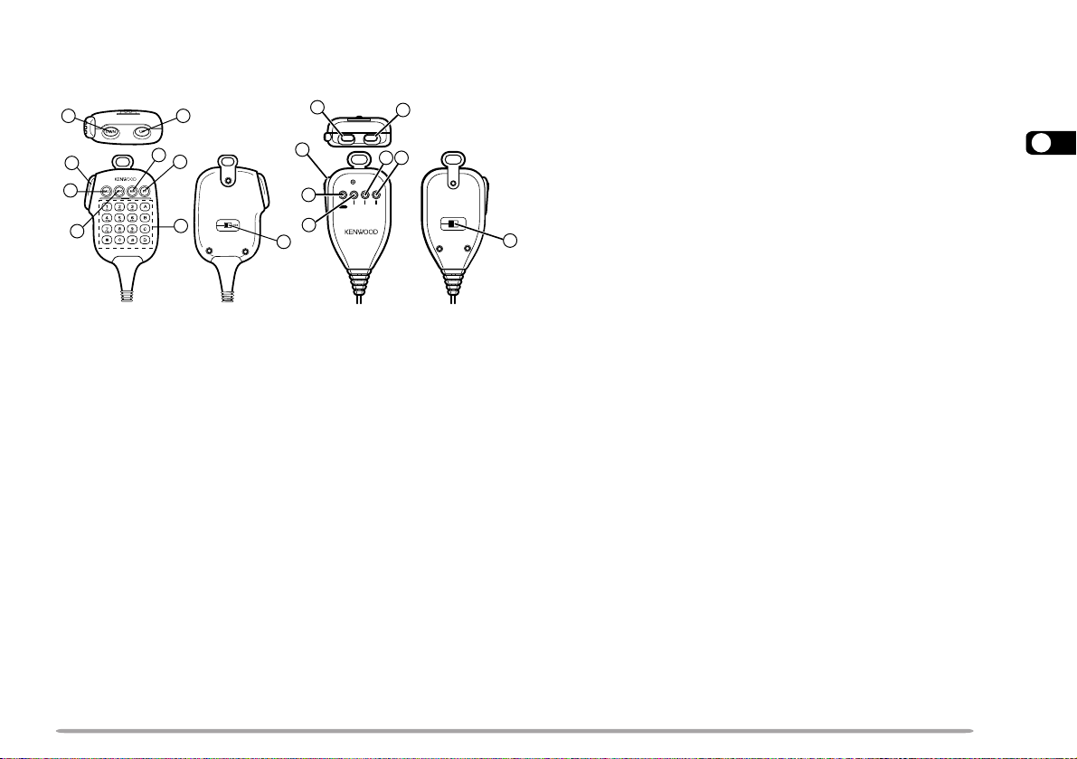
MICROPHONE
MC-53DM MC-45
3
5
6
7
tt
t CALL key
tt
yy
y VFO key
yy
uu
u MR key
12
8
6
2
DWN UP
3
5
6
4
1
7
8
MIC
VFO MR PFCALL
LOCK
ELECTRET CONDENSER MIC
MADE IN JAPAN
uu
Identical to the front panel CALL, VFO and MR
buttons. These keys can be reprogrammed, if
3
desired {page 62}.
ii
i PF key
ii
4
Depending on which function you select in Menu 1–8–1
(PF1), the function of this key differs. Refer to
“PROGRAMMABLE FUNCTION (PF) KEYS” {page 62}.
oo
o DTMF keypad (MC-53DM only)
oo
qq
q UP button
qq
ww
w DWN button
ww
Raises or lowers the operating frequency, the
memory channel number, the menu number, etc.
Holding either button down causes the action to be
repeated. Also, switches between values for
functions with multiple choices.
ee
e PTT (Push-to-Talk) switch
ee
Press and hold to transmit, then release to receive.
rr
r LOCK switch
rr
Locks all microphone keys except [PTT] and (if
equipped) the DTMF keypad.
The 16-key keypad is used for DTMF functions
{page 59}, or to directly enter an operating frequency
{page 63}, a memory channel number {page 37}, a
tone frequency {page 30}, or a CTCSS frequency
{page 56}. The keypad is also available to program a
memory channel name {pages 38 and 60}, Power-ON
message {page 71}, or other character strings.
13
Page 20
rotacidnI
uoYtahW
detceleS
otsserPuoYtahW
lecnaC
.feR
egaP
tuo-dekcoL
yromem
lennahc
.3–4–1uneMesU15
dnaBotuA
egnahC
]F[ , ].C.B.A[ 66
reviecsnarT
kcoL
]F[ , ]zHM[ 76
kcoLlortnoc-llA
REWOP+]zHM[
NO neht, ]F[ , ]zHM[
76
etuMrekaepS ]ETUM[ 27
edomtekcaP )s1(]F[ , ]CNT[ )4(
edomSRPA
)s1(]F[ , ]CNT[ ,
)s1(]F[ , ]CNT[
)11(
timsnartworraN
noitaived
1
.6–3–1uneMesU27
INDICATORS
On the display you will see various indicators that show
what you have selected.
3
1
TM-D700E only
14
rotacidnI
uoYtahW
detceleS
noitcnufenoT
]ENOT[ , ]ENOT[ ,
]ENOT[
otsserPuoYtahW
lecnaC
.feR
egaP
03
SSCTC ]ENOT[ , ]ENOT[ 55
SCD ]ENOT[ 75
]F[ , ]TFIHS[ , ]F[ ,
tesffosulP
noitcerid
tesffosuniM
noitcerid
tesffosuniM
noitcerid
1
)zHM6.7–(
esreveR ]VER[ 33
citamotuA
kcehCxelpmiS
timsnarthgiH
rewop
muideM
rewop
rewoptimsnart
timsnartwoL
]TFIHS[
eno:E007D-MT(
erom ]F[ , ]TFIHS[ )
]F[ , ]TFIHS[
]F[ , ]TFIHS[ 92
erom ]F[ , ]TFIHS[ )
eno:E007D-MT(
]VER[ 33
tluafeD12
]WOL[ , ]WOL[ ot
tluafedehttceles
]WOL[ tcelesot
tluafedeht
92
92
1
TM-D700E only
For the shaded indicators, see the separate manual,
“SPECIALIZED COMMUNICATIONS”.
When you receive a signal:
12
12
• “BUSY” appears when the squelch {page 20} is open.
• The S-meter shows the strength of received signals.
Page 21
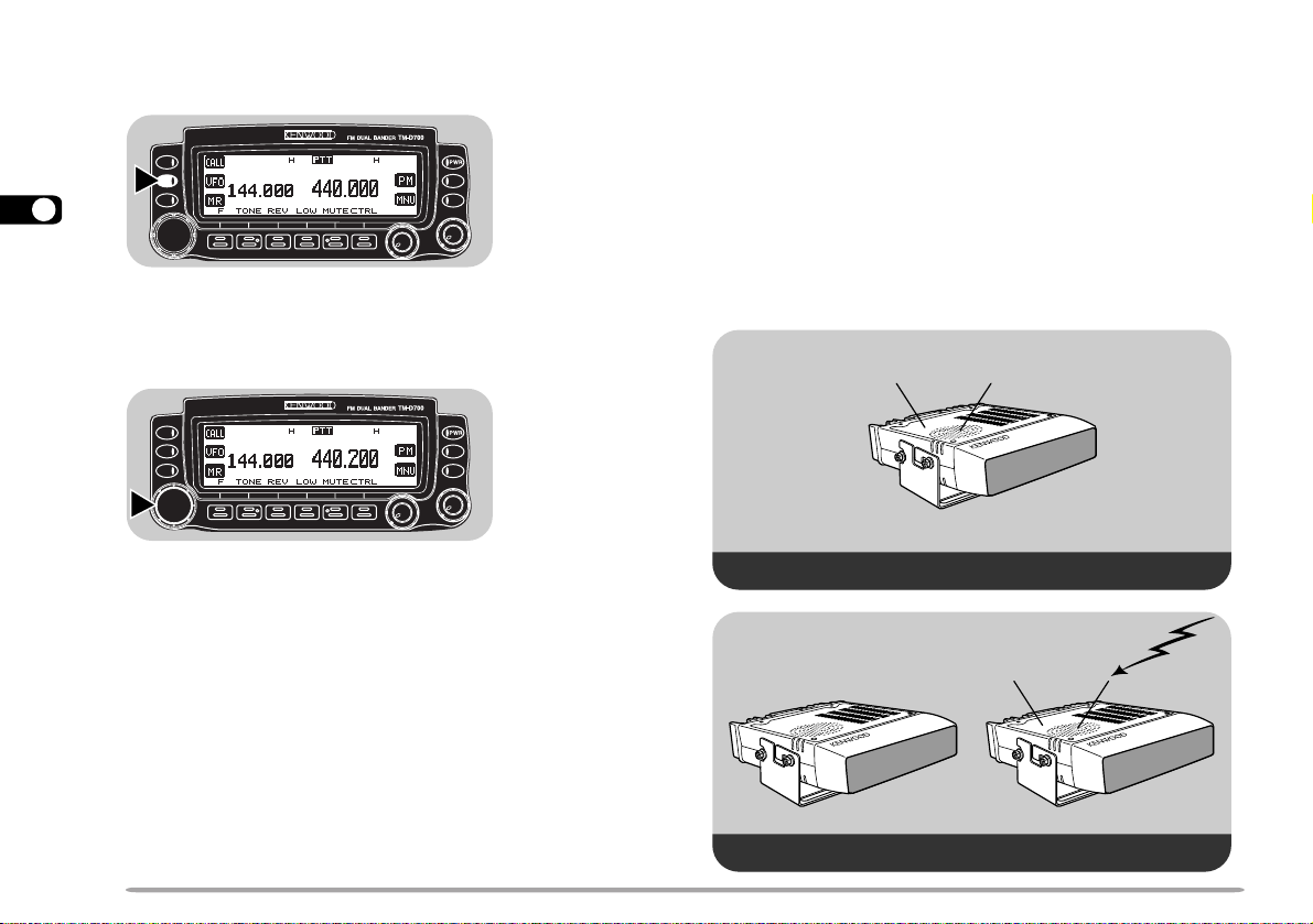
BASIC TRANSCEIVER MODES
1
2
1
2
This section introduces you to the basic modes you can
select.
VFO mode
Press [VFO] to select. You can change the operating
frequency using the Tuning control or Mic [UP]/ [DWN].
Memory Recall mode
Press [MR] to select. You can change memory
channels, using the Tuning control or Mic [UP]/ [DWN],
where you stored frequencies and related data. Refer to
“MEMORY CHANNELS” {page 35}.
Programmable Memory (PM) mode
Press [PM] to select. You can select the transceiver
environment, by pressing [1] to [5], that you stored in
PM channels. Refer to “PROGRAMMABLE MEMORY
(PM)” {page 42}.
Menu mode
Press [MNU] to select. You can change Menu Nos.
cc
using the Tuning control or [
dd
c]/ [
d]. Refer to “MENU
cc
dd
SET-UP” {page 22}.
APRS mode/ Packet mode
Press [F] (1 s), [TNC] to select APRS mode. Press [F] (1 s),
[TNC] again to select Packet mode. In APRS mode, you
can receive and transmit APRS packets. In Packet mode,
you can send commands to the built-in TNC from a personal
computer . Refer to the separate manual, “SPECIALIZED
COMMUNICATIONS” {pages 4 and 11}.
APRS mode
Packet mode
15
3
Page 22
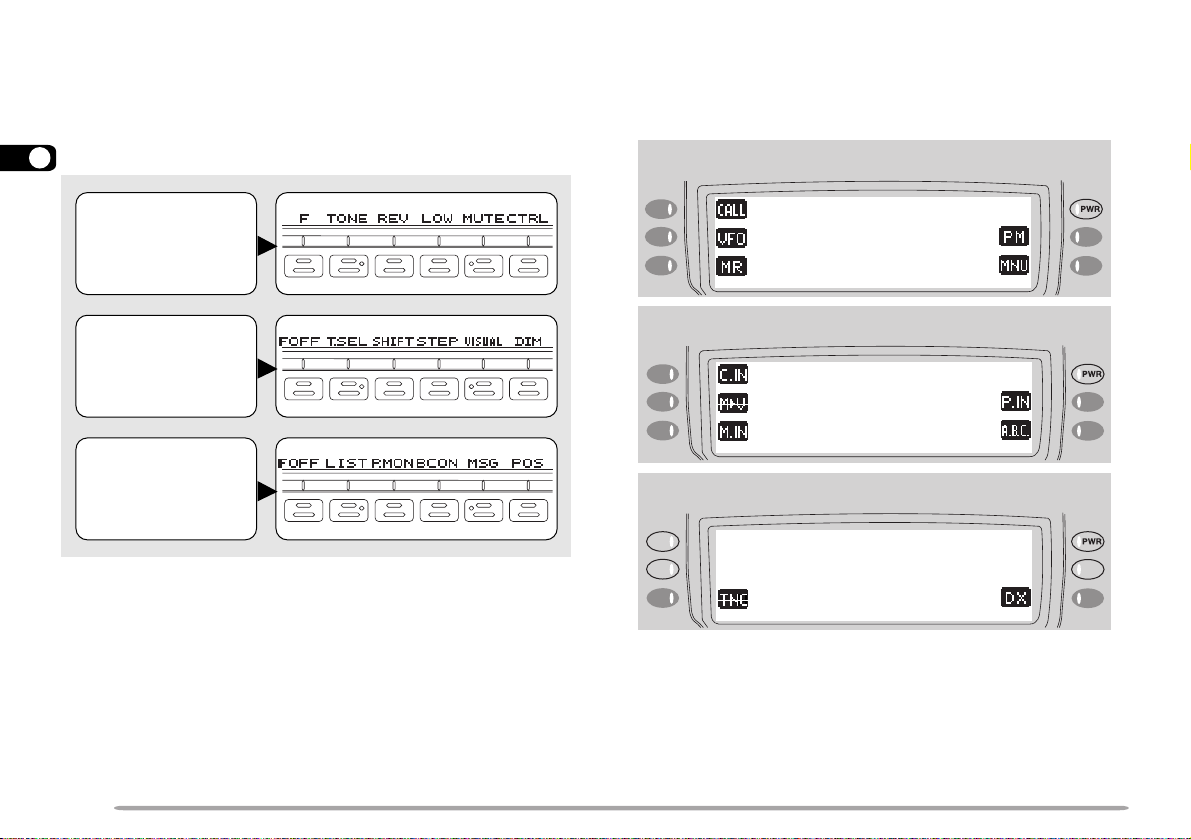
BUTTON FUNCTION DISPLA Y
The functions of the 6 buttons below the display can be
identified through the labels shown at the bottom of the
display. After pressing [F] or [F] (1 s), pressing [F]
([OFF]) again restores the basic state.
3
Basic State
Display Labels
Labels after
Pressing [F]
The labels of the 5 buttons beside the display are shown
at the left end or right end of the display. These labels
will change depending on the current mode.
Basic State Display Labels
Labels after Pressing [F]
Labels after
Pressing [F] (1 s)
Note:
◆
When selecting Programmable Memory (PM) mode, you will see
different labels. See “Programmable Memory (PM) mode” {page 15}.
◆
You can also select different combinations of buttons labels. See
“CHANGING MULTI-FUNCTION BUTT ON LABELS” {page 67}.
16
Labels after Pressing [F] (1 s)
Page 23
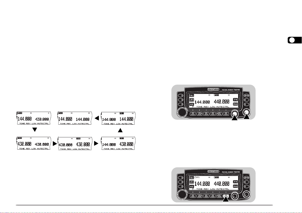
BAND A & B
In this manual, the band recalled at the left on the
display is referred to as band A, and the band at the right
is called band B. In band A you can recall a 144 MHz
band (default) or a 440 (or 430) MHz sub-band. In band
B you can recall a 440 (or 430) MHz band (default) or a
144 MHz sub-band. On the U.S.A./ Canada version, you
can also recall a 118 MHz, 220 MHz, or 300 MHz subband in band A, and a 300 MHz or 1.2 GHz sub-band in
band B. This transceiver is capable of simultaneously
receiving on bands A and B.
Press the left or right [BAND SEL] to select band A or B.
To recall the sub-band, press [F], then the same [BAND
SEL]. The following diagram shows how the bands are
switched on a TM-D700E.
Left
[BAND SEL]
TX BAND AND CONTROL BAND
What confuses you on this radio first could be the ideas
of the TX band and Control band. To avoid confusion,
please note the differences between the TX band and
the Control band.
TX Band
Press the left [BAND SEL] (band A) or the right [BAND
SEL] (band B) to select. “PTT” on the display shows
which band (A or B) is currently selected as the transmit
(TX) band. You can use the TX band to transmit signals
or to control the transceiver.
3
[F], left
[BAND SEL]
Right
[BAND SEL]
Note:
◆
You cannot recall a sub-band in Memory Recall mode. First press
[VFO] to select VFO mode.
◆
You cannot recall the UHF sub-band in band A and the VHF subband in band B at the same time.
◆
The 118 MHz, 220 MHz, 300 MHz, or 1.2 GHz sub-band cannot be
used for transmitting.
◆
For the range of each band, see “SPECIFICATIONS” {page 90}.
[F], right
[BAND SEL]
[F], right
[BAND SEL]
Control Band
Press [CTRL] to select. On the display “Ctrl” appears to
show which band (A or B) is currently selected as the
Control band. Use this function when you want to
control the band which is not currently set as the TX
band. After selecting the Control band, you cannot
control the TX band.
17
Page 24
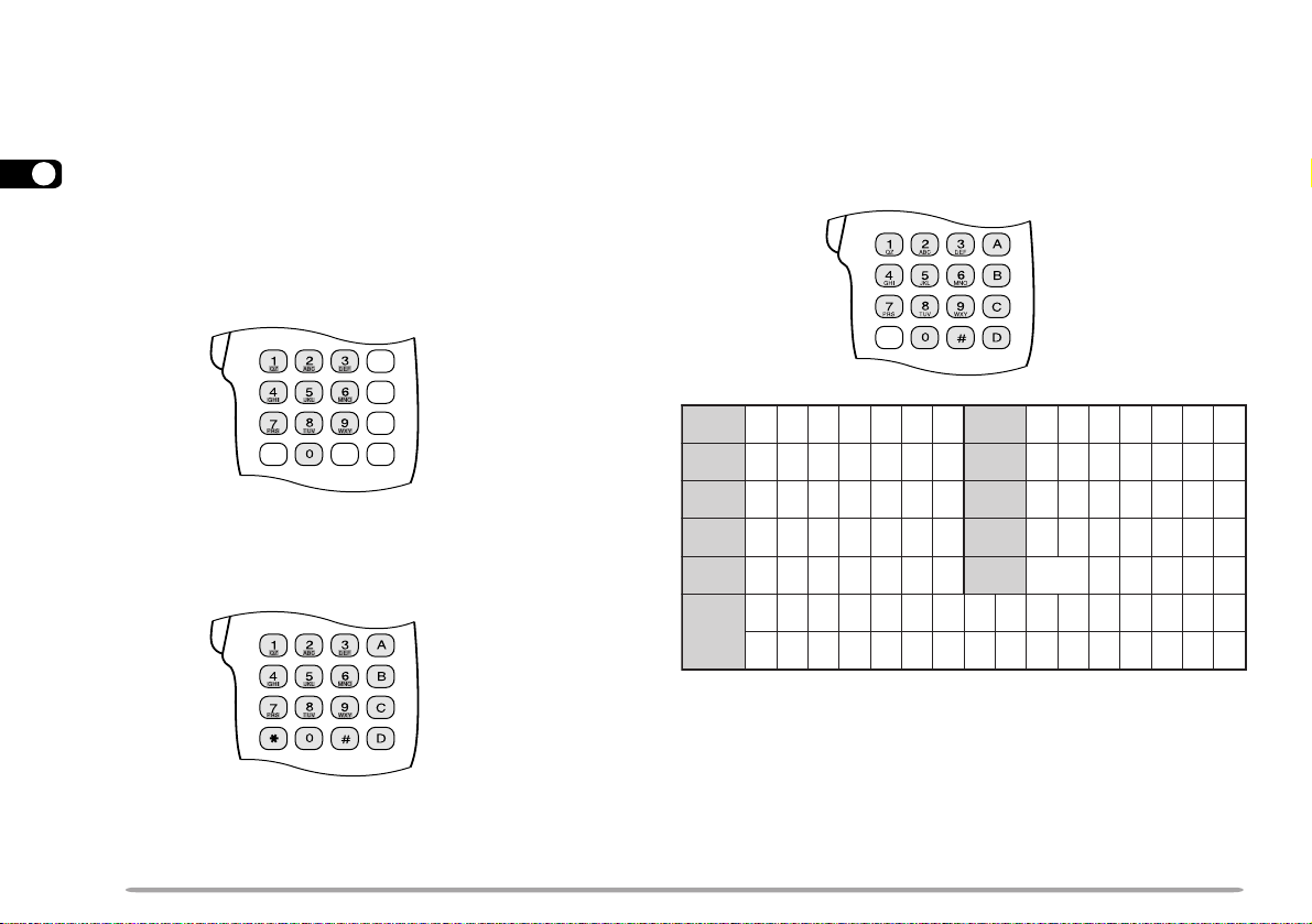
MIC KEYPAD DIRECT ENTRY (MC-53DM ONLY)
1 qz1QZ 6 mno6MNO
2 abc2ABC 7 p r s 7PRS
3 def3DEF 8 tuv8TUV
4 ghi4GHI 9wxy9WXY
5 jkl5JKL 0
ecapS
0
#
?!' .,–/&#%()<>;:
"@
The keypad on the MC-53DM allows you to make
various entries depending on which mode the
transceiver is in.
3
In VFO or Memory Recall mode, use the Mic keypad to
select a frequency {page 63} or memory channel number
{page 37}. In Tone or CTCSS freq. Select mode, use the
keypad to select a Tone frequency {page 30} or CTCSS
frequency {page 56}. First press the Mic PF key
programmed as the ENTER key {page 62}.
To manually send a DTMF number, press and hold Mic
[PTT], then press the DTMF keys on the Mic keypad
{page 59} in sequence.
You can also use the Mic keypad to program a memory
channel name {pages 38 and 60}, Power-ON message
{page 71}, or other character strings. Each press of a
Mic key switches entry of characters as below. You can
always use Mic [A] as [
and [D] as [OK].
aa
a], [B] as [
aa
bb
b], [C] as [DEL],
bb
18
When programming call signs for the Sky Command 2
{page 79}, pressing Mic [0] selects only “0” and pressing
Mic [#] selects only “–”.
Page 25
OPERATING BASICS
SWITCHING POWER ON/OFF
1 Switch ON the DC power supply.
• If operating mobile, skip this step.
2 Press the PWR switch to switch ON the transceiver.
3 To switch OFF the transceiver, press the PWR switch
again.
4 If operating as a fixed station, switch OFF the DC
power supply.
• You may skip step 3. After switching ON the transceiver,
you can switch it OFF or ON using only the power switch
on the DC power supply.
ADJUSTING VOLUME
Turn the VOL control clockwise to increase the audio
level and counterclockwise to decrease the audio level.
4
• If background noise is inaudible because of the Squelch
function, press the Mic PF key assigned the Monitor
function {page 62}, then adjust the VOL control. Press the
PF key again to cancel the Monitor function.
SELECTING A BAND
Press the left [BAND SEL] to select band A, or the right
[BAND SEL] to select band B.
• “PTT” moves to the selected band.
• For band A and B, see page 17.
19
Page 26
SELECTING A FREQUENCY
ADJUSTING SQUELCH
1 Press [VFO] to select VFO mode.
4
2 To increase the frequency, turn the Tuning control
clockwise or press Mic [UP].
To decrease the frequency, turn the Tuning control
counterclockwise or press Mic [DWN].
The current squelch level is incorrect.
• Pressing and holding Mic [UP]/ [DWN] causes the
frequency to step repeatedly.
• To change frequencies in steps of 1 MHz, press [MHz]
(Tuning control) first. Pressing [MHz] again cancels this
function.
• To change frequencies in steps of 10 MHz, press
[F]+[MHz] first. Pressing [F] cancels the 10 MHz
function; pressing [MHz] starts the 1 MHz function.
If using a MC-53DM, you can also use its keypad to
select frequencies. See “DIRECT FREQUENCY ENTRY
(WITH MC-53DM ONLY)” {page 63}.
The current squelch level is correct.
The purpose of the Squelch it to mute the speaker when
no signals are present. With the squelch level correctly
set, you will hear sound only when actually receiving
signals. The higher the squelch level selected, the
stronger the signals must be to receive. The appropriate
squelch level depends on ambient RF noise conditions.
Turn the SQL control when no signals are present.
Select the squelch level at which the background noise
is just eliminated.
Noise
(Squelch opened)
The current squelch level is incorrect.
No speaker output
(Squelch closed)
The current squelch level is correct.
Audio
(Squelch opened)
20
Page 27
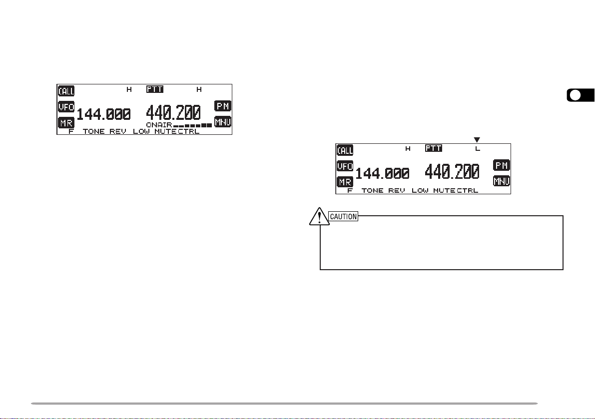
TRANSMITTING
1 To transmit, press and hold Mic [PTT] and speak into
the microphone in a normal tone of voice.
• “ON AIR” and the RF power meter appear.
• Speaking too close to the microphone, or too loudly,
may increase distortion and reduce intelligibility of your
signals at the receiving station.
• The RF power meter shows the relative transmit output
power.
2 When you finish speaking, release Mic [PTT].
Time-Out Timer: Holding down Mic [PTT] for more than 10 minutes
causes the transceiver to generate a beep and stop transmitting.
Release, then press Mic [PTT] to resume transmitting. You may change
the time-out time to 3 or 5 minutes {page 70}.
■ Selecting Output Power
It’s wise to select lower transmit power if communication
is still reliable. This lowers the risk of interfering with
others on the band. When operating from battery
power, you will enjoy more operating time before a
charge is necessary.
Press [LOW] to select high (“H”), medium (“M”), or
low (“L”) power. The default is high.
• You can program a different power for band A and B.
◆
Do not transmit at high output power for an extended period of
time. The transceiver could overheat and malfunction.
◆
Continuous transmission causes the heat sink to overheat.
Never touch the heat sink when it may be hot.
Note: When the transceiver overheats because of ambient high
temperature or continuous transmission, the protective circuit may
function to lower transmit output power.
4
21
Page 28
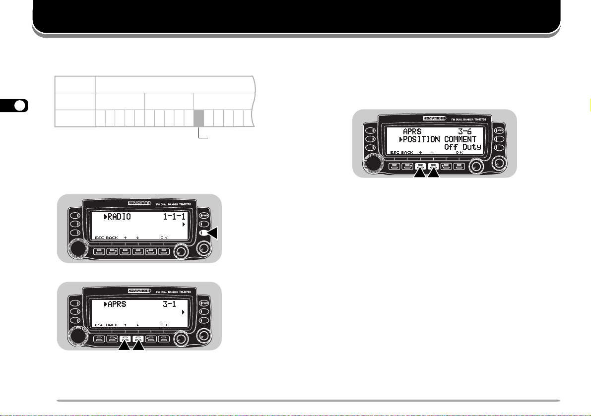
MENU SET-UP
The Menu system on this transceiver consists of 3
levels.
Level 1 1
5
Level 2
12 3
12345123412345 5 6Level 3
Menu 1–3–1
MENU ACCESS
1 Press [MNU] to enter Menu mode.
• The current level 1 No. blinks.
cc
2 Press [
dd
c]/ [
d] to select the appropriate level 1 No.
cc
dd
3 Press [OK].
• The current level 2 No. blinks.
cc
4 Press [
dd
c]/ [
d] to select the appropriate level 2
cc
dd
No.
• To move back to level 1, press [BACK].
• To exit Menu mode, press [ESC].
5 Press [OK].
6 For Menu 1–1 to 1–9 and 1–A, repeat steps 4 and
5 to select level 3.
cc
7 Press [
• The procedure in this step differs depending on
which menu item you selected. See the appropriate
sections in the manual.
dd
c]/ [
d] to select a parameter.
cc
dd
8 Press [OK] to complete the setting.
9 Press [MNU] to exit Menu mode.
22
Page 29

MENU CONFIGURATION
The shaded Menu Nos. are described in the separate manual, “SPECIALIZED COMMUNICATIONS”.
1leveL 2leveL 3leveL snoitceleS tluafeD
1YALPSID
2OIDUA
1OIDAR
3XR/XT
1
Only with an optional VS-3 unit installed
2
TM-D700E only
1egasseMNO-rewoP.egapecnerefereeS!!OLLEH17
2tsartnoC).xam(61~).nim(1leveL8leveL56
3edomesreveRevitageN/evitisoPevitisoP56
4egnahCremmiDotuAFFO/NO
FFO
5nottubnoitcnuf-itluM3/2/1edoM1edoM76
1emulovpeeB
FFO
/).xam(7~).nim(1leveL
5leveL96
2peeByeKFFO/NONO96
3noitarugifnocrekaepS2/1edoM1edoM27
4rezisehtnySecioV
5emulovecioV
1
1
/ylnoSRPA/hsilgnE
FFO/esenapaJ
FFO38
).xam(7~).nim(1leveL5leveL38
1OFVelbammargorP.egapecnerefereeS—46
2hcleuqSretem-SFFO/NOFFO86
3
emitgnahhcleuqS
4edomMA/MFMA/MF
FFO/.cesm005/052/521FFO86
ecnerefereeS
.egap
5tnioPtpecretnIdecnavdAFFO/NOFFO96
6noitaivedXR/XT
2
worraN/ediWediW27
.feR
egap
5
56
96
23
Page 30

1leveL 2leveL 3leveL snoitceleS tluafeD egap.feR
1erotSlennahCMPotuAFFO/NONO54
5
1OIDAR
1
U.S.A./ Canada only
4YROMEM
5FMTD
6 CNT
7
2yalpsiDlennahCFFO/NOFFO04
3tuokcoLlennahCyromeMFFO/NOFFO15
4emanlennahcyromeM.egapecnerefereeS—83
1erotSrebmuN.egapecnerefereeS—06
2deepsXTwolS/tsaFtsaF16
3esuaP
.cesm0002/0051
/0001/057/005/052/001
1 dnabataD .egapecnerefereeS AdnaB )5(
2 esnesDCD
dnab
)XR(ataD/sdnabB&A
dnab
3 emiT .egapecnerefereeS — )21(
4 etaD .egapecnerefereeS — )21(
5 enozemiT .egapecnerefereeS — )31(
1ycneuqerftesffO
zHk05fo
spetsnizHM59.92~00.0
.egap
2tesffOretaepeRcitamotuAFFO/NONO13
3noitcnuFnottuBllaCXTzH0571/llaCllaC23
RETAEPER
4dloHXTFFO/NOFFO23
5dloHretaepeR
6noitcnufretaepeR
1
1
FFO/NOFFO28
/dnab-ssorC/dnab-dekcoL
FFO
.cesm00516
)XR(ataD
ecnerefereeS
FFO28
)5(
92
24
Page 31

1leveL 2leveL 3leveL snoitceleS tluafeD
1yeKFPciM.egapecnerefereeSB/A26
2yeKRMciM.egapecnerefereeSRM26
.feR
egap
8CIM
3yeKOFVciM.egapecnerefereeSOFV26
4yeKLLACciM.egapecnerefereeSLLAC
5lortnoCenohporciMFFO/NOFFO37
6rotinoMFMTDFFO/NOFFO95
1emuseRnacS
1OIDAR
2
nacSlausiV
3)OPA(ffOrewoPcitamotuAFFO/NOFFO07
9XUA
4)TOT(remiTtuO-emiTsetunim01/5/3setunim0107
5 tropMOC
2
6 tropataD spb0069/0021 spb0021 )5(
7teseR.egapecnerefereeS—14
1edocterceS.egapecnerefereeS00047
ETOMER
A
3
NOC
2tnemegdelwonkcAFFO/NOFFO57
3lortnoCetomeRFFO/NOFFO57
1
TM-D700E: 1750 Hz Tone
2
After changing the selection, switch the transceiver OFF, then ON.
3
U.S.A./ Canada only
1
/detarepO-emiT
keeS/detarepO-reirraC
rofslennahCforebmuN
181/19/16/131674
/00483/00291/0069
spb00675
-emiT
detarepO
spb0069 )4(
26
5
94
25
Page 32

1leveL 2leveL snoitceleS tluafeD
.feR
egap
1 ngisllacyM .egapecnerefereeS — )63(
2 ngisllacrofroloC
/deR/eulB/kcalB/etihW
wolleY/nayC/neerG/atnegaM
etihW )73(
3 egasseM .egapecnerefereeS — )63(
5
2 VTSS
4 egassemrofroloC
5 troperVSR .egapecnerefereeS — )63(
6 troperVSRrofroloC
/deR/eulB/kcalB/etihW
wolleY/nayC/neerG/atnegaM
/deR/eulB/kcalB/etihW
wolleY/nayC/neerG/atnegaM
etihW )73(
etihW )73(
7 etucexEnoitisopmirepuS .egapecnerefereeS — )73(
8 edomVTSS .egapecnerefereeS — )83(
9 lortnoC1H-CV FFO/NO FFO )83(
1 ngisllacyM .egapecnerefereeS — )71(
2 reviecerSPG 69AEMN/AEMN/desutoN desutoN )01(
3 tniopyaW .egapecnerefereeS FFO )51(
4 noitisopyM .egapecnerefereeS — )91(
26
3 SRPA
5 ytiugibmAnoitisoP FFO/stigid4/3/2/1 FFO )62(
6 tnemmocnoitisoP .egapecnerefereeS ytuDffO )02(
7 ecnatsidnoitcirtsernoitpeceR
FFO/01
fospetsni0052~01
FFO )62(
8 nocinoitatS .egapecnerefereeS — )81(
9 txetsutatS .egapecnerefereeS — )12(
Page 33

3 SRPA
1leveL 2leveL snoitceleS tluafeD
A etartimsnarttxetsutatS .egapecnerefereeS FFO )52(
B htaptekcaP .egapecnerefereeS
C dohtemtimsnarttekcaP otuA/TTP/launaM launaM )52(
D lavretnitimsnarttekcaP
setunim03
/02/01/5/3/2/1/5.0/2.0
E edocpuorG .egapecnerefereeS 101KPA )22(
F peeB FFO/llA/wenllA/eniM llA )92,41(
G ecnatsidroftinU retemoliK/eliM retemoliK
H erutarepmetroftinU ° /F °C °C
I dnabataD .egapecnerefereeS AdnaB )31(
J etarrefsnarttekcaP spb0069/0021 spb0021 )31(
K retaepigiD FFO/NO FFO )72(
L htapgnitaepigiD .egapecnerefereeS YALER )72(
M ylpeRrewsnAotuA FFO/NO FFO )33(
N egassemylpeR .egapecnerefereeS — )33(
O puorgnitelluB .egapecnerefereeS — )43(
P puorgegasseM .egapecnerefereeS — )43(
1
EDIW,YALER
setunim3 )52(
1
.feR
egap
)32(
5
)61(
)61(
YKS
4
DMC
2ngisllacretropsnarT.egapecnerefereeS—97
/.A.S.U(
3ycneuqerfenoT.egapecnerefereeSzH5.8897
)adanaC
4edomdnammoCykS
1
U.S.A./ Canada: Mile and °F
1ngisllacrednammoC.egapecnerefereeS—97
FFO/retropsnarT/rednammoC
FFO87
27
Page 34
OPERATING THROUGH REPEATERS
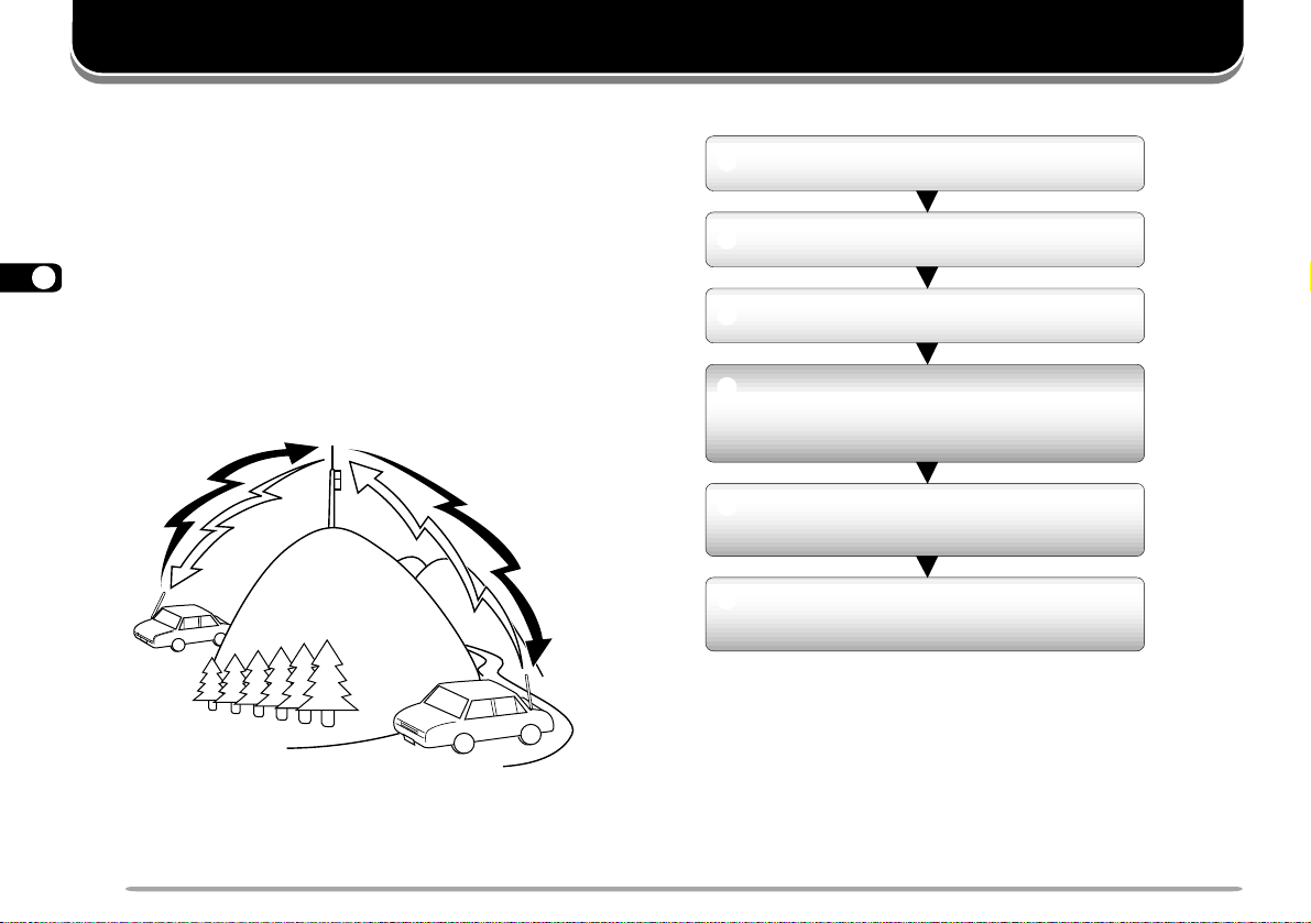
Repeaters, which are often installed and maintained by
radio clubs, are usually located on mountain tops or
other elevated locations. Generally they operate at
higher ERP (Effective Radiated Power) than a typical
station. This combination of elevation and high ERP
allows communications over much greater distances
than communications without using repeaters.
6
Most repeaters use a receive and transmit frequency
pair with a standard or non-standard offset (odd-split). In
addition, some repeaters must receive a tone from the
transceiver to allow it to access. For details, consult
your local repeater reference.
TX: 144.725 MHz
TX tone: 88.5 Hz
RX: 145.325 MHz
TX: 144.725 MHz
TX tone: 88.5 Hz
RX: 145.325 MHz
Offset Programming Flow
q
Select a band.
w
Select a receive frequency.
e
Select an offset direction.
r
Select an offset frequency.
(Only when programming odd-split
repeater frequencies)
t
Activate the Tone function.
(If necessary)
y
Select a tone frequency.
(If necessary)
If you store the above data in a memory channel, you
need not reprogram every time. See “MEMORY
CHANNELS” {page 35}.
28
Page 35

PROGRAMMING OFFSET
First select band A or B by pressing the left or right
[BAND SEL]. To recall the sub-band next, press [F],
then the same [BAND SEL].
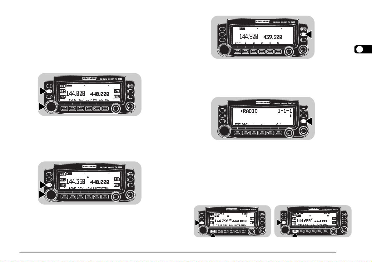
■ Selecting Offset Direction
Select whether the transmit frequency will be higher
(+) or lower (–) than the receive frequency.
Press [F], [SHIFT] to switch the offset direction.
• “+” or “–” appears to indicate which offset direction is
selected.
• To program –7.6 MHz offset on the TM-D700E (UHF
only), repeatedly press [F], [SHIFT] until “=” appears.
If the offset transmit frequency falls outside the
allowable range, transmitting is inhibited. Use one of
the following methods to bring the transmit frequency
within the band limits:
• Move the receive frequency further inside the band.
• Change the offset direction.
Note: While using an odd-split memory channel or transmitting, you
cannot change the offset direction.
■ Selecting Offset Frequency
To access a repeater which requires an odd-split
frequency pair, change the offset frequency from the
default which is used by most repeaters. The default
offset frequency on the VHF band is 600 kHz no
matter which market version; the default on the UHF
band is 5 MHz (TM-D700A) or 1.6 MHz (TM-D700E).
1 Press [MNU] to enter Menu mode.
cc
2 Press [
dd
c]/ [
d] to select “RADIO (1–)”, then press
cc
dd
[OK].
cc
3 Press [
dd
c]/ [
d] to select “REPEATER (1–7–)”,
cc
dd
then press [OK].
cc
4 Press [
dd
c]/ [
d] to select “OFFSET FREQUENCY
cc
dd
(1–7–1)”, then press [OK].
cc
5 Press [
dd
c]/ [
d] to select the appropriate offset
cc
dd
frequency.
• The selectable range is from 0.00 MHz to 29.95 MHz
in steps of 50 kHz.
6 Press [OK] to complete the setting.
7 Press [MNU] to exit Menu mode.
TM-D700E Only: If you have selected “ =” for the offset direction,
you cannot change the default (7.6 MHz).
Note: After changing the offset frequency, the new offset frequency
will also be used by Automatic Repeater Offset.
6
29
Page 36

■ Activating Tone Function
.oN
.qerF
)zH(
.oN
.qerF
)zH(
.oN
.qerF
)zH(
.oN
.qerF
)zH(
100.76114.79125.631138.291
209.17210.001223.141235.302
304.47315.301322.641337.012
400.77412.701424.151431.812
507.97519.011527.651537.522
605.28618.411622.261636.332
704.58718.811729.761738.142
805.88810.321828.371833.052
905.19913.721929.971
018.49028.131032.681
Press [TONE] to activate the Tone function.
• “T” appears when the Tone function is ON.
6
• Each press of [TONE] changes the selection as Tone –>
CTCSS –> DCS –> No selection.
Note:
◆
You cannot use the T one function with the CTCSS or DCS
function.
◆
You need to activate the Tone function only when selecting one
of the 38 standard frequencies. The selection you make here will
not affect transmission of a 1750 Hz tone.
cc
3 Press [
dd
c]/ [
d] to select the appropriate tone
cc
dd
frequency.
4 Press [OK] to complete the setting.
Note: The procedures for transmitting a 1750 Hz tone are described
on page 32.
1 Press [TONE] to activate the Tone function.
2 Press [F], [T.SEL].
• “T” appears when the Tone function is ON.
• The current tone frequency appears and blinks. The
default is 88.5 Hz.
■ Selecting a Tone Frequency
30
If using a MC-53DM, you can also use its keypad to
select a tone frequency. First program one of the Mic
PF keys as the ENTER key {page 62}. In step 2,
press [ENTER], then enter 01 to 38 shown in the
table. To select 79.7 Hz, for example, press
[ENTER], [0], [5].
Page 37
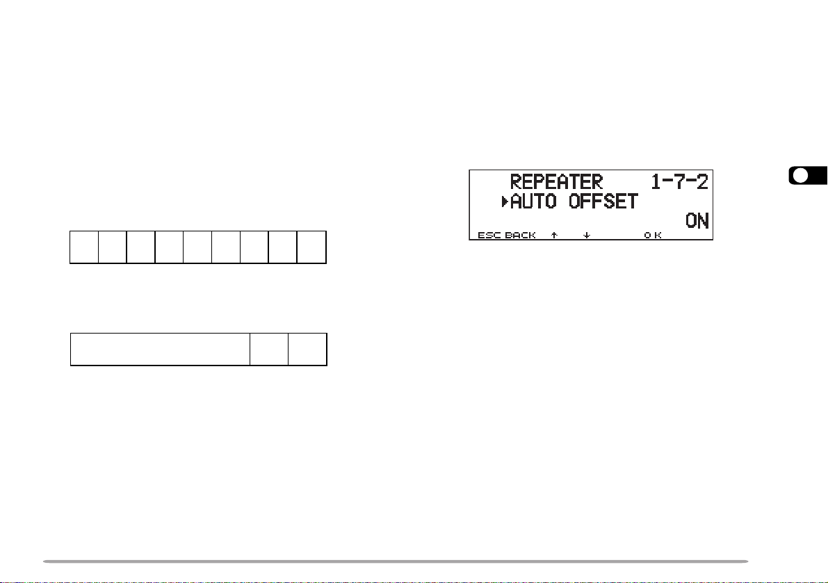
AUTOMATIC REPEATER OFFSET
This function automatically selects an offset direction,
according to the frequency that you select on the VHF
band. The transceiver is programmed for offset direction
as shown below. To obtain an up-to-date band plan for
repeater offset direction, contact your national Amateur
Radio association.
U.S.A. and Canada versions
This complies with the standard ARRL band plan.
144.0 145.5 146.4 147.0 147.6
145.1 146.0 146.6 147.4 148.0 MHz
1 Press [MNU] to enter Menu mode.
cc
2 Press [
dd
c]/ [
d] to select “RADIO (1–)”, then press
cc
dd
[OK].
cc
3 Press [
dd
c]/ [
d] to select “REPEATER (1–7–)”, then
cc
dd
press [OK].
cc
4 Press [
dd
c]/ [
d] to select “AUTO OFFSET (1–7–2)”,
cc
dd
then press [OK].
6
−−
+
SS
S: Simplex
European versions
144.0
S: Simplex
Note: Automatic Repeater Offset does not function when Reverse is ON.
However, pressing [REV] after Automatic Repeater Offset has selected
an offset (split) status, exchanges the receive and transmit frequencies.
S
S
+
−
S
146.0 MHz145.8145.6
S
–
cc
5 Press [
dd
c]/ [
d] to switch the function ON (default) or
cc
dd
OFF.
6 Press [OK] to complete the setting.
7 Press [MNU] to exit Menu mode.
31
Page 38

TRANSMITTING A 1750 Hz TONE
Most of the repeaters in Europe require that a
transceiver transmit a 1750 Hz tone. On a TM-D700E,
simply pressing Mic [CALL] causes it to transmit a 1750
Hz tone. It is also possible to program [CALL] on the
front panel as a button for transmitting a 1750 Hz tone.
1 Press [MNU] to enter Menu mode.
cc
2 Press [
6
[OK].
3 Press [
press [OK].
4 Press [
press [OK].
5 Press [
6 Press [OK] to complete the setting.
7 Press [MNU] to exit Menu mode.
• “1750” appears in place of “CALL” as the button label.
Note:
◆
All market versions allow the above selection in Menu 1–7–3.
◆
All market versions allow any Mic PF key to be assigned the 1750 Hz
Tone function {page 62}.
◆
The transceiver continuously transmits a 1750 Hz tone until you
release Mic [CALL] or [CALL].
32
dd
c]/ [
d] to select “RADIO (1–)”, then press
cc
dd
cc
dd
c]/ [
d] to select “REPEATER (1–7–)”, then
cc
dd
cc
dd
c]/ [
d] to select “1750 KEY (1–7–3)”, then
cc
dd
cc
dd
c]/ [
d] to select “1750”.
cc
dd
Some repeaters in Europe must receive continuous
signals for a certain period of time, following a 1750 Hz
tone. This transceiver is also capable of remaining in the
transmit mode for 2 seconds after transmitting a 1750 Hz
tone.
1 Press [MNU] to enter Menu mode.
cc
2 Press [
dd
c]/ [
d] to select “RADIO (1–)”, then press
cc
dd
[OK].
cc
3 Press [
dd
c]/ [
d] to select “REPEATER (1–7–)”, then
cc
dd
press [OK].
cc
4 Press [
dd
c]/ [
d] to select “TX HOLD (1–7–4)”, then
cc
dd
press [OK].
cc
5 Press [
dd
c]/ [
d] to switch the function ON (or OFF).
cc
dd
6 Press [OK] to complete the setting.
7 Press [MNU] to exit Menu mode.
Note:
◆
All market versions allow the above selection in Menu 1–7–4.
◆
While remaining in the transmit mode, the transceiver does not
continuously transmit a 1750 Hz tone.
Page 39
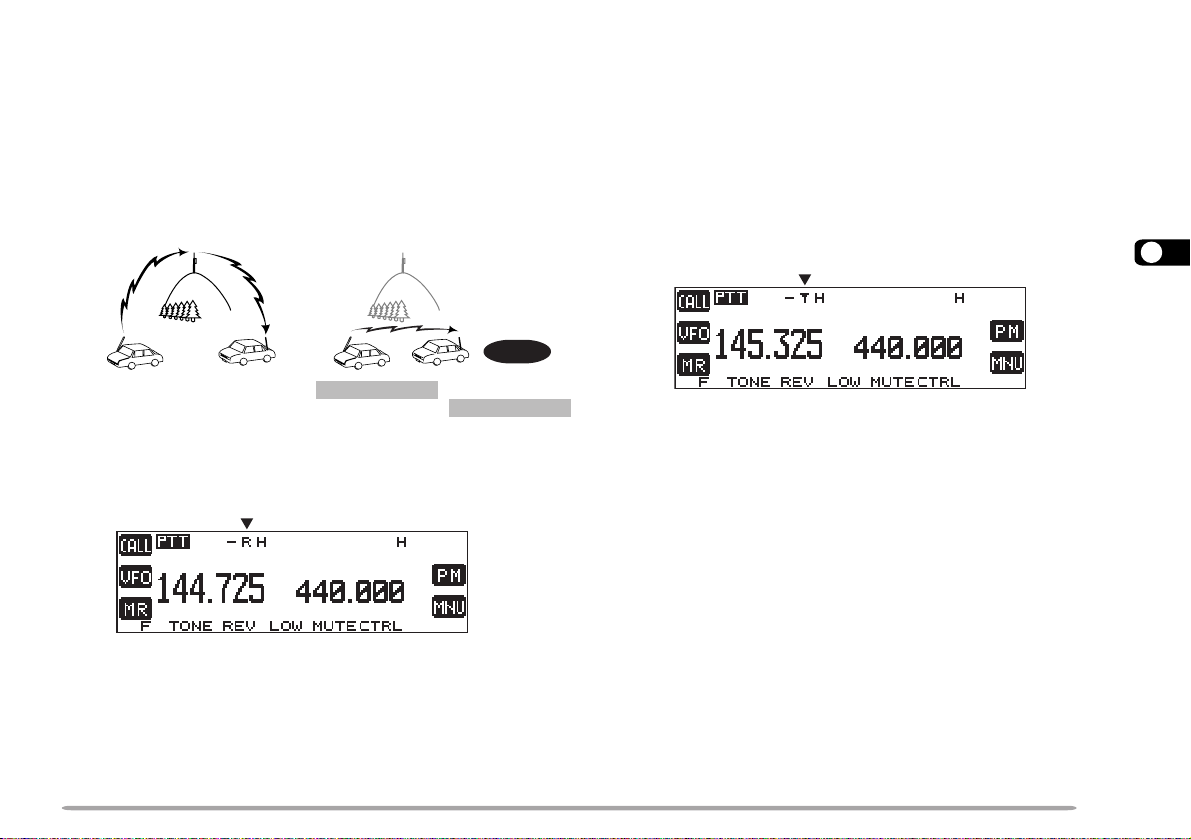
REVERSE FUNCTION
The reverse function exchanges a separate receive and
transmit frequency. So, while using a repeater, you can
manually check the strength of a signal that you receive
directly from the other station. If the station’s signal is
strong, both stations should move to a simplex frequency
and free up the repeater.
145.325 MHz
AUTOMATIC SIMPLEX CHECK (ASC)
While using a repeater, ASC periodically monitors the
strength of a signal that you receive directly from the
other station. If the station’s signal is strong enough to
allow direct contact without a repeater, the ASC indicator
on the display begins blinking.
Press [REV] (1 s) to switch the function ON.
• The ASC indicator appears when the function is ON.
6
144.725 MHz
TX: 144.725 MHz TX: 144.725 MHz
RX: 145.325 MHz RX: 145.325 MHz
TX: 144.725 MHz TX: 145.325 MHz
RX: 145.325 MHz RX: 144.725 MHz
144.725 MHz
REV ON
Press [REV] to switch the Reverse function ON (or
OFF).
• “R” appears when the function is ON.
Note:
◆
If pressing [REV] places the transmit frequency outside the allowable
range, then pressing Mic [PTT] causes an error beep to sound;
transmission is inhibited.
◆
If pressing [REV] places the receive frequency outside the allowable
range, an error beep sounds and no reversal occurs.
◆
Automatic Repeater Offset does not function while Reverse is ON.
◆
You cannot switch Reverse ON or OFF while transmitting.
• While direct contact is possible, the ASC indicator blinks.
• To quit the function, press [REV].
Note:
◆
Pressing Mic [PTT] causes the ASC indicator to quit blinking.
◆
ASC does not function if your transmit and receive frequencies are
the same (simplex operation).
◆
ASC does not function while scanning.
◆
Activating ASC while using Reverse switches Reverse OFF.
◆
If you recall a memory channel or the Call channel that contains
Reverse ON status, ASC is switched OFF.
◆
ASC causes receive audio to be momentarily intermitted every 3
seconds.
33
Page 40

TONE FREQ. ID
This function scans through all tone frequencies to
identify the incoming tone frequency on a received
signal. You may use the function to find which tone
frequency is required by your local repeater.
1 Press [TONE] to switch ON the Tone function.
• “T” appears when the Tone function is ON.
2 Press [F], [T.SEL].
6
• The current tone frequency appears and blinks.
3 Press [SCAN] to activate the Tone Freq. ID.
“T SCAN” appears and blinks.
• Scan starts when signals are received.
• To reverse the scan direction, turn the Tuning control
clockwise (upward scan) or counterclockwise
(downward scan). You can also press Mic [UP]/ [DWN].
• To quit the function, press [ESC].
• When the tone frequency is identified, the identified
frequency appears and blinks.
4 Press [OK] to program the identified frequency in
place of the currently set tone frequency.
• The Tone function will be remained ON. You may press
[TONE] to switch the Tone function OFF.
• Press [ESC] if you do not want to program the identified
frequency.
• Press [SCAN] while the identified frequency is blinking,
to resume scanning.
34
Page 41

MEMORY CHANNELS
retemaraP
&xelpmiS
retaepeR
tilps-ddO
ycneuqerfevieceR
seY
seY
ycneuqerftimsnarTseY
ycneuqerfenoTseYseY
NOenoTseYseY
ycneuqerfSSCTCseYseY
NOSSCTCseYseY
edocSCDseYseY
NOSCDseYseY
noitceridtesffOseYA/N
ycneuqerftesffOseYA/N
NOesreveRseYA/N
ezispetsycneuqerFseYseY
tuokcollennahcyromeMseYseY
emanlennahcyromeMseYseY
noitcelesedomMA/MFseYseY
In memory channels, you can store frequencies and
related data that you often use. Then you need not
reprogram those data every time. You can quickly recall
a programmed channel by simple operation. A total of
200 memory channels are available for bands A and B.
SIMPLEX & REPEATER OR ODD-SPLIT MEMORY
CHANNEL?
You can use each memory channel as a simplex &
repeater channel or as an odd-split channel. Store only
one frequency to use as a simplex & repeater channel or
two separate frequencies to use as an odd-split channel.
Select either application for each channel depending on
the operations you have in mind.
Simplex & repeater channel allows:
• Simplex frequency operation
• Repeater operation with a standard offset
(If an offset direction is stored)
Odd-split channel allows:
• Repeater operation with a non-standard offset
Note:
◆
Not only can you store data in memory channels, but you can also
overwrite existing data with new data.
◆
If you have recalled a memory channel on the non-control band
(A or B), you cannot select the same channel on the control band to
program data.
The data listed below can be stored in each memory
channel:
7
Yes: Can be stored in memory.
N/A: Cannot be stored in memory.
35
Page 42
STORING SIMPLEX FREQUENCIES OR STANDARD
REPEATER FREQUENCIES
1 Select the desired band.
2 Press [VFO].
3 Select the desired frequency.
4 If storing a standard repeater frequency, select the
following data:
• Offset direction {page 29}
7
• Tone ON, if necessary {page 30}
• Tone frequency, if necessary {page 30}
If storing a simplex frequency, you may select other
related data (CTCSS ON, CTCSS freq., etc.).
5 Press [F].
• A memory channel number appears and blinks.
” indicates the current channel is empty while “ ”
•“
indicates the channel contains data.
6 Turn the Tuning control, or press Mic [UP]/ [DWN], to
select the desired memory channel.
7 Press [M.IN] .
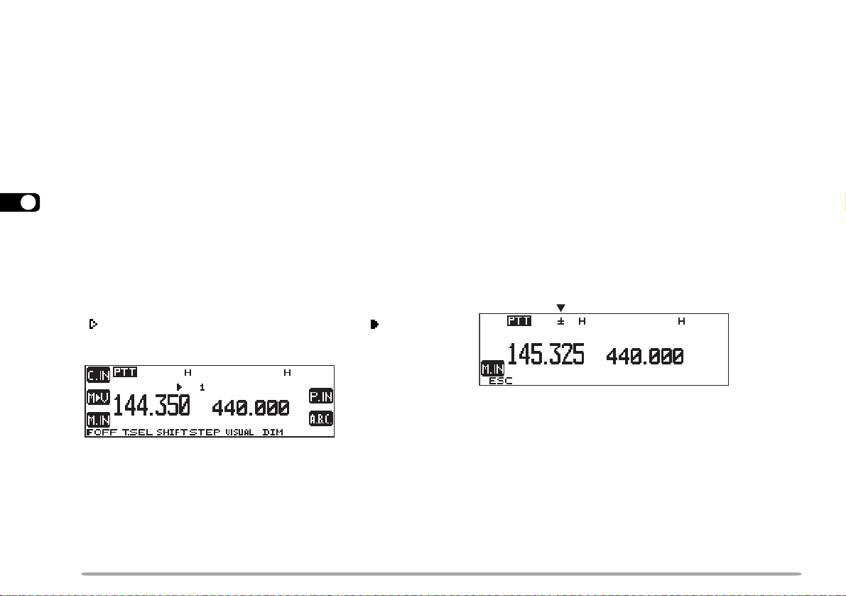
STORING ODD-SPLIT REPEATER FREQUENCIES
Some repeaters use a receive and transmit frequency
pair with a non-standard offset. If you store two separate
frequencies in a memory channel, you can operate on
those repeaters without programming the offset
frequency and direction.
1 Select the desired receive frequency and related data
by using steps 1 to 4 given for simplex or standard
repeater frequencies.
2 Press [F].
3 Turn the Tuning control, or press Mic [UP]/ [DWN], to
select the desired memory channel.
4 Press [M.IN] (1 s).
•“±” appears.
5 Select the desired transmit frequency.
6 Press [M.IN].
Note:
◆
When you recall an odd-split memory channel, “±” appears on the
display. To confirm the transmit frequency, press [REV].
◆
Transmit Offset status and Reverse status are not stored in an oddsplit memory channel.
36
Page 43
RECALLING A MEMORY CHANNEL
CLEARING A MEMORY CHANNEL
1 Select band A or B.
2 Press [MR] to enter Memory Recall mode.
• The memory channel used last is recalled.
3 Turn the Tuning control, or press Mic [UP]/ [DWN], to
select the desired memory channel.
• You cannot recall an empty memory channel.
• To restore VFO mode, press [VFO].
If using a MC-53DM, you can also use its keypad to
recall a desired memory channel. First program one of
the Mic PF keys as the ENTER key {page 62}. In
Memory Recall mode press [ENTER], then enter the
channel number. To recall channel 3, for example, press
[ENTER], [0], [0], [3].
Note:
◆
When you recall an odd-split memory channel, “±” appears on the
display. Press [REV] to display the transmit frequency.
◆
After recalling a memory channel, you may program data such as
Tone or CTCSS. These settings, however, are cleared once you
select another channel or the VFO mode. To permanently store the
data, overwrite the channel contents {page 36}.
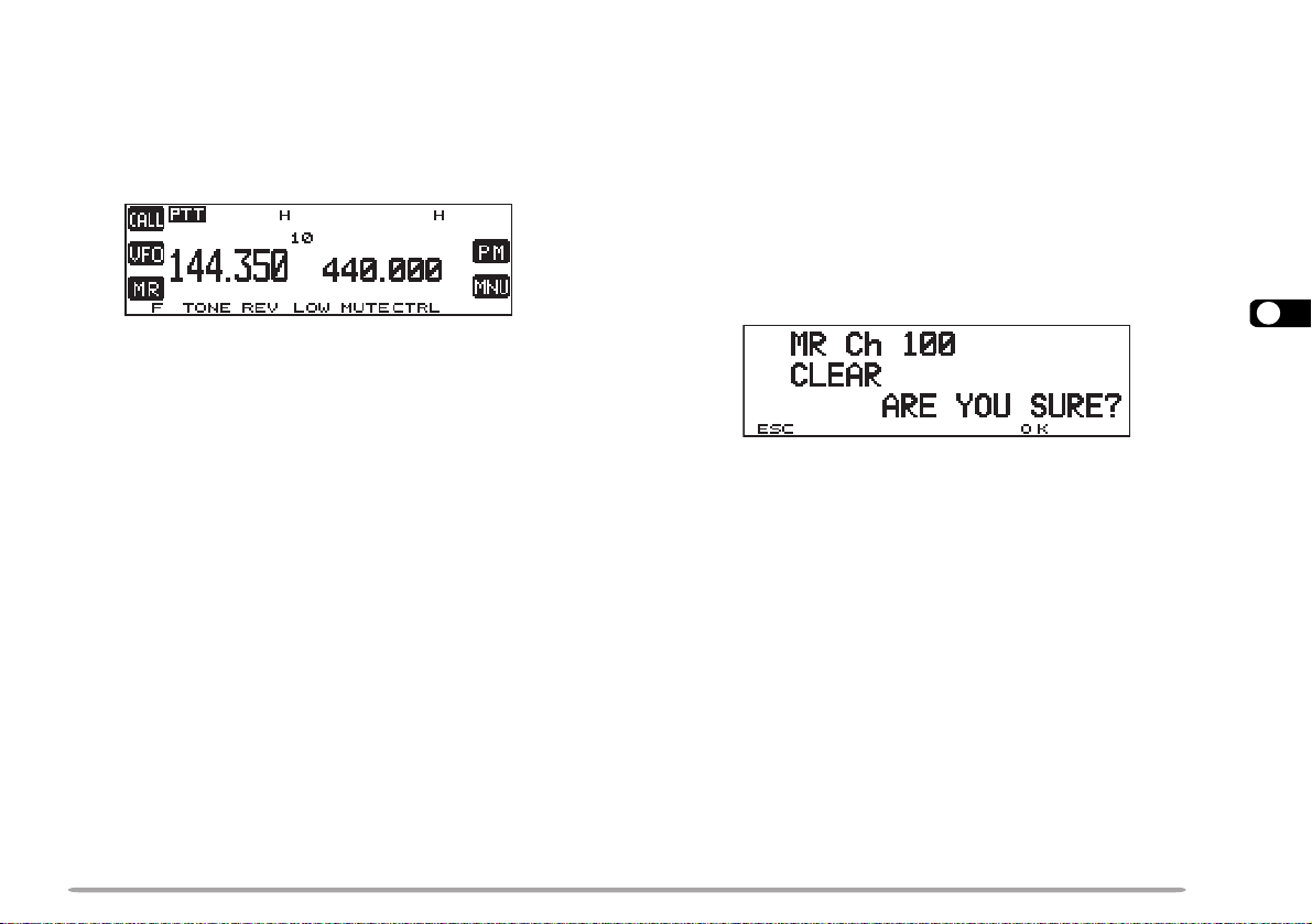
Use the following procedure to clear an individual
memory channel. Full Reset {page 41} is a quick way to
clear all memory channels.
1 Recall the desired memory channel.
2 Switch OFF the power to the transceiver.
3 Press [MHz] ( Tuning control)+ POWER ON.
• A confirmation message appears.
• To quit clearing the memory channel, press [ESC].
4 Press [OK].
Note:
◆
If you have recalled a memory channel on the non-control band (A or
B), you cannot select the same channel on the control band to clear.
◆
When in Channel Display mode, you cannot clear any memory
channel.
7
37
Page 44

NAMING A MEMORY CHANNEL
You can name memory channels using up to 8
alphanumeric characters. When you recall a named
memory channel, its name appears above the frequency.
Names can be call signs, repeater names, cities, names
of people, etc.
1 Recall the desired memory channel.
2 Press [MNU] to enter Menu mode.
cc
3 Press [
7
[OK].
4 Press [
press [OK].
5 Press [
then press [OK].
• The display for entering a memory name appears; the
first digit blinks.
dd
c]/ [
d] to select “RADIO (1–)”, then press
cc
dd
cc
dd
c]/ [
d] to select “MEMORY (1–4–)”, then
cc
dd
cc
dd
c]/ [
d] to select “MEMORY NAME (1–4–4)”,
cc
dd
8 Repeat steps 6 and 7 to enter up to 8 digits.
ciremunahplafostesehtgnomasehctiwS
.sretcarahcIICSAlaicepsdna
neewtebsehctiwS
.srettel
.gniknilb
latipacdnallams
tatigidehtseteleD
sirosrucehthcihw
yltnerrucehtstresnI
.retcarahcdetceles
DNABtfel(
)LES
,)ylnoE007D-MT(sretteldetnecca,sretcarahc
yromeMslecnaC
.yrtnEemaN
.tigidtsrifeht
9 Press [OK] to complete the setting.
10 Press [MNU] to exit Menu mode.
The keypad on the MC-53DM also is available to enter
alphanumeric characters in step 6. See page 18.
Note:
◆
You can also name the Program Scan {page 52} and DTMF
{page 60} channels, but you cannot name the Call channel
{page 39}.
◆
You can assign names only to memory channels in which you have
stored frequencies and related data.
◆
The stored names can be overwritten by repeating steps 1 to 10.
◆
The stored names also are erased by clearing memory channels.
rosrucehtsesuaC
.drawkcabevomot
dnastigidllasraelC
otrosrucehtskcab
6 Turn the Tuning control to select the first digit.
• You can enter alphanumeric characters plus special
ASCII characters.
7 Press [
• The cursor moves to the next digit.
aa
a].
aa
38
Page 45
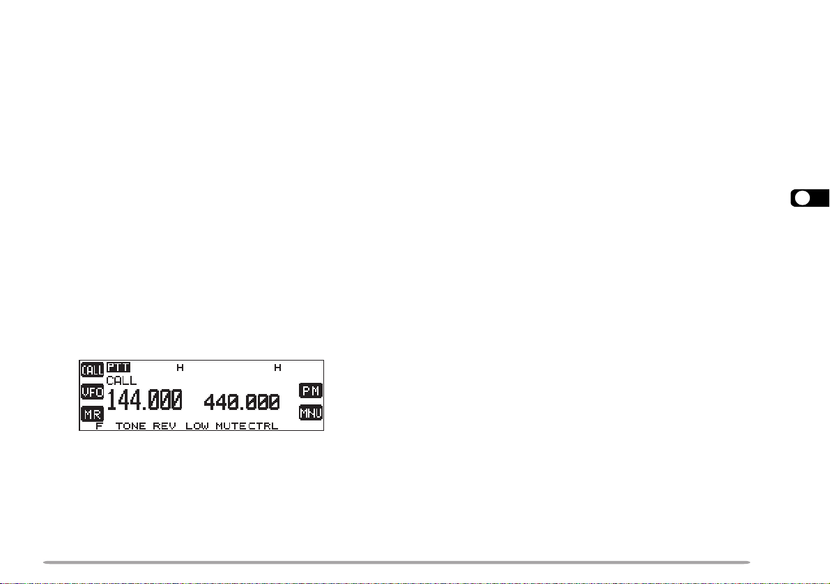
CALL CHANNEL
The Call channel can always be selected quickly no
matter what mode the transceiver is in. For instance,
you may use the Call channel as an emergency
channel within your group. In this case, the Call/VFO
scan {page 54} will be useful.
The default frequency stored in the Call channel is
144.000 MHz for the VHF band. The default on the UHF
band is 440.000 MHz or 430.000 MHz depending on the
market versions. The Call channel can be
reprogrammed either as a simplex & repeater or oddsplit channel.
Note: Unlike channels 1 to 200 the call channel cannot be cleared.
■ Recalling the Call Channel
1 Select the desired band.
2 Press [CALL] to recall the Call channel.
• “CALL” appears.
• To restore the previous mode, press [CALL] again.
■ Reprogramming the Call Channel
1 Select the desired band.
2 Press [VFO].
3 Select the desired frequency and related data
(Tone, CTCSS, etc.).
• When you program the Call channel as an odd-split
channel, select a receive frequency.
4 Press [F], [C.IN].
• The selected frequency and related data are stored
in the Call channel.
• The previous mode is restored.
• When programming as an odd-split channel, press
[F], [C.IN] (1 s) instead; “±” appears.
To also store a transmit frequency, proceed to the
next step.
5 Select the desired transmit frequency.
6 Press [C.IN].
• The transmit frequency is stored in the Call channel,
and the previous mode is restored.
Note:
◆
Transmit Offset status and Reverse status are not stored in an
odd-split Call channel.
◆
To store data other than frequencies, select the data in step 3 not
step 5.
7
39
Page 46

MEMORY-TO-VFO TRANSFER
tceleSdnab-buStceleSOFVnacSOFV
erotSyromeMerotSMPllaceRMP
OFV-ot-yromeM
refsnarT
teseRMP/lluF/laitraP
eziSpetSycneuqerF
egnahC
egnahCpetSzHM01/1kcoLlortnoc-llA
CHANNEL DISPLAY
You may sometimes want to search for other stations or
a clear frequency, near the frequency stored in a
memory channel or the Call channel. In this case first
transfer the contents of a memory channel or the Call
channel to the VFO.
1 Recall the desired memory channel or the Call
channel.
2 Press [F], [M
7
• The entire contents of the memory channel or the Call
channel are copied to the VFO.
Note:
◆
A transmit frequency from an odd-split memory channel or odd-split
Call channel is not transferred to the VFO. To transfer a transmit
frequency, press [REV], then press [F], [M
◆
Lockout status and memory names are not copied from a memory
channel to the VFO.
◆
If you recall the Call channel in step 1, simply turning the Tuning
Control or pressing Mic [UP]/ [DWN] also transfers the contents to
the VFO. The frequency, however , is changed by one step.
ss
sV].
ss
ss
s
ss
V].
When in this mode, the transceiver displays only
memory channel numbers (and memory names if stored)
instead of frequencies.
1 Press [MNU] to enter Menu mode.
cc
2 Press [
dd
c]/ [
d] to select “RADIO (1–)”, then press
cc
dd
[OK].
cc
3 Press [
dd
c]/ [
d] to select “MEMORY (1–4–)”, then
cc
dd
press [OK].
cc
4 Press [
dd
c]/ [
d] to select “CHANNEL DISPLAY (1–4–
cc
dd
2)”, then press [OK].
cc
5 Press [
dd
c]/ [
d] to switch the function ON (or OFF).
cc
dd
6 Press [OK] to complete the setting.
7 Press [MNU] to exit Menu mode.
Note: You cannot switch this function ON unless you can recall any
channel on both bands A and B.
When in Channel Display mode, you cannot use the
following functions:
40
Page 47

PARTIAL OR FULL RESET?
If your transceiver seems to be malfunctioning,
initializing the transceiver may resolve the problem. Use
Full Reset to initialize all settings that you have
customized. Partial (VFO) Reset does not initialize the
following settings:
slennahcyromeMsemanlennahcyromeM
tuokcollennahcyromeMslennahcllaC
slennahcnacsmargorPslennahcMP
slennahcyromemFMTD
seman
lennahcyromemFMTD
1 Press [MNU] to enter Menu mode.
cc
2 Press [
dd
c]/ [
d] to select “RADIO (1–)”, then press
cc
dd
[OK].
cc
3 Press [
dd
c]/ [
d] to select “AUX (1–9–)”, then press
cc
dd
[OK].
cc
4 Press [
dd
c]/ [
d] to select “RESET (1–9–7)”, then
cc
dd
press [OK].
7
Some of the VFO factory defaults are listed below:
retemaraP AdnaB BdnaB
.qerfOFVzHM000.441
pets.qerF
/.A.S.U(zHk5
zHk5.21ro)adanaC
zHk52
.qerfenoTzH5.88zH5.88
cc
5 Press [
dd
c]/ [
d] to select Partial (VFO) Reset, PM
cc
dd
Reset {page 45}, or Full Reset, then press [OK].
• A confirmation message appears.
zHM000.044
ro)adanaC/.A.S.U(
• Press [ESC] to quit resetting.
6 Press [OK].
zHM000.034
After switching the power OFF, you may press [VFO]+
POWER ON for Partial Reset, or [MR]+ POWER ON for
Full Reset. This allows you to skip steps 1 to 5.
You can also use the RESET button to perform Full
Reset. See page 12.
Note: When in All-control Lock or Channel Display mode, you cannot
perform Partial Reset nor Full Reset.
41
Page 48
PROGRAMMABLE MEMORY (PM)
dnabXT dnablortnoC
rewoptuptuotimsnarT egnahCdnaBotuA
remmiDyalpsiD
snoitcelesunemehtfoynaM
)–1(OIDARrednu
1
snoitcelesunemehtfotsoM
)–2(VTSSrednu
1
snoitcelesunemehtfotsoM
)–3(SRPArednu
1
snoitcelesunemehtfotsoM
)–4(DNAMMOCYKSrednu
2,1
Programmable Memory (PM) stores virtually all settings
currently set on the transceiver. This transceiver
provides 5 PM channels to store 5 sets of transceiver
configurations. Later you can quickly recall one of these,
depending on the operations in your mind or the
operating environment.
PROGRAMMABLE INFORMATION
The following settings can be separately stored for band
8
A and B:
ycneuqerfOFV edomOFV
edomllaceRyromeM edomlennahCllaC
noitceridtesffO ycneuqerftesffO
NOesreveR kcehCxelpmiScitamotuA
NOenoT ycneuqerfenoT
NOSSCTC ycneuqerfSSCTC
NOSCD edocSCD
1
TM-D700E only
42
timilycneuqerfreppU
ezispetsycneuqerF edomMA/MF
)OFVelbammargorProf(
1
noitaivedXTworran/ediW
The following settings are shared by both band A and B:
1
The menu items listed below will not be stored:
• 1–4–1, Auto PM Channel Store
• 1–4–3, Memory Channel Lockout
• 1–4–4, Memory channel name
• 1–5–1, DTMF Number Store
• 1–6–3, Time
• 1–6–4, Date
• 1–7–6, Repeater function
• 1–9–5, COM port
• 1–9–7, Reset
• 1–A–3, Remote Control
timilycneuqerfrewoL
)OFVelbammargorProf(
• 2–8, SSTV mode
• 3–4, My position
• 3–9, Status text
• 4–4, Sky Command mode
2
U.S.A./ Canada only
Page 49

APPLICATION EXAMPLES
The following are examples of how you might use Programmable Memory. These examples may not represent
applications useful to you, but you will understand the flexibility of this function.
You share your transceiver with other members in
your family or club. However, each individual has
personal preferences for how they like to set various
functions. You have to keep changing many settings
each time you use the transceiver.
While operating mobile on the way to work every
morning, you prefer a silent transceiver that does not
interrupt the morning calm. In addition, you feel that a
bright display is a waste of electricity in sunlight.
At night when driving home, you realize the Beep
function truly serves a purpose and you feel it is nice
to see a bright display after dark.
You cannot figure out how you can make the
transceiver exit the current mode.
Situation 1
Situation 1
Situation 2
Situation 2
Situation 3
Situation 3
Solution
Solution
Because 5 PM channels are available, up to 5
persons can separately program the transceiver and
store their customized environment. Then each
person can quickly change to his or her favorite
settings, simply by recalling a PM channel.
It is too much trouble to change back the settings
after somebody else has reconfigured them. So this
application may avoid having a feature-rich
transceiver but never using many useful features.
Solution
Solution
In two PM channels, store the same operating data
such as frequency, offset, tone, etc., and store
different settings for the Display Dimmer and Beep
functions. Then you can quickly recall the best
settings for day or night operating.
Solution
Solution
Simply recall PM channel 1 that contains an exact
copy of the transceiver default environment. You will
not lose the contents of any memory channels.
8
43
Page 50
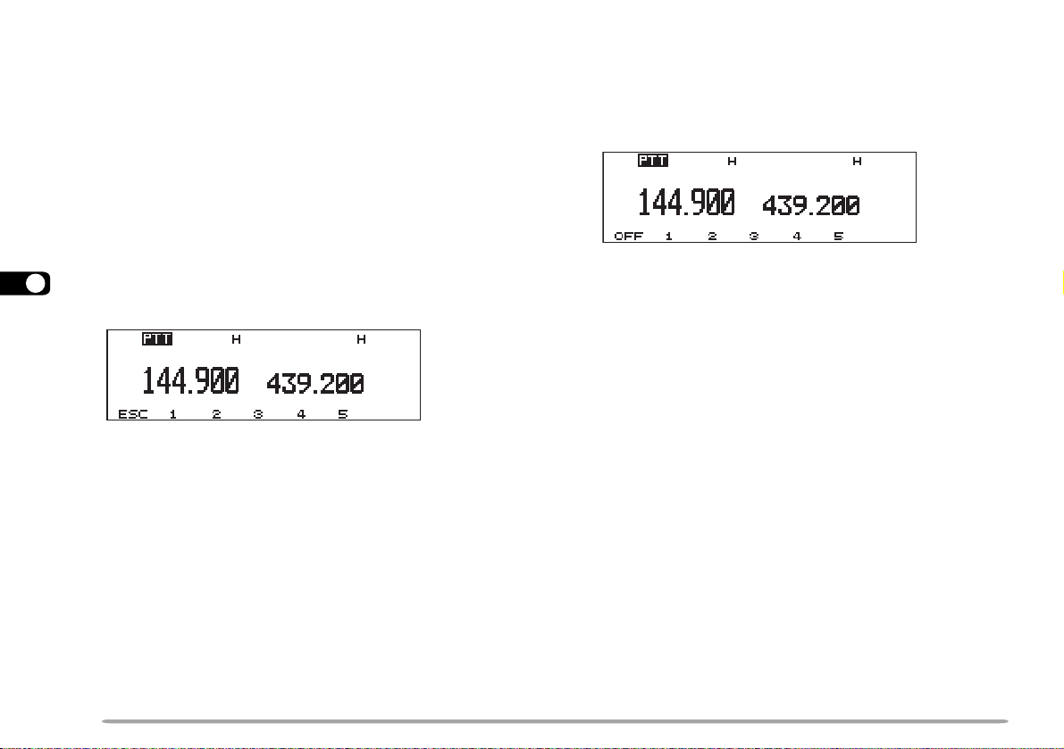
STORING IN PM CHANNELS
RECALLING A PM CHANNEL
1 Confirm that the following conditions have been
satisfied:
• The transceiver is in the receive mode.
• Scan is not being used.
• Microphone Control is OFF.
2 Configure the transceiver as you like.
• For the items that can be stored, see page 42.
3 Press [F], [P.IN].
• The PM channel numbers 1 to 5 appear and blink at the
8
bottom of the display.
4 Press [1] to [5] corresponding to the desired PM
channel.
• The settings listed in page 42 are stored in the PM
channel.
1 Press [PM].
• The PM channel numbers 1 to 5 appear at the bottom of
the display.
2 Press [1] to [5] corresponding to the desired PM
channel.
• The contents of the selected channel are recalled.
• The current PM channel number appears at the upper
right corner. “s” before “PM” indicates that Auto PM
Store mode {page 45} has been selected.
• To exit PM Recall mode, press [PM], then press [OFF].
Note: You cannot recall a PM channel while transmitting.
44
Page 51
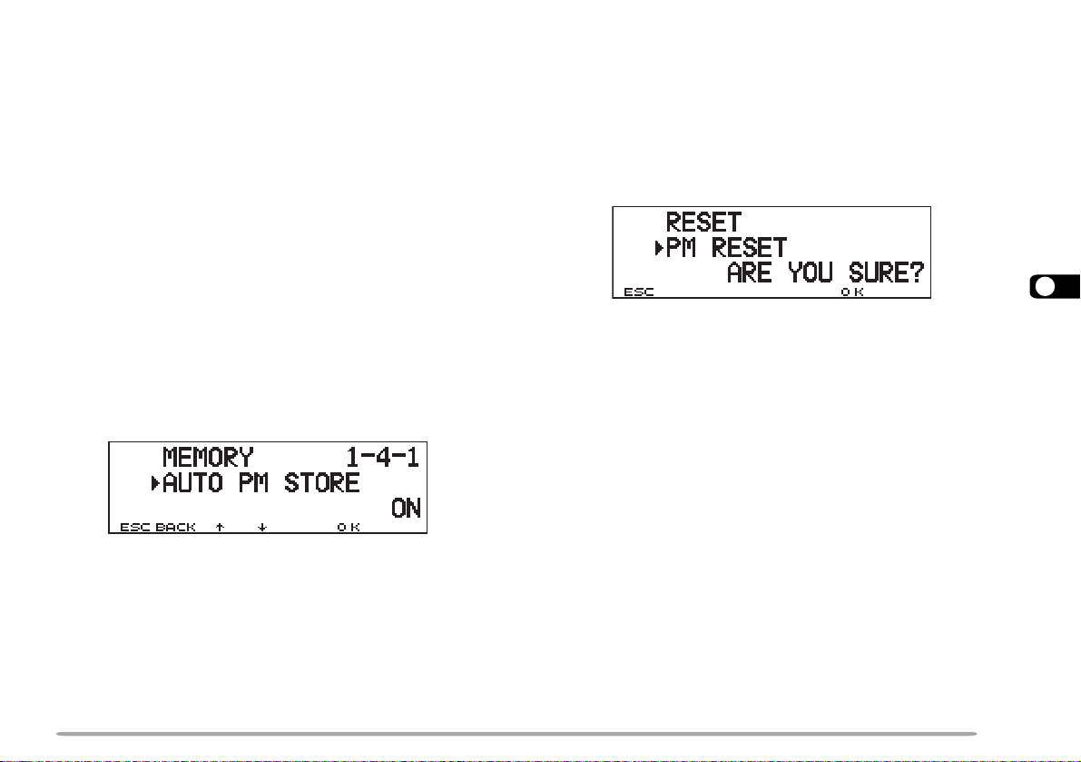
AUTO PM CHANNEL STORE
PM CHANNEL RESET
After you recalled a PM channel, this function
automatically overwrites the current PM channel with the
present operating environment when:
• You recall another PM channel.
• You press [OFF].
• You switch OFF the transceiver.
The factory default of this function is ON.
1 Press [MNU] to enter Menu mode.
cc
2 Press [
dd
c]/ [
d] to select “RADIO (1–)”, then press
cc
dd
[OK].
cc
3 Press [
dd
c]/ [
d] to select “MEMORY (1–4–)”, then
cc
dd
press [OK].
cc
4 Press [
dd
c]/ [
d] to select “AUTO PM STORE (1–4–1)”,
cc
dd
then press [OK].
cc
5 Press [
dd
c]/ [
d] to switch the function ON (default) or
cc
dd
OFF.
6 Press [OK] to complete the setting.
7 Press [MNU] to exit Menu mode.
If you want to reprogram the PM channels from the
beginning, reset all the PM channels to the factory
defaults.
1 Press [PM]+ POWER ON.
• A confirmation message appears.
8
• Press [ESC] to quit resetting.
2 Press [OK].
You can also use Menu 1–9–7 (RESET) to reset the PM
channels. See page 41.
45
Page 52

SCAN
epyTnacS egnaRnacS
nacSOFVdnabehtnoelbanutseicneuqerfllA
nacSyromeM
yromemehtniderotsseicneuqerF
slennahc
nacSpuorG
yromemehtniderotsseicneuqerF
ehtotgnolebhcihwslennahc
puorgdeificeps
nacSmargorP
egnarehtniseicneuqerfllA
dnabehtnodetceles
nacSzHMegnarzHM1anihtiwseicneuqerfllA
nacSOFV/llaC
OFVtnerrucehtsulplennahcllaC
ycneuqerf
nacSyromeM/llaC
detcelesehtsulplennahcllaC
lennahcyromem
Scan is a useful feature for hands-off monitoring of your
favorite frequencies. Becoming comfortable with all
types of Scan will increase your operating efficiency.
145.430 MHz
9
Stop
46
This transceiver provides the following types of scans
plus Visual Scan {page 47}. Visual Scan graphically and
simultaneously shows how frequencies in a specific
range are busy.
Note:
◆
Adjust the squelch level before using Scan. Selecting a squelch level
too low could cause Scan to stop immediately.
◆
While using CTCSS or DCS, Scan stops for any signal received;
however, you will hear audio only when the signal contains the same
CTCSS tone or DCS code that you selected.
◆
When using S-meter Squelch, Scan stops when the received signal
strength matches or exceeds the S-meter setting. Scan resumes
2 seconds after the signal level drops below the S-meter setting.
◆
Pressing and holding Mic [PTT] causes Scan to temporarily stop if it
is functioning on a non TX band.
◆
Starting Scan switches OFF the Automatic Simplex Check.
Page 53

VISUAL SCAN
While you are receiving, Visual Scan allows you to
monitor frequencies near the current operating
frequency. Visual Scan graphically and simultaneously
shows how all frequencies in the selected range are
busy. You will see up to 21 segments, for each channel,
that represent 7 S-meter levels (3 segments per level).
You will determine the scan range by selecting the
center frequency and the number of channels. The
default number of channels is 61.
S-meter
level
7
6
5
4
3
2
1
Cursor
7
6
5
4
3
2
1
Mode 1 (31 ch)
Frequency channel
Move the cursor to this
position to receive this signal
Mode 2 (61 ch)
■ Selecting the Number of Channels
1 Press [MNU] to enter Menu mode.
cc
2 Press [
dd
c]/ [
d] to select “RADIO (1–)”, then press
cc
dd
[OK].
cc
3 Press [
dd
c]/ [
d] to select “AUX (1–9–)”, then press
cc
dd
[OK].
cc
4 Press [
dd
c]/ [
d] to select “VISUAL SCAN (1–9–2)”,
cc
dd
then press [OK].
cc
5 Press [
dd
c]/ [
d] to select 31, 61 (default), 91, or
cc
dd
181.
6 Press [OK] to complete the setting.
7 Press [MNU] to exit Menu mode.
9
47
Page 54

■ Using Visual Scan
1 Select the desired band.
2 Turn the Tuning control, or press Mic [UP]/
[DWN], to select the operating frequency.
• This frequency will also be used as the center
frequency.
3 Press [F], [VISUAL] to start Visual Scan.
9
• To halt Scan, press [PAUSE]. “PAUSE” appears and
blinks. Press [PAUSE] again to resume.
4 To change the operating frequency, turn the
Tuning control or press Mic [UP]/ [DWN].
• The displayed frequency changes and the cursor
moves.
• Press [SET] to use the changed operating frequency
as the center frequency.
• Press [RESET] to restore the previous operating
frequency.
5 To quit Visual Scan, press [ESC].
Note:
◆
If you start Visual Scan in Memory Recall mode, the memory
channel frequencies will be scanned.
◆
If you start Visual Scan after recalling the Call channel, the call
channel frequency will be used as the center frequency.
◆
If the frequency range specified for Program Scan or Program
VFO is narrower than the range specified for Visual Scan, the
range for Program Scan or VFO will be used for Visual Scan.
◆
Visual Scan stops while transmitting.
◆
Starting Visual Scan switches Automatic Band Change OFF.
◆
If you start Visual Scan in one of the following conditions, you
cannot receive in the current operating frequency. To use this
frequency, press [PAUSE] to halt Scan.
•
Memory Recall or Call Channel mode
•
A frequency in the 118, 220, or 1200 MHz band was selected
in VFO mode.
◆
Depending on conditions, Visual Scan and the conventional Smeter may indicate different signal strength levels.
48
Page 55

SELECTING SCAN RESUME METHOD
The transceiver stops scanning at a frequency (or
memory channel) on which a signal is detected. It then
continues scanning according to which resume mode
you select. You can choose one of the following modes.
The default is Time-operated mode.
• Time-Operated mode
The transceiver remains on a busy frequency (or
memory channel) for approximately 5 seconds, and
then continues to scan even if the signal is still
present.
• Carrier-Operated mode
The transceiver remains on a busy frequency (or
memory channel) until the signal drops out. There is
a 2 second delay between signal drop-out and scan
resumption.
• Seek mode
The transceiver remains on a busy frequency (or
memory channel) even after the signal drops out and
does not automatically resume scanning.
Note: To temporarily stop scanning and monitor weak signals, press the
Mic PF key assigned the Monitor function {page 62}. Press the PF key
again to resume scanning.
1 Press [MNU] to enter Menu mode.
cc
2 Press [
dd
c]/ [
d] to select “RADIO (1–)”, then press
cc
dd
[OK].
cc
3 Press [
dd
c]/ [
d] to select “AUX (1–9–)”, then press
cc
dd
[OK].
cc
4 Press [
dd
c]/ [
d] to select “SCAN RESUME (1–9–1)”,
cc
dd
then press [OK].
cc
5 Press [
dd
c]/ [
d] to select Time-Operated (default),
cc
dd
Carrier-Operated, or Seek.
6 Press [OK] to complete the setting.
7 Press [MNU] to exit Menu mode.
9
49
Page 56

VFO SCAN
MEMORY SCAN
VFO Scan monitors all frequencies tunable on the band,
using the current frequency step size.
1 s
9
1 Select the desired band.
2 Press [VFO] (1 s).
• Scan starts at the frequency currently displayed.
• The 1 MHz decimal blinks while scanning is in progress.
• To reverse the scan direction, turn the Tuning control
clockwise (upward scan) or counterclockwise
(downward scan). You can also press Mic [UP]/ [DWN].
3 To quit VFO Scan, press [VFO] again.
Use Memory Scan to monitor all memory channels
programmed with frequency data.
1 s
1 Select band A or B.
2 Press [MR] (1 s).
• Scan starts with the channel last recalled.
• The 1 MHz decimal blinks while scanning is in progress.
• To reverse the scan direction, turn the Tuning control
clockwise (upward scan) or counterclockwise
(downward scan). You can also press Mic [UP]/ [DWN].
3 To quit Memory Scan, press [MR] again.
Note:
◆
At least 2 or more memory channels must contain data and must not
be locked out.
◆
The L0 to L9 and U0 to U9 memory channels are not scanned.
◆
You can also start Memory Scan when in Channel Display mode.
While Scan is being interrupted, the channel number blinks.
50
Page 57

■ Locking Out a Memory Channel
02~1.soN021~101.soN
04~12.soN041~121.soN
06~14.soN061~141.soN
08~16.soN081~161.soN
001~18.soN002~181.soN
Select memory channels that you prefer not to
monitor while scanning.
1 Recall the desired memory channel.
2 Press [MNU] to enter Menu mode.
cc
3 Press [
dd
c]/ [
d] to select “RADIO (1–)”, then press
cc
dd
[OK].
cc
4 Press [
dd
c]/ [
d] to select “MEMORY (1–4–)”, then
cc
dd
press [OK].
cc
5 Press [
dd
c]/ [
d] to select “LOCKOUT (1–4–3)”,
cc
dd
then press [OK].
cc
6 Press [
dd
c]/ [
d] to switch Lockout ON (or OFF).
cc
dd
7 Press [OK] to complete the setting.
8 Press [MNU] to exit Menu mode.
• A star appears to indicate the channel has been
locked out.
Note: The L0 to L9 and U0 to U9 memory channels cannot be
locked out.
GROUP SCAN
For the purpose of Group Scan, the 200 memory
channels are divided into 10 groups, with each group
containing 20 channels. Group Scan monitors only the
20 channels which belong to the specified group. The
channels are grouped as below:
1 Recall one of the memory channels in the desired
group.
2 Press [MHz] (Tuning control) (1 s).
• Scan starts with the channel last recalled.
• The 1 MHz decimal blinks while scanning is in progress.
• To reverse the scan direction, turn the Tuning control
clockwise (upward scan) or counterclockwise
(downward scan). You can also press Mic [UP]/ [DWN].
3 To quit Group Scan, press [MHz] again.
Note:
◆
At least 2 or more memory channels in the specified group must
contain data and must not be locked out.
◆
You can also start Group Scan when in Channel Display mode.
While Scan is being interrupted, the channel number blinks.
9
51
Page 58
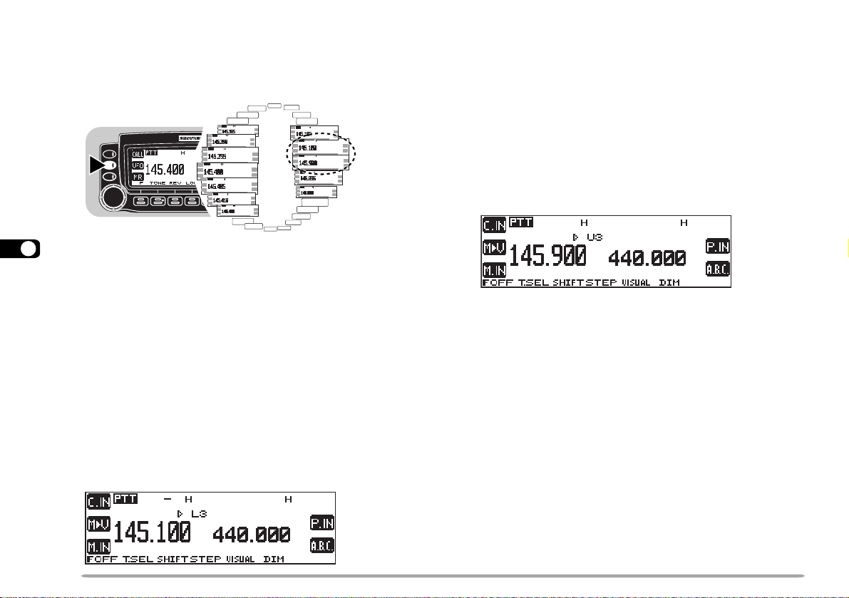
PROGRAM SCAN
Program Scan is identical with VFO Scan except that
you select the frequency range of the scan.
1 s
9
■ Setting Scan Limits
You can store up to 10 scan ranges in memory
channels L0/U0 to L9/U9.
1 Select the desired band.
2 Press [VFO].
3 Select the desired frequency as the lower limit.
4 Press [F].
• A memory channel number appears and blinks.
5 Turn the Tuning control, or press Mic [UP]/
[DWN], to select a channel in the range L0 to L9.
6 Press [M.IN] .
• The lower limit is stored in the channel.
7 Select the desired frequency as the upper limit.
8 Press [F].
9 Turn the Tuning control, or press Mic [UP]/
[DWN], to select a matching channel in the range
U0 to U9.
• If you have selected for example L3 in step 5, select
U3.
10 Press [M.IN].
• The upper limit is stored in the channel.
To confirm the stored scan limits, press [MR], then
select the L and U channels.
Note:
◆
The lower limit must be lower in frequency than the upper limit.
◆
The lower and upper frequency step sizes must be equal.
◆
The lower and upper limits must be selected on the same band.
52
Page 59
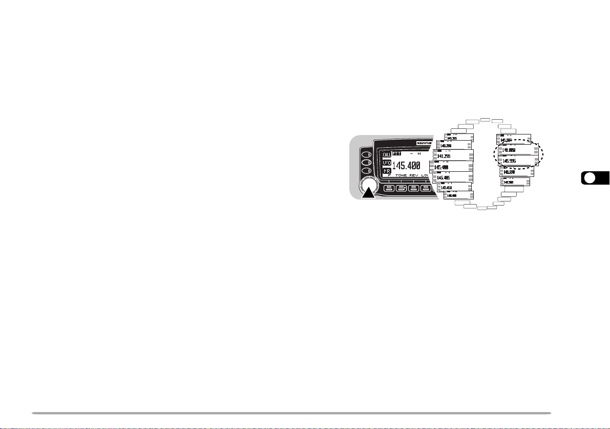
■ Using Program Scan
1 Select the appropriate band.
2 Press [VFO] .
3 Select a frequency equal to or between the
programmed scan limits.
4 Press [VFO] (1 s).
• Scan starts at the frequency currently displayed.
• The 1 MHz decimal blinks while scanning is in
progress.
• To reverse the scan direction, turn the Tuning
control clockwise (upward scan) or counterclockwise
(downward scan). You can also press Mic [UP]/
[DWN].
5 To quit Program Scan, press [VFO] again.
Note:
◆
If the step size of the current VFO frequency differs from that of
the programmed frequencies, VFO scan starts instead of
Program Scan.
◆
If the step size differs between the lower limit and the upper limit,
VFO scan starts instead of Program Scan.
◆
If the current VFO frequency is within more than one
programmed scan range, the range stored in the smallest
channel number is used.
MHz SCAN
MHz Scan monitors a 1 MHz segment of the band, using
the current frequency step size. The current 1 MHz digit
determines the limits of the scan. For example, if the
current frequency is 145.400 MHz, then the scan range
would be from 145.000 MHz to 145.995 MHz. The exact
upper limit depends on the current frequency step size.
9
1 s
1 Select the desired band.
2 Press [VFO] to select VFO mode.
3 Select a frequency within the desired 1 MHz
segment.
4 Press [MHz] (Tuning control) (1 s).
• Scan starts at the frequency currently displayed.
• The 1 MHz decimal blinks while scanning is in progress.
• To reverse the scan direction, turn the Tuning control
clockwise (upward scan) or counterclockwise
(downward scan). You can also press Mic [UP]/ [DWN].
5 To quit MHz Scan, press [MHz] again.
53
Page 60

CALL/VFO SCAN
Use Call/VFO Scan to monitor both the Call channel and
the current VFO frequency on the selected band.
1 Select the desired band.
2 Press [VFO].
3 Select the desired frequency.
4 Press [CALL] (1 s) to start Call/VFO Scan.
• The 1 MHz decimal blinks while scanning is in progress.
5 To quit Call/VFO Scan, press [CALL] again.
9
CALL/MEMORY SCAN
Use Call/Memory Scan to monitor both the Call channel
and the desired memory channel.
1 Recall the desired memory channel.
2 Press [CALL] (1 s) to start Call/Memory Scan.
• The 1 MHz decimal blinks while scanning is in progress.
• The Call channel on the same band as of the selected
memory channel is used for Scan.
3 To quit Call/Memory Scan, press [CALL] again.
Note: The memory channel last used is scanned even if it has been
locked out.
54
Page 61

CONTINUOUS TONE CODED SQUELCH SYSTEM (CTCSS)
You may sometimes want to hear calls from only specific
persons. The Continuous Tone Coded Squelch System
(CTCSS) allows you to ignore (not hear) unwanted calls
from other persons who are using the same frequency.
First select the same CTCSS tone as selected by the
other persons in your group. A CTCSS tone is
subaudible and is selectable from among the 38
standard tone frequencies.
Note: CTCSS does not cause your conversation to be private. It only
relieves you from listening to unwanted conversations.
Received
CTCSS freq.:
82.5 Hz
Not Received
CTCSS freq.:
82.5 Hz
Not Received
CTCSS freq.:
100 Hz
CTCSS: OFF
USING CTCSS
1 Press the left or right [BAND SEL] to select band A or
B.
• If necessary, press [F], then the same [BAND SEL] to
recall the sub-band.
2 Press [TONE] to activate the CTCSS function.
• “CT” appears when the CTCSS function is ON.
• Each press of [TONE] changes the selection as Tone –>
CTCSS –> DCS –> No selection.
3 Press [F], [T.SEL].
• The current CTCSS frequency appears and blinks.
cc
4 Press [
• The selectable frequencies are the same as for the tone
frequency. See the table given in “Selecting a Tone
Frequency” {page 30}.
5 Press [OK] to complete the setting.
You will hear calls only when the selected tone is
received. To answer the call, press and hold Mic [PTT],
then speak into the microphone.
Skip steps 3 to 5 if you have already programmed the
appropriate CTCSS frequency.
dd
c]/ [
d] to select a CTCSS frequency.
cc
dd
55
10
Page 62

If using a MC-53DM, you can also use its keypad to
select a CTCSS frequency. First program one of the Mic
PF keys as the ENTER key {page 62}. In step 3, press
[ENTER], then enter 01 to 38 shown in the table {page
30}. To select 79.7 Hz, for example, press [ENTER], [0],
[5].
Note:
◆
You can select a separate tone frequency for the CTCSS and Tone
functions.
◆
You cannot use the CTCSS with the Tone or DCS function.
◆
If you select a high tone frequency, receiving audio or noise that
contains the same frequency portions may cause CTCSS to function
incorrectly. To prevent noise from causing this problem, select an
appropriate noise squelch level {page 20}.
10
CTCSS FREQ. ID
This function scans through all CTCSS frequencies to
identify the incoming CTCSS frequency on a received
signal. You may find it useful when you cannot recall the
CTCSS frequency that the other persons in your group
are using.
1 Press [TONE] to switch ON the CTCSS function.
• “CTCSS” appears when the CTCSS function is ON.
2 Press [F], [T.SEL].
• The current CTCSS frequency appears and blinks.
3 Press [SCAN] to activate the CTCSS Freq. ID.
• “CT SCAN” appears and blinks.
• Scan starts when signals are received.
• To reverse the scan direction, turn the Tuning control
clockwise (upward scan) or counterclockwise
(downward scan). You can also press Mic [UP]/ [DWN].
• To quit the function, press [ESC].
• When the CTCSS frequency is identified, the identified
frequency appears and blinks.
4 Press [OK] to program the identified frequency in
place of the currently set CTCSS frequency.
• The CTCSS function will be remained ON. You may
press [TONE] to switch the CTCSS function OFF.
• Press [ESC] if you do not want to program the identified
frequency.
• Press [SCAN] while the identified frequency is blinking,
to resume scanning.
Note: Received signals are audible while scanning is in progress.
56
Page 63

DIGIT AL CODE SQUELCH (DCS)
Digital Code Squelch (DCS) is another application which
allows you to ignore (not hear) unwanted calls. It
functions the same way as CTCSS. The only
differences are the encode/ decode method and the
number of selectable codes. For DCS, you can select
from 104 different codes listed in the table.
Received
DCS code: 125
Not Received
DCS code: 125
320560231502552133314564216137
520170431212162233324664426237
620270341322362343134305726437
130370541522562643234605136347
230470251622662153544615236457
630411551342172653644325456
340511651442472463254625266
740611261542603563454235466
150221561642113173554645307
350521271152513114264565217
450131471252523214464606327
DCS code: 205
USING DCS
1 Press the left or right [BAND SEL] to select band A or
B.
• If necessary, press [F], then the same [BAND SEL] to
recall the sub-band.
2 Press [TONE] to activate the DCS function.
• “DCS” appears when the DCS function is ON.
• Each press of [TONE] changes the selection as Tone –>
CTCSS –> DCS –> No selection.
3 Press [F], [T.SEL].
• The current DCS code appears and blinks.
cc
4 Press [
[OK].
You will hear calls only when the selected code is
received. To answer the call, press and hold Mic [PTT],
then speak into the microphone.
Note: You cannot use the DCS with the Tone or CTCSS function.
dd
c]/ [
d] to select a DCS code, then press
cc
dd
11
57
Page 64
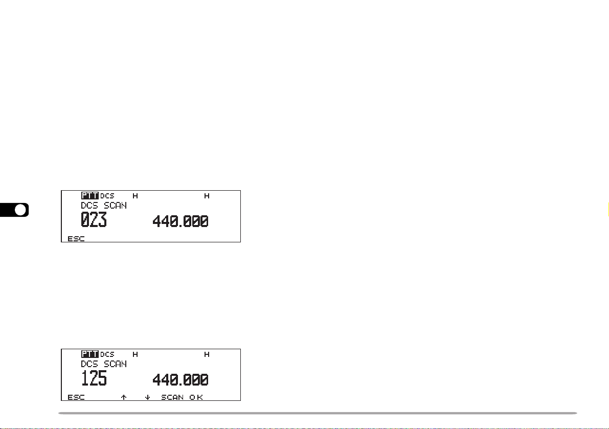
DCS CODE ID
This function scans through all DCS codes to identify the
incoming DCS code on a received signal. You may find
it useful when you cannot recall the DCS code that the
other persons in your group are using.
1 Press [TONE] to switch ON the DCS function.
• “DCS” appears when the DCS function is ON.
2 Press [F], [T.SEL].
• The current DCS code appears and blinks.
3 Press [SCAN] to activate the DCS CODE ID.
• “DCS SCAN” appears and blinks.
11
• Scan starts when signals are received.
• To reverse the scan direction, turn the Tuning control
clockwise (upward scan) or counterclockwise
(downward scan). You can also press Mic [UP]/ [DWN].
• To quit the function, press [ESC].
• When the DCS code is identified, the identified code
appears and blinks.
4 Press [OK] to program the identified code in place of
the currently set code.
• The DCS function will be remained ON. You may press
[TONE] to switch the DCS function OFF.
• Press [ESC] if you do not want to program the identified
code.
• Press [SCAN] while the identified code is blinking, to
resume scanning.
Note: Received signals are audible while scanning is in progress.
58
Page 65

DUAL TONE MULTI-FREQUENCY (DTMF) FUNCTIONS (WITH MC-53DM ONLY)
The keys on the Mic keypad function as DTMF keys; the
12 keys found on a push-button telephone plus 4
additional keys (A, B, C, D). This transceiver provides
10 dedicated memory channels. You can store a DTMF
number (16 digits max.) with a memory name (8 digits
max.) in each of the channels to recall later for a quick
call.
Some repeaters in the U.S.A. and Canada offer a
service called Autopatch. You can access the public
telephone network via such a repeater by sending DTMF
tones. For further information, consult your local
repeater reference.
MANUAL DIALING
Manual Dialing requires only two steps to send DTMF
tones.
1 Press and hold Mic [PTT].
2 Press the keys in sequence on the Mic keypad to
send DTMF tones.
• The corresponding DTMF tones are transmitted.
)zH(.qerF 9021 6331 7741 3361
796
077
258
149
123A
456B
789C
0D
■ DTMF Monitor
When pressing the Mic DTMF keys, you will not
hear DTMF tones from the speaker. You can also
make the speaker output DTMF tones each time
you press a DTMF key.
Access Menu 1–8–6 (DTMF MONITOR) and
select “ON”.
12
59
Page 66

AUTOMATIC DIALER
If you use the 10 dedicated memory channels to store
DTMF numbers, you need not remember a long string
of digits.
■ Storing a DTMF Number in Memory
Note: Audible DTMF tones from other transceivers near you (or
from your own speaker) may be picked up by your microphone.
If so, you may fail to correctly program a DTMF number .
1 Press [MNU] to enter Menu mode.
2 Select Menu 1–5–1 (STORE), then press [OK].
cc
dd
c]/ [
d] to select from channels 0 to 9,
cc
dd
aa
a].
aa
12
3 Press [
then press [OK].
• The display for entering a memory name
appears; the first digit blinks.
• To skip naming the channel, press [OK] again.
You can jump to step 8.
4 Turn the Tuning control to select a character.
• You can enter alphanumeric characters plus
special ASCII characters.
5 Press [
• The cursor moves to the next digit.
60
6 Repeat steps 4 and 5 to enter up to 8 digits.
ciremunahplafostesehtgnomasehctiwS
.sretcarahcIICSAlaicepsdna
neewtebsehctiwS
.srettel
.gniknilb
latipacdnallams
tatigidehtseteleD
sirosrucehthcihw
ehtstresnI
detcelesyltnerruc
.retcarahc
DNABtfel(
)LES
.tigid
yromeMslecnaC
.yrtnEemaN
stigidllasraelC
ehtskcabdna
tsrifehtotrosruc
7 Press [OK].
• The cursor moves to the start of the next field.
8 Press the keys in sequence on the Mic keypad to
enter a DTMF number with up to 16 digits.
• You may turn the Tuning control then [
each digit. Select a space if you want to include a
pause.
aa
a] to select
aa
9 Press [OK] to complete the programming.
10 Press [MNU] to exit Menu mode.
You can confirm the stored DTMF number by using
steps 1 to 3.
The keypad on the MC-53DM also is available to enter
alphanumeric characters in step 4. See page 18.
,)ylnoE007D-MT(sretteldetnecca,sretcarahc
rosrucehtsesuaC
.drawkcabevomot
Page 67

■ Transmitting a Stored DTMF Number
■ Selecting TX Speed
1 Press Mic [PTT]+ Mic [PF].
2 Release only Mic [PF], then press Mic [UP]/
[DWN] to select the desired DTMF memory
channel.
3 While still holding Mic [PTT], press [0] to [9]
corresponding to the channel number.
• The number stored in the channel scrolls across the
display accompanied by DTMF tones from the
speaker.
• After transmission, the frequency display is restored.
Some repeaters may not respond correctly if a DTMF
number is transmitted at fast speed. If this happens,
change the DTMF number transmission speed from
Fast (default) to Slow.
In Menu mode, access Menu 1–5–2 (TX SPEED) and
select “Slow”.
■ Selecting Pause Duration
You can also change pause duration stored in
memory channels; the default is 500 msec.
In Menu mode, access Menu 1–5–3 (PAUSE) and
select from 100, 250, 500, 750, 1000, 1500, and 2000
msec.
12
61
Page 68

PROGRAMMABLE FUNCTION (PF) KEYS
The Programmable Function keys are [PF], [MR],
[VFO], and [CALL] located on the face of the
microphone. These keys have the following default
functions:
]FP[ )1FP(tceleSdnaB
]RM[ )2FP(llaceRyromeM
]OFV[ )3FP(tceleSOFV
]LLAC[ )4FP(
If you prefer, you can change the defaults to the
following key functions:
.feR
noitcnuFyeK
egaP
13
B/A71VER33PETS46
ROTINOM91WOL12LAUSIV84
RETNE
ECIOV38LRTC71
057123NIMP44
MP44.C.B.A66
UNEM22MsV04
OFV51NI.M63
RM73NI.C93
LLAC93KCOL76
zHM02LES.T
ENOT
For the shaded functions, see the separate manual,
“SPECIALIZED COMMUNICATIONS”.
,73,03
36,65
75,55,03
ETUM27MID56
TFIHS92
.feR
noitcnuFyeK
egaP
75,55,03
62
tceleSlennahCllaC
noitcnuFyeK
LESDNAB-BUS
XD )6(
CNT )11,6,4(
TSIL )51(
NOM.P )62(
NOCB )23,52(
GSM )23~03(
SOP )02,91(
RWP
)ylno1FP(
1 Press [MNU] to enter Menu mode.
cc
2 Press [
dd
c]/ [
d] to select “RADIO (1–)”, then press
cc
dd
[OK].
cc
3 Press [
dd
c]/ [
d] to select “MIC (1–8–)”, then press
cc
dd
[OK].
cc
4 Press [
dd
c]/ [
d] to select “PF1 (1–8–1)” to “PF4 (1–8–4)”,
cc
dd
then press [OK].
)XTenoTzH0571:E007D-MT(
.feR
egaP
5 Press [
cc
dd
c]/ [
d] to select the desired function.
cc
dd
6 Press [OK] to complete the setting.
7 Press [MNU] to exit Menu mode.
71
After switching the power OFF, you may press Mic [PF]+
POWER ON. This allows you to skip steps 1 to 4. Press
Mic [MR], [VFO], or [CALL] instead of [PF] as
necessary.
Note:
◆
Without an optional VS-3 unit installed or with OFF selected in Menu
1–2–4 (VOICE), pressing the PF key programmed with Voice causes
the transceiver to announce the current frequency using beeps of
91
different frequencies.
◆
To restore the default functions, perform Full Reset {page 41}.
Page 69
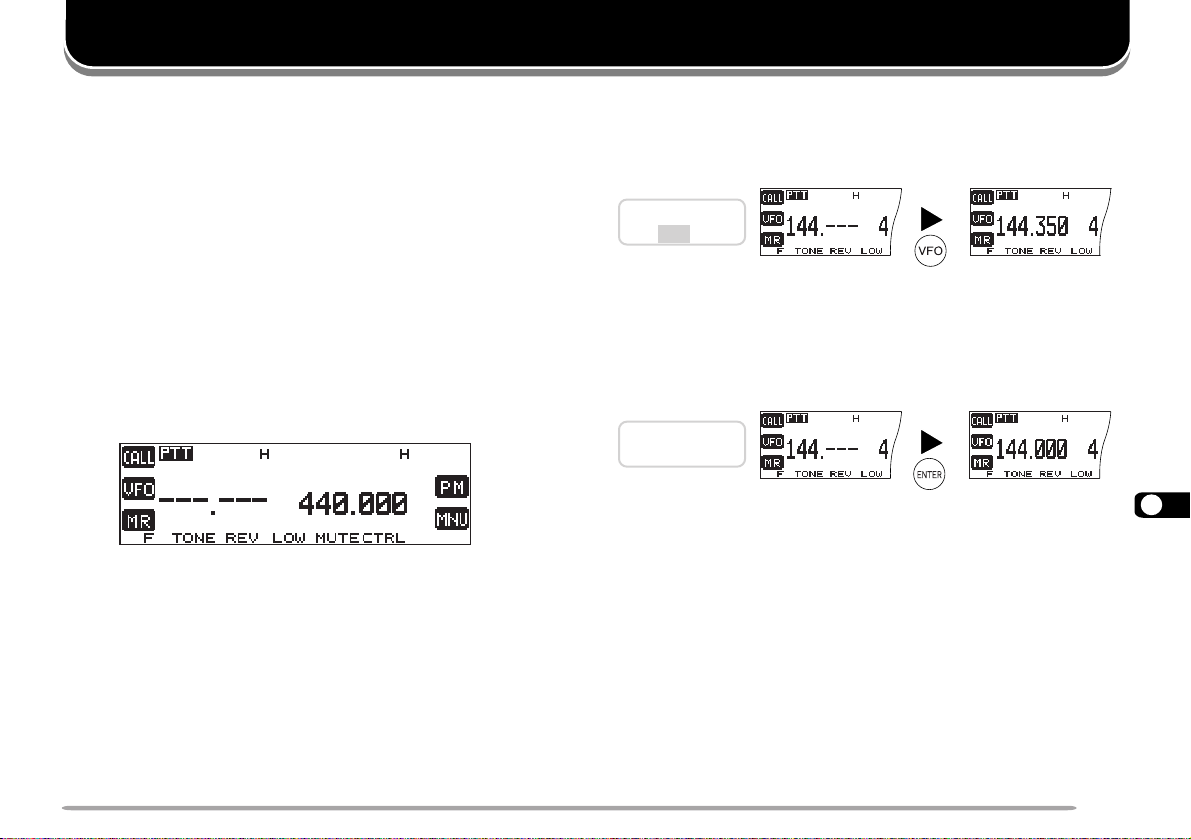
AUXILIARY FUNCTIONS
DIRECT FREQUENCY ENTRY (WITH MC-53DM ONLY)
If the desired operating frequency is far from the current
frequency, using the Mic keypad is the quickest way to
change frequency. First program one of the Mic PF keys
as the ENTER key {page 62},
1 Press the left or right [BAND SEL] to select band A or
B.
• If necessary, press [F], then the same [BAND SEL] to
recall the sub-band.
2 Press [VFO].
3 Press Mic [ENTER].
• The display for Direct Frequency Entry appears.
4 Press the numeric keys in sequence on the keypad.
Note:
◆
The 1 kHz and subsequent digits are corrected according to which
key is pressed for the 1 kHz digit.
◆
Entering a digit that is outside the allowable range causes the nearest
digit within range to be displayed.
◆
You cannot enter a frequency in a band which cannot be recalled on
the current band.
If you press Mic [VFO] while entering a frequency, the
new data is accepted for the digits entered and the
previous data remains unchanged for the digits not yet
entered.
Previous freq.:
145.350 MHz
Note: The 1 kHz and subsequent digits may be corrected depending on
combinations of the previous frequency and the current frequency step
size.
If you press Mic [ENTER] while entering a frequency, the
new data is accepted for the digits entered and 0 is
programmed for the digits not yet entered.
Previous freq.:
145.350 MHz
14
63
Page 70
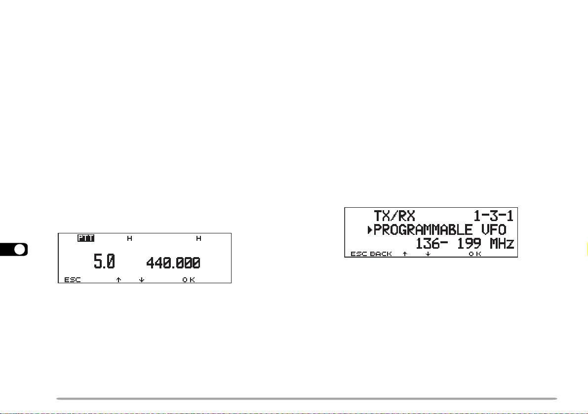
CHANGING FREQUENCY STEP SIZE
PROGRAMMABLE VFO
Choosing the correct step size is essential in order to
select your exact frequency using the Tuning control or
Mic [UP]/ [DWN]. The default step size on the 144 MHz
band is 5 kHz (U.S.A./ Canada) or 12.5 kHz. The
default on the 440/430 MHz band is 25 kHz no matter
which market version. For the U.S.A./ Canada version,
the default on the 118, 220, or 300 MHz band is 12.5
kHz and the default on the 1.2 GHz band is 25 kHz.
1 Press the left or right [BAND SEL] to select band A or
B.
• If necessary, press [F], then the same [BAND SEL] to
recall the sub-band.
2 Press [VFO].
3 Press [F], [STEP].
• The current step size appears and blinks.
14
cc
4 Press [
• The selectable step sizes are 5, 6.25, 10, 12.5, 15, 20,
25, 30, 50, and 100 kHz.
dd
c]/ [
d] to select the desired step size.
cc
dd
5 Press [OK] to complete the setting.
Note: Changing between step sizes may correct the displayed
frequency. For example, if 144.995 MHz is displayed with a 5 kHz step
size selected, changing to a 12.5 kHz step size corrects the displayed
frequency to 144.9875 MHz.
64
If you always check frequencies within a certain range,
set upper and lower limits for frequencies that are
selectable using the T uning control or Mic [UP]/
[DWN]. For example, if you select 145 MHz for the
lower limit and 146 MHz for the upper limit, the tunable
range will be from 145.000 MHz to 146.995 MHz.
1 Press the left or right [BAND SEL] to select band A
or B, then press [VFO].
• If necessary, press [F], then the same [BAND SEL]
to recall the sub-band.
2 Press [MNU], select Menu 1–3–1
(PROGRAMMABLE VFO), then press [OK].
• The current lower frequency limit blinks.
cc
3 Press [
dd
c]/ [
d] to select the desired lower
cc
dd
frequency limit, then press [OK].
• The current upper frequency limit blinks.
cc
4 Press [
dd
c]/ [
d] to select the desired upper
cc
dd
frequency limit, then press [OK].
5 Press [MNU] to exit Menu mode.
Note:
◆
You cannot program the 100 kHz and subsequent digits.
◆
The exact 100 kHz and subsequent digits of the upper limit
depend on the frequency step size selected.
Page 71
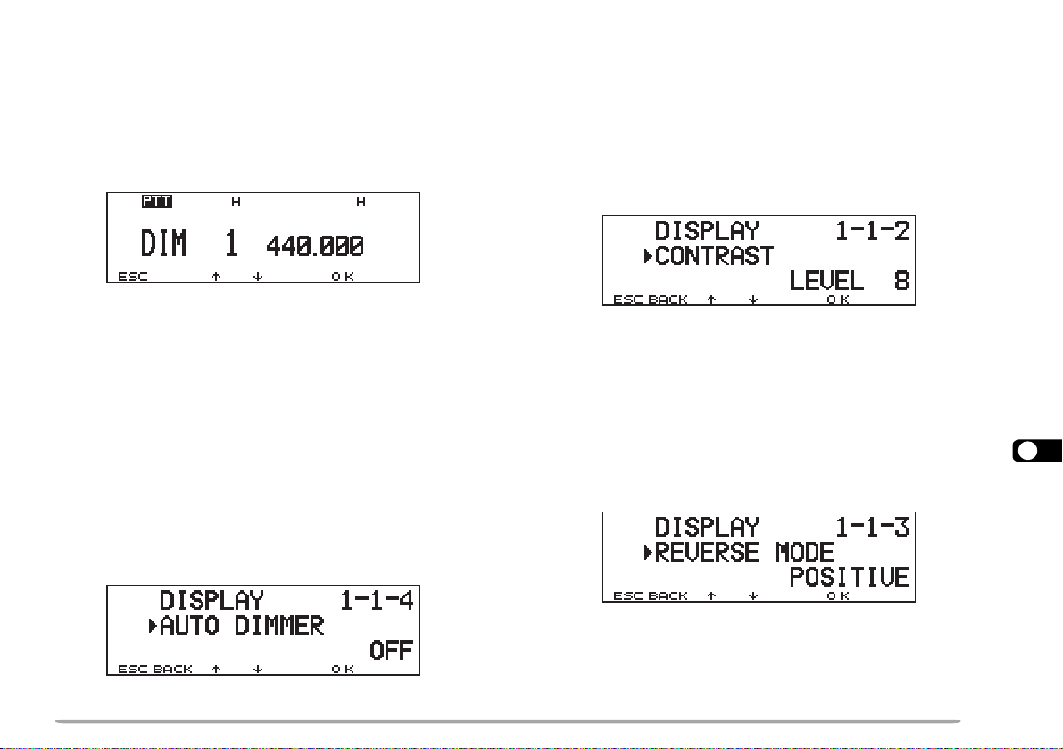
DISPLAY DIMMER
DISPLAY CONTRAST ADJUST
You can manually change the display illumination to suit
the lighting conditions where you are operating.
1 Press [F], [DIM].
• The current illumination level appears and blinks; The
default is level 1.
cc
2 Press [
3 Press [OK] to complete the setting.
Note: Selecting OFF automatically switches Auto Dimmer Change ON.
dd
c]/ [
d] to select from 5 levels, including OFF.
cc
dd
AUTO DIMMER CHANGE
This function increases the display intensity one step
brighter for approximately 5 seconds when you press a
front panel button or Mic key, or turn the Tuning control.
No change occurs if you have selected the brightest
level. Access Menu 1–1–4 (AUTO DIMMER) and select
“ON”.
The display visibility changes depending on ambient
conditions, for example between daytime and nighttime.
When you find the display is not clear, use this function
to select the optimum display contrast.
Access Menu 1–1–2 (CONTRAST) and select from
levels 1 to 16. The default is level 8.
Note: The display contrast may be affected by a change in temperature.
Adjust the contrast as necessary.
POSITIVE/ NEGATIVE REVERSAL
You can change the display status between Negative
and Positive (default) using Menu 1–1–3 (REVERSE
MODE).
14
65
Page 72

BLANKING A BAND DISPLAY
AUTOMATIC BAND CHANGE (A.B.C.)
If you have no plans to use band A or B, quit frequency
display on the unused band. This saves power
consumption and makes it simpler to read the
information you need.
Press the left [BAND SEL] (1 s) to blank band B, or the
right [BAND SEL] (1 s) to blank band A.
To restore Dual-band mode, press the same [BAND
SEL] (1 s).
Note: You cannot operate the blanked band nor use this band to receive
or transmit.
14
A.B.C. will temporarily switch the RX only band to the TX
band immediately after a signal is received on the RX
only band. This function allows you to reply to a caller
without manually selecting the correct band.
Press [F], [A.B.C] to switch the function ON (or OFF).
• “A.B.C.” appears when the function is ON.
• Pressing [BAND SEL] or Mic [PTT] also cancels A.B.C.
• The original TX band is restored 2 seconds after signals
drop out.
Note:
◆
You cannot use A.B.C. when in Single-band mode. After activating
A.B.C., changing from Dual-band mode to Single-band mode
switches OFF the A.B.C.
◆
After activating A.B.C., starting Visual Scan deactivates A.B.C.
Canceling Visual Scan reactivates A.B.C.
66
Page 73

TRANSCEIVER LOCK
1edoM
]YEK[ ENOTVERWOLETUMLRTC
]YEK[,]F[ LES.TTFIHSPETS
LAUSIV
MID
]YEK[,)s1(]F[ TSILNOM.PNOCBGSMSOP
2edoM
]YEK[ LES.TTFIHSPETS
LAUSIV
MID
]YEK[,]F[ TSILNOM.PNOCBGSMSOP
]YEK[,)s1(]F[ ENOTVERWOLETUMLRTC
3edoM
]YEK[ TSILNOM.PNOCBGSMSOP
]YEK[,]F[ ENOTVERWOLETUMLRTC
]YEK[,)s1(]F[ LES.TTFIHSPETS
LAUSIV
MID
CHANGING MULTI-FUNCTION BUTTON LABELS
Transceiver Lock is suitable for a typical mobile
installation where you alter most functions with your
microphone. This Lock disables all functions excluding
the following:
RWP hctiws ]F[]F[ , ]zHM[
LQS slortnoc LOV slortnocsyekciM
Press [F], [MHz] to switch the function ON (or OFF).
• “LOCK” appears when the function is ON.
ALL-CONTROL LOCK
All-control Lock is ideal when you have no plans to
transmit but you want to monitor a specific frequency.
This Lock disables all functions excluding power ON/
OFF and All-control Lock ON/OFF.
After switching Transceiver Lock ON, switch OFF the
transceiver, then press [MHz]+ POWER ON to switch
the function ON (or OFF).
• “ALL LOCK” appears when the function is ON.
The functions to be frequently used may differ among
persons. You can change the defaults of the 5 buttons
located below the display.
Access Menu 1–1–5 (KEY FUNC) and select mode 1
(default), 2, or 3.
14
67
Page 74

S-METER SQUELCH
S-meter Squelch causes the squelch to open only when
a signal with the same or greater strength than the Smeter setting is received. This function relieves you from
constantly resetting the squelch when receiving weak
stations that you have no interest in.
1 Select the desired band.
2 Press [MNU] to enter Menu mode.
3 Select 1–3–2 (S-METER SQUELCH), then press
[OK].
cc
4 Press [
14
5 Press [OK] to complete the setting.
6 Press [MNU] to exit Menu mode.
• The S-meter setting segments appear.
dd
c]/ [
d] to switch the function ON (or OFF).
cc
dd
7 To select the desired S-meter setting, turn the left
(band A) or right (band B) SQL control depending on
which band you selected.
■ Squelch Hang Time
When using S-meter Squelch, you may want to adjust
the time interval between when the received signals
drop and when the squelch closes.
Access Menu 1–3–3 (SQUELCH HANG TIME) and
select from OFF (default), 125, 250, and 500 msec.
68
Page 75
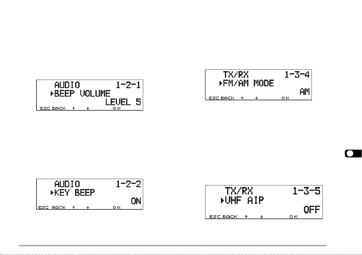
CHANGING BEEP VOLUME
SWITCHING FM/AM MODE
The transceiver beeps each time you press a front panel
button or Mic key, or when it receives appropriate APRS
or DX cluster data. You can change the beep volume or
turn it off.
Access Menu 1–2–1 (BEEP VOLUME) and select the
volume from levels 1 to 7 and OFF. The default is level
5.
KEY BEEP ON/ OFF
If you are distracted by beeps generated when pressing
a front panel button or Mic key, switch OFF the Key
Beep. The transceiver will beep only when it receives
appropriate APRS or DX cluster data.
Access Menu 1–2–2 (KEY BEEP) and select “OFF”.
This transceiver is also capable of receiving (not
transmitting) in AM on band A. The default mode on the
118 MHz band is AM while the default on the 144, 220,
300, or 440 MHz band is FM. After recalling the desired
band on band A, access Menu 1–3–4 (FM/AM MODE)
and switch between FM and AM.
• The 1 MHz decimal becomes elongated when AM is
selected.
Note: You cannot switch between FM and AM to receive on band B.
ADVANCED INTERCEPT POINT (AIP)
The VHF band is often crowded in urban areas. AIP
helps eliminate interference and reduce audio distortion
caused by intermodulation. You may use this function
when operating on the VHF band. Access Menu 1–3–5
(VHF AIP) and select “ON”.
14
Note: After selecting OFF, you will still hear TOT and APO alarms.
Note:
◆
This transceiver does not allow you to use the AIP on the UHF band.
◆
Switching ON the AIP also affects the VHF sub-band on band B.
69
Page 76
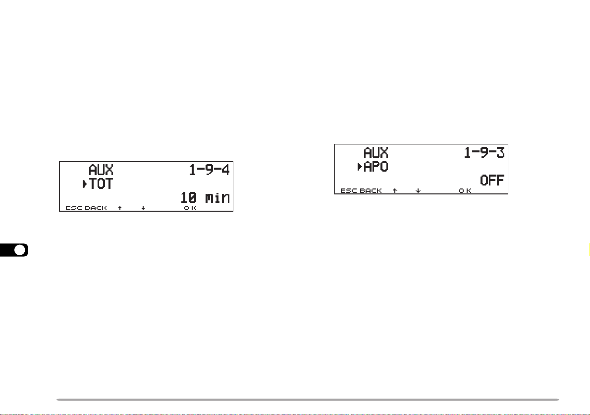
TIME-OUT TIMER (TOT)
AUTOMATIC POWER OFF (APO)
It is sometimes necessary or desirable to restrict a single
transmission to a specific maximum time. You may use
this function to prevent repeater time-outs when
accessing repeaters, or to conserve battery power.
When TOT times out, the transceiver generates beeps
and automatically returns to receive mode. To resume
transmitting, release and then press Mic [PTT] again.
Access Menu 1–9–4 (TOT) and select 3, 5, or 10
(default) minutes for the TOT time.
14
Automatic Power Off is a background function that
monitors whether any buttons or keys have been
pressed, or whether the Tuning control has been turned.
After 3 hours pass with no operations, APO turns OFF
the power. However, 1 minute before the power turns
OFF, “APO” appears and blinks, and a series of warning
tones sound.
Access Menu 1–9–3 (APO) and select “ON”.
Note: If any settings are changed during the 3 hour period while APO is
ON, the timer resets. When you stop changing the settings, the timer
begins counting again from 0.
70
Page 77
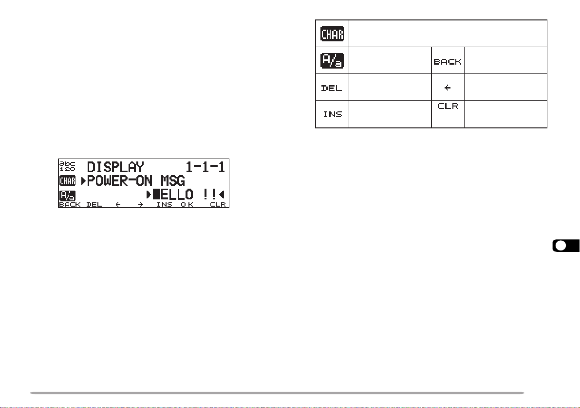
POWER-ON MESSAGE
Each time you switch the transceiver ON, “HELLO !!”
appears and stays for approximately 2 seconds. You
can program your favorite message in place of the
factory default.
1 Press [MNU] to enter Menu mode.
2 Select Menu 1–1–1 (POWER-ON MSG), then press
[OK].
• The display for entering a message appears; the first
digit blinks.
ciremunahplafostesehtgnomasehctiwS
.sretcarahcIICSAlaicepsdna
neewtebsehctiwS
.srettel
.gniknilb
latipacdnallams
tatigidehtseteleD
sirosrucehthcihw
yltnerrucehtstresnI
.retcarahcdetceles
)LES
.yrtnE
DNABtfel(
,)ylnoE007D-MT(sretteldetnecca,sretcarahc
egasseMslecnaC
.tigidtsrifeht
6 Press [OK] to complete the setting.
7 Press [MNU] to exit Menu mode.
The keypad on the MC-53DM also is available to enter
alphanumeric characters in step 3. See page 18.
rosrucehtsesuaC
.drawkcabevomot
dnastigidllasraelC
otrosrucehtskcab
3 Turn the Tuning control to select a character.
• You can enter alphanumeric characters plus special
ASCII characters.
4 Press [
• The cursor moves to the next digit.
aa
a].
aa
5 Repeat steps 3 and 4 to enter up to 8 digits.
DISPLAY DEMONSTRATION
By initiating this function, various preprogrammed
displays appear. You still can normally use the
transceiver in this mode. Pressing a front panel button
or Mic key, or turning the Tuning control restores the
operating display immediately. If there is no button/key
entry or Tuning control adjustment for approximately
10 seconds, the transceiver reverts back to
Demonstration mode.
Press [F]+ POWER ON to switch the function ON (or
OFF).
14
71
Page 78
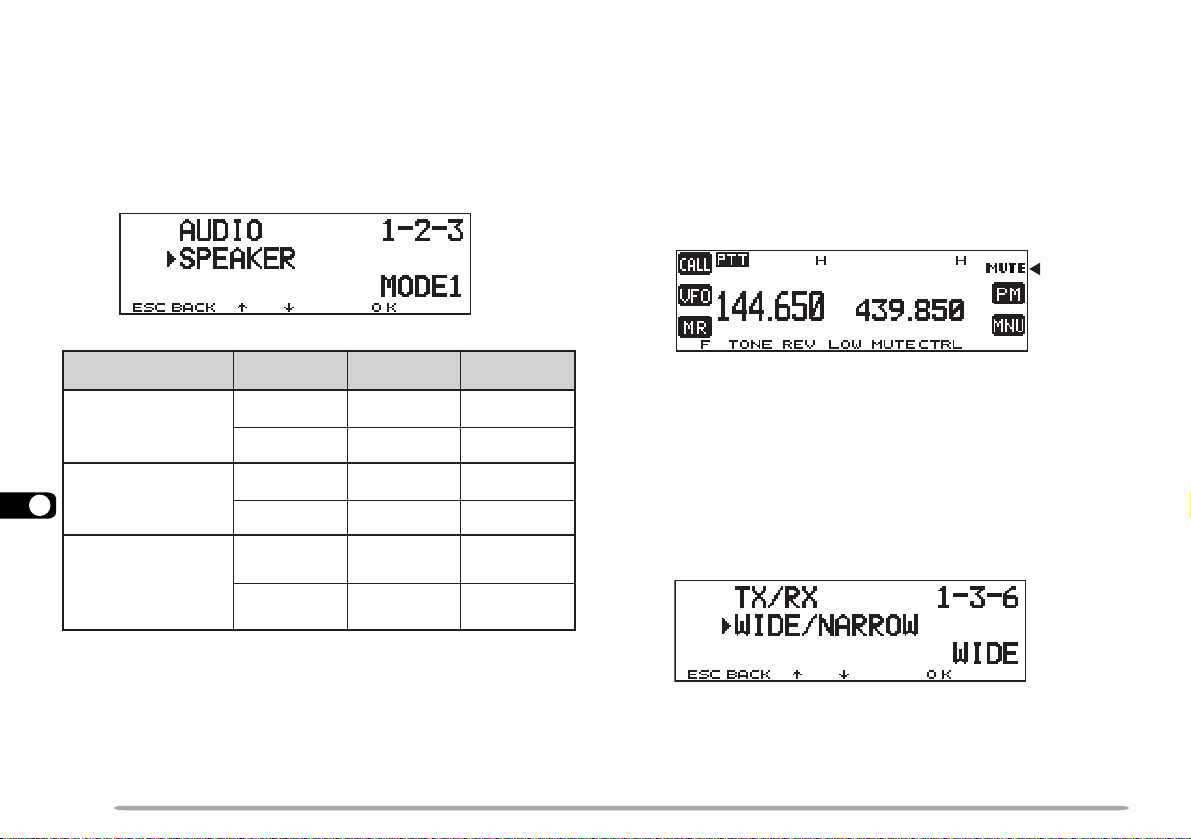
CHANGING SPEAKER CONFIGURATIONS
SPEAKER MUTE
This transceiver has two speaker jacks. You can enjoy a
variety of speaker configurations by using one or two
external speakers. Access Menu 1–2–3 (SPEAKER)
and select mode 1 (default) or 2, depending on how the
internal and/or external speakers should function.
noitcennoC edoM AdnaB BdnaB
14
kcaj1PSylnO
nahtiwdetcennoc
rekaepslanretxe
kcaj2PSylnO
nahtiwdetcennoc
rekaepslanretxe
2PSdna1PShtoB
detcennocskcaj
lanretxehtiw
srekaeps
1edoMlanretxElanretxE
2edoMlanretxElanretxE
1edoMlanretxElanretnI
2edoMlanretnIlanretxE
1edoM2lanretxE1lanretxE
2edoM1lanretxE2lanretxE
While receiving or transmitting on the TX band, you may
not want to hear audio received on the other band. Use
this function to mute the speaker allocated to that band
(not TX band).
Press [MUTE] to switch the function ON (or OFF).
• “MUTE” appears when the function is ON.
CHANGING TX/RX DEVIATION (TM-D700E ONLY)
This transceiver is capable of switching between wide
and narrow deviations to receive or transmit. After
selecting the desired band, access Menu 1–3–6 (WIDE/
NARROW) and switch between Wide (default) and
Narrow.
72
• When Narrow is selected, “N” appears beside the
frequency.
Note: Do not select Narrow for the band configured as a data band. The
selection of Narrow is invalid on the data band.
Page 79

2
/ycneuqerF)SSCTCro(enoT
tceleSedoCSCD
1
8tceleSdnab-buS
3tceleSnoitceriDtesffO D
edoMnoitcnuf-itluM
lecnaC
5kcoLdapyeKFMTD nwoD
6kcolnUdapyeKFMTD
#
pU
7tceleSB/AdnaB
MICROPHONE CONTROL (WITH MC-53DM ONLY)
You can change numerous transceiver settings by
operating the Mic DTMF keys. To activate this function,
access Menu 1–8–5 (MIC CONTROL) and select “ON”.
The following table shows what function is switched ON
and OFF or which setting is changed, by pressing the
DTMF keys.
1nacSlausiV 9tnemtsujdAhcleuqS
2SCD/SSCTC/enoT 0egnahCrewoPXT
3esreveR AretnE
4egnahCpetSzHM1 BtceleSdnaBlortnoC
5rotinoM CretaepeR
6
1
speeByb
7egnahCemuloV
8etuMrekaepS
1
The transceiver announces the displayed information if you
have installed an optional VS-3 unit and selected “English” in
Menu 1–2–4 (VOICE) {page 83}.
2
After entering the selection mode, press [ ] or [#] to
change the level or selection.
3
Both Volume Change and Squelch Adjustment cannot be
activated at the same time.
4
Both Volume Change and Squelch Adjustment must be OFF
to change the tone or frequency step using this key.
tuodaeRycneuqerF
3,2
D ]F[ yek
pU
#
4
nwoD
4
You can also make the following settings by pressing [D]
first (ex. [D], then [2]).
1
After entering the selection mode, press [ ] or [#] to
change the level or selection.
3,2
Before pressing [D], [2], press [2] to activate the Tone,
CTCSS, or DCS function.
Press [OK] on the front panel of the transceiver to complete
the setting.
Note: Audible DTMF tones from other transceivers near you may be
picked up by your MC-53DM microphone. If so, this could prevent the
function from working correctly.
15
73
Page 80

WIRELESS REMOTE CONTROL (U.S.A./ CANADA ONLY)
If you also have a compatible KENWOOD handy
transceiver, you may use it as a remote control for this
mobile transceiver. You will control one band on the
mobile while sending DTMF tones to the other band from
the handheld. This function will be useful, for example,
when you want to control the mobile from a location
outside your vehicle.
Note:
◆
As a remote control, you can also use a handy transceiver which
does not have a remote control function but a DTMF function. Y ou,
however, must manually send DTMF tones for control code strings.
Skip steps 1 and 3 in “PREPARATION”.
◆
The FCC rules permit you to send control codes only on the 440 MHz
band.
DTMF tones
16
PREPARATION
Let us assume band A (VHF) of the mobile transceiver
will be controlled.
On the handy transceiver:
1 Program a 3-digit secret number.
• For the programming method, see the instruction
manual for the handheld.
• If using a TH-D7A, see “WIRELESS REMOTE
CONTROL” on its instruction manual.
2 Select the transmit frequency on the UHF band.
3 Make the handheld enter Remote Control mode.
• For the method, see the instruction manual for the
handheld. If not described, consult your dealer.
On the mobile transceiver:
4 Access Menu 1–A–1 (CODE), and select the same
secret number as you selected in step 1.
74
• Turn the Tuning control to select each digit. Press [
bb
(or [
b]) to move the cursor to the next (or previous)
bb
digit.
• You can also press Mic [0] to [9] in sequence to enter 3
digits.
aa
a]
aa
Page 81
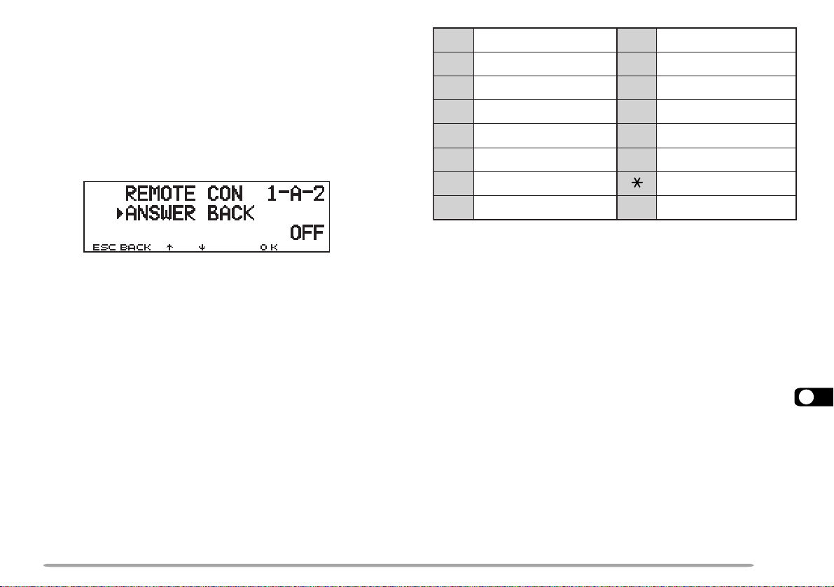
5 Select the receive frequency on band B (UHF).
1NOVER 9RM
2NOENOT 0WOL
3NOSSCTC ARETNE
4FFOVER BLESENOT
5FFOENOT CNORETAEPER
6FFOSSCTC DFFORETAEPER
7LLAC NWOD
8OFV
#
PU
• Mate this frequency with the transmit frequency on the
handheld.
6 Select band A (VHF) as the TX band or Control band
{page 17}.
7 To cause the mobile to send a control acknowledgment
to the handheld, access Menu 1–A–2 (ANSWER
BACK) and select “ON”.
• DTMF tones which represent the secret number will be
used as an acknowledgment.
8 Access Menu 1–A–3 (CONTROL) and select “ON”.
• “REMOTE CON” and “LOCK” appear when the mobile
enters Remote Control mode.
CONTROL OPERATION
When in Remote Control mode, the DTMF keys of the
handheld will function as shown in the table. Each time
you press the desired key, the handheld will
automatically enter transmit mode and send the
corresponding command to the mobile.
Note: If using a handheld without a remote control function, manually
send “AXXX#YA#” where “XXX” is a 3-digit secret number and “Y” is a
single-digit control command. If you do not add ”A#” to the end, you can
skip sending “AXXX#” next time; however, the mobile may be accidentally
controlled by other stations.
To change the transmit/ receive frequency:
([VFO] ➡ [ENTER] ➡ [0] ~ [9] (enter the necessary
digits) ➡ [ENTER]) or ([VFO] ➡ [UP]/ [DOWN])
To recall a memory channel:
([MR] ➡ [ENTER] ➡ [0] ~ [9] (enter the necessary
digits) ➡ [ENTER]) or ([MR] ➡ [UP]/ [DOWN])
To change the tone (or CTCSS) frequency:
([TONE SEL] ➡ [0] ~ [9] (enter 2 digits; ex. [0], [5]) ➡
[TONE SEL])
• Use Nos. 01 to 38 shown in the table in page 30.
• First activate the Tone or CTCSS function. You can select a
separate tone frequency for the Tone and CTCSS functions.
Note: When in Remote Control mode, you can perform only the following
operations on the mobile transceiver.
•
Transmit
•
Secret Number Change
•
Answer Back ON/ OFF
•
Partial/ Full Reset (with RESET button)
75
16
Page 82

SKY COMMAND
PF
ATT PRE-AMP
VOX PROC
SEND
CH1
MIC
CW
FSK
LSB
USB
FM
AM
AT TUNE
POWER
HF TRANSCEIVER TS-570D
PHONES
1
CH22CH3
3
ANT4REC5FINE
6
NB7AGC/TONE8REV
9
CLR
F.LOCK
0
ENT
MIC
PWR
KEY
DELAYMENU 1MHz
SPLIT
M/V
DOWN
UP
MR
TF-SET
A=B
SCAN M>VFO M.IN
M.IN
FILTER
CW TUNE
B.C.
N.R.
A/B
CLEAR
RIT
XIT
RIT/XIT
IF SHIFT SQL
CH
46
010
28
AF RF
L
O
W
C
U
T
HIGH
DSP SLOPE
LOW
46
010
28
+–
VHF freq.
Commander Transporter
Audio
Audio
UHF freq.
Audios
Control commands
tResponse
Control commands
tResponse
22
2 (U.S.A./ CANADA ONLY)
22
The Sky Command 2 allows remote control of a
TS-570D, TS-570S, or TS-870S HF transceiver. Besides
the HF transceiver, this system requires two transceivers
capable of working the Sky Command 2. This
transceiver and TH-D7A handhelds are currently
available. You will use one transceiver as a control
station called “Commander”. The transceiver connected
with the HF transceiver is called “Transporter”. It will
function as an interface between the Commander and
the HF transceiver. This system allows you, for
example, to watch for and hunt DX while washing your
car, or to operate the HF transceiver while relaxing in
your car, living room, or patio, instead of in your shack.
HF freq.
17
76
UHF freq.
Your shack
VHF freq.
The Commander and Transporter transfer audio and
commands as below:
Page 83
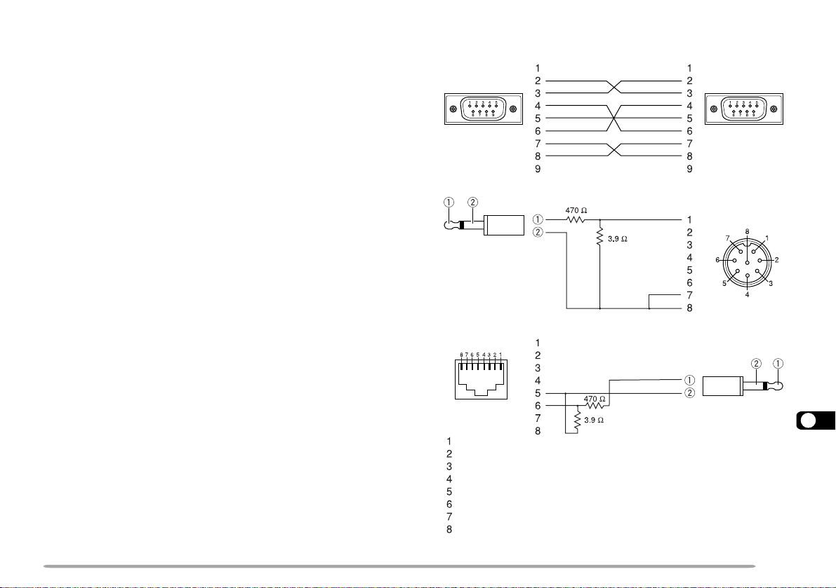
CONNECTING THE TRANSPORTER WITH THE HF
TRANSCEIVER
In order to connect the transporter to the HF transceiver,
you need to prepare three cables by yourself. For the
connection between the COM connectors on the two
transceivers, you may use a commercially available RS232-C cross-wired cable.
Note:
◆
Switch OFF both the Transporter and HF transceiver before making
the connection.
◆
The Transporter automatically transmits its call sign in Morse at
regular intervals because of legal requirements; therefore, transmit
sidetone must be output from the HF transceiver. On TS-570D or
TS-570S, do not select “OFF” in Menu 21. On TS-870S, use the
MONI control to adjust the sidetone volume.
◆
When the Transporter is too close to the HF transceiver, unwanted
feedback may cause malfunction.
◆
Do not share a regulated power supply between the Transporter and
the HF transceiver. Unwanted feedback may cause malfunction.
TM-D700A
COM connector
on TM-D700A
To 3.5 mm (1/8")
speaker jack
HF transceiver
COM connector
on HF transceiver
MIC connector
on HF transceiver
MIC connector
on TM-D700A
UP
8 V DC
GND
STBY (PTT)
GND (MIC)
MIC
NC
DWN
To EXT SP jack
17
77
Page 84

PREPARATION FLOW
The following steps should guide you to a good start of
Sky Command operation. First connect the Transporter
to the HF transceiver {page 77}.
q On the Commander
and Transporter
w On the Commander
e On the Commander
17
r On the Transporter
t On the Transporter
78
Select the same VHF and UHF
frequencies.
Access Menu 4–1 to program
a call sign (9 digits max.) for
the Commander {page 79}.
• You may enter your exact call
sign; ex. WD6BQD.
Access Menu 4–2 to program
a call sign (9 digits max.) for
the Transporter {page 79}.
• This call sign must be different
from the one for the
Commander. So you may add
SSID characters; ex.
WD6BQD-1.
Access Menu 4–1 to program
the same call sign as you
entered in step w {page 79}.
Access Menu 4–2 to program
the same call sign as you
entered in step e {page 79}.
y On the Commander
and Transporter
u On the Commander
Access Menu 4–3 and select
the tone frequency {page 79}.
• Select the same tone frequency
on both transceivers.
• For the selectable frequencies,
see the table given on page 30.
Access Menu 4–4 and select
“COMMANDER”.
• “PUSH [ 0 ] KEY TO START
COMMANDER!!” appears.
i On the Transporter
Access Menu 4–4 and select
“TRANSPORTER”.
Now the Commander and Transporter are in Sky
Command mode. For operations in this mode, see
“CONTROL OPERATION” on page 80. First switch ON
the HF transceiver and press [SYNC] on the
Commander. To exit the Sky Command mode, access
Menu 4–4 and select “OFF”.
Note:
◆
Unless you program call signs, you cannot select “COMMANDER” or
“TRANSPORTER” using Menu 4–4.
◆
On the HF transceiver, select 9600 bps and 1 stop bit (default) using
the Menu Set-up function.
◆
Adjust the audio level on both the Transporter and HF transceiver
while listening to audio output from the Commander. An appropriate
position of the AF control on the HF transceiver might be in the range,
8:30 to 9:00.
◆
To distinguish your various stations or nodes, you can have up to 15
Secondary Station IDentifiers (SSIDs); ex. WD6BQD-1 to WD6BQD-
15. You always have to put a dash between your call sign and SSID
number.
Page 85

PROGRAMMING CALL SIGNS
The built-in TNCs of the Commander and Transporter
communicate each other when you send a control
command from the Commander. So you must program
different call signs (9 digits max.) on these transceivers
as the IDs of the TNCs.
Use the following Menu Nos. to program call signs:
4 Press [
• The cursor moves to the next digit.
aa
a].
aa
5 Repeat steps 3 and 4 to enter up to 9 digits.
.ngisllac
afoyrtneslecnaC
.gniknilb
rosrucehtsesuaC
.drawkcabevomot
tatigidehtseteleD
sirosrucehthcihw
yltnerrucehtstresnI
.retcarahcdetceles
rednammoCnO
1–4NGISLLACDMCrednammoCrofngisllaC
2–4NGISLLACPRTretropsnarTrofngisllaC
retropsnarTnO
1–4NGISLLACDMCrednammoCrofngisllaC
2–4NGISLLACPRTretropsnarTrofngisllaC
1 Press [MENU] to enter Menu mode.
2 Select “4–1 (CMD CALLSIGN)” or “4–2 (TRP
CALLSIGN)”, then press [OK].
• The callsign entry field appears; the first digit blinks.
3 Turn the Tuning control to select a character.
• You can enter 0 to 9, A to Z, and –.
.tigid
tsrifehtotrosrucehtskcabdnastigidllasraelC
6 Press [OK] to complete the setting.
7 Press [MENU] to exit Menu mode.
The keypad on the MC-53DM also is available to enter
alphanumeric characters in step 3. See page 18.
PROGRAMMING A TONE FREQUENCY
On receiving a tone from the Commander, the
Transporter causes the HF transceiver to enter Transmit
mode. On both the Commander and Transporter,
access Menu 4–3 (TONE FREQUENCY) and select the
desired, same tone frequency.
17
79
Page 86

CONTROL OPERATION
yeKciM noitcnuF
1 FFO/NOrewoP
2 FFO/NOeviecerycneuqerfFH
3 hctiwsedomnoitaludoM
4 FFO/NOTIR
5 FFO/NOTIX
6 raelctesffoTIXrotesffoTIR
7 FFO/NOycneuqerf-tilpS
8 OFVotyromeMmorfrefsnarT
9
hctiwsBOFV/AOFV:edomOFVnI
egnahcon:edomllaceRyromeMnI
0
FHmorf(eveirtersgnittestnerruC
)reviecsnart
B hctiwsedomllaceRyromeM/OFV
C esaercniycneuqerftesffoTIR/TIX
D esaercedycneuqerftesffoTIR/TIX
1
zHk1/zH01:edomWCro,BSU,BSLnI
hctiws
hctiwszHk01/zHk1:edomMAroMFnI
#
2
NOyrtneycneuqerf:edomOFVnI
rebmunlennahc:edomllaceRyromeMnI
NOyrtne
When in the Sky Command mode, the Mic keys of the
Commander will function as below. First switch ON the
HF transceiver and press Mic [0] on the Commander.
Each time you press the desired key, the Commander
will automatically enter transmit mode and send the
corresponding control command to the Transporter.
17
80
FHehtFFO/NOhctiwsoT
reviecsnart
roycneuqerfehtegnahcoT
reviecsnart
FHehtnolennahcyromem
FHnanooiduatimsnartoT
ycneuqerf
FHnanooiduaevieceroT
ycneuqerf
dnabFHUehtrotinomoT
rednammoCehtno
ciMsserP ]1[ .
ciMsserP ]PU[ / ]NWD[ .
.enohporcim
ciMsserP ]2[ .
.noitcnuf
ciMdlohdnasserP ]TTP[ ,
ehtotnikaepsneht
yekFPciMehtsserP
rotinoMehtdengissa
1
“FS” appears when you select 1 kHz step (LSB/ USB/ CW) or
10 kHz step (FM/ AM).
2
After pressing Mic [#], press Mic [0] to [9] to enter a
frequency or memory channel number.
Page 87
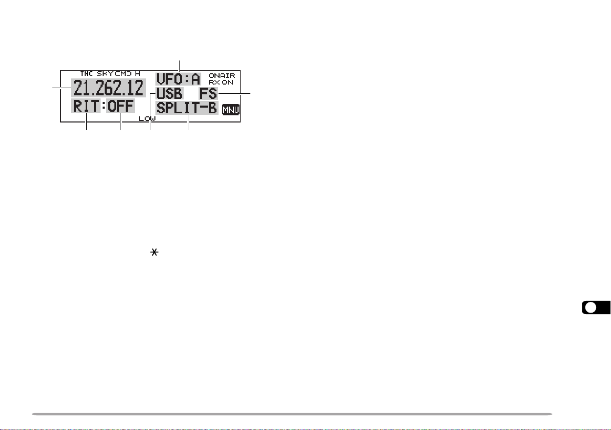
When Mic [0] is pressed, the Commander shows the
current settings of the HF transceiver as below:
w
q
eyr
t
u
q HF frequency
w VFO: A, VFO: B,
MR: 00 ~ 99 (memory channel number)
e RIT, XIT
r OFF, –9.99 ~ +9.99
t LSB, USB, CW, FM, or AM
y SPLIT–A: VFO A is used for transmitting.
SPLIT–B: VFO B is used for transmitting.
SPLIT–M: A memory channel is used for transmitting.
u “FS” appears when Mic [
Note:
◆
After pressing [MENU], you can access only Menu 4–4.
◆
The Transporter will transmit its call sign in Morse every 10 minutes,
using the 144 MHz band.
◆
The APO timer does not operate on the transceiver with Transporter
ON.
] is pressed.
17
81
Page 88

REPEATER FUNCTION (U.S.A./ CANADA ONLY)
This transceiver is capable of receiving signals on one
band and retransmitting signals on the other band. This
function repeats signals originating from one band, using
the other band. For example, a signal received on band
A (VHF) is retransmitted on band B (UHF). Similarly, a
signal received on band B (UHF) is retransmitted on
band A (VHF).
Access Menu 1–7–6 (REPEATER) and select Lockedband Repeater or Cross-band Repeater. The default is
“OFF”.
Cross-band
Repeater
• “PTT” blinks when in the Locked-band or Cross-band
Repeater mode.
Locked-band Repeater
The transceiver always uses the same band to receive
or transmit a signal as a repeater. Before accessing
Menu 1–7–6, select one band as the TX band and the
18
other band as the control band.
Cross-band Repeater
If receiving a signal on the TX band, the transceiver
switches the current RX only band to the TX band.
Before accessing Menu 1–7–6, select the same band as
the TX and control bands.
If necessary, you can cause this transceiver to remain in
the transmit mode for 500 ms after signals drop. Access
Menu 1–7–5 (REPEATER HOLD) and select “ON”.
Note:
◆
You cannot activate the Repeater function after recalling the same
frequency band (VHF or UHF) on band A and B, or while blanking a
band display.
◆
Activating the Repeater function switches OFF Automatic Band
Change (A.B.C.) or Automatic Simplex Check (ASC).
◆
The Time-Out Timer is locked at 3 minutes.
◆
After activating the Repeater function, you cannot access Menu Nos.
other than 1–7–5 and 1–7–6.
82
Page 89

VS-3 VOICE SYNTHESIZER (OPTIONAL)
OFV
dnabtnerrucehtnoycneuqerfOFV
tigidzHM001ehthtiwgninnigeb
)”tniop“:tnioplamicedzHM(
llaceRyromeM
ehtdna,”lennahc“,rebmunlennahC
ycneuqerf
,”pu“ro”wol“,slennahcUroLehtroF
ycneuqerfehtdna,rebmunlennahceht
yalpsiDlennahC
.”lennahc“dnarebmunlennahC
”pu“ro”wol“,slennahcUroLehtroF
rebmunlennahcehtdna
lennahCllaC
llaceR
ycneuqerfehtdna”llaC“
uneM
)ylnoyekecioVhtiw(rebmumuneM
SSCTC,.qerfenoT
edocSCD,qerf
tceles
SCDro,qerfSSCTC,.qerfenoTtnerruC
edoc
Install the optional VS-3 unit to use this function
{page 85}. Each time you change the transceiver mode,
such as VFO or Memory Recall, the transceiver
automatically announces the new mode. In order to use
the installed VS-3 unit, access Menu 1–2–4 (VOICE) and
select “English”. The default is OFF. For “APRS ONLY”
selectable in this menu number, see the separate manual,
“SPECIALIZED COMMUNICATIONS” {page 28}.
The table below shows what the transceiver
automatically announces when it enters a new mode.
desserPyeK edoMweN tnemecnuonnA
]OFV[ OFV”OFV“
]RM[ llaceRyromeM”RM“
]LLAC[ lennahCllaC”llaC“
]MP[
]UNM[ uneM
yekFPciM
}26egap{
1
When pressed in Memory Recall mode, the transceiver
announces “A” or “B”, the channel number, “channel”, the
frequency, and the TX power. When in Call channel mode,
the transceiver announces “A” or “B”, “call”, the frequency,
and the TX power..
2
When pressed in VFO or Memory Recall mode.
]LESDNAB[
retnEhtiwdemmargorp
2
elbammargorP
yromeM
lortnoC/XTweN
dnab
tceriDdapyeK
yrtnE
You can also press Mic [6] in Microphone Control mode
{page 73} or the PF key programmed with Voice {page
62}. The transceiver announces the displayed
information as follows depending on the current mode.
”MP“
tnerrucdna”uneM“
rebmununem
tnerruc,”B“ro”A“
dna,ycneuqerf
1
rewopXTtnerruc
dna(”retnE“
sasciremun
)deretne
In order to change the volume of voice output, access
Menu 1–2–5 (VOICE VOLUME) and select from levels 1
to 7. The default is level 5.
Note: While using Transceiver Lock, the transceiver makes an
announcement only when pressing Mic [6] in Microphone Control mode
or the PF key programmed with V oice. When in All-control Lock mode,
pressing these keys simply causes an error beep to sound; the
transceiver does not make an announcement in any case.
19
83
Page 90

OPTIONAL ACCESSORIES
PS-33
Regulated DC
Power Supply
PG-2N
DC Power Cable
MC-45
Multi-function
Microphone
SP-50B
Communications
Speaker
PG-3B
DC Line Noise Filter
MC-53DM
Multi-function
Microphone with DTMF
VS-3
Voice Synthesizer
Unit
MC-80
Desktop Microphone
(MJ-88 required)
PG-4X
Extension Cable
Kit
MJ-88
Microphone Plug
Adapter
VC-H1
Interactive Visual
Communicator
PG-5A
Data Cable
MJ-89
Modular Plug
Microphone Switch
20
84
Page 91

INSTALLING OPTIONS
INSTALLING THE VS-3 VOICE SYNTHESIZER UNIT
Always switch off the power and unplug the DC power cable first.
1 Remove the 6 screws from the lower cover of the
main unit.
2 Hold the VS-3 unit with the component side facing
upward, and insert the VS-3 connector into the
corresponding transceiver connector; the component
side must not face downward.
Component side
INSTALLING THE PG-4X EXTENSION CABLE KIT
The PG-4X kit is available to extend the various
connection cables. For the cable connections, see the
next page. With two sets of PG-4X kits, you can extend
the cables to the maximum length.
The PG-4X kit also includes noise filters, modular plug
adapter cushions, and cable clamps. The following
diagrams illustrate how to install these accessories.
Approx. 3 cm
Approx. 3 cm
From front panel
Noise filter
From
microphone
3 Replace the lower cover (6 screws).
21
85
Page 92
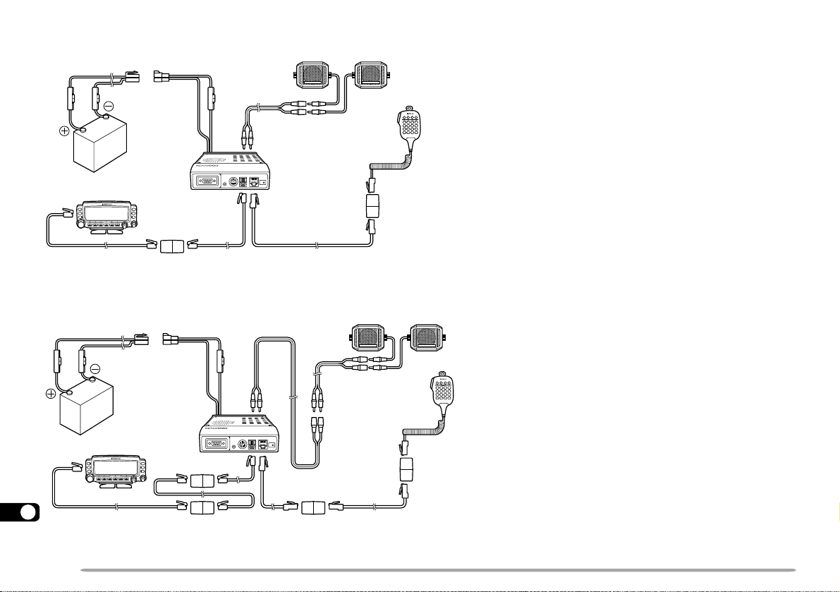
Connections Using One Set of PG-4X Kit
(6 m)
(4 m)
For 6 pins
Connections Using Two Sets of PG-4X Kits
For 8 pins
(4 m)(4 m)
For 6 pins
21
Note: Always connect the 4-pin plug on the modular plug cable supplied
with the transceiver to the front panel.
For 6 pins
For 8 pins
86
For 8 pins
Page 93

MAINTENANCE
GENERAL INFORMATION
This product has been factory aligned and tested to
specification before shipment. Attempting service or
alignment without factory authorization can void the
product warranty.
SERVICE
When returning this product to your dealer or service
center for repair, pack it in its original box and packing
material. Include a full description of the problem(s)
experienced. Include your telephone number along with
your name and address in case the service technician
needs to call you; if available, include also your fax
number and e-mail address. Don’t return accessory
items unless you feel they are directly related to the
service problem.
You may return this product for service to the authorized
KENWOOD dealer from whom you purchased it, or any
authorized KENWOOD service center. Please do not
send subassemblies or printed circuit boards. Send the
complete product. A copy of the service report will be
returned with the product.
SERVICE NOTE
If you desire to correspond on a technical or operational
problem, please make your note legible, short, complete,
and to the point. Help us help you by providing the
following:
• Model and serial number of equipment
• Question or problem you are having
• Other equipment in your station pertaining to the problem
Do not pack the equipment in crushed newspapers for shipment!
Extensive damage may result during rough handling or shipping.
Note:
◆
Record the date of purchase, serial number and dealer from whom
this product was purchased.
◆
For your own information, retain a written record of any maintenance
performed on this product.
◆
When claiming warranty service, please include a photocopy of the
bill of sale, or other proof-of-purchase showing the date of sale.
CLEANING
To clean the case of this product, use a neutral detergent
(no strong chemicals) and a damp cloth.
87
22
Page 94

TROUBLESHOOTING
The problems described in this table are commonly encountered operational malfunctions and are usually not caused
by circuit failure.
eht RWP gnihtoN.hctiws
]PU[ / ]NWD[ .
gninuT tonodlortnoc
.noitcnuf
]PU[ / ]NWD[ .
melborP esuaCelbaborP noitcAevitcerroC
rewoptonlliwreviecsnartehT
1 detcennocsawelbacrewopehT
V8.31agnitcennocretfapu
gnisserpdnaylppusrewopCD
2 sesufelbacrewopehtfoeromroenO
.yalpsidehtnosraeppa
3 tonsawelbacgulpraludomehT
neve,midootsiyalpsidehT
hgihadetcelesuoyhguoht
.levelremmid
ebtonnacycneuqerfehT
ehtgninrutybdetceles gninuT
ciMgnisserpybrolortnoc
ehtdnasyek/snottubtsoM
ebtonnacslennahcyromeM
ehtgninrutybdetceles gninuT
ciMgnisserpybrolortnoc
.sdrawkcab
.nepoera
.detcennocyltcerroc
.wolootsiegatlovylppusehT sitnemeriuqeregatlovylppusehT
.detcelessawllaceRyromeMsserP ]OFV[ .51
.NOsisnoitcnufkcoLehtfoenO.snoitcnufkcoLehtfollakcolnU76
.slennahc
1 elbacrewopCDdeilppusehttcennoC
2 retfA.)s(esufnwolbehtfoesuacehtrofkooL
3 elbacgulpraludomehttcennocyltcerroC
yromemynaniderotsneebsahatadoN
egaP
.feR
6,5
:yltcerroc
deR → kcalB;)+( → .)–(
7
llatsni,smelborpynagnitcerrocdnagnitcepsni
.sgnitaremasehthtiw)s(esufwena
4
.tinuniamdnalenaptnorfehtneewteb
—
CDV8.31 ± .)CDV8.51otV7.11(%51
egrahcer,egnarsihtedistuosiegatlovtupniehtfI
,ylppusrewopdetalugerruoytsujda,yrettabruoy
.snoitcennocelbacrewopllakcehcro/dna
.slennahcyromememosniataderotS63
22
88
Page 95

melborP esuaCelbaborP noitcAevitcerroC
nevetimsnarttonnacuoY
ciMsserpuoyhguoht ]TTP[ .
otsliafrednammoCehT
.reviecsnart
.reviecnartFHehtmorf
FHehtlortnocotuoy
.reviecsnart
oiduaraehtonnacuoY
FHehtybdeviecer
.reviecsnart
1 tonsawgulpenohporcimehT
.rotcennoclenap
2 tahttesffotimsnartadetcelesuoY
.egnar
3 CNTlanretxenaro(CNTni-tliubehT
1 llacmargorpyltcerroctondiduoY
FHehtfosutatsehtyalpsid
2 tcerrocehttcelestondiduoY
3 deepssnoitacinummocdetcelesuoY
oiduatimsnarttonnacuoY
rednammoCehtgnitarepO
1 ehtneewtebecnatsidegralooT
natuptuoottisesuacylpmis
wollatonseoddnapeebrorre
2 tneverpsnoitidnocevawoidardaB
.retropsnarT
.reviecsnart
.)TROPMOC(
.retropsnarT
atadtcerrocstneverp
.snoitacinummoc
.dettimsnartyltcerroc
tnorfehtotniyletelpmocdetresni
ycneuqerftimsnartelbawollaeht
.gnittimsnartsaw)detcennocfi
dnarednammoCehtnosngis
enotemasehttcelestondiduoY
dnarednammoCehtnoycneuqerf
retropsnarTdnarednammoC
gniebmorfsdnammoclortnoc
.rednammoCehtfodnabzHM
1 ehttresnineht,rewopehtFFOhctiwS
2 sserP ]F[ , ]TFIHS[ ”+“rehtienosyldetaeper
edistuoycneuqerftimsnartehtsecalp
3 ciMsserP ]TTP[ dehsinifCNTehtretfa
1 ,retropsnarTdnarednammoCehthtobnO
2 1dnaspb0069tceles,reviecsnartFHehtnO
FHehtnosretemarapnoitacinummoc
3 .”spb0069“tcelesot5–9–1uneMsseccA52
5–9–1uneMnispb0069nahtrehto
1 ecnatsidanihtiwrednammoCehtetarepO
2 sserP ]CNYS[ sutatsehtdaerotyllanoisacco
441ehtnoSSCTCehtNOdehctiwsuoY
.ecalp
niskcilcbatgnikcolehtlitnugulpenohporcim
.elbisivsi”–“ron
.noissimsnart
ehtmargorpot2–4dna1–4uneMssecca
.sngisllactcerroc
.noitcnufputeSuneMehtgnisutibpots
,retropsnarTdnarednammoCehthtobnO
enotemasehttcelesot3–4uneMssecca
.ycneuqerf
awohsotsreviecsnartowtehtswollataht
.gnidaerretem-Selacs-lluf
.reviecsnartFHehtfo
sserP ]ENOT[ .SSCTCehtFFOhctiwsot55
egaP
.feR
8
92
—
97
87
97
—
08
22
89
Page 96
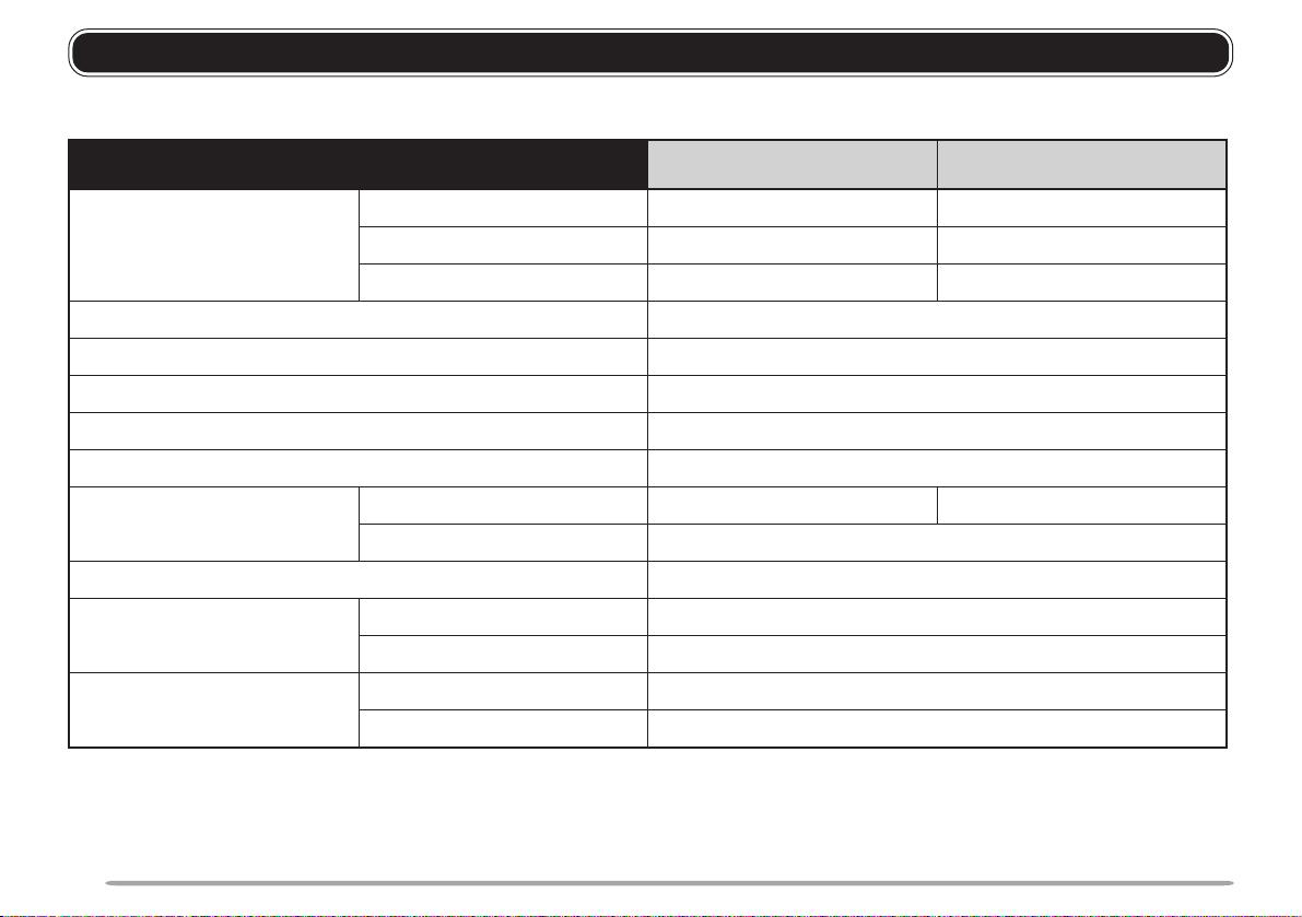
SPECIFICATIONS
Specifications are subject to change without notice due to advancements in technology.
lareneG dnaBFHV dnaBFHU
egnarycneuqerFadanaC/.A.S.U
edoM )KSF(D2F,)KSMG(D1F,)MF(E3F
ecnadepmiannetnA 05 Ω
egnarerutarepmetelbasU 02– ° 06+~C ° 4–(C ° 041+~F ° )F
ylppusrewoP CDV8.31 ± )V8.51~7.11(%51
dohtemgnidnuorG dnuorgevitageN
tnerruC).xam(timsnarTsselroA5.11sselroA0.01
01–(ytilibatsycneuqerF ° 05+~C ° )CnihtiW ± mpp3
1
zHM841~441zHM054~834
eporuEzHM641~441zHM044~034
tekramlareneGzHM641~441zHM044~034
)tuptuoW2ta(evieceRsselroA0.1
DxHxW(snoisnemiD
)dedulcnitonsnoitcejorp
lenaptnorF"03.1x"63.2x"15.5/mm33x06x041
tinuniaM"86.7x"75.1x"15.5/mm591x04x041
thgieWlenaptnorFzo3.6/g081.xorppA
tinuniaMbl6.2/gk2.1.xorppA
1
Band A receive range: 136 ~ 200 MHz, 118 ~ 136 MHz (sub), 200 ~ 300 MHz (sub), 300 ~ 400 MHz (sub), 400 ~ 470 MHz (sub)
Band B receive range: 400 ~ 524 MHz, 136 ~ 175 MHz (sub), 300 ~ 400 MHz (sub), 800 ~ 1300 MHz (sub/ excluding specific
frequency ranges)
90
Page 97
rettimsnarT dnaBFHV dnaBFHU
tuptuorewoPhgiHW05W53
muideMW01.xorppA
woLW5.xorppA
noitaludoM ecnatcaeR
snoissimesuoirupS sselroBd06–
noitaivedycneuqerfmumixaM ± zHk5
)noitaludom%06ta(noitrotsidoiduA sselro%3
ecnadepmienohporciM 006 Ω
revieceR dnaBFHV dnaBFHU
yrtiucriC enydoretehrepusnoisrevnocelbuoD
)dn2/ts1(ycneuqerfetaidemretnI zHk054/zHM58.83zHk554/zHM50.54
)DANISBd21(ytivitisneSdnabFHUroFHV61.0 µ sselroV
dnabFHUroFHVbuS52.0 µ sselroV
)Bd6–(ytivitceleS eromrozHk21
)Bd04–(ytivitceleS sselrozHk82
ytivitisneshcleuqS 1.0 µ sselroV
)noitrotsid%5,smho8(tuptuooiduA rehgihroW2
ecnadepmituptuooiduA 8 Ω
Note: Receiver specifications apply only when using the main VHF or UHF band. They do not apply to the sub VHF or UHF band.
91
Page 98

Advanced Intercept Point
(AIP) .................................... 69
Automatic Band Change
(A. B. C.).............................. 66
Automatic Power Off
(APO) .................................. 70
Automatic Simplex Check
(ASC) .................................. 33
Autopatch ............................ 59
Channel Display................... 40
Continuous T one Coded
Squelch System (CTCSS)
Freq. ID ............................ 56
Using................................ 55
Digital Code Squelch (DCS)
Code ID............................ 58
Using................................ 57
Display
Blanking ........................... 66
Contrast ........................... 65
Demonstration .................. 71
Dimmer, Changing............ 65
Reversal ........................... 65
Dual Tone Multi-Frequency
(DTMF) Functions
Making Calls..................... 59
Pause Duration................. 61
Storing Numbers .............. 60
Transmitting Stored
Numbers .......................... 61
TX Speed ......................... 61
92
INDEX
Frequencies, Selecting
Microphone [UP]/ [DWN] .. 20
Tuning Control.................. 20
Frequency Step Size............ 64
Fuses, Replacing ................... 7
Keypad Direct Entry
CTCSS Freq. Number ...... 56
Frequency ........................ 63
Memory Channel
Number ............................37
Tone Freq. Number .......... 30
Lock
All-control Lock.................67
Transceiver Lock .............. 67
Memory Channels
Call Channel, Changing.... 39
Call Channel, Recalling .... 39
Clearing............................ 37
Locking Out ...................... 51
Naming............................. 38
Recalling .......................... 37
Storing, Odd-split.............. 36
Storing, Simplex ............... 36
Transfer to VFO................ 40
Menu
Access ............................. 22
Configuration .................... 23
Microphone Control .............73
Offset
Automatic Repeater.......... 31
Direction ........................... 29
Frequency ........................ 29
Power-ON Message ............ 71
Programmable Function
(PF) Keys ............................62
Programmable Memory (PM)
Auto Storing ..................... 45
Recalling .......................... 44
Resetting .......................... 45
Storing.............................. 44
Programmable VFO.............64
Repeater Access.................. 28
Repeater Function
Cross-band....................... 82
Locked-band .................... 82
Reset
Full (Memory) ................... 41
Partial (VFO) .................... 41
Programmable Memory
(PM) ................................. 45
Reverse Function................. 33
Scan
Call/Memory ..................... 54
Call/VFO .......................... 54
Carrier-Operated
Resume............................ 49
Group ............................... 51
Memory ............................ 50
MHz ................................. 53
Program ...........................52
Time-Operated Resume ... 49
VFO ................................. 50
Visual ...............................47
Sky Command 2 ................ 76
Speaker
Configurations, changing .. 72
Mute ................................. 72
Squelch
Adjusting ..........................20
S-meter ............................68
Switching FM/AM................. 69
Time-Out Timer (TOT).......... 70
Tone
Activating.......................... 30
Freq. ID ............................ 34
Selecting ..........................30
Transmit Output Power ........ 21
TX/RX Deviation ..................72
Voice Synthesizer (VS-3) ..... 83
Volume
Audio................................ 19
Beep ................................ 69
Wireless Remote Control .....74
Page 99

 Loading...