

Page 1

144/220 MHz FM MULTI BANDER
7\
m
O
TM-641A
144/440 MHz FM MULTI BANDER
TM-741A
144/430 MHz FM MULTI BANDER
TM-741A
144/430 MHz FM MULTI BANDER
TM-741E
INSTRUCTION MANUAL
KENWOOD CORPORATION
O
a
©PRINTED IN JAPAN B62-0082-10(K)(T)
92/12 11 10 987654321 91/12 11 10 9 8 7 6
Page 2

Thank you for purchasing this new transceiver.
IMPORTANT:
Please read this instruction manual carefully before
placing your transceiver in service.
CAUTION;
Long transmission or extended operation in the HI
power mode might cause the rear of this transceiver to
get warm.
Do not place the transceiver where the heat sink (rear
panel) might come in contact with plastic or vinyl
surfaces.
This instruction Manual covers the following models.
TM-641A: 144/220MHZ FM MULTI BANDER
(U.S.A.version)
TM-741A: 144/440MHZ FM MULTI BANDER
(U.S.A. and Canadian version)
TM-741A: 144/430MHZ FM MULTI BANDER
(General markets)
TM-741E: 144/430MHZ FM MULTI BANDER
(European markets)
NOTE: If disregarded, inconvenience only, no
risk of equipment damage or personal
injury.
CAUTION: Equipment damage may occur, but not
personal injury.
Save this instruction manual.
Illustrations show the TM-741A.
FCC WARNING
This equipment generates or uses radio frequency
energy. Changes or modifications to this equipment
may cause harmful interference unless the
modifications are expressly approved in the
instruction manual. The user could lose the authority
to operate this equipment if an unauthorized change
or modification is made.
Page 3

CONTENTS
1. BEFORE OPERATION
2. SPECIFICATIONS and ACCESSORIES
3. INSTALLATION INSTRUCTIONS
4. OPERATION
4-1 OPERATING CONTROLS
Front Panel ................................................... 12
Microphone .................................................. 16
Display Panel ............................................... 18
Rear Panel and Side case
4-2 RECEIVER OPERATION
Receiver Operation ...................................... 21
Frequency Selection
Frequency Step Selection
ProgrammableVFO Tuning Limits ... 23
A.B.C.(Automatic Band Change)
Band Selection ............................................. 25
Attenuator ON/OFF
ALT (Automatic Lock Tuning)
4-3 TRANSMITTER OPERATION
Transmission
TX Alert ....................................................... 27
Time-Out Timer (TOT)
Bandwidth Selection .................................... 28
.......................................................
.........................................
......................
...............................
.............................
................................
....................................
............................
................
.....................................
...................
........................
...............................................
...............................
..............
12
12
20
21
22
22
24
25
26
27
27
28
5
6
8
4-4 MEMORY ......................................................... 29
.Microprocessor Memory Back-up
Microprocessor Initialization
Memory Channels
Memory Contents ........................................ 30
Memory Entry ............................................. 31
Memory Channel Recall
Memory Banks
Clearing Memory
.Memory Shift
4-5 SCAN ................................................................ 36
Scan Options
Hold/Resume Programming ........................ 36
Band Scan
Programmable Band Scan
.MHz Scan ................................................... 38
Memory Channel Scan ................................ 38
CALL Scan .................................................. 39
V/M/CScan .................................................. 39
Automatic Memory Scan
.Memory Channel Lockout
4-6 REPEATER OPERATION
Transmitter Offset
Reverse Function
Tone and CTCSS Operation
Autopatch Operations
...................................................
.......................................
.............................
...........................................
........................................
.............................................
...............................................
...........................
............................
.........................
...............................
.......................................
........................................
.................................
.............
......................
.......................
29
29
30
32
32
35
35
36
37
38
39
40
41
41
41
41
43
Page 4

4-7 DTSS
4-8 PAGING ......................................................... 46
4 - 9 TONE ALERT SYSTEM................................ 51
4-10 AUTOMATIC POWER OFF (APO)
4-11 DIMMER (DIM)
4-12 BEEP TONE LEVEL ADJUSTMENT.... 53
4-13 BEEP TONE FREQUENCIES ....................... 53
4- 14 KEYLOCKS ................................................... 54
5. CLOCK ................................................................ 55
5 -1 CURRENT TIME AND DATE
5- 2 OTHER CLOCK FUNCTIONS
..............................................................
DTSS Code
DTSS Code Selection
Using the DTSS Function ............................ 45
Using DTSS with a Repeater ....................... 45
Paging Code Memories
Code Selection ............................................. 47
Code Transmission
Paging Code Monitoring
Code Lockout
Backup Switch.............................................. 55
Setting the Current Time and Date
Current Time, Calender and Stopwatch in the
Clock display
Time-ON/Time-OFF Programming
Activating the SLEEP Timer
..................................................
..................................
...............................
......................................
.............................
..............................................
.............
............................................
......................
..............
.....................
...............................................
.............
........................
44
44
44
47
48
49
50
52
52
55
55
56
56
57
57
5 - 3 CLOCK POSITION ON THE FREQUENCY
DISPLAY
Transceiver Function ON or OFF
Transceiver Function OFF
Transceiver Function ON
Tri-Bander
Clock Operation in the Frequency Display 60
6. MAINTENANCE
In Case of Difficulty .................................... 62
7. OPTIONAL ACCESSORIES
CTCSS unit (TSU-7) 65
DTMF unit (DTU-2) 65
Panel Separation Kit (PG-4K^ PG-4L) 68
Bracket
Band Unit
BLOCK DIAGRAM and SCHEMATIC DIAGRAM
One additional band may be installed using options
described in this manual. Operation instructions
remain the same for the radio when uses a dual band
or tri-band configuration.
......................................................
...............
...........................
.............................
...................................................
................................................
..............................
........................................................
...................................................
........................................ another sheet
NOTICE
58
58
58
59
59
61
64
70
71
Page 5

1. BEFORE OPERATION To prevent electric shock, fire and other
injury, please note the following:
Never remove the case unless instructed to do
in this Instruction Manual. If the internal
parts are touched accidentally, a serious
electric shock might occur.
Do not place the unit in areas of excessive dust,
high humidity or on unstable surfaces.
Do not drop pieces of metal, needles, coins and
other electrically conductive materials into the
unit.
Do not touch the power plug, when your hands
are wet.
Do not place this unit where it will be exposed
to direct sunlight or close to heating
appliances.
Do not place anything on top of the cabinet.
To ensure good ventilation, do not put
anything on top of the cabinet and allow at
least 15 cm (6 inches) of space behind the unit.
The power requirement is 13.8 VDC.
Never attempt connection to a 24 VDC source.
If an abnormal odor or smoke is detected,
immediately turn the power off. Contact the
KENWOOD service station or your dealer.
Cleaning
1. Turn the power off before cleaning the unit.
2. Do not use any type of abrasive pad, thinner, benzine
or any substances which may damage the unit.
3. Wipe the front panel and other exterior surfaces of
the unit with a soft dry cloth or a soft cloth lightly
moistened with water.
Page 6

2. SPECIFICATIONS and ACCESSORIES 2-1. SPECIFICATIONS
M
G
E
N
E
R
A
L
T
R
A
N
S
I
T
T
E
R
144 MHz Band
Frequency
range MHz
Mode
Antenna impedance
Operating temperature
Power requirements 13.8VDC±15% (11.7~15.8V)
Ground
Current drain
Frequency stability
Dimensions (WXHXD) 150X50X175 mm
Wa^ 1.6 kg
Output
power
Modulation
Spurious radiation Less than —60dB
Maximum frequoxy cfeviation
Audio distortion (at 60% modulation)
Microphone impedance
U.S. A and Canada 144 ~148
Other market 144 ~148 —
TM-741E
Transmit mode
Receiver mode
HI
MID
LOW Approx. 5W
144 ~146 —
Less than 11.5A
50W 25W
220 MHz Band
220 ~225
F3E(FM)
50D
-20'C~+60X (-4T~ +140°F)
N^ative
Less than 7.0A
Less than 1.2A
±10ppm
low
Reactance modulation
±5kHz
Less than 3%
6oon
440/430 MHz Band
438 ~450
430 ~440
430 ~440
Less than lO.OA
35W
Page 7

144 MHz Band
R
E
C
E
V
E
R
NOTE: 1. Circuit and ratings are subject to change without notice, due to developments in technology.
Circuitry
Intermediate frequency lst/2nd
Sensitivity (12 dB SIN AD)
Selectivity —6 dB
Selectivity —60 dB
I
Squelch sensitivity
Output (5% distortion)
External speaker impedance
2. Recommended duty-cycle: 1 minute Transmission, 3 minutes Receptioa
10.7 MHz/455 kHz
Double conversion superheterodyne
More than 2 W (8D load )(5% distortion)
220 MHz Band
30.825 MHz/455 kHz
Less tJian0.16;[/V (—10 dB/z) ^
More than 12 kHz
Less than 24 kHz
Less than 0.1 /¿V (—14dB//)
8D
440/430 MHz Band
21.6 MHz/455 kHz
2-2. ACCESSORIES
Unpack your transceiver carefully and confirm that the
accessories listed below are included in the box.
DTMF Microphone
( U.S.A. and Canada only)
or Microphone
(European version)
or Microphone
Microphone Hook..................... J20-0319-XX 1
( U.S.A. and Canada only)
Mobile Mounting Kit.................................................... 1
Bracket
Screw set ....................... N99-0331-XX
.................
..........................
..........................
(General market)
..........................
T91-0397-XX
T91-0398-XX
T91-0396-XX
J29-0454-XX
............
............
............
1
1
1
Self tapping Screw
...................
N46-3010-46
............
2
(U.S.A. and Canada only)
Hex Wrench
DC power Cable
............................
......................
W01-0414-XX .... 1
E30-3034-XX .... 1
FusedSA) ................................. F05-1531-XX .... 1
Instruction Manual
Quick reference
Warning sheet
..................
.......................
.........................
B62-0082-XX 1 copy
B59-0441- x x 1 copy
B58-1001-XX 1 copy
Warranty Card (U.S.A., Canada and European version
only) ............................................................................ 1
After unpacking
Shipping container: Save the boxes and packing in the
event your unit needs to be transported for remote
operation, maintenance, or service.
Page 8

3. INSTALLATION INSTRUCTIONS 3-1. INSTALLATION
3-1-1. Installing the Microphone and Setting
the Clock Backup Switch
Before installing be sure to turn off the power switch.
1. Slide the release button on the front panel to the
right. Carefully pull the front panel toward you from
the right, then remove the whole panel unit. Be
careful with the cord connecting the front panel unit
to the chassis. (Fig. 1)
2. Insert the microphone connector into the microphone
socket on the right of the main unit until it clicks.
Make sure the tab on the connector is on top.
3. Place the microphone cord in the holder groove. (Fig. 2)
■BACKUP SWITCH
Inside the small cover of the front panel unit there is
a Backup Switch to retain clock memory. If you set
the switch ON »turning off the POWER switch,
disconnecting the power cable or an intermittent
power failure will not erase the clock memories.
4. Slide the small cover off of the front panel unit as
shown in the accompaning illustration. (Fig.3)
5. Gently lift up on the cable near the grommet.
6. Set the Backup switch ON. Pay attention to the labelings.
7. Push the grommet down into its slot.
8. Replace the small cover until it clicks.
9. Route the cable as desired
in the slots on the rear of
the front panel.
1 ^
1%
---------
[
)
10. Align the hook on the back of the front panel with
the slot on the left of the chassis before replacing the
front panel.
11. Push the front panel toward the chassis until it locks
completely. Take care not to trap the connecting
cord.
The connecting cord is easier to manage when it is
put in the groove on the back of the front panel.
12. Set the date and time ( See page 55 ).
(Fig. 1)
microphone
connector
release button
slot
holder
(Fig. 2)
8
(Fig. 3)
Page 9

3-1-2. Mounting Bracket
Notes
1. When installing the transceiver in a vehicle
consider ease of operation and safety when selecting
the location for the mounting bracket.
2. Install the bracket securely so that it will not come
off due to vibration.
1. Install the bracket
using the supplied flat
washers and self
tapping screws (4 pcs.
each).
2. Attach the transceiver
loosely using the
SEMS screws (4 pcs.).
3. Adjust the viewing angle of the bracket to the desired
position.
3-2. CONNECTION
3-2-1. Antenna
The type of antenna that is used will greatly affect the
performance of the transceiver. Use a properly adjusted
antenna, of good quality, to enable your transceiver to
perform at its best. The antenna input impedance is 50
ohms. Use 50-ohm coaxial cable such as RG-8U or 8D2V for this connection. If the antenna is far from the
transceiver the use of low loss coaxial cable, such as RG8U is recommended. Match the impedance of the coaxial
cable and that of the antenna so that the SWR is less
than 1.5 to 1. The protection circuit in the transceiver
will activate if the SWR is particularly poor (greater
than 3 to 1).
High SWR values will cause the transmitter output to
drop, and may lead to TVI or BCI reports.
Caution;
We recommend that you install a high quality
lightning arrestor in your antenna lines for
protection against fire,electric shock,personal
injury,or damage to the radio itself.
Hold the transceiver in place and tighten the 4 SEMS
screws using the supplied wrench.
Page 10

3-2-2. Mobile Installations
Battery Connections
Cautions
1. Before installing the power cable, be sure to remove
the negative lead from the battery for safety.
2. After installation and wiring, be sure to double
check for correct installation before reconnecting
the negative lead to the battery terminal.
3. If the fuse opens, be sure to check that each
conductor has not been damaged by short circuiting,
etc. Then replace with a new fuse of the same
rating.
4. After completing the wiring, wrap the fuse holder
with heat resistant tape to protect against heat and
moisture.
5. Do not remove the fuse even if the power cable is too
long.
Make sure the positive (+) and negative (—) lead polarity is
correct when connecting to the battery.
Engine compartment-——-Passenger compartment
Red
Fuse 0 f
\ To the
\transceiver
/
select a location wh«re
the power cable ¡8 pro
tected from heat, mois
ture or abrassion when
securing the cable.
If the wiring hole in the fire wall or chassis is too small,
disassemble the fuse holder to thread the wire through the
hole.
________
Chassis or
"^fire wall
j£
Make sure the cable
does not directly contact
the edge of the hole by
using a grommet.
From passenger
compartment
Thread like this
Caution
Leave enough space around the fan on the rear panel
for good ventilation.
Connect the power cable directly to the battery
terminals. Use of the cigarette lighter socket will lead to
poor connection, and will result in poor performance.
Pay close attention to the polarity of the cables when
connecting them to the battery.
10
Page 11

3-2-3. Fixed Station
A regulated DC power supply (13.8 VDC capable of
supplying at least 12 Amperes) is required. The PS-430
and the PS-50 are recommended.
Caution:
1. Never connect the AC power cable to the AC outlet
until all other connections have been made.
2. Before connecting and disconnecting the power
connector, be sure to turn OFF the POWER
switches of both the transceiver and the DC power
supply.
3. Observe polarity of the DC power cable. The
transceiver operates on 13.8 VDC, negative
ground. Battery polarity must be correct. The
power cable is color coded :
Red + (Positive polarity)
Black — (Negative polarity)
Caution:
Leave enough space around the fan on the rear panel
for good ventilation.
11
Page 12

12
Page 13

CONTROL SEITECT keys (Press) / Current Operating Band indicators
These keys are used to select the key operating band.(To change the transmission
band, use the BAND SELECT key.)
The green light shows which band will be controlled by the front panel controls.
When optional
band unit is
installed.
BAND SELECT keys (Press) / VOL controls {Rotate)
These keys are used to select the transmit band. They are also used to select
the band you wish to control with the front panel switches. When a key is
pressed the ”PTT” indicator will flash as a visual signal to show which band
has been selected.
SQL (Squelch)
controls
These controls
are used to
separately adjust
each squelch
threshold level.
VOL controls (Rotate)
These controls are used to adjust the volume.
13
Page 14
14
Page 15

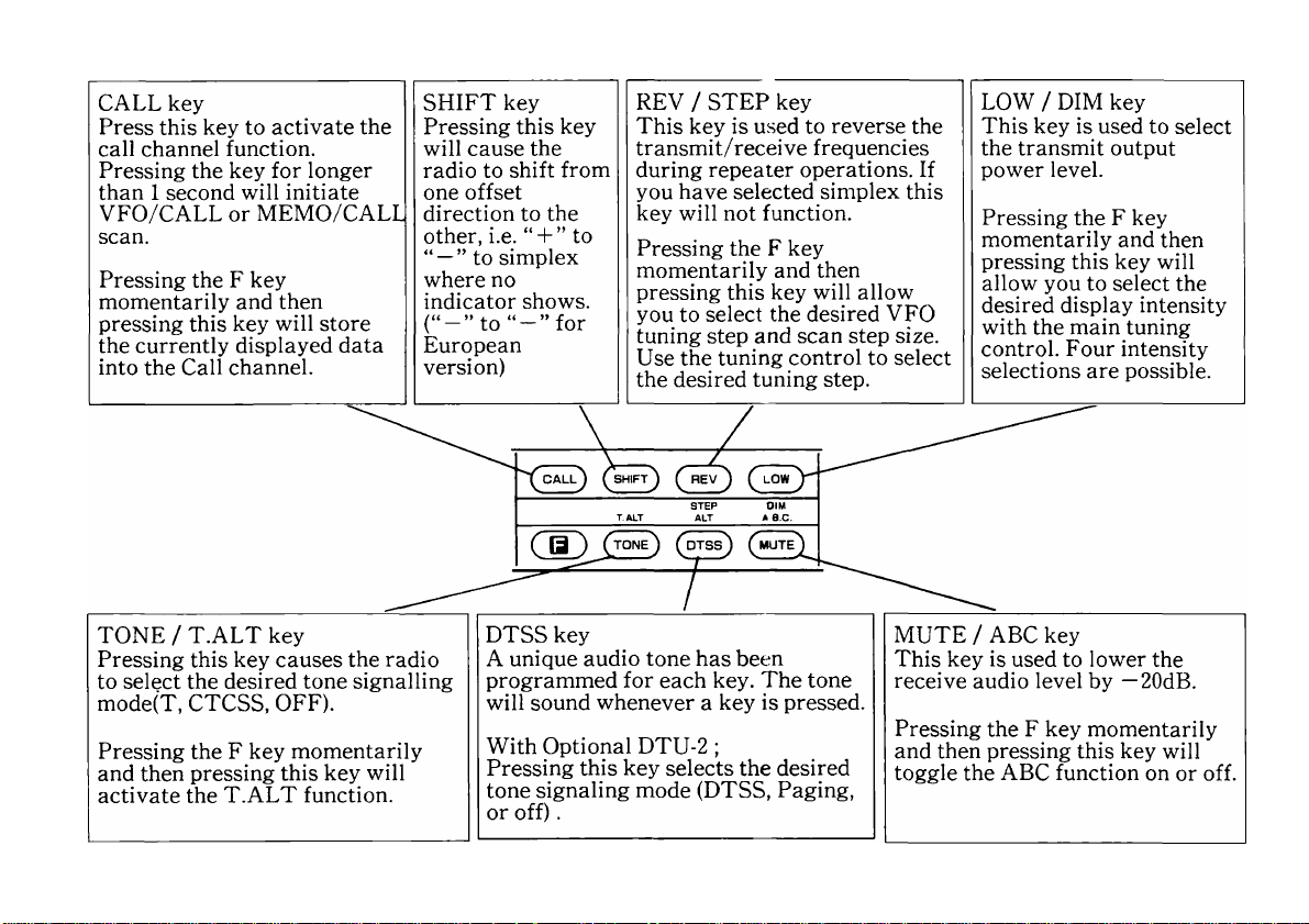
I Function key Assignments
Press the F key for longer than 1 second so that the
key indicator begins to flash, then press the key
below.
Key
F 1 Sec,
F 1 Sec,
F1 Sec,
F 1 Sec,
F 1 Sec,
F 1 Sec,
F 1 Sec,
F 1 Sec,
F 1 Sec,
F 1 Sec,
CONT SEL
F 1 Sec,
BANDSEL
VFO
MR
MHz
CALL
SHIFT
TONE
REV
DTSS
LOW
Automatic Power off functior
Function
Change Scan Hold/
Resume mode
Memory channel lockout
will turn on or off
The lower limit of the
programmable VFO
The upper limit of the
programmable VFO
Tone frequency selection
Beep tone level adjustment
DTSS code selection
Time-out timer on or off
Select receive detection
output band from the
microphone connector
Band on or off
Refer to
P.36 4-5-2
P.40
P.52
P.23 4-2-4
P.23 4-2-4
P.42
P.53
P.44 4-7-2
P.28
P.18 4-1
P.25 4-2-6
4-5-10
4-10
4-6-3
4-12
4-3-3
• Press and hold the F key, then the key
Key Function
F+ VFO
F+ MHz
F+ MR
F+ TONE
F+ DTSS
F+ LOW
F+
CONT SEL
F+
BAND SEL
F+ PIT
Enter the programmable scan
lower frequency limit
Enter the programmable scan
upper frequency limit
Clear the displayed memory
channel data
Bank status display
DTSS delay time selection
Memory consolidation
Automatic Memory scan
Clear Memory Bank
TX Alert
DClow.
Refer to
P.38 4-5-4
P.38 4-5-4
P.35 4-4-8
P.32 4-4-7
P.45 4-7-4
P.32 4-4-7
P.39 4-5-9
P.35 4-4-8
P.27 4-3-2
• Press and hold the key below and turn on the power
switch.
Key Function
MR +
Power ON
F+BANDSEL
+ Power ON
Memory reset of all bands
Memory reset of a band
Refer to
P.29 4-4-2
P.29 4-4-2
15
Page 16

Key
VFO+
Power ON
VFO-i-BANDSEL
-I- Power ON
MHz+
Power ON
CALL+
Power ON
F+SHIFT+
Power ON
F+TONE+
Power ON
F+DTSS+
Power ON
F-I-LOW +
Power ON
Function
VFO reset of all bands
VFO reset of a band
All lock on or off during Lock
Demonstoration mode
on or off
Tone alert selection
Set the time and date
With optional DTU-2:
The microphone PF key can
be used to change the beep
tone frequency.
Wide /Narrow selection
Refer to
P.30 4-4-2
P.30 4-4-2
P.54 4-14
P.40
P.51 4-9
P.55 5-1-2
P.66 7-3-1
P.28 4-3-4
4-1-2. Microphone
(2) ®
®d)UP/DWN switches
These switches can be used to increase or
decrease the VFO frequency, the Memory
channel number, and the Tone frequency, etc..
d)PTT (Push to Talk) switch
The transceiver will transmit whenever this
switch is depressed. Scan operations may be
canceled by pressing this switch without
transmitting.
0LOCK switch
This key will deactivate all functions of the
microphone except the PTT function and DTMF
keypad.
(Dl6-Tone DTMF keypad
These buttons are used to activate the DTMF
encoder.
16
Page 17

(DPF(Programmable Function) key
This key can be programmed to perform any of the
following functions: BAND SEL (*^) key (Initial setting
from the factory); or MHz, T.ALT, TONE, REV, DTSS,
LOW, MUTE, or CONT SEL (^) key.
To program the key use the following procedure:
1. Turn off the POWER switch on the transceiver.
2. Press and hold the key on the front panel of the set
that corresponds with the function you wish to
program the microphone key to perform.
3. Turn on the POWER switch while the key on the
front panel is held in.
4. Release the front panel key.
(^) Press the PF key set in the CONT SEL or BAND
SEL key to cause the radio to switch from a band to
the other. Pressing the PF key for longer than 1
second will not initiate scanning
Press the PF key set in the CONT SEL or BAND
SEL key to cause the radio to switch from one band
to the other. Pressing the PF key for longer than 1
second will not initiate scanning.
Press and hold the F key on the front panel as you turn
on the POWER switch of the transceiver and then
release the F key.
(2X:ALL key VFO key MR key
These keys function are like the CALL, VFO,or MR key
on the front of the radio. (See page 12.and page 14)
These keys can be programmed to function as the PF
key.
To program the key :
1. Turn off the POWER switch on the transceiver.
2. Press and hold one of these keys.
3. Turn on the POWER switch. The PF-2/3/4 will
appear in the display.
4. Press the key on the front panel that you wish to
program the microphone key.
5. Release the microphone key.
To release the programming reset the VFO.
(saSffflSs issBBRBs ibbBBBBs^
iBBni I I
One additional function can be programmed that is not
included on the front panel of the transceiver. This is
known as the MONITOR function. This will allow you to
open squelch of the selected band to check the band for a
clear frequency. This will function even if you are
operating in the CTCSS decode mode.
MONITOR programming
Turn on
Press and hold MR key............................... PF2
MR key.............................. PF3
MR key.............................. PF4
(Dl750key (European version)
The transceiver will transmitt with 1750 Hz repeater
access tone whenever this switch is depressed.
17
Page 18

►Microphone terminal connection
(Front view)
4-1-3. Display Panel
Receive audio for
the selected TX
band
(100mV/l0kn)
Receive Audio Output Band Selection (RD) connector
The RD terminal will supply an audio signal during
receive on the same band that has been selected for
transmit. Press the F key for longer than 1 second, and
then press the CONT SEL key for the desired band. An
indicator will appear in the frequency display of the
selected band.
/
-----
lOHS
Receive Audio output display
The 100 kHz dot in the band lights
L, rr n n o
Wl /.u u u
18
(9>
(p
—+
)REV
®CTCSS
)DTSS
)CO
/1 o o ^ c
LLCfO U.U:U.U
^Bgr
BU SY
SSRF—1 — B — a
(ij)
IlllllllllllllrS^
Indicates the TX band.
Displays the selected transmitter offset
direction.
On when the Reverse function has been
activated.
With the optional CTCSS unit TSU-7: On
when the Tone Decode function is active.
On when the Tone Encode function is
active.
With optional DTU-2
On when the DTSS function is active.
On when Carrier Operated scan is
selected.
On when the Tone Alert function is
active.
L,M
Page 19

&
—+
REV
CTCSS CO
DTSS ^
SO.
— +
REV
CTCSS CO
DTSS ^
Ts 8.8:8.8s Шв88:8.8.1 !Ts 88:8.8.
*88 'Ш“!!1Ч“Ч!Ш SI *88 |ИРдаччч<Ш SI *88 в»'Ш!Ш|Ш! SI
^188 Displays the operating frequency to the ®
nearest kHz digit, or the tone frequency. f-------1—
• The indicator flashes when scanning.
■ On when receive detection output is fixed
in the band. © ni^
s
*B 8
PB
L M
On whenever the F key has been OFF
depressed. © SLEEP
Shows the last memory channel number
that was selected. The ★ indicator is on © LOCK
when the Memory channel will be skipped
during Memory channel scan. A,LOCK
On in paging mode.
-On when the squelch opens. @ apo
This level meter indicates the relative
receiver signal strength or the relative @ TOT
transmitter power output.
On during transmit. @ д.В.С.
Indicates the relative output power
setting for transmit. No indicator @> MUTE
indicates full power.
■4ЕШ^
SO
__
CTCSS CO m ON
Чжг
_ A.LOC
C AP
J TOT
A.B.C
MUTE
1200MHz band only; On when the Automatic
-Lock Tuning function is active.
28/50 MHz band only; On when Attenuator is
on.
On when the TIME ON/OFF function has
been activated.
On when the SLEEP TIMER function has
been activated.
On when the Lock function has been
activated.
On when the All Lock function has been
activated.
On when the Automatic Power Off
function has been activated.
On when the Time-Out Timer function
has been activated.
On when the Automatic Band Change
function has been activated.
On when the volume of the RX band is
reduced.
19
Page 20

4-1-4. Rear Panel and Side Case
144MHz.
■ 144MHz
P
TM-741A/741E-
440/430MHZ
TM-641A
220MHz
w
J
(DANTENNA connector
Attach an antenna with a low SWR and impedance of 50
ohms.
(2) 13.8 VDC power input connector
Connect the supplied DC power cable to this connector.
Pay close attention to the polarity. Red is positive and
black is negative.
(DFuse holder
Contains a 15A fuse. Do not use a larger fuse as
damage might result to the transceiver.
(3) External speaker jack (Rear panel)
The speaker should have an impedance of 8 ohms.
The audio is switched to the external speaker (no sound
is output from the built-in transceiver speaker).
■TM-741A/741E
440/430MHZ
TM-641A
220MHz
Example
144MHz band
(5)External speaker jack (Side case)
The speaker should have an impedance of 8 ohms.
The audio is switched from the built-in transceiver
speaker to the external speaker (no sound is output from
the built-in transceiver speaker).
Example
We recommend the use of the optional external speaker
SP-50B.
20
Page 21

Fig.l
2. Turn on the Power Supply, then turn on the
transceiver’s POWER switch. The display should
light after 1 second. Fig.l shows examples of
frequencies that will appear on the various models.
The frequencies shown above are the default
frequencies after a microprocessor reset. If the
display shows incomplete data or you think the
displayed frequency is in error you should reset the
microprocessor. ( Memory Initialization on page 29 )
Perform the following steps for each band.
so that the operating band indicator lights (green).
Rotate the VOL control clockwise until a signal or
noise is heard coming from the speaker.
4. Rotate the tuning control or press the microphone
UP/DWN switches to select an open channel.
5. Rotate the SQL control clockwise until the noise just
disappears and the BUSY indicator turns off. This
point is known as the Squelch Threshold point.
6. Select the desired operating frequency using the
microphone or tuning control. When a signal is
received the S-meter will deflect and the BUSY
indicator will turn on.
21
Page 22

7. Turn off the transceiver’s Power switch before you
turn off the power supply, or in a vehicle, before you
stop the engine.
4-2-2. Frequency Selection
You can change the dial frequency while in the VFO
mode. The frequency can also be stored in memory, or in
the call channel.
1. Press the VFO key to select the VFO mode.
2. Rotate the tuning control, or press the microphone
UP/DWN switches to select the desired frequency.
Mode selection
You can select the VFO mode. Memory channel mode, or
Call channel mode using the following keys.
1. Press the VFO key to select the VFO mode.
2. Press the F key momentarily. The F indicator should
light on the display.
3. Press the REV/STEP key within 10 seconds of
pressing the F key. The current frequency step size
will be displayed.
4. Rotate the Tuning control or press the microphone
UP/DWN keys until the desired tuning step size
appears in the display.
CS)
tons
,1,. n o n n
5
GE)
step Size [kHz]
5^10^15?i20?=i12.5=i25i*
5. To complete the programming of the step size you can
press any front panel key or simply wait 10 seconds
and the microprocessor will automatically return to
the normal frequency display.
4-2-3. Frequency Step Selection
T0 select the desired tuning or scan step size use the
following procedure:
22
Page 23

The chart below illustrates the way the displayed
frequency will change when you change from one step
size to another.
5,10,15,20 to 12.5,25
0,5,10,15 0
20,25,30,35 25
40,45,50,55 50
60,65,70,75,
80,85,90,95
75
12.5,25 to 5,10,15,20
0
12.5
25
37.5
50
62.5 60
75
87.5
0
10
20
30
50
70
80
For example:
Assume you are presently displaying a frequency of
439.920 MHz and had previously selected a 20 kHz step
size. If you were to change the step size to 12.5 kHz the
display would then read 439.925 MHz.
1. Press the VFO key to select the VFO mode.
Rotate the Tuning control until the desired lower
tuning range appears on the frequency display.
For example, you might want to select the 438 MHz
band and dial up 438.100 MHz.
2. Press the F key,for longer than 1 second, then press
the CALL key.
more than
1 sec
3.
Rotate the Tuning control until the desired upper
/¿7VS
^unnn inn
iW i.uuu '<30. luu
tuning range appears on the frequency display.
Press the F key for longer than 1 second, then press
the SHIFT key.
4-2-4. Programmable VFO Tuning Limits
The radio provides the capability of programming the
VFO tuning range, in 1 MHz band segments, as well a
providing a separate programmable band scan function.
(See section 4-5.) For example, you could tell the
transceiver that you only wish to tune the 438.000 MHz
and 439.000 MHz band segment by specifying any
frequency with these two segments. The Tuning controls
would then only tune within these specific bands. The
procedure for specifying the bands is described below.
dj r
lore than
1 sec
(^3HIFT^
To confirm that the programming was properly
5.
performed rotate the Tuning control.
The transceiver should not go above or below the
programmed band limits.
IriuC ^unnn mn
lu iD H I.UUU '<30. luu
23
Page 24

To clear both programmed limits simultaneously,
turn the Power off ,then;
ALL BAND mode
Press and hold the VFO key, then turn the Power
switch on (VFO RESET See page 30).
INDIVIDUAL BAND mode
2. As soon as a signal is received on any band, the TX
circuit will become active on that band.
(
lOHS
,^unnn ff^.nnnn
I'il.UUU Wu.uuu
Press and hold the VFO key and the BAND SEL key
for the band you want to clear, then turn the Power
switch on.
You can reprogram either limit independently by fol
lowing the appropriate instructions above.
4-2-5. A.B.C.(Automatic Band Change)
The A.B.C function allows you to exchange the RX band
to the TX band automatically whenever a signal is
received and the squelch is open.
1. Press the F key and then press the MUTE/ABC key.
The A.B.C. indicator will light on the display.
24
(Jj
A.B.C.
(^MUTE^
lUlD IHi.uuu 'iHu.uuu
'^ .un nn .,.,nnnn
3.
If you press the PTT switch,
The A.B.C. function will be released. The band
remains TX band.
If the PTT switch is not pressed,
Within 2 seconds after the signal goes off, the band
will be returned to RX band.
If you press the BAND SEL key.
The A.B.C function will be released.
Page 25

4-2-6. Band Selection
1. Press the F key for longer than 1 second. The F
indicator will begin to flash.
Press the BAND SEL key for the bands you wish to
turn on/off. A Calender will be displayed.
4-2-7. Attenuator ON/OFF
(Requires optional BAND UNIT UT-28S or UT-50S)
When the incoming signal is very strong, the signal
should be attenuated to prevent distortion of the signal,
thereby stabilizing the receiver performance.
more than 1 second
I nu c ‘^unnn
lUTJ I’^l.UUU
31
123
2. Press the BAND SEL key again.
When turning off a band an “off“ will be displayed in
the display for approximately 10 seconds then the
appropriate band display will come back.
10:33
i033
'^unnn
13 n.uuu
unnn
13 l.UUU
-OFF-
4
3. To retern to the previous display press the F key for
longer than 1 second then press the BAND SEL key.
It is possible to turn off all three bands. In this case no
frequencies will be displayed.
1. Press the CONT SEL key or the BAND SEL key for
the 28/50MHz band.
2. Pressing the F key momentarily then pressing the
DTSS key will toggle the ATTENUATOR function on
or off. The attenuator indicator will turn on when the
function is active.
Attenuator indicator
i
----------
i
-I o c o n
d Ji.JiQU
BUSY
SS RF —1
lllllllllllllll
25
Page 26

4-2-8. ALT (Automatic Lock Tuning)
(Requires optional BAND UNIT UT-1200 )
The ALT system operates similar to an AFC (Automatic
Frequency Control) system. This system is useful when
the frequency of either station starts to drift. When this
occurs distortion of the signal is the usual result. The
ALT system will detect the drift and shift the frequency
to compensate.
1. Press the F key momentarily. The F indicator will
light on the display.
2. While the F indicator is on press the DTSS/ALT key.
The ALT indicator will turn on and the receiver will
automatically center itself on the incoming signal.
The frequency display will not actually change, even
though the receive frequency might shift in order to
properly tune the incoming signal. When the ALT
system is operating the direction indicator in the display
will turn on to signal a change in the receiver
frequency.The direction indicator will show you if the
incoming signal is higher or lower than the displayed
frequency.
Turns on when the transmit frequency of the
distant station is higher than your receive
frequency.
—-
.... nnnn
'iHu.uuu
nnnn
IPHu.uuu
—
(^DTSS^
3.
To release the ALT function press the F key
momentarily, then press the DTSS/ALT key again.
26
----
unnn
l'^ l.UUU
---
ALT
Turns on when the transmit frequency of the
distant station is lower than your receive
frequency.
Page 27

4-3. TRANSMITTER OPERATION
4. Speak into the microphone. The recommended
distance to the microphone is 5 cm (2 inches).
4-3-1. Transmission
CAUTIONS
1. Ensure that an antenna with a low standing wave
ratio (less than 1.5 SWR) is attached to the
antenna connector before attempting to transmit.
Failure to provide proper termination may result
NOTE
Talking closer may result in over deviation of your
transmit signal, which might be reported as a loss
of clarity or an excessively wide transmit signal.
Talking too far away may result in reports of weak
audio.
in damage to the final amplifier section.
2. High-power and extended transmission increases
the unit temperature.
NOTE
1. Always check to ensure the frequency is clear
before transmitting.
Release the PTT switch to return to the receive mode.
5.
The ON AIR indicator should go out, and the RF
meter will return to zero.
Simultaneous reception on the other bands is possible
during transmit.
1. Press the BAND SEE key for the desired
transmission band. The PTT indicator will light for
the corresponding band. Bands in which the PTT
indicator are not lit are used for reception only.
NOTE
Some combination of transmit and receive frequencies
might cause a reduction in receiver sensitivity.
(Example; 440 MHz band)
triuc ,„L/nnn ’^nnnn
lUlD IHi.uuu H'iu.uuu
4-3-2. TX. Alert
2. Select the desired operating frequency .
3. Press the PTT switch. The ON AIR indicator will
light, and the RF meter will light.
Different beeps can be heard for each band by pressing
the PTT switch. These signal which band you are
transmitting on.
Press the PTT switch while pressing the F key.
The TX alert function is then turned on or off.
27
Page 28

4-3-3. Time-Out Timer (TOT)
The transceiver has a time-out timer function to prevent
possible problems caused by continuous transmission.
This function forcibly stops continuous transmission
after a certain time.
The time-out time is 3, 5,10, 20, or 30 minutes or OFF
(no limit).
1. Press the F key for longer than 1 second.
2. The F indicator will begin to flash. Press the LOW
key. The current Time-out time is displayed.(For
example 30)
4-3-4. Bandwidth Selection
(Requires optional band unit UT-28)
You can select WIDE or NARROW bandwidth only
when transmitting in the 28MHz band.
Press and hold the F key and the LOW key, then turn
the POWER switch ON.
This will toggle between WIDE and NARROW. When
NARROW is selected “n“ will display at the head of the
frequency display.
ii
(Ю
more than
1 second
LOW^
3. Select the desired time-out time by rotating the
tuning control. The TOT indicator will light. (If the
time-out time is set to OFF, the TOT indicator will
not light.)
4. Press the LOW key. The time-out timer is now on.
A beep sounds when the time-out timer times out during
transmission. The receive state is then re-entered. Press
the PTT switch to resume transmission.
28
^ C Л Л П
I4D.UUU
3D
NARROW indicator
-i О C П П
nc'O.^UU
BUSY
SS RF —1
lllllllllllfll
Page 29

4-4. MEMORY
4-4-1. Microprocessor Memory Back-up
A lithium battery is contained in this transceiver fo
retain memory. Turning off the POWER switch,
disconnecting the power cable or an intermittent power
failure will not erase the memories. The battery life is
estimated at 5 years. When the battery has been
exhausted erroneous information might appear in the
display.
Lithium battery replacement should be performed by an
authorized KENWOOD service facility, or your
authorized KENWOOD dealer. This equipment
contains CMOS circuitry and can be damaged by
improper replacement procedures.
4-4-2. Microprocessor Initialization
VFO, Call channel and
Memory channel
1 frequency
Frequency step
Tone frequency
144MHz
144.0(X)MHz220.000MHz
5kHz
88.5Hz
220MHz
20kHz
88.5Hz 88.5Hz
440/430MHZ
440.000MHz
430.000MHz
25kHz
RESET
The transceiver provides Memory reset and VFO reset
for each band independently or all bands
simultaneously.
NOTES
1. Do not stop resetting halfway.
2. If the display should show erroneous information
after initialization you should reset again.
MEMORY RESET
All user programmed data will be initialized.
ALL BAND mode
1. Turn the Power switch off.
2. Press and hold the MR key and turn on the
POWER switch. After 1 second all the LCD
indicators will light.
3. Release the MR key.
A PTT indicator will flash three times.
INDIVIDUAL BAND mode
1. Turn the Power switch off.
2. Press and hold the F key and the BAND SEL key
for the band, then turn on the POWER switch.
After 1 second all the LCD indicators for the band
will light.
3. Release both keys.
The PTT indicator for the band will flash three
times.
29
Page 30

VFO RESET
The microprocessor’s VFO memory (without memory
channels 1~100, CALL channel, and paging memory
channel) will be initialized.
ALL BAND mode
1. Turn the Power switch off.
2. Press and hold the VFO key and turn on the
POWER switch.
3. Release the VFO key.
INDIVIDUAL BAND mode
1. Turn the Power switch off.
2. Press and hold the VFO key and the BAND SEL
key for the band, then turn on the POWER switch.
3. Release both keys.
4-4-3. Memory Channels
The transceiver has 100 memory channels for each
band. The memories are divided into five banks of 20
sis in each.(See Memory Banks
Page 32)
4-4-4. Memory Contents
Each Memory channel is capable of storing the following
information:
Normal
channel
RX Frequency
TX Frequency(^)
Tone (CTCSS) Frequency
(With the optional CTCSS unit TSU-7)
Tone (CTCSS) status
Frequency step
Shift status (ssi)
REV status (^)
DTSS code ,DTSS status
Last operation paging memory
number (With the optional unit DTU-2)
O: Can be stored in Memory.
NA: Cannot be stored in Memory.
(«) When a separate TX frequency is entered in a
memory, the shift state and reverse on/off
programming is removed from the memory.
o
NA
o
o
o
o
o
o
o
Odd Split
channel
o
o
o
o
o
NA
NA
O
o
30
BANK
BANK 2 :
BANK 3 : CH 41
BANK 4 :
BANK
1 : CH 1
CH 21
CH 61
5 : CH 81
— 20
-40
— 60
-80
— 100
Page 31

4-4-5. Memory Entry
1. Press the VFO key to select the VFO mode.
2. Select the desired receiver frequency, tone
information etc. (For example 443.600MHz)
3. Press the F key momentarily. The F indicator will
light on the display, and a memory channel number
will appear.
/
,.,u n nn ° ^D cn n
lOHS
IH 1. UU U H HJ .bu u
______
®S3
.........
.
4. Select any memory channel using the Tuning control
or microphone UP/DWN keys.
(For example: CHS)
,„u n nn
lO H S
IHn.UUU '^'^J.UUU
___
® s
____
•Normal channel
Press the MR key within 10 seconds of selecting the
memory channel number. The F indicator and
memory channel number will turn off. This signals
that the data has been properly stored in memory.
5.
•Odd Split memory channel (continue from
step 4)
Press the MR key for longer than 1 second within 10
seconds of selecting the memory channel number.
The — + indicator indicates the TX frequency
selection mode.
_ ^
¡OHS
lu Un nn ^ D Cn n
H n.u uu H H j.b uu
___
® s
____
6. TX frequency entry
Select the desired transmit frequency.
(For example 442.600MHz)
lO H S
Press the MR key.
7.
To confirm the contents of the odd split memory
channel:
Press the MR key. The programmed receiver
frequency should appear in the display along with
both a “ —” and “ + ” offset direction indicator. This
signals you that this channel has an odd split entered.
I^ un nn '^ pc nn
l^ i.u uu H 'iC .b uu
....
. ® s
____
31
Page 32

4-4-7. Memory Banks
’
I0 H5
,.,unnn
IHi.uuu
9. To check the transmit frequency press the REV key.
The transmit frequency will appear in the display.
#Call Channel
1. Press the VFO key to select the VFO mode.
2. Select the desired Call channel frequency, tone data,
etc.
3. Press the F key momentarily. The F indicator will
light and the memory channel indicator will light.
4. Press the CALL key within 10 seconds of pressing the
F key to enter the data into memory. A long beep will
sound and the F indicator and memory channel
indicators will turn off to confirm data entry.
4-4-6. Memory Channel Recall
1. Press the MR key to select the memory mode. The last
memory channel will light on the display.
2. Rotate the Tuning control or press the microphone
UP/DWN keys to select the desired memory channel.
•Memory Bank link
Adjacent banks may be linked and used as one large
bank. All banks can be linked.
Example
Banks 1 + 2 Channels (1 to 20)+ (21 to 40)
Bank 3 Channels 41 to 60
Banks 4 + 5 Channels (61 to 80)+ (81 to 100)
1. Press the F key. The F indicator will light.
2. Display the highest channel number (20, 40, 60, or
80) of the desired bank using the tuning control or
microphone UP/DWN keys.
BA N K 1
•• •• 1 8. 19 . 2 0
BA N K 2
21 . 2 2. 23 .-- --
32
Page 33

3. Press the band CONT SEL key for linking with the
high-order bank.
, ,unnn ™ D lun
03
IDHS
I'ii.uuu H'iJ. iiu
---------
i'i
---------------
•Separating linked memory banks
1. Press the F key. The F indicator will light.
2. Display the least significant channel (21, 41, 61, or
81) of a high-order bank using the tuning control or
microphone UP/DWN keys.
(Example: When bank 1 is separated from bank 2.)
Number 14 indicates the previous
memory channel.
iLink status check
1. Press the CONT SEL key to select the desired
operating band.
2. Press the MR key to enter the memory channel mode.
3. Press the TONE key while pressing the F key. The
bank status will then be displayed.
4. Turn the tuning control or press the microphone
UP/DWN keys to review the band link status.
Example
Banks 1 and 2, and 4 and 5 are linked.
Banks 1 and 2 are linked. Banks 4 and 5 are linked.
5. Wait for ten seconds or press any of the front panel
key to return to the normal frequency display mode.
BA N K 1
•• •• 1 8. 19 . 2 0 2 1. 22 . 2 3.- -- -
,^unnn ^nnnn
lOHS
¡Hi.uuu HHu.uuu
_
____
BA N K 2
_____________
2U 4U 61, or 81
3. Press the band CONT SEL key to separate from the
banks.
lans
i.iUnnn “???;n lun
n.uuu H'^U. inu
IH . .
Number 14 indicates the previous
memory channel.
33
Page 34

•Memory Consolidation
It is possible to rearrange the memory channels on the
transceiver to optimize memory scan operations. This is
an advantage especially if there are a large number of
open channels separating those channels that actually
contain data. Memory Consolidation causes the active
memory channels to be rewritten sequencially from the
lowest channel without any blank channels in between.
The accompanying diagram illustrates this function.
Press and hold the F key and then press the LOW key.
A beep will sound to signal that consolidation has
taken place. The display will change to show the total
number of active memory channels after
consolidation.
Example
15 channels are memorized in bank 3.
For Example
Data is currently stored in memory channels 1, 5, 8,
12,15,19, and 20.
BEFORE CONSOLIDATION
BANK 1
1^ • • • *5^ • • *8^
......
12^ • • *15^ • •
•••19. 20
AFTER CONSOLIDATION
BANK 1
U 2^ 3^ 4^ 5^ 6^ 7^...........................
1. Press the BAND SEL or CONT SEL key for the band
you wish to consolidate.
2. Press the MR key to enter the Memory Channel
Mode.
3. Select any memory channel within the bank you wish
to consolidate.
34
(ID
Press and hold
LOW )
\SEL
QJ!
IC
1 i
llllllllll
5. To check consolidation on the other banks you can
rotate the tuning control, or step thru the memory
banks with the microphone UP/DWN switches. The
S-meter will show a relative indication of the memory
channel usage for the bank, as shown in the
accompanying diagram.
Page 35

6. To return to the normal frequency display you can
wait 10 seconds or press any front panel key.
4-4-8. Clearing Memory
•Clearing a memory channel
1. Select the channel that you wish to clear.
2. Simultaneously press the F key and the MR key.
3. The memory channel will be cleared and the display
will indicate the next active memory channel.
•Clearing an entire memory bank
1. Select any channel in the bank that you wish to clear.
2. Simultaneously press the F key and the BAND SEL
key.
3. All channels in the selected bank will be cleared. The
next active memory channel will be displayed.
NOTES
1. Memory channel 1 cannot be cleared by either the
two methods described above.
2. Only the currently displayed bank is cleared
during bank link.
4-4-9. Memory Shift
Using this function you can copy the contents of a
memory channel or call channel to the VFO without
changing the data in memory. This will allow you to
begin tuning at the point specified by the memory
channel data.
1. Select the desired Memory Channel.
(For example Ch. 5)
2. Press the F key.
Cij
1033
3. Within 10 seconds of pressing the F key press the
VFO key to copy the data.
VFO
!0HS i^HDOO Th3.3PD
IHH.U33 T^3.3d3
35
Page 36

4-5. SCAN
Each band can be scanned independently. For proper
scan operation the squelch must be adjusted to the
threshold point. Scan can not be used in conjunction
with the Tone Alert function.
Auto Memory Scan
Scans the band scan range. A station that receives a
signal for longer than a second at the time is
memorized in an empty channel in bank 5.
4-5-1. Scan Options
The following scan options are available:
Band Scan
Scan proceeds over the entire band. This function
operates in the VFO mode only.
Programmable Band Scan
The scan range in this mode is specified in memory .
MHz Scan
Scans over a 1 MHz range.
Memory Scan
Scan proceeds through those memory channels in a
band or bank that have data stored and have not been
locked out. This function operates in the memory
mode only.
CALL / VFO Scan
Alternate scanning of the call channel and the VFO.
CALL / Memojy Scan
Alternate scanning of the call channel and the
memory channel that was last used.
V/M/C (VFO/Memory/Call) Scan
Scans the VFO, the memory channel last used, and
the call channel.
4-5-2. Hold / Resume Programming
Two types of scan hold/resume have been provided in
this transceiver. The scan hold/resume can be set for
each band.
Time Operated Scan (TO)
In this mode the radio stops on a busy channel,
remains there approximately 5 seconds, and then
continues to scan even if the signal is still present.
Carrier Operated Scan (CO)
In this mode the radio will stop scanning on a busy
channel and remain there until the signal drops out.
The radio allows a 2 second delay before it resumes
scanning so that you don’t lose the station when
operators change.
NOTES
1. When the CTCSS is operating, scan will stop only
on a signal which contains the proper CTCSS tone.
2. With the DTSS is operation, scan will stop (with
squelch turned off) whenever it receives a signal.
Squelch will not open, however, until the proper
DTSS signal is received.
36
Page 37

NOTE
With both the CTCSS and the DTSS are turned on
scanning will stop when the proper CTCSS tone is
received. Squelch will open only if the DTSS signal
matches when scan stops.
The radio is delivered from the factory in the Time
Operated Scan mode. To switch between the modes use
the following procedure.
•Hold/Resume selection
1. Press the F key for longer than 1 second. The F
indicator will flash.
2. While the indicator is flashing press the VFO key.
This will toggle the Hold / Resume mode to the
Carrier Operated mode and the CO indicator will
light.
3. To return to Time Operated mode repeat steps 1 and
2.
4-5-3. Band Scan
1. Adjust the SQL control of the band to the threshold
point.
2. Hold down the CONT SEL key for longer than a
second (for the VFO mode). (The operating band
changes at the same time.)
3. The MHz indicator and CONT SEL indicators will
begin blinking, and scan will begin.
4. Scan will begin in an upwards direction. You can
reverse the direction of scan by turning the Tuning
control or pressing the microphone UP/DWN
keys.The tuning step size depends upon the current
Frequency Step selection.
5. Scan will stop on a busy channel, i.e. a station that is
strong enough to open the squelch and turn on the
BUSY indicator.
6. Press the microphone PTT switch or any other key
(except CONT SEL and BAND SEL). The operating
band scan will then stop.
Turns the operation
band scan on or off.
of scan.
You scan all two bands at the same time by repeating
step 1 to 6 for the other band. Scan will stop only on
the band(s) that receive a signal. The other band(s)
will continue to scan.
Turns the current band scan on
or off. (Blinks during scanning)
37
Page 38

4-5-4. Programmable Band Scan
The lower- and upper-limit frequencies of a program
scan are set in advance for each band.
•Lower and the Upper Scan Limits Entry
Display the lower frequency limit, press and hold the F
key then press the VFO key.
Display the upper frequency limit, press and hold the F
key then press the MHz key.
•Operation
1. Adjust the SQL control to the threshold point.
2. Select a frequency between the two programmed scan
limits.
3. Press the VFO key for longer than 1 second. The MHz
indicator will begin flashing as a visual reminder the
transceiver is scanning.
NOTE
When the current frequency step is different from the
upper or lower limit frequency step, the frequencies
are scanned from the lower limit and the step
depends on that of the lower frequency limit.
Continue to 4-5-3 step 4.
4-5-5. MHz Scan
1. Adjust the SQL control to the threshold point.
2. Press the MHz key during band scan or
programmable band scan. The MHz indicator will
begin flashing as a visual reminder the transceiver is
MHz scanning.
3. Scanning will start in an upwards direction over a 1
MHz range.
Continue to 4-5-3 step 3
4-5-6. Memory Channel Scan
NOTE
1. Only those memory channels that have data
entered, and that have not been locked out it will
be scanned.
2. Scan does not start unless there are 2 channels
that have data entered.
The memory in a band and bank can be scanned.
1. Adjust the SQL control to the threshold point.
2. •Memory scan in band
Press the CONT SEL key or the BAND SEL key of
the band to change the operating band.
Press the MR key for longer than 1 second to initiate
memory scan of the band.
•Memory scan in bank
When the band is in the memory channel mode press
the CONT SEL key for longer than 1 second to
initiate memory bank scan.(The operation band
changes at the same time.)
Continue to 4-5-3 step 4.
38
Page 39

4-5-7. CALL Scan
CALL / VFO Scan
Press the CALL key for longer than 1 second in the VFO
mode to start alternate scanning of the VFO frequency
shown on the display and the call channel.
CALL / Memory Channel Scan
Press the CALL key for longer than 1 second in the
memory channel mode to start alternate scanning of the
call channel and the memory channel that was last
used.
4-5-8. V/M/C (VFO/Memory/Call) Scan
In the CALL channel mode press the CONT SEL key for
longer than 1 second to scan the VFO frequency shown
on the display, the memory channel that was last used
and the call channel in turn.
4-5-9. Automatic Memory Scan
This function will cause the transceiver to begin a
search for active channels. When it acquires a signal
that lasts for at least one second it will sequentially
write the data into open memory bank number 5
channels as illustrated in the accompanying diagram.
3. Release both keys.
The transceiver will beep each time it enters a
frequency into memory. Scanning will stop once it has
entered a frequency into all of the open (bank 5) memory
channel positions.
Bank 5 memory status
before auto memory scan
1. Press and hold the F key.
2. Then press the CONT SEL key for the band you want
to scan. A beep will sound and the radio will begin
scanning.
39
Page 40

4-5-10. Memory Channel Lockout
This function allows you to specify which memory
channels you wish to skip during memory channel scan.
1. Press the MR key to select the memory channel mode.
2. Select the memory channel that you wish to skip by
turning the Tuning control or pressing the
microphone UP/DWN keys.
3. Press the F key for longer than 1 second. The F
indicator will begin to flash. Within 10 seconds of
pressing the F key press the MR key. A ★ indicator
will appear to the left of the memory channel number.
This indicates the memory channel will be skipped
during the memory channel scan mode.
($)
1 sec
’
¡O H S
i^un nn ^ 5 lun
iW i.uuu HHJ. iiu
* IH
-----
Repeat steps 2 and 3 to lock out any other channels
you wish to skip.
To cancel the lockout, select the desired memory
channel as described in steps 1, 2 and 3 above. A ★
indicator should appear to the left of the memory
channel number. Press the F key for longer than 1
second and then press the MR key. The ★ indicator
should turn off.
---
^
------------------------
Demonstration mode
The microprocessor has been programmed to provide
a short demonstration of the capabilities of the
transceiver. To activate this demonstration press and
hold the CALL key while you turn on the power switch.
After a 10 seconds delay the transceiver will enter the
demonstration mode.
You can cancel this function by holding the VFO key
down while you turn on the power.
Press and hold
(^CALL^
foJoi/ HobbiJ
POWER (C
NOTE
When you cancel the demonstration mode you will
clear all VFO information, and reset the VFO’s to
the factory defaults. You won’t erase your memory
channel data, just the VFO data, so you might wish
to store your VFO data into memory before entering
the demonstration mode so this information can be
easely recalled.
---
))
40
Page 41

4-6. REPEATER OPERATION
4-6-1. Transmitter Offset
All amateur radio repeaters use a separate receive and
transmit frequency. The receive frequency may be above
or below the transmit frequency. The configuration of
most repeaters fall into one of the categories listed
below:
-I-
-
—
144 MHz
band
-f600 kHz
—600 kHz
— — —
220 MHz
band
-fl.6 MHz
-1.6 MHz
TM-741A
440/430 MHj
band
-b5MHz + 1.6 MHz
-5 MHz -1.6 MHz
TM-741E
430 MHz
band
-7.6 MHz
• Offset Direction
To select the desired transmitter offset direction press
the SHIFT key. Each time you press the key the
transceiver advances from one direction to the other, i.e.
“ + ” to “ —” ” to “
------
” with European versions or
1200 MHz band) to no offset (simplex).
• Automatic Offset (U.S.A., and Canada versions)
The TM-641A/741A has been programmed according to
the standard ARRL (Amateur Radio Relay League)
Band Plan with regard to transmitter offset direction.
See the accompanying chart for additional information
about this programming. You can, of course, override
this by using the SHIFT key if desired.
145.1 145.5 146.0 146.4 146.6 147.0 147.4 147.6 148.0
—
s
220.000 223.920 224.995
s + s
—
+ s
—
s
S: simplex
S: simplex
4-6-2. Reverse Function
Some repeaters use a “Reverse Pair”, i.e. the transmit /
receive frequencies are the reverse of other repeaters.
For example, repeater A uses 146.000 for a transmit
frequency (INPUT) and 146.600 for a receive frequency
(OUTPUT). Repeater B might use 146.600 for a
transmit frequency and 146.000 for a receive frequency.
It would be inconvenient to have to reprogram the
transceiver each time you wanted to use these repeaters.
The REV key allows you to easily reverse the transmit
and receive frequencies. To use the REV function press
the REV key. The REV indicator goes on on the display
to indicate that you are working a reverse pair.
To return to normal press the REV key again. The REV
indicator goes off.
This function is also useful to check the input frequency
of the repeater so that you can determine if you are
within range for simplex communications.
41
Page 42

4-6-3. Tone and CTCSS Operation
Some repeaters require the use of a control signal to
activate the repeater. Several different methods are
currently in use. In the United States sub-audible tones
are sometimes used, 38 different sub-audible
frequencies being possible.
The CTCSS function has been activated the radio will
not open squelch until the proper tone is received.
IN EUROPE AND UNITED KINGDOM a 1750 Hz tone
is used in transmit. Press and hold the microphone 1750
key to transmit with the access tone, you need not press
the PTT switch.
Since this tone is required in Europe and the United
Kingdom a 1750 Hz tone encoder is included with
models delivered to these countries.
• Tone Frequency Selection
Each band can be selected the Tone Frequency
independently.
1. Press the F key for longer than 1 second. The F
indicator will flash. Press the TONE key. The current
tone frequency will show in the display.
2. Rotate the Tuning control or press the microphone
UP/DWN key to select the desired tone frequency.
3. When the desired tone frequency is selected, the
previous mode is resumed 10 seconds after selection
or when the any front panel key is pressed.
Tone Frequency (Hz)
67.0 82.5 97.4
71.9 85.4
74.4
88.5
77.0
91.5
79.7 94.8
114.8 136.5
100.0 118.8
103.5 123.0
107.2
127.3
131.8
110.9
162.2
141.3
167.9
146.2
173.8
151.4
179.9 218.1
156.7 186.2
192.8
233.6
203.5 241.8
210.7
250.3
225.7
• Tone/CTCSS Operation
Press the TONE key and select the desired Tone mode.
When the T indicator appears in the display the
transmitter will transmit the desired tone. Tone signals
can be transmitted.
When the CTCSS indicator appears in the display the
transceiver will transmit the desired tone and will also
operate in the Tone Squelch mode, i.e. the squelch will
not open until the proper tone is received as a portion of
the incoming receive signal.
When no indicator is on, the radio will not make use of
either tone feature. Set TONE to OFF for transmission
with a repeater or transmission without tone squelch
(CTCSS).
No indicator
-► T
CTCSS
42
Page 43

4-6-4. Autopatch Operations (U.s.a. version only)
Some repeaters offer a service known as autopatch. This
feature allows you to dial a telephone number from your
transceiver and carry out a telephone conversion,much
like a car telephone, or cellular telephone. This function
requires the use of a DTMF (Dual Tone Multi
Frequency) pad. The MC-45DM optional microphone
provides the normal keys you would have on your
telephone at home, in addition to the normal 12 keys
that are found on your telephone as well as 4 additional
keys, A, B, C and D. These keys are required by some
repeater systems for various control operator of your
repeater to determine if their use is required. A chart is
provided that lists the various tone frequencies that are
generated by the keypad. (Fig.l)
To activate the keypad:
1. Press and hold the PTT switch.
2. Press the keys just like you would dial your telephone
at home.
3. The transceiver will remain keyed for approximately
2 seconds after you press each number, so you can
release the PTT switch without unkeying the
transceiver.
NOTE
Some repeaters will require the use of a special key
sequence to activate the autopatch function. You
should check with your control operator for this
sequence.
(Hz)
1209 1336 1477 1633
697
770
852 7 8 9
941
1 2
4
5 6 B
*
0
3
#
A
C
D
43
Page 44

4-7. DTSS (Dual Tone Squelch System)
(Requires optional DTU-2)
This function allows the squelch to be turned on in the
receive mode on reception of a three-digit code matching
the DTSS code selected in your radio.
Once the squelch is turned on by reception of a matching
code, it operates normally from then on. If no signal is
received for longer than 2 seconds, the squelch is turned
off until a matching code is received.
NOTE
This function is not available in some areas.
X
---------
ID4S
С5Т«Я
^unnn
¡4 Tu и и
^^nnnn
ЧЧи .ии и
....—
'
4-7-1. DTSS Code
DTSS codes from 000 through 999 can be selected from
the VFO mode and stored in memory channels and
CALL channel.
The initial setting of the DTSS Code is 000.
4-7-2. DTSS Code Selection
1. Press the DTSS key 1 or 2 times until DTSS appears
in the display.
OFF
Press the F key for longer than 1 second and then
press the DTSS key. The display will change to the
DTSS code entry mode. (See example below.) The
digit just to the right of the “C“ will be flashing.
®
_____
more than 1
second
(^DTSS^
3.
Select any digit from 0-9 by rotating the Tuning
control, or by pressing the UP/DWN switches on the
microphone, then press the DTSS key. (Or press the
desired digit on the microphone keypad.)
4. After you select the first digit a beep will sound and
the middle digit will begin flashing. Select the
desired digit by using any of the methods described
above.
5.
Select the final digit as described above. After the last
digit has been entered the display will return to the
normal frequency mode, indicating the tone selection
process has been successfully completed.
DTSS ON
__________________________
.\ I /Лти.
■ C ni7n
L-UpU
'/\<T
Paging ON
^^nnnn
ЧЧи .иии
44
Page 45

NOTES
1. If a key other than the DTSS key is pressed
during operation, code selection mode is canceled.
2. If no action is taken for longer than 10 seconds,
code selection mode is automatically canceled.
4-7-3. Using the DTSS function
1. Adjust the SQL control to the threshold point.
2. Press the DTSS key 1 or 2 times until the DTSS
indicator appears in the display.
3. The squelch will now remain closed until the correct
code group is received.
4. When the PTT switch is pressed on the microphone
the selected code group will be transmitted. It will
take about 1/2 second to transmit the 3 tones. The
microphone will be muted while the tones are being
transmitted.
5. To cancel DTSS operation press the DTSS key until
the DTSS indicator turns off.
4-7-4. Using DTSS with a Repeater
The DTSS signal is not transmitted immediately after
you press the PTT switch. A programmable delay time
has been incorporated to allow the DTSS signal to be
passed by repeaters with slow response times. You can
select a delay time of 250 mS, 450 mS, 750 mS, 850 mS,
or 1 second.
When operating simplex mode the 250mS will
automatically be selected for you. No other choice is
available in this mode, even though you may have
selected a different delay.
In modes other than simplex you may select between the
remaining delay periods (450 mS, 750 mS, 850 mS, or 1
second).
NOTE
250mS cannot be selected for offset modes.
To select desired delay time :
1. Press and hold the F key, then press the DTSS key.
The display will indicate the current delay ( 250mS is
not displayed).
Press and hold _
CS)
(^□TSS^
L/nnn
.W i.uuu
Rotate the tuning control or press the microphone
UP/DWN switches to select the desired delay time.
To return to the normal frequency display wait 10
3.
seconds for automatic return, or press any key.
PTT ON
T
-Code
PTT OFF
▼
-Delay time (450mS, 750mS, 850mS, tOOOmS)
45
Page 46

4-8 PAGING (Requires optional DTU-2)
The function is useful for net operations or for
selectively calling an individual calling.
Example: When member 2 is called
F : 145.660MHz
Simplified operation procedure
Set your individual DTMF code.
Select the desired operating frequency
Enter the paging mode.
Member 1
Member 2
Member 3
Normal operating procedure would require that you
make prior arrengements with all members of the
group/net, so that all interested parties know which
DTMF code will be used for individual/group calls, and
that everyone knows who uses which individual code.
Since the paging system makes use of a 3 digit code (000
thru 999) you could have a very large group and still
have extra code groups available.
The paging function permits the 3 digit code of the
calling station to be displayed in the display to allow
easy identification of the calling station.
46
To call other stations
1) . Select the DTMF
code for the distant
station.
2) . Transmit
3) . Make the QSO.
To listen for a call,
wait for the squelch
to open.
Page 47

4-8-1. Paging Code Memories
Seven different paging code memories have been
priovided.
Paging Code
Memory No.
A
Stores your own station code.
Usage
Automatically stores the calling station’s
0
code during receive. Can be used to
temporarily store the code for the station
to be called.
1~5
Stores group codes, and the codes of other
stations.
4-8-2. Code Selection
First, program your Individual Code into Memory A for
each band.
1. Press the DTSS key until the Paging indicator lights
in the display. See the example below.
No indicator
T
CTCSS
2. Press the F key for longer than 1 second. A beep will
sound and the F indicator will begin flashing.While
the F indicator is flashing press the DTSS key.
3. The display will change to the Paging Code Memory
Channel Selection mode and the Paging Code
Memory Channel indicator will begin flashing.
Rotate the tuning control or press the microphone
UP/DWN switches to select the desired Paging Code
Memory Channel.
4. Press the DTSS key to complete the Paging Code
Memory Channel Selection and enter the Paging
Code Selection mode. The first digit to the right of the
large ”P” will begin flashing.
5. Rotate the tuning control, press the microphone
UP/DWN switches, or press the appropriate key on
the microphone keypad to select the first digit of the
paging code.
6. Press the DTSS key to enter this digit into memory.
The middle digit will then begin flashing.
7. Repeat steps 5 and 6 to complete the programming of
this particular paging code. After you enter the final
digit of the code the display will return the Paging
Code Selection mode.
8. Select the next Paging Code Memory you wish to
program as described in 3-7 above.
9. After you have completed programming the Paging
Code Memory you can return to the normal frequency
display by waiting 10 seconds, or by pressing any
front panel key except the DTSS key.
47
Page 48

Code Setting
? ^DTSS^ ^DTSS^
-1
Tuning control
^ (^DTSS^
/ nu r _ ^^nnnn
iu“j f%,r HHu.uuu
1 n u r n t > t
lunj r' 1 1 1
PR.
PR
Tuning control
______
^^nnnn
RRu.uuu
4-8-3. Code Transmission
Your station ID code should be programmed in Paging
Code Memory Channel A.
1. Select the desired operating frequency.
2. Press the DTSS key until the Paging mode indicator
appears. (The Paging mode should be active on the
other transceiver also!)
3. Press the F key for longer than 1 second and press the
DTSS key. The Paging Mode Memory Channel
Indicator will begin flashing.
4. Select the desired Paging Code Memory Channel
with the tuning control or microphone UP/DWN
switches.
/ OH S / R HS BO HR 0.0 00
P indicates the
paging mode.
lOHS ""P1B3 rrO.000
pn
P3
______
— ...
_ ____
dj
Tuning control
1 sec
______
(^DTSS^
End of code setting
48
^ ^DTSs)
. except
^ (^DTSS^
5. Press any key except the DTSS key to return to the
frequency display.
6. Press the PTT switch. The selected transmit code will
be transmitted along with your station ID code (the
one stored in A).
Page 49

For example, the following groups communicate
with each other.
Predetermined frequency 144.660MHz
Group code
Member 1
Member 2
Member 3
Member 4
Member 1
111
A
0
1
2
3 789
4 444 ★
5
Member 2
A 222
2 789
0
Member 3
A 333
3 789
0
789
Individual code 111
Individual code 222
Individual code 333
Individual code 444
Member 4
A 444
4 789
0
4-8-4. Paging Code Monitoring
1. Select the desired operating frequency.
2. Press the DTSS key until the Paging Mode indicator
appears in the display.
'rHJC ^^nnnn
<S)
lunj IHn.auu HHu.uuu
ev ....
....
r
P indicates paging mode.
When the proper code is received, your squelch will
open and you will hear an alert tone sequence coming
from the speaker. The display will indicate the
individual or group code of the calling station.
Stand by with individual code
f the calling station transmits your individual call the
display will show Paging Mode Memory Channel 0, and
will display the ID code of the calling station.
(Example: Frequency: 144.660 MHz, calling station ID
code is 444.)
lOHS
Zero is displayed to indicate
your station is being called.
49
Page 50

Stand by with group code.
If the calling station transmits the group code, the group
code and the Paging Mode Memory Channel Number
that contains that code will display.
(Example : For member 2, group code 789 is stored in
Paging Mode Memory Channel 2.)
This Paging Mode Memory Channel Number is
something other than 0 to indicate a group call
has been received.
(« : Err will appears in the display if there is a problem
in code identification.) „
P3
indicator
_______
Error
^^nnnn
H'iU.UUU
4-8-5. Code Lockout
Codes are locked out only for receive during the Paging
Mode.
It is possible to temporarily disable Paging Code
Memories 1,2,3,4, and 5 during receive. This will allow
you to more closely control which individuals, or groups
can open your squelch at any given time.
Paging Code Memories 0 and A cannot be locked out.
Locking out a particular code for receive will not
prevent the code from being transmitted, should you
select that particular Code Memory.
1. Press the DTSS key until the Paging Mode indicator
appears in the display.
2. Press the F key for longer than 1 second and then
press the DTSS key.
3. Select the Paging Code Memory Channel number you
wish to lock out by using the tuning control or the
microphone UP/DWN switches.
4. Press the MR/M key.
A ★ will appear to the left of the Paging Code
Memory Channel indicator to remind you that you
have locked out this code memory for receive.
5. To restore the code memory for receive use repeat
steps 1 thru 4 above.
To increase efficiency we recommend cancelling the
paging mode after initial calls have been made to
prevent transmitting the Paging Code data each time
the PTT switch is depressed.
50
inuc ^^nnnn
lunj lOJ VV u.uu u
Page 51

4-9. TONE ALERT SYSTEM
The Tone Alert function will provide an audible alarm
to signal when someone is transmitting on the
frequency you are monitoring. Each band can be
selected by the T.ALT function independently, and
different alarm tones are produced for each band.
During the T.ALT function you will not hear voice
communication. When used in conjunction with the
CTCSS function this would allow the transceiver to act
similar to a private pager system!
1. Adjust each SQL control to the threshold point.
2. If you will be using the CTCSS function you should
select the proper tone frequency and ensure the
CTCSS indicator is on in the display.
3. Press the F key, then the TONE/T.ALT key. T.ALT
indicator will light.
NOTES
1. When using CTCSS the incoming signal must
be present for approximately 1 second in order
for the T.ALT to function properly.
2. If the DTSS function is used in conjunction with
the Tone Alert function. Tone Alert is activated
only when the same DTSS signal is received.
3. The tone alert function is not activated when
CTCSS and DTSS signals are on.
4. When a signal is present:
The T.ALT indicator will flash.
The transceiver will beep for approximately 5
seconds.
The time when the signal is received will be
displayed.
Up to 99 T.ALT operations are counted on the
memory channel display.
dj
^TONE^
• n u c u n n o'*
lUlJ IHn. uuu
nnn
J U U L> “
1 U»-l l-lfl
5. The time display is updated by each new incoming
signal.
6. During time display the T.ALT function can be
released by pressing any front panel key.
7. The T.ALT function can be released by pressing the F
key, then the TONE/T.ALT key again.
NOTES
1. You can hear a transmission when the PF key is
pressed while the Tone Alert function is activated
with the microphone PF key set to the MONITOR
switch. (MONITOR page 17 )
2. The automatic power off function works after 59
hours and 59 minutes plus one minute when it is
used with the tone alert function.
51
Page 52

Alarm Sound Selection
The transceiver provides three different Alarm sound.
1. Press the CONT SEL key for the band to select the
Alert tone.
2. Turn the Power switch off.
3. Press and hold the F key and the SHIFT key then
turn the Power switch on. The current Alert sound
indicator will light.
Alert sound
indicator
4-10. AUTOMATIC POWER OFF (APO)
This transceiver also provides an Automatic Power off
circuit. The circuit action is described below. (Initial
state is off.)
1. To turn the APO function on/off, press the F key for
longer than 1 second and then press the MHz key .
CS)
luiJ iWtuuu HHu.uuu
(fAHz\
^^nnnn
Low tone
High tone
Melody
4. Rotate the tuning control to select the desired Alert
sound.
5. Press any key to return to previous mode.
52
bE
bELE
bEL3
2. A 5 second audio confirmation alert will sound after 2
hours .59 minutes if no signal has been received and if
you have not performed any operation.
1 minute after this alert signal the transceiver will
shut itself off.
3. When the APO operates and the transceiver is shut
off, the transceiver can be reactivated by turning the
POWER switch back on.
4-11. DIMMER (DIM)
The intensity of illumination can be set to one of four
levels. (D1 thru D4, with D1 being the brightest.)
1. Press the F key, then press the LOW/DIM key while
the F indicator lights. The display will show which
intensity level is currently in use.
Page 53

dj
d d
,. . O fl o n
HHu.uuu
Select the desired value (D1 to D4) with the tuning
control or the UP/DWN key on the microphone.
If, after 10 seconds, no key has been pressed, the
displayed level is set and the previous frequency is
redisplayed.
4-13. BEEP TONE FREQUENCIES
The number 0 to 9 on the frequency display are assigned
the tones shown below. When the DTSS(^) key is
pressed, the tone corresponding to the displayed number
is output. The tone is stopped by pressing any key or
rotating the Tuning control or VOL control.
0
523.248Hz
5 880.000Hz
4-12. BEEP TONE LEVEL
ADJUSTMENT
The beep can be set to one of eight levels (off to b7).
1. Press the F key for longer than a second, then press
the REV key while the F indicator is flashing. The
display will show which beep level is currently in use.
2. Select the desired value with the tuning control or the
UP/DWN key on the microphone.
3. If, after 10 seconds, no key has been pressed, the
displayed level is set and the previous frequency is
redisplayed.
dJ
more than 1 SEC
¡OHS
b s
^^nnnn
HHu.uuu
GfD
1 587.328Hz
2
3
4
W
659.248Hz 7
698.464Hz
783.984Hz
6 987.770Hz
1046.496Hz
8
9
1174.656Hz
1318.496Hz
With the optional DTMF unit DTU-2, the DTSS key
change to the signaling mode selection key.
In this case we recommend to perform the microphone
PF key to program the Tone Representation function.
1. Turn the POWER switch OFF.
2. Press and hold the F key and the DTSS key then turn
the POWER switch ON.
3. Release the F key and the DTSS key.
53
Page 54

4-14. KEY LOCKS
There are three types of lock function.
® Microphone key lock
When the switch on the rear
of the microphone is set to the
LOCK position, all the
microphone keys except the
PTT switch are disabled.
»LOCK
All the panel keys and the Tuning control are
disabled. However, the microphone keys work.
Press the F key, then press the MHz/LOCK key
within 10 seconds. The LOCK indicator lights.
Ca)
• nu c '^.unnn
lunj IHl.UUU
, . , , n n n n LOOK
H'^uuuu
To release the lock, press the F key again, then press
the MHz/LOCK key within 10 seconds.
ALL LOCK
All operations, except the power switch, volume, and
squelch, are disabled.
Switch the power off while the LOCK indicator is on,
hold down the MHz/LOCK key, and switch the power
on again. The A LOCK indicator lights.
LOCK
---
^^.nnnn ..oc.
HHu.uuu
POWER (c
1 n u C
lunj IHl.uuu
To release A LOCK, switch the power off while the
A.LOCK indicator is on, press and hold the MHz/LOCK
key, and switch the power on again. The A LOCK
——
operation cannot be canceled by VFO reset or MR reset.
54
Page 55

5. CLOCK 5-1. CURRENT TIME AND DATE
There is a Backup Switch to retain clock memory. If you
set the switch ON ,turning off the POWER switch,
disconnecting the power cable or an intermittent power
failure will not erase the clock memories.
5-1-1. Back-up Switch
Before setting the clock Backup Switch must be ON.
Set the MINUTE
Rotate the Tuning control (O'
then press the TONE key.
'59) to set the MINUTE,
See page 8
3-1-1. Installing the Microphone and Setting the
clock back-up switch
■BACKUP SWITCH
5-1-2. Setting the Current Time and Date
1. Press and hold the F key and the TONE key, then
i
turn the Power switch ON to set the clock.
Initial setting is 00:00.00’ 1.1.1991
n nn n
RdJ
2. Set the HOUR
Rotate the Tuning control (O'
then press the TONE key.
uuuu
'23) to set the HOUR,
1 1
1. 1
3 / llllllllllllll
----
N
Set the YEAR
Rotate the Tuning control (00
then press the TONE key.
5. Set the MONTH
Rotate the Tuning control (1'
then press the TONE key.
6. Set the DAY
Rotate the Tuning control (T
then press the TONE key.
7. Set a day of the week (LEVEL METER, see
illustration above)
The segments of the level meter are used to indicate
the day of the week.
Rotate the Tuning control to set the day of the week (
See accompanying illustration), then press the TONE
key. The transceiver will return to previous mode.
Week M T W T F S S
99) to set the YEAR,
'12) to set the MONTH,
'END) to set the DAY,
55
Page 56

5-2. OTHER CLOCK FUNCTIONS
The transceiver has the following clock functions, as
well as current time and calender display.
1. STOPWATCH
2. TIME ON SWITCH
Switches the transceiver ON at a set time every day.
3. TIME OFF SWITCH
Switches the transceiver OFF at a set time every day.
4. SLEEP TIMER
The transceiver is automatically switched off after a
set period.
5-2-1. Current Time, Calender, and
Stopwatch in the Clock Display
Press the following key to turn on or off any of these
functions.
Current time
Calender
Stopwatch
.............
...................
..................
BAND SEL key
CONT SEL key
Press and hold the F key then
press the BAND SEL key.
I Stopwatch
Pressing the BAND SEL key will start/stop the
stopwatch.
Pressing the CONT SEL key will reset the
stopwatch to 0:00.
56
Page 57

5-2-2 Time-ON/Time-OFF programming
1. In the clock mode, press and hold the F key, then
press the CONT SEL key. The ON indicator will
flash.
ON
□
dj t CD
I nu c
lunji
■Activating the TIME ON
function
Pressing the F key then the BAND
SEL key will turn the TIME ON
function ON or OFF when you are in
the time display mode.
■Activating the TIME OFF
function
Pressing the F key then the CONT
SEL key will turn the TIME OFF
function ON or OFF when you are in
the time display mode.
2. Selecting the TIME-ON or TIME-OFF
Within 10 seconds press the MUTE
key. The ON indicatoe will turn off
then the OFF indicator will flash.
3. HOUR programming
Rotate the Tuning control (0~23) to
set the HOUR, then press the TONE
key.
4. MINUTE programming
Rotate the Tuning control (0~59) to
set the MINUTE, then press the
TONE key.The transceiver return
to previous mode.
^MUTE^
(^TONE^
5-2-3. Activating the SLEEP Timer
1. Press the F key for longer than 1
second then press the CONT SEL
key while in the time display mode.
2. Rotate the Tuning control to select
the desired delay period. The range
is indicated in the chart below.
(minutes)
slOFF"30"60”90"120"Sloff
3. Select the desired range.
4. The previous display mode will be restored 10 seconds
after the selection or when any key is pressed.
57
Page 58

5-3 CLOCK POSITION ON THE
FREOUENCY DISPLAY
The transceiver is capable displayed the clock in either
the normal clock position or in the frequency display
area.
If you have programmed the radio to display two clock
functions the display will be configured as shown in the
accompanying diagram.
inuc ~>P Q nn ^nnn
I.C J uuUU.UU
3 I
5-3-1. Transceiver Function ON or OFF
The clock can be displayed in a frequency position with
the transceiver function either ON or OFF. The CONT
SEL indicator will light to signal the transceiver
function is ON.
5-3-2. Transceiver Function OFF
Press the F key for longer than 1 second, then press the
BAND SEL key for a frequency band. The frequency
will turn off and calender will turn on.
©CURRENT TIME
58
©CALENDER
©STOPWATCH
Ca)
more than
1 sec
/c /c gnnn
O- 10 13 p.u u u
3 1 UHlHIHlIII
WW-
_
—
123
Page 59

When the F key is pressed for longer than 1 second, then
the BAND SEL key for the last frequency band is
pressed, the STOP WATCH will turn on or off.
Each time the F key and then the BAND SEL key for
the last frequency band is pressed the STOP WATCH
will turn on or off.
CiD
more than
1 sec
icpn „„nnnn
IDLU uuUU.UU -•,23
ummmmlllt ^ j mmiraiH)
•Return to Frequency Display
Press the F key for longer than 1 second then press the
BAND SEL key for the band.
5-3-3. Transceiver Function ON
When the F key is pressed, then the BAND SEL key fo
a frequency band is pressed, the calender display will
turn on or off.
d)
ic- 1C ' ^unn n
ID- lb iWtuuu
w
_________
1.33
3 1 mniHnlfll
dJ
icpn „„nnnn
IJCU uuUU.UU
mmmmrn
1.33
^ j HlltUllMlII
\
When the band in which the clock has been programmed
is selected, the display will return to the frequency
display by TX.
•Return to Frequency Display
Press the F key then the BAND SEL key for the band.
If the clock is displayed while the transceiver is on, no
settings ( such as time change and stopwatch start) can
be made.
5-3-4. Tri-Bander
Tri-bander with an optional BAND UNIT can be also
change to a three simultaneous CLOCK DISPLAY at
the same time.
59
Page 60

5-3-5. Clock Operation in the Frequency Display
60
Page 61

6. MAINTENANCE
•GENERAL INFORMATION
Your transceiver has been factory aligned and tested to
specification before shipment. Under normal
circumstances the transceiver will operate in
accordance with these operating instructions. All
adjustable trimmers and coils in your transceiver has
been adjusted at the factory and should only be
readjusted by a qualified technician with proper test
equipment. Attempting service or alignment without
factory authorization can void the transceiver’s
warranty.
When operated properly, the transceiver will provide
many years of service without requiring realignment.
The information in this section gives some general
service procedures which can be accomplished without
sophisticated test equipment.
•SERVICE
Should it ever become necessary to return the
equipment to your dealer or service center for repair,
pack it in its original box and packing, and include a full
description of the problems involved. Also include your
telephone number. You need not return accessory items
unless directly related to the service problem.
SERVICE NOTE:
Dear OM, if you desire to correspond on a technical or
operational problem, please make your note short,
complete, and to the point, and PLEASE make it
readable.
Please list: Model and serial number.
The problem you are having.
Please give sufficient detail to diagnose. Information
such as other equipment in the station, meter readings
and anything else you feel might be useful in
attempting diagnosis.
CAUTION:
Do not pack the equipment in crushed newspapers for
shipment. Extensive damage may result during
shipment.
NOTES:
1. Record the date of purchase, serial number and dealer
from whom purchased.
2. For your own information, retain a written record of
any maintenance performed on the unit.
3. When claiming warranty service, please include a
photocopy of the bill of sale, or other proof of purchase
showing the date of sale must accompany the
transceiver.
61
Page 62

•IN CASE OF DIFFICULTY
The problems described in this table are failures caused, in general, by improper operation or connection of the
transceiver, not by defective components. Examine and check according to the following table.
Symptom
Probable cause
Corrective action
Indicators do not light and no
receiver noise is heard when the
POWER switch is turned on.
No sound from the speaker. No
signal can be received.
No transmitter output.
Weak signal cannot be received.
Display is dark. 1. Power voltage is low.
No memory back up.
Clock is wrong.
The display does not change when
the tuning control is rotated.
1. Bad power cable or connections.
2. Blown power supply fuse.
1. Squelch is closed.
2. With the TSU-7 : CTCSS is
operating.
1. Microphone jack is not plugged
in.
2. Poor antenna connection.
Poor antenna connection.
2. DIM had been set too dark.
Backup battery voltage is low.
Backup battery voltage is low.
Backup switch is off.
1. The LOCK function is on. ■
2. The ALL LOCK function is on.
1. Check cables and connections.
2. Check for the cause of the blown
fuse and replace the fuse.
1. Turn the SQL control
counterclockwise.
2. Press the TONE/T.ALT key to turn
off the CTCSS.
1. Plug jack in.
2. Connect antenna securely.
Connect antenna securely.
1. Check voltage for 13.8 VDC ± 15
%
2. Press the F key and the LOW/DIM
key. See page 52.
See Microprocessor memory backup
page 29
Contact the authorized dealer.
See memory backup page 8
1. Press the F key, then press the
MHz/LOCK key within 10 seconds.
2. Hold down the MHz/LOCK key,
switch the power on, then perform
step 1 again.
62
Page 63

Some dial frequency relationships may result in internal heterodyne tones being generated by the TM-641A/ 741A/
741E. This is not a defect.
The following formulas may be used to determine if a tone will be present with a particular frequency relationship.
If any of the following equations are true, a tone may be generated that is strong enough for you to hear it in the
speaker of both bands. These tones can only be generated when more than one band is on at a time:
With the optional FM unit UT-1200;
((1.2GHz operating frequency) — 59.7MHz) x 2 — ((70CM operating frequency) + 21.6MHz) x 5 = 59.7 MHz
or
((70CM operating frequency) + 21.6MHz) X 4 — (((1.2GHz operating frequency) — 59.7MHz) /2) x3= 59.7 MHz
or
((1.2GHz operating frequency) — 59.7MHz) x 2 — ((70CM operating frequency) + 21.6MHz) x 5 = 21.6 MHz
For TM-741A/741E with the optional FM unit UT-220;
or
For TM-641A with the optional FM unit UT-440S;
((220MHz operating frequency) — 30.825MHz) X 5 — ((70CM operating frequency) + 21.6MHz) x 2 = 30.825 MHz
With the optional FM unit UT-50S;
((6M operating frequency) T 10.595MHz) X 7 — ((70CM operating frequency) + 21.6MHz) = 21.6 MHz
i
63
Page 64

7. OPTIONAL ACCESSORIES
CTCSS UNIT DTMF UNIT
TSU-7 DTU-2
7-1. ACCESSORIES
MOBILE MOUNT
BRACKET
MB-11
DE'I ACHABLE FRONT
PANEL KIT
PG-4K
DETACHABLE FRONT
PANEL KIT
PG-4L
MULTI FUNCTION MULTI FUNCTION DC LINE
MICROPHONE MICROPHONE WITH DTMF NOISE FILTER
MC-45/45E MC-45DM/45DMEPG-3G
(E;European version)
MOBILE SPEAKER
SP-41
64
COMMUNICATIONS
SPEAKER
SP-50B
DC POWER SUPPLY
PS-430
DC POWER
CABLE
PG-2N
DC POWER SUPPLY
PS-50
BAND UNIT
UT-28S
______
UT-50S
UT-220S (u.s.A.oniy)
UT-440S (u.s.A.oniy)
UT-1200
MICROPHONE
PLUG ADAPTOR
MJ-88
Page 65

INSTALLING OPTIONAL ACCESSORIES
CAUTION
Before installation, be sure to disconnect the DC
power supply, or damage may occur to the
equipment.
7-2. CTCSS UNIT (TSU-7)
1. Slide the release button on the front panel to the
right. Pull the front panel toward you from the right,
then remove the whole panel unit. Be careful with
the cord connecting the front panel unit to the main
unit. (Fig. 1)
2. Remove the backing from the cushion provided with
the TSU-7 and attach it to the back of the TSU-7 as
shown in Fig. 3.
3. Remove the backing from the other side of the small
cushion. (Fig. 3)
4. Insert the CTCSS connector directly into the TSU-7
connector on the PC board, then gently push it down
until it seats. ( Fig. 3)
5. Replace the front panel back, taking care not to trap
the connecting cord. The connecting cord is easier to
manage when it is put in the groove on the back of the
panel.( Fig. 2)
7-3. DTMF UNIT (DTU-2)
7-3-1. Installation
1. Slide the release button on the front panel to the
right. Pull the front panel toward you from the right,
then remove the whole panel unit. Be careful with the
cord connecting the front panel unit and the main
unit. (Fig. 1)
2. Remove the backing from the cushion provided with
the DTU-2 and attach it to the back of the DTU-2 as
shown in Fig. 3.
3. Use the cable supplied with the DTU-2 and attach the
two connectors to the main unit. (Fig. 3)
4. Attach the DTMF unit to the main unit. ( Fig. 3)
5. Replace the front panel back, taking care not to trap
the connecting cord. The connecting cord is easier to
manage when it is put in the groove on the back of the
panel.(Fig. 2)
(Fig. 3)
65
Page 66

■With the optional DTU-2 DTMF unit is installed, the
DTSS key functions the signaling mode selection key.
We recommend that to perform the microphone PF key
to program the Tone Representation function.
See page 53 BEEP TONE FREQUENCIES
Within 10 second of pressing the ENTER (PF) key
press the desired frequency from the most significant
digit. After the least significant digit has been
entered the transceiver changes frequency.
7-3-2. Frequency Entry with DTMF
Microphone
With the optional DTMF unit DTU-2, the DTMF
microphone! provides direct keyboard frequency
entry.
1. Press and hold the F key and the VFO key, then turn
the Power switch on. The MC-45DM microphone PF
key will perform the keyboad entry function.
ENTER
^ KENWOOO
_____ ___ ________ ________ _______
©I
TbBbbbs
/flflfl&aa! /flsaaaafW
O'
(X)(SKS)®
Q
Press the ENTER (PF) key to select the ENTRY
mode. The digits to be entered will change
i
---------------------------
PF
f M..
i
•^33.---
Pressing the ENTER key before the frequency is
completely entered will cause the remaining digits (—)
to return to their previous settings.
Pressing any key other than the ENTER key or
NUMERIC keys before the frequency is completely
entered will cause the entire frequency to return to the
previous setting.
(JK-) DTMF microphone;
Supplied with U.S.A. and Canadian version or
Optional MC-45DM
In 12.5 kHz ,or 25 kHz step size direct frequency
selection will be completed in the 10 kHz digit. When
you enter the following keys for the 10 kHz digit, 1 kHz
and 100 Hz digit frequencies are automatically selected
from the list below.
10 kHz digit.
0
' 1
! 2
3 37.5
4
Frequency
kHz
00
12.5
25 7
37.5
10 kHz digit.
5
6
8
9
Frequency
kHz
50
62.5
75
87.5
87.5
66
Page 67

7-3-3. DTMF Memory
With the optional DTMF unit DTU-2, DTMF telephone
numbers can be stored into memory.
■Storing the DTMF codes
1. Press and hold the F key and the CALL key, then
turn the POWER switch ON to select the DTMF code
entry mode.
C£) (HD
p
--------------------
POWER (( '¡¡)
■Recalling stored DTMF code in receive mode
1. Press and hold the F key and the CALL key, then
turn the POWER switch ON to select the DTMF codes
entry mode.
2. Press the MR key on the microphone.
3. Press the numeric key (0~9) that corresponds to the
desired DTMF memory channel.
4. The code are displayed as shown.
p
- lгз
2. Enter the DTMF code on the DTMF code key (up to a
maximum of 15 digits).
3. After the DTMF code is entered, press the PF key.
If you enter the wrong number, press the VFO key on
the microphone to start again.
4. Press the channel (0 ~ 9) where you want to store the
DTMF code. When the DTMF code is stored to that
channel, the DTMF code entry mode reappears on the
display.
5. To complete the DTMF code entry mode, press the
PTT switch, UP/DWN key, or any front panel key.
■Making a DTMF Call
1. Press the BAND SEL key to equalize TX band and
RX band.
2. Press the PF key while holding the PTT switch down
then press the numeric key that corresponds to the
desired DTMF memory channel.
The DTMF code is output .The display shows the code.
NOTES
Transmission continues until the whole code string is
recalled even if the PTT switch is released.
67
Page 68

7-4. PANEL SEPARATION KIT (PG-4K/4L)
PG-4K
Power
Supply
PG-4L
DC Cable (6m) Speaker Cable (5m)
1. Slide the release button on the front panel to the
right. Pull the front panel unit toward you from the
right, then remove the whole panel unit. Be careful
with the cord connecting the front panel unit and the
main unit. ( Fig. 1)
( Fig. 1)
Be careful with
this cable.
Remove the holder.
(Fig. 1)
(Fig. 2)
2. Unplug the microphone from the main unit, and
remove the black plastic cord holder by pushing up on
the front. (Fig. 2)
3. Unplug the front panel cord connected to the
transceiver main unit and connect the PG-4K/4L
front panel cable to the transceiver.
68
(Fig. 3)
Page 69

4. Remove the cover on the front of the PG-4K/4L front
panel, and pass the microphone cable and front panel
cable through the opening.(Fig.4)
Cord Bush
Fig.4
6. Attach the PG-4K/4L front panel to the transceiver
with a binding screw and replace the cover. (Fig.4)
7. Fit the cord bushing on the panel cable into the front
panel (Fig.5-D), fix the panel cable, and install the
cover. (Fig.4-A)
Connect the microphone to the other connector of the
8.
microphone cable. Attach the connector in any
convenient position with a screw.
Slide the small cover off of the front panel unit as
shown in the accompaning illustration.(Fig.4-B)
Gently lift up on the cable near the grommet to
disengage it from the front panel. Then gently pull
the cable assembly to left to disconnect the white 4
pin connector.
Push the white connector on the PG-4K/4L to right
into the front panel socket.
_______________________
NOTE:
The key on the connector should be up, as shown.
5. Connect the PG-4K/4L microphone cable to the
microphone connector. Push the connectors together
until they click. (Fig.4)
Push the grommet down into its slot, and route the
cable as desired in the slots on the rear of the front
panel. Replace the cover to complete the cabling.
(Fig.4-C)
69
Page 70

7-5. BRACKET
Loosen the bracket screws and put the two plates at
right angles. Attach the front panel unit to the bracket
using the three supplied screws.
Install the bracket using the supplied flat washers and
•Installation Using Velcro Fastener
NOTE
The bracket may come off due to vibration or shock
when installed using Velcro. Install the assembly in
a safe position near the console, or storage compart
ment (indicated by the lines) to ensure safety.
Peel the backing on the
supplied Velcro tape and
attach it to the back of the
front panel unit.
Securely install the front
panel in a stable position.
70
Page 71

7-6 BAND UNITS
Any of the following optional band units may be
installed in the TM-741A/741E.
The same instructions apply for the Tri-Bander as for
the Dual-bander.
OPTIONAL BAND UNIT
®. Remove the cases.
©Loosen the 4 screws on the top and bottom cover.
©Remove the 4 screws securing the top case.
©Remove the 4 screws securing the bottom case.
©Remove the top and bottom case.
TM-641A
TM-741A
U.S.A.version
TM-741A
TM-741E
UT-28S UT-50S UT-440S UT-1200
UT-28S UT-50S UT-220S UT-1200
UT-28S UT-50S UT-1200
UT-28S UT-50S UT-1200
7-6-1. Installation
CAUTION
Before installing any band unit be sure to unplug the DC power cable.
TOOLS;
2.6mm Phillips screwdriver
3.0mm Phillips screwdriver
71
Page 72

Remove the cooling fan assembly.
Disconnect the
conector.
Remove the 4 screws
securing the fan case.
Remove the fan case.
0
®. Be sure to unplug the dc cable before
removing the terminal plate.
0 Remove the 4 screws
from the both sides of
the present 2 units,
d) Remove the plate.
d). Insert the new band unit.
REmove the spacer.
Remove the 2 long screws securing the spacer.
Remove the spacer.
72
0 Insert the new band unit as shown in the
accompaning diagram.
Connector
Page 73

(6). Tighten the new band unit.
Replace the cooling fan assembly.
® Tighten the 2 side
screws to secure the
new band unit in
place.
d) Insert the 2 long
screws.
(3) Tighten the 2 long
screws while holding
the nuts and lock
rings from the
opposite side.
(7). Attach the 3 unit terminal plate.
® Insert the 3 unit
terminal plate.
(2) Tighten the 6 screws
from each side of the 3
units.
Align the fan cable
with the slot of the
rear case.
Replace the cooling
fan assembly.
Tighten the 4 screws.
Slot
Attach the connector.
Attach the connector.
Route the cable in the
slot of the chasis.
Attach the supplied 2
sheet on the cable.
®. Replace the cases.
QAttach the top and bottom case.
©Tighten the 4 screws to secure the top case.
©Tighten the 4 screws to secure the bottom case.
©Tighten the 4 screws of the both sides.
73
Page 74

7-6-2. Notes
7-6-3. Preliminaly arrangement
After installation the following parts will be remained.
Terminal plate 2 screws for bracket
0
A bracket
If you have some other number of
parts or types of parts re-check your
installation BEFORE TURNING the
POWER switch ON.
We recommend the use of a DC power supply when
checking the following points.
Connect the DC power cable.
Turn the POWER switch ON.
If there is no frequency in the display, disconnect the
DC power cable immediately. Then check the
following (a,b,and c).
a. Make sure the positive ( + ) and negative (-)
lead polarity is correct when connecting the
cable.
b. Check the cable connecting the front panel unit
and the main unit.
c. Check fuse.
If the fuse opens be sure to check that each
conductor has not been damaged by short
circuiting , etc. Then replace with a new fuse of
_______
the same rating.
_________________________
Only when a frequency display
appears about a second after the -ONindicator, proceed with the next step.
74
Page 75

3. To activate the optional band unit, reset the memory
for the band.
1. Turn the POWER switch OFF.
2. Press and hold the F key and the BAND SEL
key for the band, then turn ON the POWER
switch. After 1 second all the indicators for the
band will light.
7-6-4. Additional Band Unit Functions
Instructions for the Tri-bander are the same as the
Instructions for Dual bander.
Optional band unit will add the following functions to
the transceiver.
4-2-3. Frequency step selection
’ress and Hold Then turn ON
3. Confirm the indicators, then release the F key
and the BAND SEL key.
The initial settings will be displayed, the PTT
indicator will flash three times, and a beep will
sound , then the memory reset will be finished.
The clock can be displayed in a frequency position ( See
page 58).
Use conventiona
Step Size [kHz]
28MHz band
SOM Hz band
220MHz band
1200.MHZ band
labeling in charts,
10<:± 15^
o o o
o o
o o
o o o
X
o
X
ES,x =
20=^ 12.5^
o
o
NO.
X
X
O o
o o o
25<=^
o
o
4-2-3. Frequency Step Selection
In the 28MHz band and the 50MHz band, the frequency
step size will not adjust to it’s original step size.
4-2-4. Programmable VFO Tuning Limits
In 28MHz band, the Programmable VFO Tuning limit is
lOOkHz.
75
Page 76

4-2-7.
Attenuator ON/OFF
(With the UT-28S/50S)
See page 25.
4-1-1. MHz key (With the UT-28S except
U.S.A. and Canada)
4-2-8.
ALT (Automatic Lock Tuning)
(With the UT-1200)
4-3-4. Bandwidth Selection
(With the UT-28S)
4-4-2.
Microprocessor Initialization
band 28MHz
VFO, Call and
Memory channel 1
frequency
Frequency step
Tone frequency 88.5Hz
29.000
MHz
lOkHz
7-6-5. Specifications
Frequency range 28 ~ 29.7 50~54
G
E
N
E
R
A
L
76
Mode F3(FM)
Antenna impedance son
Operating tenperature
Power requirements
Ground Negative
Frequency stability
Current drain
The chart below illustrates the way the displayed
See page 26.
frequency will change when you increase or decrease the
operating frequency in 1 MHz increment.
For ex. 29.6-^28.!•«—(decrease) 29.1 (increase)^28.0
See page 28.
50MHz 1200MHz
51.000
MHz
lOkHz
88.5Hz
Transmit mode
Receiver mode ^ Less than 1.2A
1240.000
MHz
25kHz
88.5Hz
4 - 6 -1. T r ansmitter Offsets
28MHz band 50MHz band
-I-
— -
UT-28S
Less than ±10ppM
Less than 11.5A
+ lOOkHz + lMHz
- lOOkHz
-
UT-50S
-20°C~+60°C
DC13.8V ± 15%(11.7~15.8V)
-IMHz
-
Less than ±3ppM
Less than 6.5A
1200MHz band
12MHz
-12MHz
- 20MHz
UT-1200
1240 ~ 1300
Page 77

M
C
UT-28S
T
R
A
N
S
T
T
E
R
R
E
E
V
E
R
Output
Powa"
Modulaticn
Spurious radiation
I
Maximum frequency deviation
Audio distortion (at 60% modulation)
Microphone impedance
Circuitry
Intermediate frequency lst/2nd
Sensitivity (12 dB SINAD)
I
Selectivity —6 dB
Selectivity —60dB Less than 24kHz
Squelch sensitivity
Output (5% distortion)
External speaker impedance
HI
MID low -
LOW
Less than — 60dB(iSi)
8.83MHz
More than lOkHz
SOW
Approx. 5W
Double conversion superheterodyne
Less than 0.16//V(—16dB/i)
Less than 0.1//V(—20dB/i)
More than 2W(8f2 load)
UT-50S
Reactance modulation
Less than — 50dB
±5kHz
Less than 3%
6oon
10.595MHz
455kHz
More than 12kHz
Less than 36kHz
8il
NOTES: l.Circuit and ratings are subject to change without notice, due to developments in
technology.
2.Recommended duty cycle; 1 minute Transmission, 3 minutes Reception.
(^) Hi Power position; Less than — 70dB
UT-1200
low
IW
59.7MHz
77
 Loading...