

Kenwood TK-3168 Service Manual

UHF FM TRANSCEIVER
TK-3168
SERVICE MANUAL
Antenna
(KRA-27: Option)
Knob (CH-SELECTOR)
(K29-9280-13)
Knob (VOLUME)
(K29-9278-13)
Cabinet assy
(A02-3835-43)
© 2004-1 PRINTED IN JAPAN
B51-8655-00 (S) 141
CONTENTS
GENERAL .............................................................2
SYSTEM SET-UP .................................................2
REALIGNMENT....................................................3
DISASSEMBLY FOR REPAIR .............................. 4
CIRCUIT DESCRIPTION ....................................... 6
INSTALLATION..................................................10
TERMINAL FUNCTION......................................11
SEMICONDUCTOR DATA ................................. 12
COMPONENTS DESCRIPTION .........................13
PARTS LIST........................................................14
EXPLODED VIEW...............................................21
PACKING ............................................................ 22
ADJUSTMENT ................................................... 23
PC BOARD
TX-RX UNIT (X57-6730-XX).........................28
SCHEMATIC DIAGRAM.....................................32
BLOCK DIAGRAM..............................................36
LEVEL DIAGRAM...............................................38
KSC-30................................................................39
SPECIFICATIONS............................BACK COVER
Knob (PTT)
(K29-9332-03)
Does not come with antenna.
Antenna is available as an option.

TK-3168
GENERAL / SYSTEM SET-UP
INTRODUCTION
SCOPE OF THIS MANUAL
This manual is intended for use by experienced technicians
familiar with similar types of commercial grade
communications equipment. It contains all required service
information for the equipment and is current as of the
publication date. Changes which may occur after publication
are covered by either Service Bulletins or Manual Revisions.
These are issued as required.
ORDERING REPLACEMENT PARTS
When ordering replacement parts or equipment information,
the full part identification number should be included. This
applies to all parts, components, kits, or chassis. If the part
number is not known, include the chassis or kit number of
which it is a part, and a sufficient description of the required
component for proper identification.
Unit
Model
& destination
TK-3168
TK-3168
TX-RX Unit Frequency range Remarks
A X57-6730-31 440~480MHz
A3 X57-6730-32 400~430MHz
IF1 : 49.95MHz
LOC : 50.4MHz
IF1 : 49.95MHz
LOC : 50.4MHz
PERSONAL SAFETY
The following precautions are recommended for personal
safety:
●
DO NOT transmit until all RF connectors are verified secure
and any open connectors are properly terminated.
●
SHUT OFF and DO NOT operate this equipment near
electrical blasting caps or in an explosive atmosphere.
●
This equipment should be serviced by a qualified technician only.
SERVICE
This radio is designed for easy servicing. Refer to the
schematic diagrams, printed circuit board views, and alignment
procedures contained within.
SYSTEM SET-UP
Merchandise received
Choose the type of transceiver
Transceiver programming
Are you using the optional antenna?
Are you using the speaker microphone?
NO
NO
Delivery
Frequency range (MHz) RF power Type
TX/RX 440~480
TX/RX 400~430
A personal computer (IBM PC or compatible), programming
interface (KPG-22), and programming software (KPG-82D)
are required for programming.
(The frequency, TX power HI/LOW, and signalling data are programmed
for the transceiver.)
YES
YES
KRA-23 or KRA-27
Optional antenna
KMC-17 or KMC-21
Speaker microphone
(Option)
4.0W
4.0W
TK-3168 (A)
TK-3168 (A3)
2

REALIGNMENT
TK-3168
REALIGNMENT
1. Modes
User mode
PC mode
Mode Function
User mode For normal use.
PC mode Used for communication between the
Data programming Used to read and write frequency data
mode
PC test mode Used to check the radio using the PC.
Data programming
mode
PC test mode
radio and PC (IBM compatible).
and other features to and from the radio.
This feature is included in the KPG82D.
PC tuning mode
2. How to Enter Each Mode
Mode Operation
User mode Power ON
PC mode Received commands from PC
that converts the RS-232C logic level to the TTL level.
The KPG-22 connects the SP/MIC connector of the TK-3168
to the computer’s RS-232C serial port.
3-4. Programming software description
KPG-82D is the programming software for TK-3168
supplied on a CD-ROM. This software runs under Windows
98, ME, Windows 2000 or XP on an IBM-PC or compatible
machine.
The data can be input to or read from TK-3168 and edited
on the screen. The programmed or edited data can be printed
out. It is also possible to tune the transceiver.
IBM-PC
KPG-22
Gray +
Gray/Black –
1.5D-XV Lead wire +
1.5D-XV Shield wire –
RF Power meter
or SSG
KPG-82D
Tuning cable
(E30-3216-05)
SP
}
MIC
}
3.PC Mode
3-1. Preface
The TK-3168 transceiver is programmed using a personal
computer, a programming interface (KPG-22) and programming
software (KPG-82D).
The programming software can be used with an IBM PC
or compatible. Figure 1 shows the setup of an IBM PC for
programming.
3-2. Connection procedure
1. Connect the TK-3168 to the personal computer with the
interface cable.
2. When the POWER is switched on, user mode can be
entered immediately. When the PC sends a command,
the radio enters PC mode.
When data is transmitting from the transceiver, the red
LED lights.
When data is received by the transceiver, the green LED
lights.
Notes:
• The data stored in the personal computer must match the
model type when it is written into the EEPROM.
• Change the TK-3168 to PC mode, then attach the interface
cable.
Fig. 1
3-3. KPG-22 description
(PC programming interface cable: Option)
The KPG-22 is required to interface the TK-3168 with the
computer. It has a circuit in its D-subconnector (25-pin) case
3

TK-3168
DISASSEMBLY FOR REPAIR
1. Separating the case assembly from the chassis.
1. Remove the volume knob z.
2. Remove the two screws
3. Lift the chassis
Note: After separating the case assembly from the chassis,
remove the channel knob.
2. Separating the chassis from the TX/RX unit.
1. Remove the two screws v fixing the TX/RX unit B/2.
2. Remove the twelve screws
the TX/RX unit A/2.
3. Remove the solder from the antenna terminal using a
soldering iron
and remove it from the case assembly.
c,
, then lift the unit off.
m
.
x
and two screws n fixing
b
3. How to remove the battery terminal block.
1. Remove the two screws /, then pull out the back cover Ω.
2. Remove the screw
≈.
Note: The two screws
battery terminal block
4
of TX/RX unit A/2 are fixing the
n
.
,

DISASSEMBLY FOR REPAIR
TK-3168
Assembling
• Installation of battery terminal block and
packing
Install them so that no distortion or deformation occurs.
• Installation of speakers and cushion, and wire
styling of speakers
• Installation of chassis and cabinet assy
Do not press this area, top
packing easily deform.
First, mount the set to the cabinet assy.
Second, press down the Chassis to the
cabinet assy as shown in the diagram.
Wire Styling
Install the speakers so that they do not protrude from the
cushion. Perform the wire styling of speakers as shown in a
photograph.
Install the cushion
according to the
guide.
• Attaching the cushion
Attach the cushion as shown in Fig. 1.
G13-2017-04
C
G13-2020-04
A
B
Fig. 1
Note: Cushion must not cover the screws A,B and C.
Take screw B and
MIC edge as reference
line when sticking.
G13-2018-04
Stick between screw
A and B.
Good Condition NG Condition
After mount, packing
should be in this
condition.
Packing protruded out.
Note:
• Take care that the packing does not protrude from the
chassis or case.
• Replace the protruded or deformed packing with a new one.
Packing deform.
5

TK-3168
CIRCUIT DESCRIPTION
1. Frequency Configuration
The receiver utilizes double conversion. The first IF is 49.95
MHz and the second IF is 450 kHz. The first local oscillator
signal is supplied from the PLL circuit.
The PLL circuit in the transmitter generates the necessary
frequencies. Fig. 1 shows the frequencies.
ANT
400 ~ 430MHz (A3)
ANT SW
RF
AMP
440 ~ 480MHz (A)
TX:
400 ~ 430MHz (A3)
TX
AMP
MCF
49.95MHz
390.05 ~ 430.05MHz (
RX:
350.05 ~ 380.05MHz (A3)
RF
AMP
IF SYSTEM
50.4MHz
X3 multiply
CF
450kHz
A
)
PLL
VCO
TCXO
AF
AMP
MIC
AMP
16.8MHz
440 ~ 480MHz (A)
TX/RX:
Fig. 1 Frequency configuration
2. Receiver
The frequency configuration of the receiver is shown in Fig. 2.
ANT
ANT SW
IC401
IF,MIX,DET
Q4
X3 multiply
2nd Local
RF AMP
Q404
BPF
TUNE
CF401
IC602
AF Amp
X1
TCXO
IC601
AQUA
16.8MHz
Fig. 2 Receiver section
BPF
TUNE
MIXER
Q403
1st Local
AF VOL
MCF
XF401
IC605
AF PA
IF AMP
Q402
MIC
SP
3) IF Amplifier Circuit
The first IF signal is passed through a four-pole monolithic
crystal filter (XF401) to remove the adjacent channel signal.
The filtered first IF signal is amplified by the first IF amplifier
(Q202) and then applied to the lF system IC (IC401). The IF
system IC provides a second mixer, second local oscillator,
limiting amplifier, quadrature detector and RSSI (Received
Signal Strength Indicator). The second mixer mixes the first
SP
IF signal with the 50.4MHz of the second local oscillator
output (TCXO X1) and produces the second IF signal of
450kHz.
The second IF signal is passed through the ceramic filter
(CF401) to remove the adjacent channel signal. The filtered
second IF signal is amplified by the limiting amplifier and
demodulated by the quadrature detector with the ceramic
discriminator (CD401). The demodulated signal is routed to
the audio circuit.
4) Wide/Narrow Switching Circuit
Narrow and Wide settings can be made for each channel
by switching the demodulation level.
The WIDE (low level) and NARROW (high level) data is
output from IC805, pin 54.
When a WIDE (low level) data is received, Q401 turn on.
When a NARROW (high level) data is received, Q401 turn
off.
Q401 turns off/on with the Wide/Narrow data and the IC401
detector output level is switched to maintain a constant
output level during wide or narrow signals.
Q402
AFOUT
QUAD
IFO
IC401
FM IF SYSTEM
1) Front End (RF AMP)
The signal coming from the antenna passes through the
transmit/receive switching diode circuit, (D204,D206,D208
and D212) passes through a BPF (L413 and L414), and is
amplified by the RF amplifier (Q404).
The resulting signal passes through a BPF (L409,L408 and
407) and goes to the mixer. These BPFs are adjusted by
variable capacitors (D402,D403,D404,D405 and D406). The
input voltage to the variable capacitor is regulated by
voltage output from the microprocessor (IC805).
2) First Mixer
The signal from the front end is mixed with the first local
oscillator signal generated in the PLL circuit by Q403 to
produce a first IF frequency of 49.95 MHz.
The resulting signal passes through the XF401 MCF to cut
the adjacent spurious and provide the opitimun
characteristics, such as adjacent frequency selectivity.
6
W/N
L : Wide
H : Narrow
R408
Q401
R409
C409
CD401
Fig. 3 Wide/Narrow switching circuit
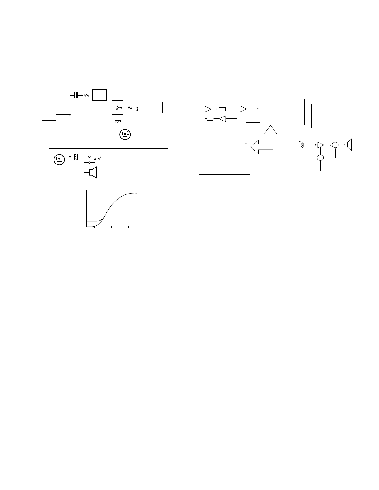
5) Audio Amplifier Circuit
The demodulated signal from IC401 is amplified by IC602,
and goes to AF amplifier through IC601.
The signal then goes through an AF volume control (VR801),
and is routed to an audio power amplifier (IC605) where it is
amplified and output to the speaker.
5R
CIRCUIT DESCRIPTION
RECEIVE SIGNALING
TK-3168
6) Tone Volume Fixed Circuit
This function generates a TONE signal sound even if the
AF volume of the transceiver is the minimum.
A TONE signal is sent through Q602 to the AF amplifier
when, in the FPU, “TONE Volume Fixed” is set to ON.
IC805
CPU
BEEP
BEEPSW
IC601
AQUA
TONE VOL FIXED
+
SP
[VOL Position vs Output Level]
500
ON
25
Output Level (mV)
Min
VOL
Q602
SP-J
OFF
Center Max
IC605
TA7368F
Hi: ON
LOW: OFF
Fig. 4 Tone volume fixed circuit
7) Squelch
Part of the AF signal from the IC enters the FM IC (IC401)
again, and the noise component is amplified and rectified
by a filter and an amplifier to produce a DC voltage
corresponding to the noise level.
The DC signal from the FM IC goes to the analog port of
the microprocessor (IC805). IC805 determines whether to
output sounds from the speaker by checking whether the
input voltage is higher or lower than the preset value.
To output sounds from the speaker, IC805 sends a high
signal to the SP MUTE line and turns IC605 on through
Q603,Q604,Q607 and Q608. (See Fig. 5)
8) Receive Signalling
(1) QT/DQT
The output signal from IF IC (IC401) enters the
microprocessor (IC805) through IC601. IC805 determines
whether the QT or DQT matches the preset value, and
controls the SP MUTE and the speaker output sounds
according to the squelch results.
(2) DTMF
The DTMF input signal from the IF IC (IC401) is amplified
by IC602 and goes to IC601, the DTMF decoder. The
decoded information is then processed by the CPU.
RECEIVE SIGNALING
FM IF IC401
IF Amp
AN SQL
CPU
IC805
IC602
IF Amp
LSDI
HSDI
SP MUTE
SIGNAL
DTMF
QT/DQT
CLK,DATA,
STD,LOADN
IC601
AQUA
IC605
AF PA
Fig. 5 AF amplifier and squelch
3. PLL Frequency Synthesizer
The PLL circuit generates the first local oscillator signal for
reception and the RF signal for transmission.
1) PLL
The frequency step of the PLL circuit is 5 or 6.25kHz.
A 16.8MHz reference an oscillator signal is divided at IC1
by a fixed counter to produce oscillator (VCO) output signal
which is buffer amplified by Q9 then divided in IC1 by a
dual-module programmable counter. The divided signal is
compared in phase with the 5 or 6.25kHz reference signal
from the phase comparator in IC1. The output signal from
the phase comparator is filtered through a low-pass filter
and passed to the VCO to control the oscillator
frequency.(See Fig. 6)
2) VCO
The operating frequency is generated by Q6 in transmit
mode and Q5 in receive mode. The oscillator frequency is
controlled by applying the VCO control voltage, obtained
from the phase comparator, to the varactor diodes (D4 and
D7 in transmit mode and D3 and D9 in receive mode). The
RX pin is set high in receive mode causing Q8 and Q12 to
turn Q6 off and turn Q5 on.
The TX pin is set high in transmit mode. The outputs from
Q5 and Q6 are amplified by Q9 and sent to the RF amplifiers.
Q608
SW
Q603,604,607
SW
SP
7

TK-3168
T
LPF
LPF
D4,7
CIRCUIT DESCRIPTION
Q6
TX VCO
Q9
BUFF AMP
Q7
RF AMP
Q11
RF AMP
MIC
AGC
IC601
AQUA
VCO
Q5
RX VCO
5kHz/6.25kHz
PHASE
COMPARATOR
5kHz/6.25kHz
Q8, 12
T/R SW
CHARGE
PUMP
PLL DATA
X1
16.8MHz
D3,9
PLL IC IC1
1/N
REF OSC
1/M
Fig. 6 PLL circuit
3) Unlock Detector
If a pulse signal appears at the LD pin of IC1, an unlock
condition occurs, and the DC voltage obtained from C19,
R6, and Q1 causes the voltage applied to the microprocessor
to go high. When the microprocessor detects this condition,
the transmitter is disabled, ignoring the push-to-talk switch
input signal.(See Fig. 7)
IC1
PLL IC
R16
LD
C19
5C
R6
Q1
R7
IC805
UL
CPU
Fig. 7 Unlock detector circuit
4. Transmitter System
1) Microphone Amplifier
The signal from the microphone passes through IC601.
When encoding DTMF, it is turned OFF for muting the
microphone input signal by IC601.
The signal passes through the Audio processor (IC601) for
the maximum deviation adjustment, and goes to the VCXO
modulation input.
LPF
IC805
RX
TX
DTMF
CPU
LSDVCO
LSDTCXO
LPF
LPF
X1
TCXO
Fig. 8 Microphone amplifier
2) Drive and Final Amplifier
The signal from the T/R switch (D201 is on) is amplified by
the pre-drive (Q206) and drive amplifier (Q207) to 50mW.
The output of the drive amplifier is amplified by the RF power
amplifier (Q211) to 4.0W (1W when the power is low). The
RF power amplifier consists of two MOS FET stages. The
output of the RF power amplifier is then passed through
the harmonic filter (LPF) and antenna switch (D204 and
D206) and applied to the antenna terminal.
AN
LPF
From
T/R SW
(D201)
Q205
RF
AMP
PCTV
(IC805)
Q206
Pre-DRIVE
AMP
+B
VG
R256
R257
R261
Q207 Q211
DRIVE
AMP
IC201
(1/2)
POWER AMP
VDD
RF
IC201
(2/2)
D204
D206
ANT
SW
VGVG
Fig. 9 Drive and final amplifier and APC circuit
3) APC Circuit
The APC circuit always monitors the current flowing through
the RF power amplifier (Q211) and keeps a constant current.
The voltage drop at R256, R257 and R261 is caused by the
current flowing through the RF power amplifier and this
voltage is applied to the differential amplifier IC201(1/2).
IC201(2/2) compares the output voltage of IC201(1/2) with
the reference voltage from IC805. The output of IC201(2/2)
controls the VG of the RF power amplifier, Drive amplifier
and Pre-Drive amplifier to make both voltages the same.
The change of power high/low is carried out by the change
of the reference voltage.
4) Encode Signalling
(1) QT/DQT
QT,DQT data of the LSDTCXO Line is output from pin 22 of
the CPU. The signal passes through a low-pass CR filter
and goes to the TCXO(X1).
The QT,DQT data of the LSDVCO Line is output from pin
8

CIRCUIT DESCRIPTION
20 of the CPU. The signal passes through a low pass CR
filter, mixes with the audio signal, and goes to the VCO
modulation input. TX deviation is adjusted by the CPU.
(2) DTMF
High-speed data is output from pin 2 of the CPU. The signal
passes through a low-pass CR filter, and provides a TX and
SP out tone, and is then applied to the audio processor
(IC601). The signal is mixed with the audio signal and goes
to the VCO.
TX deviation is adjusted by the CPU.
5. Power Supply
There are 3.5V power supply for PLL circuit and five 5V
power supplies for the microprocessor: 5M,5MS,5C,5R, and
5T. 5M for microprocessor is always output while the power
is on. 5M is always output, but turns off when the power is
turned off to prevent malfunction of the microprocessor.
5C is a common 5V and is output when SAVE is not set to
OFF.
5R is 5V for reception and output during reception.
5T is 5V for transmission and output during transmission.
6. Control Circuit
The control circuit consists of a microprocessor (IC805) and
its peripheral circuits. It controls the TX-RX unit. IC805 mainly
performs the following:
(1) Switching between transmission and reception by the
PTT signal input.
(2) Reading system, group, frequency, and program data
from the memory circuit.
(3) Sending frequency program data to the PLL.
(4) Controlling squelch on/off by the DC voltage from the
squelch circuit.
(5) Controlling the audio mute circuit by the decode data
input.
(6) Transmitting tone and encode data.
1) Frequency Shift Circuit
The microprocessor (IC805) operates at a clock of
7.3728MHz. This oscillator has a circuit that shifts the
frequency by BEAT SHIFT SW (Q810).
A beat sound may be able to be evaded from generation if
“Beat Shift” is set to ON when it is generated in the internal
spurious transmission modulated sound of a transceiver.
TK-3168
X801C834
Q810
Hi: OFF
LOW: ON
Fig. 10 Frequency shift circuit
2) Memory Circuit
Memory circuit consists of the CPU (IC805) and an EEPROM
(IC804). An EEPROM has a capacity of 64k bits that contains
the transceiver control program for the CPU and data such
as transceiver channels and operating features.
IC805
CPU
Fig. 11 Memory circuit
3) Low Battery Warning
The battery voltage is checked using by the microprocessor.
The transceiver generates a warning tone when it falls below
the warning voltage shown in the table.
(1)The red LED blinks when the battery voltage falls below
the voltage (1) shown in the table during transmission.
(2)The red LED blinks when the battery voltage falls below
the voltage (2) shown in the table during transmission.
Note:
The transceiver checks the battery voltage during reception
even when, in the FPU, the Battery Warning status function
is set to “On TX” (default setting).
However, the LED does not blink during reception. During
transmission, the LED blinks to generate the warning tone
of a low battery voltage.
(3)The transceiver immediately stops transmission when
the battery voltage falls below the voltage (3) shown in
the table. A message tone beeps while the PTT switch
is released.
Battery Case Li-ion Battery Ni-Cd Battery Ni-MH Battery
(1) 6.2[V] 6.5[V] 6.2[V] 6.2[V]
(2) 7.5[V] 7.1[V] 6.8[V] 7.0[V]
(3) 5.9[V] 6.2[V] 5.9[V] 5.9[V]
XOUT
IC805
BSHIFT
IC804
EEPROM
SB
R833
R834
Fig. 12 Low battery warning
IC805
88
CPU
9
TK-3168
R608
C608
C619
C1
C3
CIRCUIT DESCRIPTION / INSTALLATION
4) Battery Type Detection
The transceiver automatically detects teh battery type,
measuring the resistance between the S-terminal and +
terminal on the battery pack and changes the supplied
voltage to the S-tarminal as below. The microprocessor then
detects the battery type.
Resistor value Battery type Input voltage of S-terminal
1.8MΩ Li-ion 0.3~1.3V
560kΩ Ni-Cd 1.3~2.6V
220kΩ Ni-MH 2.6~5.0V
OPEN Battery case 0~0.3V
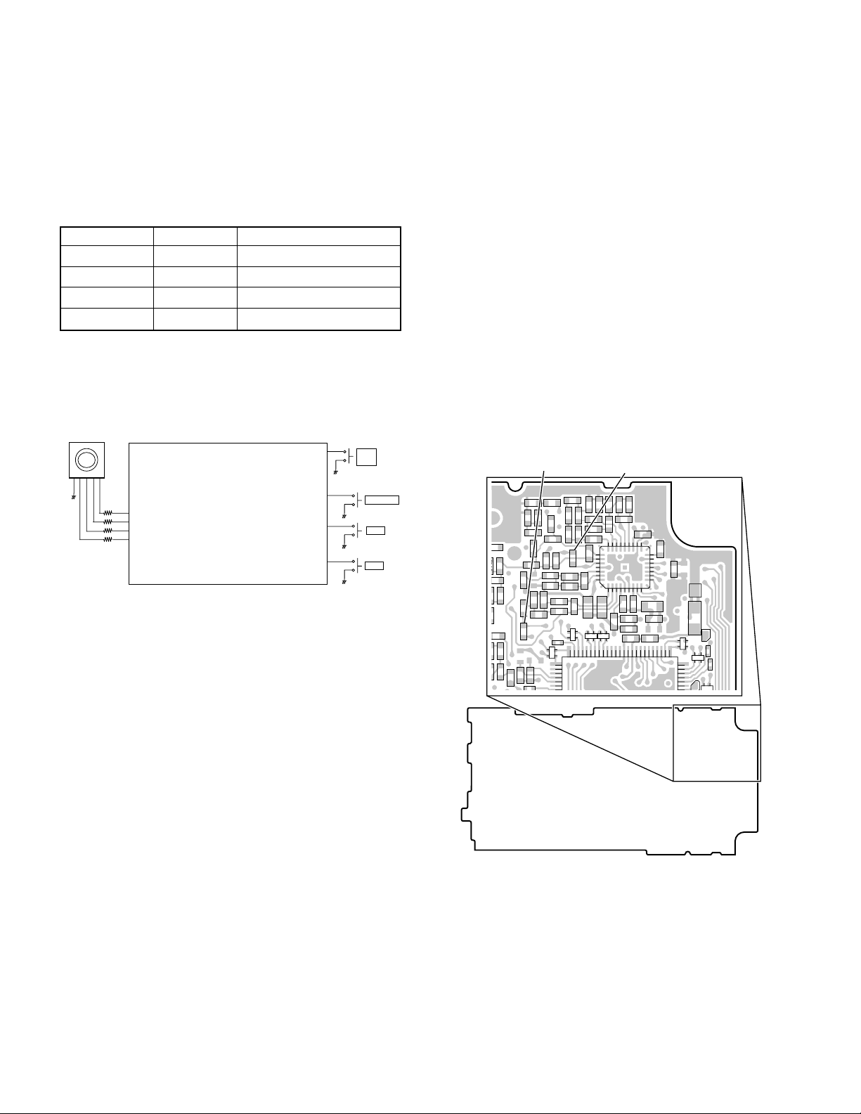
7. Control System
Keys and channel selector circuit.
The signal from keys and channel selector input to
microprocessor directly as shown in fig. 13.
Channel selector
70
EN1
69
EN2
68
EN3
67
EN4
IC805
CPU
Fig. 13 Control system
PTT
AUXSW
SIDE 1
SIDE 2
34
PTT
SW
74
AUX SW
75
SW1
76
SW2
INSTALLATION
1. Optional Board
Remove the TX/RX unit from the radio before installing the
optional board in the radio.
The procedure for removing the TX/RX unit is described in
the DISASSEMBLY FOR REPAIR section in the Service
Manual.
Install the optional board on the back of the TX/RX unit.
For details on installation of the optional board, refer to
Installation Information supplied with the optional board.
When installing the optional board, also refer to the chart in
TERMINAL FUNCTION section (page 11) given in the Service
Manual.
Note: To install and use the Scrambler Board, remove “R601”
and “R647” from the front of the TX/RX unit.
R647 R601
R633
C607
R607
R609
C609
C614
617
C618
616
R610
R1
R2
R3
R640
R613
R615
R696
R643
C648
C646
C637
R636
C641
R634
R647
CP803
C4
R839
R840
C645
R629
R631
R835
R628
R642
R641
76
C642
R632
CP808
75
R627
C634
R601
C633
C636
C627
C628
R626
R623
C631
C632
26
C640
32
19
C643
++
C621
C622
CP809
CP810
C625
IC601
C630
R622
R624
R625
R621
C846
R618
C635
R695
1725
R616
16
L806
10
+
C610
C613
L804
C847
+
VCC
CP812
51
R855
50
CP813
R856
CE
TX-RX UNIT (X57-6730-XX)
Component side view
10

TK-3168
TERMINAL FUNCTION
■ CN801
Pin
Designation
No.
1 GND GND Vss
2 SB Switched B Output Voltage/7mA load DC (Battery terminal) ±0.5V
3 A3 AUX3 Load >100kΩ (Low) Vss ~ 0.4V (High) Vdd-0.8V ~ Vdd
4 TXAFI Transmit AF input Input sensitivity/Impedance (1kHz std. dev.) 280±50mVrms @22kΩ Load
5 A2 AUX2 Load >100kΩ (Low) Vss ~ 0.4V (High) Vdd-0.8V ~ Vdd
6 A6 AUX6 Load >100kΩ (Low) Vss ~ 0.4V (High) Vdd-0.8V ~ Vdd
7 A1 AUX1 Load >100kΩ (Low) Vss ~ 0.4V (High) Vdd-0.8V ~ Vdd
8 A5 AUX5 Load >100kΩ (Low) Vss ~ 0.4V (High) Vdd-0.8V ~ Vdd
9 A4 AUX4 Load >100kΩ (Low) Vss ~ 0.4V (High) Vdd-0.8V ~ Vdd
10 NC Non connection Non connection
11 5C DC 5V Output Voltage/10mA load 5.0±0.5V
12 DEO Discriminator signal output Output voltage/Impedance (1kHz std. mod.) 280±50mVrms @2.2kΩ Load
13 TXAFI Transmit AF input Input sensitivity/Impedance (1kHz std. dev.) 280±50mVrms @22kΩ Load
14 DEO Discriminator signal output Output voltage/Impedance (1kHz std. mod.) 280±50mVrms @2.2kΩ Load
15 NC Non connection Non connection
16 ALT Sidetone input
17 NC Non connection Non connection
18 NC Non connection Non connection
19 NC Non connection Non connection
20 GND GND Vss
Function Condition Value
Input sensitivity/Impedance
(1kHz rated AF power/Vol. MAX)
7 ±3mVrms @22kΩ Load
■ Solder point connection
Designation
MIC_I Mic input Input sensitivity/Impedance (1kHz std. dev.) 7±3mVrms @22kΩ Load
MIC_O Mic o utput
RA_I Receiver AF input Input sensitivity/Impedance (1kHz rated AF power/Vol. MAX) 75±20mVrms @22kΩ Load
RA_O Receiver AF output
A1 AUX1 Load >100kΩ (Low) Vss ~ 0.4V (High) Vdd-0.8V ~ Vdd
A2 AUX2 Load >100kΩ (Low) Vss ~ 0.4V (High) Vdd-0.8V ~ Vdd
A3 AUX3 Load >100kΩ (Low) Vss ~ 0.4V (High) Vdd-0.8V ~ Vdd
A4 AUX4 Load >100kΩ (Low) Vss ~ 0.4V (High) Vdd-0.8V ~ Vdd
A5 AUX5 Load >100kΩ (Low) Vss ~ 0.4V (High) Vdd-0.8V ~ Vdd
A6 AUX6 Load >100kΩ (Low) Vss ~ 0.4V (High) Vdd-0.8V ~ Vdd
SB Switched B Output Voltage/7mA load DC (Battery terminal) ±0.5V
GND GND Vss
5C DC 5V Output Voltage/10mA load 5.0±0.5V
TXAFI Transmit AF input Input sensitivity/Impedance (1kHz std. dev.) 280±50mVrms @22kΩ Load
DEO Discriminator signal output Output voltage/Impedance (1kHz std. mod.) 280±50mVrms @2.2kΩ Load
LSDFO Received sub-tone output Output voltage/Impedance (150Hz 15% mod.) 180±50mVrms @2.2kΩ Load
ALT Sidetone input Input sensitivity/Impedance (1kHz rated AF power/Vol. MAX) 7±3mVrms @22kΩ Load
Function Condition Value
Output voltage/Impedance (1kHz 15mVrms mic input) 2.6±1.0mVrms @2.2kΩ Load
Output voltage/Impedance (1kHz 100mVrms mic input) 90±20mVrms @100kΩ Load
Output voltage/Impedance (1kHz std. mod.) 150±50mVrms @2.2kΩ Load
Output voltage/Impedance (1kHz system mod.) 290±50mVrms @100kΩ Load
11

TK-3168
SEMICONDUCTOR DATA
Microprocessor : M30622MCA7G7GP (TX-RX UNIT : IC805)
■ Pin function
Pin Port
No. Name
1 PCTV O APC/BPF control data output.
2 DTMF O DTMF
3NC - NC
4 EEPDAT I/O EEPROM data input/output.
5 EEPCLK O EEPROM Clock
6 BYTE I GND.
7 CNVSS I GND.
8 AUX5 O Option Board 5
9 AUX6 O Option Board 6
10 RESET I CPU reset.
11 XOUT O CPU clock.
12 VSS - GND.
13 XIN I CPU clock.
14 VCC - +5V.
15 NC I NC
16 INT I Battery voltage monitor input Low battery : L
17 RDF/FD I Base Band IC Data input
TCLK/
18
DTRDI
19 NC - NC
20 LSDVCO O Low speed data output. (VCO)
21 NC I NC
22
LSDTCXO
23 NC I NC
24 BEEP O Beep output.
25 OPTDET I Option detect input
26 NC - NC
27 NC - NC
28 NC - NC
29 AUX4 O Option board port 4
30 AUX2 I/O Option board port 2
31 NC - NC
32 NC - NC
33 TXD I/O Serial data.
34 PTT/RXD I PTT on : L/Serial data.
35 STD I Base Band IC Data input
36 BBDIR O Base Band IC Data output
37 BBCLK O Base Band IC clock output
38 BBDI/O I/O Base Band IC Data input/output
39 NC - NC
TDATA/
40
DTRCLK
41
DTRLOADN
42 AUX3 O Option board port 3
43 AUX1 O Option board port 1
44 NC - NC
45 NC - NC
46 DSW O APC voltage discharge Switch
47
BEEPSW
48 AFCOUT O AF amp power supply control
49 AFMUTE O RX audio mute
50 NC - NC
51 TX O TX VCO power supply switch TX:L
52 RX O RX VCO power supply switch RX:L
I/O Function
I Base Band IC Data input
O Low speed data output. (TCXO)
O Base Band IC Data output
O Base Band IC Data output
O Beep switch.
12
Pin Port
No. Name
53 BSHIFT O Beet shift switch.
54 W/N O W/N switch Wide:L
55 NC - NC
56 APCSW O APC switch output.
57 SAVE O Battery save output.
58 5TC O 5T control output.
59 5RC O 5R control output.
60 VCC - +5V.
61 5MSC O 5M control output.
62 VSS - GND.
63 NC - NC
64 NC - NC
65 NC - NC
66 NC - NC
67 EN4 I CH selector input 4.
68 EN3 I CH selector input 3.
69 EN2 I CH selector input 2.
70 EN1 I CH selector input 1.
71 NC - NC
72 LEDTX O RED LED lights control output
73 LEDRX O GREEN LED lights control output
74 AUXSW I Key input.(Emergency)
75 SIDE1 I Side key 1 input.
76 SIDE2 I Side key 2 input.
77 NC - NC
78 NC - NC
79 SIM1 I Destination select 1.
80 SIM2 I Destination select 2.
81 NC - NC
82 PLLUL I PLL unlock detect input. unlock : L
83 RFCLK O PLL clock output. Latch : L
84 RFDAT O PLL data output.
85 PS O PLL power save output.
86 PLLSTB O PLL strobe output.
87
88 BATT I Battery voltage input.
89 VOX I VOX input.
90 RSSQL I Received signal strength indicator input.
91 ANSQL I Squelch level input.
92 LSDI I Low speed data input (QT/DQT).
93 THM I Thermistor input.
94 AVSS - GND.
95 NC - NC
96 VREF - +5V.
97 AVCC - +5V.
98 NC - NC
99 NC - NC
100 NC - NC
BATTSEL
I/O Function
I Battery distinction input.

COMPONENTS DESCRIPTION
TX-RX UNIT (X57-673X-XX)
Ref. No.
IC201 IC Comparator (APC)
IC401 IC FM IF system
IC601 IC Audio processor
IC602 IC AF AMP
IC604 IC VOX AMP
IC605 IC AF power AMP
IC801 IC Voltage regulator / 5V
IC802 IC Voltage detector / Reset
IC803 IC Voltage detector / INT
IC804 IC EEPROM
IC805 IC Microprocessor
IC806 IC Flip Flop
Q10 Transistor Ripple filter
Q11 Transistor RF AMP
Q12 FET DC switch / RX VCO
Q205 Transistor Pre-drive AMP
Q206 FET Pre-drive AMP
Q207 FET TX Drive AMP
Q208 Transistor APC switch
Q209 FET APC switch
Q210 Transistor APC switch
Q211 FET TX Final AMP
Q212 FET APC switch
Q213 Transistor APC switch
Q401 Transistor W/N switch
Q402 Transistor IF AMP
Q403 FET Mixer
Q404 FET RF AMP
Q407 FET DC switch
Q601 FET AF Mute
Q602 FET Beep switch
Q603 Transistor DC switch / SP Mute
Q604 Transistor DC switch
Q605 Transistor MIC AGC
Q606 Transistor MIC AGC
Q607 Transistor DC switch / SP Mute
Q608 FET SP Mute switch
Q801 Transistor 5T switch
Q802(1/2) FET 5TC switch
Q802(2/2) FET SAVE switch
Q803(1/2) Transistor AVR / 5C
Q803(2/2) Transistor AVR / 5T
Q804 Transistor 5C switch
Use/Function
IC1 IC PLL system
Q1 Transistor Level shift
Q2 Transistor Level shift
Q3 Transistor Level shift
Q4 Transistor Tripler
Q5 FET VCO / RX
Q6 FET VCO / TX
Q7 Transistor PLL IC f_in AMP
Q8 FET DC switch / TX VCO
Q9 Transistor RF Buffer AMP
Operation/Condition
TK-3168
Ref. No.
Q805(1/2) Transistor LED switch / Green
Q805(2/2) Transistor LED switch / Red
Q806 Transistor AVR / PLLB
Q807 Transistor PLLB switch
Q808 Transistor 5MS switch
Q809 Transistor 5R switch
Q810 FET Beet shift switch
D201 Diode TX/RX RF switch
D203 Zener diode APC protect
D204 Diode ANT switch
D206 Diode ANT switch
D208 Diode ANT switch
D212 Diode ANT switch
D401 Diode TX/RX RF switch
D402
D403
D404
D405
D406
D407 Diode Rectifier
D603 Diode Limitter
D604 Diode Detector
D605 Diode Detector
D606 Diode Detector
D801 Diode 5M protect
D802 LED LED / Red
D803 LED LED / Green
D805 Diode Reverse protection
Use/Function
Variable
D3
capacitance diode
Variable
D4
capacitance diode
Variable
D7
capacitance diode
Variable
D9
capacitance diode
Variable
D10
capacitance diode
D11 Diode Current steering
Variable
capacitance diode
Variable
capacitance diode
Variable
capacitance diode
Variable
capacitance diode
Variable
capacitance diode
Frequency control / RX VCO
Frequency control / TX VCO
Frequency control / TX VCO
Frequency control / RX VCO
Modulation
RF BPF tuning
RF BPF tuning
RF BPF tuning
RF BPF tuning
RF BPF tuning
Operation/Condition
13
 Loading...