

Page 1
UHF FM TRANSCEIVER
TK-3160
SERVICE MANUAL
SUPPLEMENT
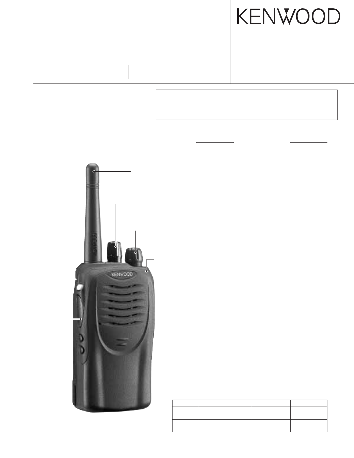
Knob (CH-SELECTOR)
(K29-9280-13)
E3 version
This TK-3160 service manual contains a number of sections which
differ from the service manual (B51-8674-00) for the TK-3160.
For items other than those in this TK-3160 service manual please
refer to the service manual (B51-8674-00) for the TK-3160.
Antenna
(KRA-23: Option)
Knob (VOLUME)
(K29-9278-13)
© 2004-3 PRINTED IN JAPAN
B51-8681-00 (S) 726
CONTENTS
GENERAL .............................................................2
SYSTEM SET-UP .................................................2
INSTALLATION....................................................3
TERMINAL FUNCTION........................................4
PARTS LIST..........................................................5
EXPLODED VIEW...............................................13
PACKING ............................................................ 14
ADJUSTMENT ................................................... 15
PC BOARD
TX-RX UNIT (X57-6732-72)..........................20
SCHEMATIC DIAGRAM.....................................24
SPECIFICATIONS............................BACK COVER
Knob (PTT)
(K29-9332-03)
Cabinet assy
(A02-3826-43)
Does not come with antenna.
Antenna is available as an option.
Service Manual List
Title Parts number Remarks Destination
TK-3160 B51-8674-00 E, X2
TK-3160
B51-8681-00
(This service manual)
SUPPLEMENT E3
Page 2
TK-3160
GENERAL / SYSTEM SET-UP
INTRODUCTION
SCOPE OF THIS MANUAL
This manual is intended for use by experienced technicians
familiar with similar types of commercial grade
communications equipment. It contains all required service
information for the equipment and is current as of the
publication date. Changes which may occur after publication
are covered by either Service Bulletins or Manual Revisions.
These are issued as required.
ORDERING REPLACEMENT PARTS
When ordering replacement parts or equipment information,
the full part identification number should be included. This
applies to all parts, components, kits, or chassis. If the part
number is not known, include the chassis or kit number of
which it is a part, and a sufficient description of the required
component for proper identification.
Unit
Model
& destination
TK-3160
TX-RX Unit Frequency range Remarks
E3 X57-6732-72 400~430MHz
IF1 : 49.95MHz
LOC : 50.4MHz
PERSONAL SAFETY
The following precautions are recommended for personal
safety:
●
DO NOT transmit until all RF connectors are verified secure
and any open connectors are properly terminated.
●
SHUT OFF and DO NOT operate this equipment near
electrical blasting caps or in an explosive atmosphere.
●
This equipment should be serviced by a qualified technician only.
SERVICE
This radio is designed for easy servicing. Refer to the
schematic diagrams, printed circuit board views, and alignment
procedures contained within.
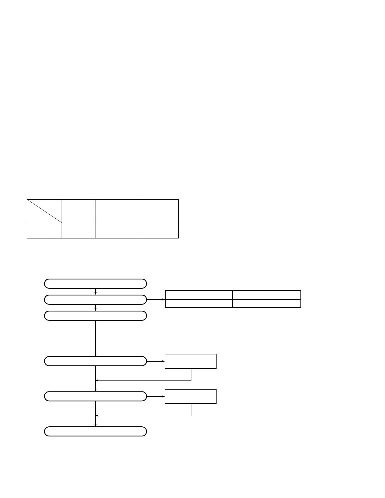
SYSTEM SET-UP
Merchandise received
Choose the type of transceiver
Transceiver programming
Are you using the optional antenna?
Are you using the speaker microphone?
NO
NO
Delivery
Frequency range (MHz) RF power Type
TX/RX 400~430
A personal computer (IBM PC or compatible), programming
interface (KPG-22), and programming software (KPG-82D)
are required for programming.
(The frequency, TX power HI/LOW, and signalling data are programmed
for the transceiver.)
YES
YES
KRA-23 or KRA-27
Optional antenna
KMC-17 or KMC-21
Speaker microphone
(Option)
4.0W
TK-3160 (E3)
2
Page 3

INSTALLATION
R608
C608
C619
C1
C3
INSTALLATION
1. Optional Board
Remove the TX/RX unit from the radio before installing the
optional board in the radio.
The procedure for removing the TX/RX unit is described in
the DISASSEMBLY FOR REPAIR section in the Service
Manual.
Install the optional board on the back of the TX/RX unit.
For details on installation of the optional board, refer to
Installation Information supplied with the optional board.
When installing the optional board, also refer to the chart in
TERMINAL FUNCTION section (page 4) given in the Service
Manual.
Note: To install and use the Scrambler Board, remove “R601”
and “R647” from the front of the TX/RX unit.
TK-3160
R647 R601
R633
C607
R607
C609
R609
C614
617
C618
616
R610
R1
R2
R3
R640
R613
R615
R696
R643
C648
C646
R636
C637
C641
R634
R647
CP803
C4
R839
R840
TX-RX UNIT (X57-6732-72)
Component side view
C645
R629
R631
R835
R628
R642
R641
76
C642
R632
CP808
75
R627
C634
R601
C633
C636
C628
R626
C631
C632
26
C640
32
19
C643
++
C621
C622
CP809
CP810
C627
R623
C625
IC601
C630
R622
R624
R625
R621
C846
R618
C635
R695
1725
R616
16
L806
10
+
C610
C613
L804
C847
+
VCC
CP812
51
R855
50
CP813
R856
CE
3
Page 4

TK-3160
TERMINAL FUNCTION
■ Solder point connection
Designation
MIC_I Mic input Input sensitivity/Impedance (1kHz std. dev.) 7±3mVrms @22kΩ Load
MIC_O Mic o utput
RA_I Receiver AF input Input sensitivity/Impedance (1kHz rated AF power/Vol. MAX) 75±20mVrms @22kΩ Load
RA_O Receiver AF output
A1 AUX1 Load >100kΩ (Low) Vss ~ 0.4V (High) Vdd-0.8V ~ Vdd
A2 AUX2 Load >100kΩ (Low) Vss ~ 0.4V (High) Vdd-0.8V ~ Vdd
A3 AUX3 Load >100kΩ (Low) Vss ~ 0.4V (High) Vdd-0.8V ~ Vdd
A4 AUX4 Load >100kΩ (Low) Vss ~ 0.4V (High) Vdd-0.8V ~ Vdd
A5 AUX5 Load >100kΩ (Low) Vss ~ 0.4V (High) Vdd-0.8V ~ Vdd
A6 AUX6 Load >100kΩ (Low) Vss ~ 0.4V (High) Vdd-0.8V ~ Vdd
SB Switched B Output Voltage/7mA load DC (Battery terminal) ±0.5V
GND GND Vss
5C DC 5V Output Voltage/10mA load 5.0±0.5V
TXAFI Transmit AF input Input sensitivity/Impedance (1kHz std. dev.) 280±50mVrms @22kΩ Load
DEO Discriminator signal output Output voltage/Impedance (1kHz std. mod.) 280±50mVrms @2.2kΩ Load
LSDFO Received sub-tone output Output voltage/Impedance (150Hz 15% mod.) 180±50mVrms @2.2kΩ Load
ALT Sidetone input Input sensitivity/Impedance (1kHz rated AF power/Vol. MAX) 7±3mVrms @22kΩ Load
Function Condition Value
Output voltage/Impedance (1kHz 15mVrms mic input) 2.6±1.0mVrms @2.2kΩ Load
Output voltage/Impedance (1kHz 100mVrms mic input) 90±20mVrms @100kΩ Load
Output voltage/Impedance (1kHz std. mod.) 150±50mVrms @2.2kΩ Load
Output voltage/Impedance (1kHz system mod.) 290±50mVrms @100kΩ Load
4
 Loading...